JP2020528126A - Fiber reinforced pressure vessel - Google Patents
Fiber reinforced pressure vessel Download PDFInfo
- Publication number
- JP2020528126A JP2020528126A JP2020504220A JP2020504220A JP2020528126A JP 2020528126 A JP2020528126 A JP 2020528126A JP 2020504220 A JP2020504220 A JP 2020504220A JP 2020504220 A JP2020504220 A JP 2020504220A JP 2020528126 A JP2020528126 A JP 2020528126A
- Authority
- JP
- Japan
- Prior art keywords
- fiber
- twisted
- pressure vessel
- central portion
- fibers
- Prior art date
- Legal status (The legal status is an assumption and is not a legal conclusion. Google has not performed a legal analysis and makes no representation as to the accuracy of the status listed.)
- Granted
Links
Images
Classifications
-
- F—MECHANICAL ENGINEERING; LIGHTING; HEATING; WEAPONS; BLASTING
- F17—STORING OR DISTRIBUTING GASES OR LIQUIDS
- F17C—VESSELS FOR CONTAINING OR STORING COMPRESSED, LIQUEFIED OR SOLIDIFIED GASES; FIXED-CAPACITY GAS-HOLDERS; FILLING VESSELS WITH, OR DISCHARGING FROM VESSELS, COMPRESSED, LIQUEFIED, OR SOLIDIFIED GASES
- F17C1/00—Pressure vessels, e.g. gas cylinder, gas tank, replaceable cartridge
- F17C1/02—Pressure vessels, e.g. gas cylinder, gas tank, replaceable cartridge involving reinforcing arrangements
- F17C1/04—Protecting sheathings
- F17C1/06—Protecting sheathings built-up from wound-on bands or filamentary material, e.g. wires
-
- F—MECHANICAL ENGINEERING; LIGHTING; HEATING; WEAPONS; BLASTING
- F17—STORING OR DISTRIBUTING GASES OR LIQUIDS
- F17C—VESSELS FOR CONTAINING OR STORING COMPRESSED, LIQUEFIED OR SOLIDIFIED GASES; FIXED-CAPACITY GAS-HOLDERS; FILLING VESSELS WITH, OR DISCHARGING FROM VESSELS, COMPRESSED, LIQUEFIED, OR SOLIDIFIED GASES
- F17C13/00—Details of vessels or of the filling or discharging of vessels
- F17C13/002—Details of vessels or of the filling or discharging of vessels for vessels under pressure
-
- F—MECHANICAL ENGINEERING; LIGHTING; HEATING; WEAPONS; BLASTING
- F17—STORING OR DISTRIBUTING GASES OR LIQUIDS
- F17C—VESSELS FOR CONTAINING OR STORING COMPRESSED, LIQUEFIED OR SOLIDIFIED GASES; FIXED-CAPACITY GAS-HOLDERS; FILLING VESSELS WITH, OR DISCHARGING FROM VESSELS, COMPRESSED, LIQUEFIED, OR SOLIDIFIED GASES
- F17C13/00—Details of vessels or of the filling or discharging of vessels
-
- F—MECHANICAL ENGINEERING; LIGHTING; HEATING; WEAPONS; BLASTING
- F17—STORING OR DISTRIBUTING GASES OR LIQUIDS
- F17C—VESSELS FOR CONTAINING OR STORING COMPRESSED, LIQUEFIED OR SOLIDIFIED GASES; FIXED-CAPACITY GAS-HOLDERS; FILLING VESSELS WITH, OR DISCHARGING FROM VESSELS, COMPRESSED, LIQUEFIED, OR SOLIDIFIED GASES
- F17C2201/00—Vessel construction, in particular geometry, arrangement or size
- F17C2201/01—Shape
- F17C2201/0104—Shape cylindrical
- F17C2201/0109—Shape cylindrical with exteriorly curved end-piece
-
- F—MECHANICAL ENGINEERING; LIGHTING; HEATING; WEAPONS; BLASTING
- F17—STORING OR DISTRIBUTING GASES OR LIQUIDS
- F17C—VESSELS FOR CONTAINING OR STORING COMPRESSED, LIQUEFIED OR SOLIDIFIED GASES; FIXED-CAPACITY GAS-HOLDERS; FILLING VESSELS WITH, OR DISCHARGING FROM VESSELS, COMPRESSED, LIQUEFIED, OR SOLIDIFIED GASES
- F17C2203/00—Vessel construction, in particular walls or details thereof
- F17C2203/06—Materials for walls or layers thereof; Properties or structures of walls or their materials
- F17C2203/0602—Wall structures; Special features thereof
- F17C2203/0604—Liners
-
- F—MECHANICAL ENGINEERING; LIGHTING; HEATING; WEAPONS; BLASTING
- F17—STORING OR DISTRIBUTING GASES OR LIQUIDS
- F17C—VESSELS FOR CONTAINING OR STORING COMPRESSED, LIQUEFIED OR SOLIDIFIED GASES; FIXED-CAPACITY GAS-HOLDERS; FILLING VESSELS WITH, OR DISCHARGING FROM VESSELS, COMPRESSED, LIQUEFIED, OR SOLIDIFIED GASES
- F17C2203/00—Vessel construction, in particular walls or details thereof
- F17C2203/06—Materials for walls or layers thereof; Properties or structures of walls or their materials
- F17C2203/0634—Materials for walls or layers thereof
- F17C2203/0658—Synthetics
- F17C2203/0663—Synthetics in form of fibers or filaments
- F17C2203/0665—Synthetics in form of fibers or filaments radially wound
-
- F—MECHANICAL ENGINEERING; LIGHTING; HEATING; WEAPONS; BLASTING
- F17—STORING OR DISTRIBUTING GASES OR LIQUIDS
- F17C—VESSELS FOR CONTAINING OR STORING COMPRESSED, LIQUEFIED OR SOLIDIFIED GASES; FIXED-CAPACITY GAS-HOLDERS; FILLING VESSELS WITH, OR DISCHARGING FROM VESSELS, COMPRESSED, LIQUEFIED, OR SOLIDIFIED GASES
- F17C2203/00—Vessel construction, in particular walls or details thereof
- F17C2203/06—Materials for walls or layers thereof; Properties or structures of walls or their materials
- F17C2203/0634—Materials for walls or layers thereof
- F17C2203/0658—Synthetics
- F17C2203/0663—Synthetics in form of fibers or filaments
- F17C2203/0668—Synthetics in form of fibers or filaments axially wound
-
- F—MECHANICAL ENGINEERING; LIGHTING; HEATING; WEAPONS; BLASTING
- F17—STORING OR DISTRIBUTING GASES OR LIQUIDS
- F17C—VESSELS FOR CONTAINING OR STORING COMPRESSED, LIQUEFIED OR SOLIDIFIED GASES; FIXED-CAPACITY GAS-HOLDERS; FILLING VESSELS WITH, OR DISCHARGING FROM VESSELS, COMPRESSED, LIQUEFIED, OR SOLIDIFIED GASES
- F17C2203/00—Vessel construction, in particular walls or details thereof
- F17C2203/06—Materials for walls or layers thereof; Properties or structures of walls or their materials
- F17C2203/0634—Materials for walls or layers thereof
- F17C2203/0658—Synthetics
- F17C2203/0663—Synthetics in form of fibers or filaments
- F17C2203/067—Synthetics in form of fibers or filaments helically wound
-
- F—MECHANICAL ENGINEERING; LIGHTING; HEATING; WEAPONS; BLASTING
- F17—STORING OR DISTRIBUTING GASES OR LIQUIDS
- F17C—VESSELS FOR CONTAINING OR STORING COMPRESSED, LIQUEFIED OR SOLIDIFIED GASES; FIXED-CAPACITY GAS-HOLDERS; FILLING VESSELS WITH, OR DISCHARGING FROM VESSELS, COMPRESSED, LIQUEFIED, OR SOLIDIFIED GASES
- F17C2203/00—Vessel construction, in particular walls or details thereof
- F17C2203/06—Materials for walls or layers thereof; Properties or structures of walls or their materials
- F17C2203/0634—Materials for walls or layers thereof
- F17C2203/0658—Synthetics
- F17C2203/0663—Synthetics in form of fibers or filaments
- F17C2203/0673—Polymers
-
- F—MECHANICAL ENGINEERING; LIGHTING; HEATING; WEAPONS; BLASTING
- F17—STORING OR DISTRIBUTING GASES OR LIQUIDS
- F17C—VESSELS FOR CONTAINING OR STORING COMPRESSED, LIQUEFIED OR SOLIDIFIED GASES; FIXED-CAPACITY GAS-HOLDERS; FILLING VESSELS WITH, OR DISCHARGING FROM VESSELS, COMPRESSED, LIQUEFIED, OR SOLIDIFIED GASES
- F17C2209/00—Vessel construction, in particular methods of manufacturing
- F17C2209/21—Shaping processes
- F17C2209/2154—Winding
-
- F—MECHANICAL ENGINEERING; LIGHTING; HEATING; WEAPONS; BLASTING
- F17—STORING OR DISTRIBUTING GASES OR LIQUIDS
- F17C—VESSELS FOR CONTAINING OR STORING COMPRESSED, LIQUEFIED OR SOLIDIFIED GASES; FIXED-CAPACITY GAS-HOLDERS; FILLING VESSELS WITH, OR DISCHARGING FROM VESSELS, COMPRESSED, LIQUEFIED, OR SOLIDIFIED GASES
- F17C2209/00—Vessel construction, in particular methods of manufacturing
- F17C2209/23—Manufacturing of particular parts or at special locations
- F17C2209/234—Manufacturing of particular parts or at special locations of closing end pieces, e.g. caps
-
- F—MECHANICAL ENGINEERING; LIGHTING; HEATING; WEAPONS; BLASTING
- F17—STORING OR DISTRIBUTING GASES OR LIQUIDS
- F17C—VESSELS FOR CONTAINING OR STORING COMPRESSED, LIQUEFIED OR SOLIDIFIED GASES; FIXED-CAPACITY GAS-HOLDERS; FILLING VESSELS WITH, OR DISCHARGING FROM VESSELS, COMPRESSED, LIQUEFIED, OR SOLIDIFIED GASES
- F17C2221/00—Handled fluid, in particular type of fluid
- F17C2221/01—Pure fluids
- F17C2221/012—Hydrogen
-
- F—MECHANICAL ENGINEERING; LIGHTING; HEATING; WEAPONS; BLASTING
- F17—STORING OR DISTRIBUTING GASES OR LIQUIDS
- F17C—VESSELS FOR CONTAINING OR STORING COMPRESSED, LIQUEFIED OR SOLIDIFIED GASES; FIXED-CAPACITY GAS-HOLDERS; FILLING VESSELS WITH, OR DISCHARGING FROM VESSELS, COMPRESSED, LIQUEFIED, OR SOLIDIFIED GASES
- F17C2221/00—Handled fluid, in particular type of fluid
- F17C2221/03—Mixtures
- F17C2221/032—Hydrocarbons
- F17C2221/033—Methane, e.g. natural gas, CNG, LNG, GNL, GNC, PLNG
-
- F—MECHANICAL ENGINEERING; LIGHTING; HEATING; WEAPONS; BLASTING
- F17—STORING OR DISTRIBUTING GASES OR LIQUIDS
- F17C—VESSELS FOR CONTAINING OR STORING COMPRESSED, LIQUEFIED OR SOLIDIFIED GASES; FIXED-CAPACITY GAS-HOLDERS; FILLING VESSELS WITH, OR DISCHARGING FROM VESSELS, COMPRESSED, LIQUEFIED, OR SOLIDIFIED GASES
- F17C2223/00—Handled fluid before transfer, i.e. state of fluid when stored in the vessel or before transfer from the vessel
- F17C2223/01—Handled fluid before transfer, i.e. state of fluid when stored in the vessel or before transfer from the vessel characterised by the phase
- F17C2223/0107—Single phase
- F17C2223/0123—Single phase gaseous, e.g. CNG, GNC
-
- F—MECHANICAL ENGINEERING; LIGHTING; HEATING; WEAPONS; BLASTING
- F17—STORING OR DISTRIBUTING GASES OR LIQUIDS
- F17C—VESSELS FOR CONTAINING OR STORING COMPRESSED, LIQUEFIED OR SOLIDIFIED GASES; FIXED-CAPACITY GAS-HOLDERS; FILLING VESSELS WITH, OR DISCHARGING FROM VESSELS, COMPRESSED, LIQUEFIED, OR SOLIDIFIED GASES
- F17C2223/00—Handled fluid before transfer, i.e. state of fluid when stored in the vessel or before transfer from the vessel
- F17C2223/03—Handled fluid before transfer, i.e. state of fluid when stored in the vessel or before transfer from the vessel characterised by the pressure level
- F17C2223/036—Very high pressure (>80 bar)
-
- F—MECHANICAL ENGINEERING; LIGHTING; HEATING; WEAPONS; BLASTING
- F17—STORING OR DISTRIBUTING GASES OR LIQUIDS
- F17C—VESSELS FOR CONTAINING OR STORING COMPRESSED, LIQUEFIED OR SOLIDIFIED GASES; FIXED-CAPACITY GAS-HOLDERS; FILLING VESSELS WITH, OR DISCHARGING FROM VESSELS, COMPRESSED, LIQUEFIED, OR SOLIDIFIED GASES
- F17C2270/00—Applications
- F17C2270/01—Applications for fluid transport or storage
- F17C2270/0165—Applications for fluid transport or storage on the road
- F17C2270/0168—Applications for fluid transport or storage on the road by vehicles
-
- Y—GENERAL TAGGING OF NEW TECHNOLOGICAL DEVELOPMENTS; GENERAL TAGGING OF CROSS-SECTIONAL TECHNOLOGIES SPANNING OVER SEVERAL SECTIONS OF THE IPC; TECHNICAL SUBJECTS COVERED BY FORMER USPC CROSS-REFERENCE ART COLLECTIONS [XRACs] AND DIGESTS
- Y02—TECHNOLOGIES OR APPLICATIONS FOR MITIGATION OR ADAPTATION AGAINST CLIMATE CHANGE
- Y02E—REDUCTION OF GREENHOUSE GAS [GHG] EMISSIONS, RELATED TO ENERGY GENERATION, TRANSMISSION OR DISTRIBUTION
- Y02E60/00—Enabling technologies; Technologies with a potential or indirect contribution to GHG emissions mitigation
- Y02E60/30—Hydrogen technology
- Y02E60/32—Hydrogen storage
Landscapes
- Engineering & Computer Science (AREA)
- Mechanical Engineering (AREA)
- General Engineering & Computer Science (AREA)
- Filling Or Discharging Of Gas Storage Vessels (AREA)
- Pressure Vessels And Lids Thereof (AREA)
- Moulding By Coating Moulds (AREA)
Abstract
本発明は、繊維バンドFBを用いて繊維強化された圧力容器1、及び繊維強化圧力容器1の製造方法100に関し、前記圧力容器は、中央部分21に沿った対称軸線ZAを有する回転対称な中央部分21、及び中央部分21を閉じるドーム状の2つの極部キャップ22を有する内側容器2と、互いの上に配置され、母材に組み込まれた複数層の繊維Fで形成された繊維複合材料の外側層3とを有し、外側層は、内側容器を強化するために内側容器2に巻き付けられ、各層は、複数本の繊維Fの繊維バンドFBとして、場所依存及び層依存の繊維経路で内側容器2の上に延在する。各層のうちの少なくともいくつかでは、繊維バンドFBは、対称軸線ZAに対する特定の進入繊維角度FWで、中央部分21からドーム状極部キャップ22の領域に進入し、そこで、繊維バンドの巻き方向WRにおける特定の反転箇所31において、中央部分22の方向に戻るように案内される。少なくとも、各層のうちのいくつかの繊維バンドFBは、極部キャップ22の領域において、少なくとも1つのねじれ部32を有する。The present invention relates to a fiber-reinforced pressure vessel 1 using a fiber band FB and a method 100 for manufacturing a fiber-reinforced pressure vessel 1, wherein the pressure vessel has a rotationally symmetric center having a symmetric axis ZA along a central portion 21. A fiber composite material formed of an inner container 2 having two dome-shaped pole caps 22 that close a portion 21 and a central portion 21 and a plurality of layers of fibers F arranged above each other and incorporated into a base material. The outer layer is wrapped around the inner container 2 to reinforce the inner container, each layer as a fiber band FB of a plurality of fibers F in a location-dependent and layer-dependent fiber pathway. Extends over the inner container 2. In at least some of the layers, the fiber band FB enters the region of the dome-shaped pole cap 22 from the central portion 21 at a particular entry fiber angle FW with respect to the axis of symmetry ZA, where the fiber band winding direction WR. At the specific reversal point 31 in the above, the user is guided to return to the direction of the central portion 22. At least some fiber band FBs in each layer have at least one twisted portion 32 in the region of the pole cap 22.
Description
本発明は、繊維バンドを用いて製造された繊維強化圧力容器、及び繊維強化圧力容器の製造方法に関する。 The present invention relates to a fiber-reinforced pressure vessel manufactured by using a fiber band and a method for manufacturing a fiber-reinforced pressure vessel.
繊維複合材料で強化された圧力容器の市場は絶えず成長している。繊維強化圧力容器は、軽い重量と優れた機械的強度を併せ持つ。たとえば、天然ガス及びフラッキング・ガスの運搬が増加していることにより、適当なパイプライン・ネットワークがない国では特に、この場合はガス貯蔵用の圧力容器の形をとるこうした圧力容器の需要が作り出されている。これに加えて、燃料電池車両の開発に懸命に取り組んでいる自動車セクターが存在し、燃料電池車両においては、燃料が圧力容器内にガス状水素の形で高圧で貯蔵されることになる。重量の大きい圧力容器の輸送では大量のエネルギーが不必要に消費され、したがって輸送コストが高くなり過ぎるので、圧力容器の輸送のために軽量の圧力容器が所望されている。 The market for pressure vessels reinforced with fiber composites is constantly growing. Fiber reinforced pressure vessels combine light weight with excellent mechanical strength. Due to the increasing transport of natural gas and fracking gas, for example, there is a demand for such pressure vessels, in this case in the form of pressure vessels for gas storage, especially in countries that do not have a suitable pipeline network. Has been created. In addition to this, there is an automobile sector that is working hard on the development of fuel cell vehicles, in which fuel will be stored at high pressure in the pressure vessel in the form of gaseous hydrogen. Since the transportation of heavy pressure vessels consumes a large amount of energy unnecessarily and therefore the transportation cost becomes too high, a lightweight pressure vessel is desired for the transportation of pressure vessels.
現在使用されているガス貯蔵用の圧力容器は円筒形の中央部分を有し、その両側には中央部分を閉じるための極部キャップが位置付けられている。繊維複合材料で作製された強化層が、たとえば巻付け法により、圧力容器の外側層として、(圧力容器の場合はライナーと呼ばれる)内側容器に巻き付けられ、内側容器は巻付けコアとして機能する。巻付け法は、繊維複合層の時間効率的且つコスト効率的な製造に好ましい処理である。内側容器はたとえば圧力容器の耐密性を保証するが、繊維複合材料で作製された強化層は必要な機械的安定性を圧力容器に与える。たとえば、タイプ3の圧力容器の場合、たとえばアルミニウム又は鋼で作製された金属性内側容器(金属性ライナー)が使用され、タイプ4の圧力容器の場合、内側容器(ライナー)はプラスチック材料から製造される。タイプ3の圧力容器の場合、ライナーは顕著な程度まで機械的負荷に耐えるが、タイプ4の圧力容器の場合、ライナーは負荷に耐えることに寄与しない。原則として、タイプ4の圧力容器は、たとえば弁又は他の連結部品を収めるために、たとえばアルミニウム又は鋼で作製された金属性ボス部分と呼ばれるものを両側に有し、これらボス部分はタンクの長手方向軸線の中央に取り付けられ、極部キャップ領域の一部を構成する。 The pressure vessel for gas storage currently in use has a cylindrical central portion, on both sides of which polar caps for closing the central portion are located. A reinforcing layer made of a fiber composite is wrapped around an inner vessel (called a liner in the case of a pressure vessel) as the outer layer of the pressure vessel, for example by a winding method, and the inner vessel functions as a winding core. The wrapping method is a preferred process for the time-efficient and cost-effective production of the fiber composite layer. The inner vessel guarantees the tightness of the pressure vessel, for example, while the reinforcing layer made of fiber composite material provides the pressure vessel with the required mechanical stability. For example, in the case of a type 3 pressure vessel, a metallic inner vessel (metal liner) made of, for example, aluminum or steel is used, and in the case of a type 4 pressure vessel, the inner vessel (liner) is manufactured from a plastic material. Ru. For Type 3 pressure vessels, the liner withstands mechanical loads to a significant extent, but for Type 4 pressure vessels, the liner does not contribute to withstanding the load. As a rule, type 4 pressure vessels have on both sides what are called metallic bosses made of, for example, aluminum or steel, for example to accommodate valves or other connecting parts, which are the length of the tank. Attached to the center of the directional axis, it forms part of the polar cap area.
圧力容器の強化層は、軸方向及び半径方向の応力を吸収できなければならない。これは、(ロービング・バンドと呼ばれるものの形をとる)連続的なフィラメントを層にすることによってなされ、その配向及び肉厚は各応力分布に対応する。円筒形領域では、たとえば周囲方向の巻付けによって半径方向の応力を実質的に吸収することができ、すなわち、(ロービング・バンドと呼ばれる)連続的なフィラメントがシリンダ軸線に対して約80°〜90°の角度でライナー上に配置され、一方、軸方向の応力は、螺旋状の巻付けによって、すなわち容器の長さ全体を通り、容器の軸線に対して10°〜80°の角度である巻付けによって実質的に吸収される。ここでは、容器の長手方向軸線に対して約10°〜約25°の間の角度の低角度螺旋積層(flat helical ply)と呼ばれるものは、容器の長手方向軸線に対して約25°〜約80°、好ましくは約40°〜約75°の巻付け角度をもつ高角度螺旋積層(steep helical ply)と呼ばれるものとは区別することができる。この場合、低角度螺旋積層によりボス部分が完全に囲まれ、一方、高角度螺旋積層により、何よりもまず、容器のボス部分と円筒形中央部分との間の極部キャップ領域が被覆される。 The reinforcement layer of the pressure vessel must be able to absorb axial and radial stresses. This is done by layering continuous filaments (in the form of what is called a roving band), the orientation and wall thickness of which corresponds to each stress distribution. In the cylindrical region, radial stress can be substantially absorbed, for example by wrapping in the circumferential direction, i.e., a continuous filament (called a roving band) is about 80 ° to 90 ° to the cylinder axis. Placed on the liner at an angle of °, while the axial stress is by spiral winding, i.e. through the entire length of the vessel, at an angle of 10 ° to 80 ° with respect to the axis of the vessel. It is substantially absorbed by the attachment. Here, what is called a flat helical pile at an angle between about 10 ° and about 25 ° with respect to the longitudinal axis of the container is about 25 ° to about 25 ° with respect to the longitudinal axis of the container. It can be distinguished from what is called a step helical layer with a winding angle of 80 °, preferably about 40 ° to about 75 °. In this case, the low-angle spiral laminate completely encloses the boss portion, while the high-angle spiral laminate first and foremost covers the polar cap region between the boss portion of the vessel and the cylindrical central portion.
極部キャップの湾曲表面上の繊維は、それらが測地経路(geodesic path)に沿って通っているときのみ固定される。この場合、測地経路とは、最小距離に相当する2点間の道筋を指す。測地経路上に配置された繊維は、その位置から外れ得るには伸びなければならないはずである。したがって、測地的に巻き付けられた繊維は、外れにくい方式で配置されている。巻付け処理を高速化するために、複数本の繊維から作製された繊維バンドが使用される。したがって、これらのストリップは、たとえば円筒形中央部分の直径の5%〜15%、好ましくは9%〜11%である幅を有する。しかし、繊維バンドで極部キャップを巻くとき、大半の繊維、たとえば中央の繊維から離れたすべての繊維は、極部キャップにおいて繊維バンドが受けるたわみによって測地経路からずれ、それにより繊維バンドの大半の繊維が外れる恐れがある。さらに、従来の巻付け法を用いた繊維バンドは、特定の引張り力でライナーに巻き付けられる。極部キャップにおけるたわみで繊維の一部が測地経路から偏位することにより、繊維張力は、カーブの内側の繊維張力が減少するように影響を受ける。この場合、選択された極部キャップの幾何形状及び繊維張力に応じて、カーブの内側の繊維の繊維張力が完全に失われる場合がある。これらの不利な影響は、特に高角度螺旋積層の場合に、すなわち圧力容器の極部キャップから円筒形中央部分への移行領域において観察される場合がある。 The fibers on the curved surface of the pole caps are fixed only when they pass along a geodesic path. In this case, the geodetic route refers to the route between two points corresponding to the minimum distance. Fibers placed on the geodetic path should have to stretch to be able to deviate from that position. Therefore, the fibers that are geodesically wound are arranged in a manner that does not easily come off. A fiber band made of multiple fibers is used to speed up the winding process. Thus, these strips have a width that is, for example, 5% to 15%, preferably 9% to 11%, the diameter of the central portion of the cylinder. However, when wrapping the polar cap with a fiber band, most fibers, for example all fibers away from the central fiber, deviate from the geodetic path due to the deflection that the fiber band receives at the polar cap, thereby most of the fiber band. The fibers may come off. In addition, the fiber band using the conventional winding method is wound around the liner with a specific tensile force. Fiber tension is affected so that the fiber tension inside the curve is reduced by the deflection of the pole cap causing some of the fibers to deviate from the geodetic path. In this case, depending on the geometry and fiber tension of the selected pole cap, the fiber tension of the fibers inside the curve may be completely lost. These adverse effects may be observed, especially in the case of high angle spiral stacking, i.e. in the transition region from the pole cap of the pressure vessel to the central portion of the cylinder.
したがって、極部キャップを繊維複合材料で効果的に強化することができ、それにもかかわらず、極部キャップ上の繊維がその巻付け位置に確実にとどまり、また繊維バンドの断面全体にわたって可能な限り均一な繊維張力が保持される圧力容器が利用可能になることが望ましいはずである。 Therefore, the pole cap can be effectively reinforced with a fiber composite, nevertheless, the fibers on the pole cap remain reliably in their winding position and as much as possible over the entire cross section of the fiber band. It should be desirable to have a pressure vessel available that maintains uniform fiber tension.
本発明の一目的は、極部キャップが繊維複合材料で効果的に強化され、それにもかかわらず、特に圧力容器の極部キャップから円筒形中央部分への移行領域においても極部キャップ上の繊維がその巻付け位置に確実にとどまり、また繊維バンドの断面全体にわたって可能な限り均一な繊維張力が保持される圧力容器を利用可能にすることである。 One object of the present invention is that the pole cap is effectively reinforced with a fiber composite and nevertheless the fibers on the pole cap, especially in the transition region from the pole cap to the cylindrical central portion of the pressure vessel. Is to make available a pressure vessel that stays in its winding position and that maintains as uniform fiber tension as possible over the entire cross section of the fiber band.
この目的は、回転対称な中央部分、好ましくは円筒形の中央部分であって、中央部分に沿った対称軸線、好ましくはシリンダ軸線を備える中央部分、及び中央部分を閉じるドーム形状の2つの極部キャップを備える内側容器と、内側容器に巻き付けられて内側容器を強化する外側層とを有する繊維強化圧力容器であって、外側層は、母材に組み込まれて互いの上に配置された繊維の複数の積層で作製された繊維複合材料で作製され、積層は、複数本の繊維で作製された繊維バンドとして、場所依存及び位置依存の繊維配向で内側容器の全体にわたって通っており、積層のうちの少なくともいくつかでは、繊維バンドが、対称軸線に対するそれぞれの進入繊維角度で中央部分からドーム形状の極部キャップの領域へと進入し、そこで、その巻き方向における各反転箇所において中央部分の方向に戻るように案内され、極部キャップの領域に少なくとも1つのねじれ部を有する、繊維強化圧力容器によって達成される。 The purpose of this is a rotationally symmetric central portion, preferably a cylindrical central portion, with a symmetric axis along the central portion, preferably a central portion with a cylinder axis, and two poles in a dome shape that close the central portion. A fiber-reinforced pressure vessel having an inner vessel with a cap and an outer layer that is wrapped around the inner vessel to reinforce the inner vessel, the outer layers of which are incorporated into the base metal and placed on top of each other. Made of a fiber composite material made of multiple laminates, the laminates, as fiber bands made of multiple fibers, pass through the entire inner vessel in a location-dependent and position-dependent fiber orientation, out of the laminate. In at least some of the fibers, the fiber band enters the region of the dome-shaped polar cap from the central portion at each entry fiber angle with respect to the axis of symmetry, where it is oriented towards the central portion at each inversion in its winding direction. Achieved by a fiber reinforced pressure vessel that is guided back and has at least one twist in the area of the pole cap.
ここで、回転対称な中央部分とは、その対称軸線を中心に一定の角度まで回転されたとき、それ自体に投影される中央部分を指す。回転対称な中央部分は、対称軸線に対して垂直な、たとえば円形、楕円、又は様々な規則的形状の断面形態を有する。円筒形中央部分の場合、対称軸線は、中央部分のシリンダ軸線になる。 Here, the rotationally symmetric central portion refers to the central portion projected onto itself when rotated to a certain angle about the axis of symmetry. The rotationally symmetric central portion has a cross-sectional morphology perpendicular to the axis of symmetry, eg, circular, elliptical, or various regular shapes. In the case of the central portion of the cylinder, the axis of symmetry is the cylinder axis of the central portion.
この場合、用語「ドーム形状の極部キャップ」とは、極部キャップの下縁部によって画定される基部表面の上方で、ドーム形状の極部キャップの中央部において最大高さを有する3次元形態の極部キャップを指し、基部表面は、対称軸線に対して垂直な、中央部分の断面区域に対応する。たとえば、円筒形中央部分の場合、極部キャップの基部表面は円である。中央部分の断面区域に応じて、関連付けられた極部キャップは様々な基部表面を有することができる。ドーム状極部キャップは、たとえば、内側容器の中央部分に隣接するカバー縁部領域では半球状表面と比較して曲率が大きく、極部キャップの中央領域は半球状表面と比較して曲率が小さい、半球から外れた形態を有する場合もある。このドーム状極部キャップでは、負荷及び剛直性の急な変化、並びにそれによって中央部分の周囲方向と極部キャップの方向の軸方向との間に生じる応力比は、極部キャップの中央領域において軸方向に配置された第1の繊維によって特に効果的に吸収され得る。このような特に適したドーム形状のカバー表面は、等張力曲面(isotensoid)とも呼ばれる。ここでの等張力曲面は、そこに巻き付けられる繊維複合材料の外側層において、繊維配向のあらゆる箇所で繊維に一定の張力を生み出す形態を示す。ここでの軸方向に配向された繊維とは、中央部分の対称軸線に対してたとえば60°未満、好ましくは20°未満である小さい繊維角度をもつ繊維配向を備えた繊維を指す。対応する繊維複合材料の積層は、軸方向積層又は螺旋積層と呼ばれる。これとは対照的に、半径方向積層又は周囲積層と呼ばれる繊維は、中央部分の対称軸線に対して約85°〜約90°の間の繊維角度を備えた繊維方向を有する。中央部分と極部キャップの両方での、また半径方向と軸方向に作用する力の両方に対する、外側層の所望の全体的安定性を得るために、この場合、外側層は、1つ又は複数の螺旋積層と、厚みが同一であるか又は異なる1つ又は複数の周囲積層とを備えることができる。この場合、周囲積層は、実質的に中央部分に巻き付けられ、極部キャップの実施例に応じて、任意選択で極部キャップの縁部領域に巻き付けられ、螺旋積層は、極部キャップ及び中央部分を含む圧力容器全体を被覆する。 In this case, the term "dome-shaped pole cap" is a three-dimensional form having a maximum height at the center of the dome-shaped pole cap above the base surface defined by the lower edge of the pole cap. Refers to the polar cap of, the base surface corresponds to the central cross-sectional area perpendicular to the axis of symmetry. For example, in the case of a cylindrical central portion, the base surface of the polar cap is circular. Depending on the cross-sectional area of the central portion, the associated pole cap can have a variety of base surfaces. For example, the dome-shaped polar cap has a larger curvature in the cover edge region adjacent to the central portion of the inner container than the hemispherical surface, and the central region of the polar cap has a smaller curvature than the hemispherical surface. , May have a morphology out of the hemisphere. In this dome-shaped pole cap, sudden changes in load and rigidity, and the resulting stress ratio between the circumferential direction of the central portion and the axial direction in the direction of the pole cap, are present in the central region of the pole cap. It can be absorbed particularly effectively by the first fibers arranged in the axial direction. Such a particularly suitable dome-shaped cover surface is also referred to as an isotensoid. The isotonic curved surface here shows a form in which a constant tension is generated in the fiber at every part of the fiber orientation in the outer layer of the fiber composite material wound therein. The axially oriented fiber here refers to a fiber having a fiber orientation having a small fiber angle of, for example, less than 60 °, preferably less than 20 ° with respect to the axis of symmetry of the central portion. Lamination of the corresponding fiber composites is referred to as axial laminating or spiral laminating. In contrast, fibers called radial laminates or peripheral laminates have fiber orientations with fiber angles between about 85 ° and about 90 ° with respect to the central symmetric axis. In this case, the outer layer may be one or more in order to obtain the desired overall stability of the outer layer, both at the central and polar caps, and against both radial and axial forces. And one or more peripheral laminates of the same or different thickness can be provided. In this case, the peripheral laminate is substantially wrapped around the central portion and optionally around the edge region of the polar cap, depending on the embodiment of the polar cap, and the spiral laminate is the polar cap and central portion. Cover the entire pressure vessel containing.
繊維複合材料は、一般に、繊維間に強力な複合体を生み出す母材に組み込まれた2つの主要な構成要素、ここでは繊維から構成される。この場合、繊維複合材料は、個々の繊維としてではなく、互いに隣り合った複数本の繊維を備えた繊維バンドとして巻き付けられ、各繊維は互いに緊密に隣り合って、また互いに接触して位置する。これにより繊維層が生み出され、繊維複合材料が所望の厚みを有してこの厚みを有する対応する外側層が生み出されるまで、その上に繊維が巻き付けられてさらなる繊維積層になる。一実施例では、外側層は、複数の繊維層において、第1の繊維及び別の繊維、たとえば第2の繊維を有する。複合材料により、たとえば関係する2つの個々の構成要素のそれぞれが与え得るのよりも強い強度など、より高品質な特性が繊維複合材料に与えられる。長手方向における繊維の弾性率が母材の弾性率よりも大きい場合、母材が破断する際の伸びが、繊維が破断する際の伸びより大きい場合、及び繊維の破断強度が母材の破断強度より大きい場合、繊維方向での繊維の補強効果が生じる。あらゆるタイプの繊維、たとえばガラス繊維、炭素繊維、セラミック繊維、鋼繊維、天然繊維又は合成繊維を繊維として使用することができる。使用することができる母材の実例は、熱硬化性材料、エラストマー又は熱可塑性材料である。繊維及び母材の材料特性は当業者に知られており、したがって、当業者は繊維と母材の適した組合せを選択して、各用途向けの繊維複合材料を生産することができる。このような場合、個々の繊維積層は個々の繊維を有する場合もあり、繊維複合領域では同一であるか又は互いに異なる複数本の繊維を有する場合もある。 Fiber composites are generally composed of two major components, here fibers, incorporated into a matrix that creates a strong composite between the fibers. In this case, the fiber composite is wound not as individual fibers but as a fiber band with a plurality of fibers adjacent to each other, and the fibers are located closely next to each other and in contact with each other. This creates a fiber layer, on which the fibers are wrapped to form a further fiber laminate until the fiber composite has the desired thickness and a corresponding outer layer with this thickness is produced. In one embodiment, the outer layer has a first fiber and another fiber, eg, a second fiber, in a plurality of fiber layers. The composite material provides the fiber composite material with higher quality properties, for example, stronger strength than each of the two individual components involved can. When the elastic modulus of the fiber in the longitudinal direction is larger than the elastic modulus of the base metal, the elongation at break of the base metal is larger than the elongation at break of the fiber, and the breaking strength of the fiber is the breaking strength of the base metal. If it is larger, the reinforcing effect of the fiber in the fiber direction occurs. Any type of fiber, such as glass fiber, carbon fiber, ceramic fiber, steel fiber, natural fiber or synthetic fiber, can be used as the fiber. Examples of base materials that can be used are thermosetting materials, elastomers or thermoplastic materials. The material properties of the fiber and the base metal are known to those skilled in the art, and therefore those skilled in the art can select suitable combinations of the fiber and the base metal to produce fiber composites for each application. In such cases, the individual fiber laminates may have individual fibers and may have multiple fibers that are the same or different from each other in the fiber composite region.
用語「ねじれ部」は、ここでは、互いに対する、また互いの周りでの、繊維バンドの繊維の巻きのことを指す。ねじられた繊維バンドでは、繊維バンドの個々の繊維は、ねじれの箇所で互いに場所が入れ替わる。個々のねじれ部とは、ここでは繊維バンドの180度の回転を指す。たとえば、繊維バンドの外側右の繊維は、180度ねじられると繊維バンドの外側左の繊維になる。これに対応して、右から2番目の繊維は、180度ねじられると左から2番目の繊維になり、これ以降も同様になる。本発明では、(ロービング・バンドと呼ばれる)繊維バンドは、繊維強化圧力容器においてこれまで慣例的であったようにドーム形状の極部キャップの周りに平滑に配置されるのではなく、本発明によれば、極部キャップ全体にわたる繊維配向で、それ自体をねじって配置される。第一に、これにより、極部キャップの曲率によって、また繊維バンドの繊維の大半において(特に繊維バンドの外側の繊維において)存在する測地巻付け経路からの偏位によって繊維バンドがずれて滑り落ち得ることが防止され、したがって糸の張力が部分的に、又は完全に失われることが防止される。したがって、第二に、狙い通りに、また局所的に制限されて、特定の応力下にある極部キャップの領域に材料の積層を導入できる可能性がある。 The term "twisted portion" here refers to the winding of fibers in a fiber band with respect to and around each other. In a twisted fiber band, the individual fibers of the fiber band swap places with each other at the twist. The individual twisted portion here refers to a 180 degree rotation of the fiber band. For example, the outer right fiber of the fiber band becomes the outer left fiber of the fiber band when twisted 180 degrees. Correspondingly, the second fiber from the right becomes the second fiber from the left when twisted 180 degrees, and so on. In the present invention, the fiber band (called the roving band) is not smoothly arranged around the dome-shaped pole cap as has been customary in fiber reinforced pressure vessels, but in the present invention. According to the fiber orientation over the entire pole cap, it is twisted and placed itself. First, this causes the fiber band to slip off due to the curvature of the pole cap and due to the deviation from the geodesic winding path present in most of the fibers of the fiber band (especially in the fibers outside the fiber band). The gain is prevented and thus the tension of the yarn is prevented from being partially or completely lost. Thus, secondly, it may be possible to introduce a laminate of material into the region of the polar cap under certain stresses, both as intended and locally restricted.
したがって、本発明により、極部キャップが繊維複合材料で効果的に強化され、それにもかかわらず、少なくとも極部キャップ上のねじられた繊維バンドの繊維がその巻付け位置に確実にとどまり、繊維バンドの断面全体にわたって可能な限り均一な繊維張力が保持される圧力容器が利用可能になる。特に、この利点は高角度螺旋積層の場合に観察される。 Therefore, according to the present invention, the pole cap is effectively reinforced with the fiber composite material, yet at least the fibers of the twisted fiber band on the pole cap are reliably retained in their winding position and the fiber band. A pressure vessel will be available in which the fiber tension is maintained as uniform as possible over the entire cross section of the. In particular, this advantage is observed in the case of high angle spiral stacking.
有利な一実施例では、外側層は、高角度螺旋積層及び低角度螺旋積層で巻かれる。低角度螺旋積層と高角度螺旋積層を組み合わせることにより、各巻付け角度の利点が互いに組み合わせられ、螺旋積層のうちの少なくとも1つ、複数、又はすべては、ねじれ部を伴って巻き付けられる。 In one advantageous embodiment, the outer layer is wound with a high angle spiral stack and a low angle spiral laminate. By combining the low-angle spiral stack and the high-angle spiral laminate, the advantages of each winding angle are combined with each other, and at least one, more, or all of the spiral laminates are wound with a twist.
一実施例では、ねじれ部はちょうど180度のねじれ部である。このねじれ部により繊維バンドの繊維の位置が入れ替わり、したがって、極部キャップの湾曲表面を通る繊維は、極部キャップの中心点に対して外側の位置から内側の位置へと変化し、また逆も同様になり、これにより、すべての繊維の繊維配向の走路はほぼ同じになる。ねじれがなければこれは当てはまらないはずであり、この場合、外側の繊維は、各繊維バンドの内側の繊維とは異なる、極部キャップの周りの経路長をカバーすることになる。 In one embodiment, the twisted portion is a twisted portion of exactly 180 degrees. This twist swaps the positions of the fibers in the fiber band, so that the fibers passing through the curved surface of the polar cap change from an outer position to an inner position with respect to the center point of the polar cap and vice versa. The same is true, which results in approximately the same fiber orientation track for all fibers. This would not be the case without twist, in which case the outer fibers would cover the path length around the pole cap, which is different from the inner fibers of each fiber band.
別の実施例では、ねじれ部は、各繊維バンドの反転箇所に配置される。ねじれ部のこの位置では、たとえば180度のねじれ部の場合、すべての繊維の繊維配向の走路がちょうど同じになり、それにより繊維バンドのすべての繊維は同じ張力を有し、したがって、極部キャップの領域においてその巻付け位置に特に確実にとどまる。 In another embodiment, the twisted portion is placed at the inverted portion of each fiber band. At this position of the twist, for example in the case of a 180 degree twist, the fiber orientation runways of all the fibers are exactly the same, so that all the fibers of the fiber band have the same tension and therefore the pole cap. It stays in its winding position especially reliably in the area of.
別の実施例では、同じ進入繊維角度をもつ積層の各繊維バンドの少なくとも1つのねじれ部は、極部キャップの幾何学的中心点を中心とする円上にねじれ部の機構として配置され、円の直径は、各進入繊維角度にとりわけ依存する。この円の直径は、実質的に、進入繊維角度の正弦及び中央部分のシリンダ直径から得られる。 In another embodiment, at least one twist of each fiber band of the laminate with the same entry fiber angle is arranged as a mechanism of twist on a circle centered on the geometric center point of the polar cap. The diameter of is particularly dependent on each entry fiber angle. The diameter of this circle is substantially obtained from the sine of the entry fiber angle and the cylinder diameter at the center.
好ましい一実施例では、すべてのねじられた繊維バンドのねじれ部の機構は、極部キャップの中心点を中心に互いに対して同心円状に位置する、個々の積層に関連付けられたそれぞれの円上に配置される。この場合、各ねじれ部を備える円は、互いのすぐ上に配置されないことが好ましい。これにより、第一に、ねじれ部の上に巻き付けられた繊維性材料の積層が、この場合に生じる局所的な過度の厚肉化により、下にある繊維積層との直接的な接触を失うことが防止され、したがってそれらの間の空洞なしで、下にある繊維積層の上に位置する。第二に、ねじれ部のこの機構により、ドーム状極部キャップ上に生じた凹型表面プロファイルを狙い通りに埋めることが可能になり、それにより、後続の積層にとって有益な極部キャップの外形を生み出すことが可能になる。 In a preferred embodiment, the twisting mechanism of all twisted fiber bands is located concentrically with respect to each other about the center point of the pole cap, on each circle associated with the individual laminates. Be placed. In this case, it is preferable that the circles having the twisted portions are not arranged immediately above each other. This causes, first of all, the lamination of the fibrous material wrapped over the twisted portion to lose direct contact with the underlying fibrous laminate due to the local excessive thickening that occurs in this case. Is prevented and therefore is located on the underlying fiber laminate, without cavities between them. Second, this twisted mechanism allows the concave surface profile created on the dome-shaped pole cap to be filled as intended, thereby creating a pole cap profile that is beneficial for subsequent lamination. Will be possible.
別の実施例では、少なくとも極部キャップの中央領域における外側層の層の厚みは、局所的に制限された材料が環状に積み重なることにより、ねじれ部なしの従来の堆積と比較して、ねじられた繊維バンドのない繊維複合層の厚みよりも厚くなり、好ましくは50%を超えて厚くなる。その結果、ちょうど極部キャップの最大負荷領域において、外側層の環状周辺補強が生じる。 In another embodiment, the thickness of the outer layer, at least in the central region of the polar cap, is twisted as compared to conventional deposits without twists due to the annular stacking of locally restricted materials. It is thicker than the thickness of the fiber composite layer without the fiber band, preferably more than 50%. As a result, an annular peripheral reinforcement of the outer layer occurs just in the maximum load region of the polar cap.
本発明は、さらに、本発明による繊維強化圧力容器の生産方法に関し、この方法は、
− 対称軸線、好ましくはシリンダ軸線を備える、回転対称な、好ましくは円筒形の中央部分、及び中央部分を閉じるドーム形状の2つの極部キャップを備えた内側容器を用意するステップと、
− 複数本の繊維で作製された繊維バンドを、複数の積層で、場所依存及び位置依存の繊維配向で内側容器の中央部分及び極部キャップに巻き付けるステップであって、
− 積層のうちの少なくともいくつかにおいて、極部キャップの領域で、中央部分から、シリンダ軸線に対する各進入繊維角度で、繊維バンドを進入させるステップ、
− ねじれ部を生み出すために、極部キャップの領域で、各積層の少なくとも一部の積層のすべての繊維バンドに関して繊維バンドをねじるステップ、
− 反転巻き方向における各反転箇所において、繊維バンドを中央部分の方向に戻すステップ、及び
− 母材に組み込まれて互いの上に配置された繊維の複数の積層で作製される繊維複合材料で作製される圧力容器の外側層が完成するまで、先行する巻付けステップを繰り返すステップ
− を有する、巻き付けるステップとを有する。
The present invention further relates to a method for producing a fiber reinforced pressure vessel according to the present invention.
-A step of preparing an inner container with a symmetrical axis, preferably a cylinder axis, a rotationally symmetric, preferably cylindrical central portion, and a dome-shaped two pole cap that closes the central portion.
− A step of wrapping a fiber band made of multiple fibers around the central and polar caps of an inner container in multiple layers in a location-dependent and position-dependent fiber orientation.
-In at least some of the laminates, in the area of the pole cap, the step of entering the fiber band from the central part at each entry fiber angle with respect to the cylinder axis,
− The step of twisting the fiber bands with respect to all fiber bands of at least some of the laminates in each laminate, in the area of the polar cap, to create a twist.
-At each reversal point in the reversal winding direction, the step of returning the fiber band toward the central part, and-Made with a fiber composite material made of multiple layers of fibers incorporated into the base metal and placed on top of each other. It has a winding step, which has a step of repeating the preceding winding step until the outer layer of the pressure vessel to be made is completed.
したがって、本発明により、極部キャップが繊維複合材料で効果的に強化され、それにもかかわらず、少なくとも極部キャップ上のねじられた繊維バンドの繊維がその巻付け位置に確実にとどまる、本発明による圧力容器の生産方法が利用可能になる。 Accordingly, the present invention ensures that the pole cap is effectively reinforced with a fiber composite and nevertheless, at least the fibers of the twisted fiber band on the pole cap remain in their winding position. The method of producing pressure vessels by
一実施例では、ここでの、極部キャップの領域においてねじられるべき積層の繊維バンドのそれぞれにおけるねじるステップは、ちょうど180度で実施される。 In one embodiment, the twisting step here at each of the laminated fiber bands to be twisted in the area of the polar cap is performed at exactly 180 degrees.
別の実施例では、ここでのねじるステップは、反転箇所において行われる。 In another embodiment, the twisting step here is performed at the inversion site.
別の実施例では、ここでのねじるステップは、好ましくは、ねじられるべき積層のねじれ部が、互いのすぐ上に配置されないように実施される。 In another embodiment, the twisting step here is preferably carried out so that the twisted portions of the laminate to be twisted are not located directly above each other.
別の実施例では、ここでのねじるステップは、同じ進入繊維角度の各繊維バンドの少なくとも1つのねじれ部が、極部キャップの幾何学的中心点を中心とする円上にねじれ部の機構として配置されるように実施され、円の直径は、各進入繊維角度に依存する。好ましい一実施例では、ねじられるべき積層の、ねじられたすべての繊維バンドのねじれ部は、極部キャップの中心点を中心に互いに対して同心円状に位置する、各円上に配置される。一実施例では、ここでの中央部分は、対称軸線としてシリンダ軸線を備える円筒形の中央部分である。 In another embodiment, the twisting step here is as a mechanism in which at least one twist of each fiber band at the same entry fiber angle twists on a circle centered on the geometric center point of the polar cap. Implemented to be placed, the diameter of the circle depends on each entry fiber angle. In a preferred embodiment, the twisted portions of all the twisted fiber bands of the laminate to be twisted are arranged on each circle located concentrically with respect to each other about the center point of the pole cap. In one embodiment, the central portion here is a cylindrical central portion having a cylinder axis as the axis of symmetry.
本発明の上記その他の態様を、以下のような図において詳細に示す。 The above other aspects of the present invention are shown in detail in the following figures.
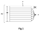
図1には、間隙なしで互いに隣り合って配置された複数本の繊維F、ここではたとえば8本の繊維Fを備えた繊維バンドFBの一実施例が示してあり、これら繊維Fはそれぞれ同じ幅BFになっている。こうした繊維は、たとえばガラス繊維、炭素繊維、アラミド繊維、又はバサルト繊維である。繊維バンドFB自体は、中央部分の直径の5%及び15%、好ましくは9%〜11%の間の全体幅BBを有する。 FIG. 1 shows an example of a fiber band FB having a plurality of fibers F arranged next to each other without a gap, for example, eight fibers F, and these fibers F are the same. It has a width of BF. Such fibers are, for example, glass fibers, carbon fibers, aramid fibers, or basalt fibers. The fiber band FB itself has an overall width BB between 5% and 15%, preferably 9% to 11% of the diameter of the central portion.
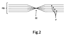
図2には、一度ねじられた繊維バンドFBの概略図が示してあり、繊維Fは、図を明瞭にするために別々の線として示されている。実際に使用される繊維バンドFBでは、繊維F同士の間の空間は存在すべきでない。ここでの、180度まで一度ねじられた繊維バンドFBの場合、繊維バンドFBの個々の繊維Fは、ねじれ部32の箇所で互いに場所が入れ替わる。ここに示すように、個々のねじれ部32は、ここでは繊維バンドFBが180度まで回転されたことを示す。たとえば、180度まで一度ねじられた繊維バンドFBの上部外側の繊維Fは、繊維バンドFBの下部外側の繊維Fになる。これに対応して、上部から2番目の繊維Fは、180度までねじられると下部から2番目の繊維Fになり、これ以降も同様になる。
FIG. 2 shows a schematic view of the fiber band FB once twisted, with the fibers F shown as separate lines for clarity. In the actually used fiber band FB, there should be no space between the fibers F. In the case of the fiber band FB once twisted up to 180 degrees, the individual fibers F of the fiber band FB are interchanged with each other at the twisted
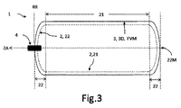
図3には、本発明による圧力容器が横断面で示してあり、この圧力容器は、円筒形の中央部分21であって、中央部分21に沿った対称軸線としてシリンダ軸線ZAを備える中央部分21と、両端部で中央部分21を閉じるドーム形状の2つの極部キャップ22とを備える内側容器2を有する。この場合、一方の極部キャップは、圧力容器1にガスを入れ、また圧力容器1からガスを出すための弁4を備える。内側容器2には、内側容器2を強化するために外側層3が巻き付けられており、この外側層3は、母材に組み込まれて互いの上に配置された繊維Fの複数の積層で作製された繊維複合材料FVMで作製されており、この積層は、複数本の繊維Fで作製された繊維バンドFB(図1及び図2を参照)として、場所依存及び位置依存の繊維配向で内側容器2の上を通っており、積層のうちの少なくともいくつかでは、繊維バンドFBは、シリンダ軸線ZAに対するそれぞれの進入繊維角度FWで中央部分21からドーム形状の極部キャップ22の領域へと進入し、そこで、その巻き方向WRにおける各反転箇所31において、中央部分22の方向に戻るように案内され、繊維バンドFBの少なくとも一部は、極部キャップ22の領域に少なくとも1つのねじれ部32を有する。中央部分21と極部キャップ22の両方での、また半径方向と軸方向に作用する力の両方に対する、外側層3の所望の全体的安定性を得るために、ここでは、外側層3は、極部キャップ22及び中央部分21を含む圧力容器1全体を被覆する複数の螺旋積層と、厚みが同一であるか又は異なる複数の周囲積層との両方を有し、周囲積層は、実質的に中央部分21に巻き付けられ、極部キャップ22の実施例に応じて、任意選択で極部キャップ22の縁部領域22rに巻き付けられる。螺旋積層は、ここでは、たとえばシリンダ軸線ZAに対して60度未満、好ましくは20度未満の小さい繊維角度FWをもつ繊維配向を備えた、軸方向に配向された繊維Fを有する。これとは対照的に、周囲積層の繊維Fは、たとえばシリンダ軸線に対して80度超の繊維角度FWをもつ繊維方向を有する。
FIG. 3 shows a pressure vessel according to the present invention in cross section, which is a cylindrical
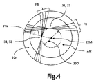
図4には、極部キャップ22の上面図において、円形ドーム形状の極部キャップ22の領域における繊維配向の概略図が示してある。対応する円筒形中央部分はここでは図示されておらず、この点に関しては図3を参照されたい。この実施例では、すべての繊維バンドFBが極部キャップ22の領域においてねじれ部32を有し、このことは、図を明瞭にするために2つの繊維バンドFBで概略的に示されている。ここに示されているねじれ部32はちょうど180度のねじれであり、図示のねじれ部32は、各繊維バンドFBの反転箇所31に配置されている。さらに、各繊維バンドFBのねじれ部32(ここでの2つの繊維バンドFBは、中央部分21から極部キャップ22への移行部において同じ進入繊維角度FWを有する)は、極部キャップ22の幾何学的中心点22Mを中心とする円33上にねじれ部の機構として配置され、円33の直径33Dは、各進入繊維角度FWにとりわけ依存する。この実施例では、さらに、他の進入繊維角度FBの別の繊維バンドFBの各ねじれ部32は、それぞれ互いに対して同心円状に、また極部キャップ22の中心点22Mを中心とする図示の円33に対して同心円状に位置することになり、このことは、図を明瞭にするためにここでは図示しない。ねじれ部32のため、外側層3の層の厚み3Dは、少なくとも極部キャップ22の中央領域22zでは、材料が積み重なることにより、ねじられた繊維バンドFBのない繊維複合層FVMの厚みよりも厚くなり、好ましくは50%を超えて厚くなる。
FIG. 4 shows a schematic view of fiber orientation in the region of the circular dome-shaped
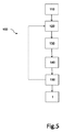
図5には、本発明による繊維強化圧力容器1を生産するための本発明による方法100の一実施例が示してあり、この方法は、対称軸線ZA、好ましくはシリンダ軸線を備える、回転対称な、好ましくは円筒形の中央部分21、及び中央部分21を閉じるドーム形状の2つの極部キャップ22を備えた内側容器2を用意するステップ110と、複数本の繊維Fで作製された繊維バンドFBを、複数の積層で、場所依存及び位置依存の繊維配向で内側容器2の中央部分21及び極部キャップに巻き付けるステップ120であって、巻付け処理の以下の個々のステップ、すなわち、積層のうちの少なくともいくつかにおいて、極部キャップ22の領域で、中央部分21から、シリンダ軸線ZAに対する各進入繊維角度FWで繊維バンドFBを進入させるステップ130、ねじれ部32を生み出すために、極部キャップ22の領域で、繊維バンドFBの少なくとも一部に関して繊維バンドFBをねじるステップ140、反転巻き方向WRにおける各反転箇所31において、繊維バンドを中央部分22の方向に戻すステップ150、及び母材に組み込まれて互いの上に配置された繊維Fの複数の積層で作製される繊維複合材料FVMで作製される圧力容器1の外側層3が完成するまで、先行する巻付けステップ120、130、140、150を繰り返すステップを有する、巻き付けるステップ120とを有する。この場合、ねじるステップ140は、極部キャップ22の領域において、繊維バンドFBのそれぞれに関してちょうど180度で実施することができる。この場合、ねじるステップ140は、反転箇所31において行われ得る。ねじるステップ140は、同じ進入繊維角度FWの各繊維バンドFBの少なくとも1つのねじれ部32が、極部キャップ22の幾何学的中心点22Mを中心とする円33上にねじれ機構として配置されるように実施することができ、円33の直径330は、各進入繊維角度FWにとりわけ依存し、好ましくは、ねじられたすべての繊維バンドFBのねじれ部32は、極部キャップ22の中心点22Mを中心に互いに対して同心円状に位置するそれぞれの円33上に配置される。この場合、ねじれ部を備える円は、互いの上に位置しないことが好ましい。これにより、第一に、ねじれ部の上に巻き付けられた繊維性材料の積層が、この場合に生じる局所的な過度の厚肉化により、下にある繊維積層との直接的な接触を失うことが防止され、したがって、それらの間の空洞なしに下にある繊維積層の上に位置する。第二に、ねじれ部のこの機構により、ドーム状極部キャップ上に生じた凹型表面プロファイルを狙い通りに埋めることが可能になり、それにより、後続の積層にとって有益な極部キャップの外形を生み出すことが可能になる。
FIG. 5 shows an embodiment of the
1 本発明による圧力容器、たとえば圧力容器
2 内側容器
21 内側容器の回転対称な中央部分、たとえば円筒形の中央部分
22 中央部分の上のドーム形状の極部キャップ
22M ドーム形状の極部キャップの幾何学的中心点
22z ドーム形状の極部キャップの中央領域
22r ドーム形状の極部キャップの縁部領域
3 繊維複合材料で作製された外側層
3D 外側層の層の厚み
31 巻き付けられた繊維配向における各繊維の反転箇所
32 極部キャップ強化層における繊維のねじれ
33 ねじれ部の円
33D ねじれ部の円の直径
4 弁
100 本発明による圧力容器の生産方法
110 圧力容器の内側容器を用意するステップ
120 内側容器に繊維バンドを巻き付けるステップ
130 中央部分から極部キャップの領域へと繊維バンドを進入させるステップ
140 極部キャップ領域において繊維バンドの少なくとも一部をねじるステップ
150 先行する巻付けステップを繰り返すステップ
BB 繊維バンドの幅
BF 繊維バンドの各繊維の幅
F 繊維複合材料の繊維
FB 複数本の繊維で作製された繊維バンド
FVM 繊維複合材料
FW 各繊維方向とシリンダ軸線の間の繊維角度、たとえば繊維バンドが中央部分から極部キャップに進入する際の進入繊維角度
ZA 対称軸線、たとえばシリンダ軸線
1 Pressure vessel according to the present invention, for example, pressure vessel 2
Claims (14)
前記内側容器(2)を強化するように前記内側容器(2)上に巻き付けられた外側層(3)であって、前記外側層(3)は、母材に埋め込まれて互いの上に配置された繊維(F)の複数の積層で作られた繊維複合材料(FVM)で作られ、前記積層は、複数の繊維(F)で作られた繊維バンド(FB)として前記内側容器(2)上にわたって場所依存及び位置依存の繊維配向で延びている、外側層(3)と
を有する繊維強化圧力容器(1)であって、
前記積層のうちの少なくともいくつかにおける前記繊維バンド(FB)が、前記対称軸線(ZA)に対するそれぞれの進入繊維角度(FW)で、前記中央部分(21)から、前記ドーム形状の極部キャップ(22)の領域へと進入し、そこで、その巻き方向(WR)におけるそれぞれの反転箇所(31)において前記中央部分(22)の方向に戻るように案内され、また前記極部キャップ(22)の前記領域に少なくとも1つのねじれ部(32)を有している、繊維強化圧力容器(1)。 A rotationally symmetric central portion (21), preferably a cylindrical central portion (21) with a symmetric axis (ZA) along the central portion (21), preferably a central portion (21) comprising a cylinder axis. And an inner container (2) with two dome-shaped pole caps (22) that close the central portion (21).
An outer layer (3) wound on the inner container (2) so as to reinforce the inner container (2), the outer layer (3) being embedded in a base material and placed on top of each other. The inner container (2) is made of a fiber composite material (FVM) made of a plurality of laminated fibers (F), and the laminated fibers are formed as a fiber band (FB) made of a plurality of fibers (F). A fiber-reinforced pressure vessel (1) with an outer layer (3) extending over it in a location-dependent and position-dependent fiber orientation.
The fiber band (FB) in at least some of the laminates, at their respective entry fiber angles (FW) with respect to the axis of symmetry (ZA), from the central portion (21) to the dome-shaped polar cap ( It enters the region of 22), where it is guided back in the direction of the central portion (22) at each reversal point (31) in its winding direction (WR), and of the pole cap (22). A fiber reinforced pressure vessel (1) having at least one twisted portion (32) in the region.
対称軸線(ZA)、好ましくはシリンダ軸線を備える、回転対称な、好ましくは円筒形の中央部分(21)、及び前記中央部分(21)を閉じるドーム形状の2つの極部キャップ(22)を備えた内側容器(2)を提供するステップ(110)と、
複数の積層内の複数の繊維(F)で作られた繊維バンド(FB)を、場所依存及び位置依存の繊維配向で前記内側容器(2)の前記中央部分(21)及び前記極部キャップの上に巻き付けるステップ(120)と
を含み、前記巻き付けるステップは、
前記積層のうちの少なくともいくつかにおける前記繊維バンド(FB)を、前記中央部分(21)から、前記極部キャップ(22)の領域において前記シリンダ軸線(ZA)に対するそれぞれの進入繊維角度(FW)で進入させるステップ(130)、
少なくとも前記積層のうちの一部の場合において、積層のすべての前記繊維バンド(FB)に関して、前記極部キャップ(22)の前記領域で前記繊維バンド(FB)をねじり、それによりねじれ部(32)を作り出すステップ(140)、
前記反転巻き方向(WR)におけるそれぞれの反転箇所(31)において、前記繊維バンドを前記中央部分(22)の方向に戻すステップ(150)、及び
母材に埋め込まれて互いの上に配置された繊維(F)の複数の積層で作られた繊維複合材料(FVM)で作られた前記圧力容器(1)の前記外側層(3)が完成するまで、先行する前記巻付けステップ(120、130、140、150)を繰り返すステップ
を含んでいる、方法。 The method (100) for manufacturing the fiber-reinforced pressure vessel (1) according to claim 1.
It has a symmetrical axis (ZA), preferably a cylinder axis, a rotationally symmetric, preferably cylindrical central portion (21), and two dome-shaped pole caps (22) that close the central portion (21). Step (110) to provide the inner container (2) and
A fiber band (FB) made of a plurality of fibers (F) in a plurality of laminates is formed in a location-dependent and position-dependent fiber orientation of the central portion (21) of the inner container (2) and the polar cap. The winding step includes a step (120) of winding on the top.
Each entry fiber angle (FW) of the fiber band (FB) in at least some of the laminates from the central portion (21) to the cylinder axis (ZA) in the region of the pole cap (22). Step to enter with (130),
For at least some of the laminates, for all the fiber bands (FBs) in the laminate, the fiber bands (FB) are twisted in the region of the pole cap (22), thereby twisting the twisted portion (32). ), Step (140),
At each reversing point (31) in the reversing winding direction (WR), the step (150) of returning the fiber band to the direction of the central portion (22), and being embedded in the base metal and arranged on each other. The winding step (120, 130) that precedes until the outer layer (3) of the pressure vessel (1) made of a fiber composite material (FVM) made of a plurality of laminates of fibers (F) is completed. , 140, 150), the method comprising repeating steps.
Applications Claiming Priority (3)
| Application Number | Priority Date | Filing Date | Title |
|---|---|---|---|
| EP17183176.1A EP3434962B1 (en) | 2017-07-26 | 2017-07-26 | Fibre-reinforced pressure vessel |
| EP17183176.1 | 2017-07-26 | ||
| PCT/EP2018/069980 WO2019020597A1 (en) | 2017-07-26 | 2018-07-24 | FIBER REINFORCED PRESSURE RESERVOIR |
Publications (2)
| Publication Number | Publication Date |
|---|---|
| JP2020528126A true JP2020528126A (en) | 2020-09-17 |
| JP7197560B2 JP7197560B2 (en) | 2022-12-27 |
Family
ID=59416547
Family Applications (1)
| Application Number | Title | Priority Date | Filing Date |
|---|---|---|---|
| JP2020504220A Active JP7197560B2 (en) | 2017-07-26 | 2018-07-24 | fiber reinforced pressure vessel |
Country Status (5)
| Country | Link |
|---|---|
| US (1) | US11585488B2 (en) |
| EP (1) | EP3434962B1 (en) |
| JP (1) | JP7197560B2 (en) |
| KR (1) | KR102639520B1 (en) |
| WO (1) | WO2019020597A1 (en) |
Families Citing this family (10)
| Publication number | Priority date | Publication date | Assignee | Title |
|---|---|---|---|---|
| EP3434962B1 (en) * | 2017-07-26 | 2022-02-23 | Nproxx B.V. | Fibre-reinforced pressure vessel |
| JP7001041B2 (en) | 2018-11-02 | 2022-02-03 | トヨタ自動車株式会社 | Manufacturing method of high pressure tank |
| US11440399B2 (en) | 2019-03-22 | 2022-09-13 | Agility Fuel Systems Llc | Fuel system mountable to a vehicle frame |
| US20200347992A1 (en) | 2019-05-02 | 2020-11-05 | Agility Fuel Systems Llc | Polymeric liner based gas cylinder with reduced permeability |
| KR102401745B1 (en) * | 2019-11-27 | 2022-05-25 | 롯데케미칼 주식회사 | High pressure tank with hoop layer and helical layer and manufacturing method thereof |
| CN113128088B (en) * | 2021-04-02 | 2022-09-20 | 华东师范大学 | Winding line type design method and system for composite material pressure container |
| US12358365B1 (en) | 2021-05-07 | 2025-07-15 | Agility Fuel Systems Llc | Vehicles having composite interwoven gas containment assemblies |
| WO2022235947A1 (en) | 2021-05-07 | 2022-11-10 | Agility Fuel Systems Llc | Composite interwoven gas containment assemblies |
| JP7583677B2 (en) * | 2021-06-17 | 2024-11-14 | 本田技研工業株式会社 | High pressure vessel and method for manufacturing the same |
| KR20250165484A (en) * | 2024-05-16 | 2025-11-26 | 현대자동차주식회사 | Pressure vessel and method of manufacturing the same |
Citations (7)
| Publication number | Priority date | Publication date | Assignee | Title |
|---|---|---|---|---|
| US3047191A (en) * | 1957-11-26 | 1962-07-31 | Hercules Powder Co Ltd | Filament wound vessels and methods for forming same |
| JPS5936146B2 (en) * | 1978-02-23 | 1984-09-01 | 川重防災工業株式会社 | pressure vessel |
| JPH0579598A (en) * | 1991-09-18 | 1993-03-30 | Eng Syst Kk | Pressure vessel |
| US5499739A (en) * | 1994-01-19 | 1996-03-19 | Atlantic Research Corporation | Thermoplastic liner for and method of overwrapping high pressure vessels |
| JP2008169893A (en) * | 2007-01-10 | 2008-07-24 | Toyota Motor Corp | Pressure vessel and method for manufacturing the same |
| WO2011045584A1 (en) * | 2009-10-13 | 2011-04-21 | Roger Carr | Fibre wound vessel |
| US8931661B2 (en) * | 2009-04-01 | 2015-01-13 | Nissan Motor Co., Ltd. | Structure and manufacturing method for pressure vessel |
Family Cites Families (12)
| Publication number | Priority date | Publication date | Assignee | Title |
|---|---|---|---|---|
| US2109529A (en) * | 1936-12-21 | 1938-03-01 | Robert H Goddard | Reenforced construction for light hollow members |
| US3282757A (en) * | 1962-12-14 | 1966-11-01 | Structural Fibers | Method of making a filament reinforced pressure vessel |
| GB1130637A (en) * | 1966-04-01 | 1968-10-16 | Metal Containers Ltd | Filament wound vessel |
| AU2002319973A1 (en) * | 2002-08-08 | 2004-02-25 | Technische Universiteit Delft | Pressurizable structures comprising different surface sections |
| US9939108B2 (en) * | 2007-10-16 | 2018-04-10 | WireTough Cylinders, LLC | Wire wrapped pressure vessels |
| US8074826B2 (en) * | 2008-06-24 | 2011-12-13 | Composite Technology Development, Inc. | Damage and leakage barrier in all-composite pressure vessels and storage tanks |
| DE202016100754U1 (en) * | 2016-02-12 | 2016-02-23 | Enrichment Technology Company Ltd. Zweigniederlassung Deutschland | Polkappenverstärkter pressure vessel |
| JP6729472B2 (en) * | 2017-04-20 | 2020-07-22 | 株式会社豊田自動織機 | Fiber structure, pressure vessel, and method for manufacturing fiber structure |
| DE102017208492B4 (en) * | 2017-05-19 | 2020-07-30 | Nproxx B.V. | Pole cap reinforced pressure vessel |
| US10240723B2 (en) * | 2017-05-31 | 2019-03-26 | Siargo Ltd. | Digital regulated gas dispensing apparatus with a MEMS mass flow meter |
| JP6908782B2 (en) * | 2017-06-12 | 2021-07-28 | インテグリス・インコーポレーテッド | Thermochromic indicator for reagent gas vessels |
| EP3434962B1 (en) * | 2017-07-26 | 2022-02-23 | Nproxx B.V. | Fibre-reinforced pressure vessel |
-
2017
- 2017-07-26 EP EP17183176.1A patent/EP3434962B1/en active Active
-
2018
- 2018-07-24 JP JP2020504220A patent/JP7197560B2/en active Active
- 2018-07-24 US US16/633,798 patent/US11585488B2/en active Active
- 2018-07-24 KR KR1020207003365A patent/KR102639520B1/en active Active
- 2018-07-24 WO PCT/EP2018/069980 patent/WO2019020597A1/en not_active Ceased
Patent Citations (7)
| Publication number | Priority date | Publication date | Assignee | Title |
|---|---|---|---|---|
| US3047191A (en) * | 1957-11-26 | 1962-07-31 | Hercules Powder Co Ltd | Filament wound vessels and methods for forming same |
| JPS5936146B2 (en) * | 1978-02-23 | 1984-09-01 | 川重防災工業株式会社 | pressure vessel |
| JPH0579598A (en) * | 1991-09-18 | 1993-03-30 | Eng Syst Kk | Pressure vessel |
| US5499739A (en) * | 1994-01-19 | 1996-03-19 | Atlantic Research Corporation | Thermoplastic liner for and method of overwrapping high pressure vessels |
| JP2008169893A (en) * | 2007-01-10 | 2008-07-24 | Toyota Motor Corp | Pressure vessel and method for manufacturing the same |
| US8931661B2 (en) * | 2009-04-01 | 2015-01-13 | Nissan Motor Co., Ltd. | Structure and manufacturing method for pressure vessel |
| WO2011045584A1 (en) * | 2009-10-13 | 2011-04-21 | Roger Carr | Fibre wound vessel |
Also Published As
| Publication number | Publication date |
|---|---|
| EP3434962A1 (en) | 2019-01-30 |
| US20210088183A1 (en) | 2021-03-25 |
| KR20200037786A (en) | 2020-04-09 |
| JP7197560B2 (en) | 2022-12-27 |
| KR102639520B1 (en) | 2024-02-22 |
| EP3434962B1 (en) | 2022-02-23 |
| US11585488B2 (en) | 2023-02-21 |
| WO2019020597A1 (en) | 2019-01-31 |
Similar Documents
| Publication | Publication Date | Title |
|---|---|---|
| JP2020528126A (en) | Fiber reinforced pressure vessel | |
| ES2974306T3 (en) | Cap-reinforced pressure vessel | |
| KR102240301B1 (en) | Pressure vessel and manufacturing method thereof | |
| EP3479004B1 (en) | Pressure vessel with a tape-based reinforcement structure | |
| JP6994829B2 (en) | High pressure container | |
| JP6623722B2 (en) | High pressure tank | |
| JPWO2011154994A1 (en) | High-pressure tank and method for manufacturing high-pressure tank | |
| KR20240005680A (en) | Composite interwoven gas encapsulation assembly | |
| JP7439744B2 (en) | High pressure tank and its manufacturing method | |
| US20180104916A1 (en) | Composite container | |
| US20210404603A1 (en) | Compressed gas storage unit with preformed endcaps | |
| JP2015209887A (en) | Pressure container | |
| EP3691878B1 (en) | Pressure vessel and method for forming an outer layer of a pressure vessel | |
| KR101846733B1 (en) | Pressure vessel using fiber-reinforced composite and method manufacturing thereof | |
| CN106460985B (en) | torsionally loaded rod-shaped member | |
| JP7093010B2 (en) | High pressure tank | |
| KR20180111728A (en) | High pressure tank | |
| CN203453652U (en) | Pressure pipe formed by hot winding of composite winding strips | |
| JP2019019954A (en) | Manufacturing method of high-pressure tank | |
| CN115059870B (en) | Three-dimensional integrally woven hydrogen storage bottle and manufacturing method thereof | |
| JP2020131430A (en) | How to make a high pressure tank | |
| JP2020020392A (en) | Pressure vessel and method of manufacturing pressure vessel | |
| US11506335B2 (en) | Tank liner having two cylindrical sections |
Legal Events
| Date | Code | Title | Description |
|---|---|---|---|
| A621 | Written request for application examination |
Free format text: JAPANESE INTERMEDIATE CODE: A621 Effective date: 20210705 |
|
| A131 | Notification of reasons for refusal |
Free format text: JAPANESE INTERMEDIATE CODE: A131 Effective date: 20220317 |
|
| A521 | Request for written amendment filed |
Free format text: JAPANESE INTERMEDIATE CODE: A523 Effective date: 20220616 |
|
| A131 | Notification of reasons for refusal |
Free format text: JAPANESE INTERMEDIATE CODE: A131 Effective date: 20220705 |
|
| A521 | Request for written amendment filed |
Free format text: JAPANESE INTERMEDIATE CODE: A523 Effective date: 20220926 |
|
| TRDD | Decision of grant or rejection written | ||
| A01 | Written decision to grant a patent or to grant a registration (utility model) |
Free format text: JAPANESE INTERMEDIATE CODE: A01 Effective date: 20221202 |
|
| A61 | First payment of annual fees (during grant procedure) |
Free format text: JAPANESE INTERMEDIATE CODE: A61 Effective date: 20221215 |
|
| R150 | Certificate of patent or registration of utility model |
Ref document number: 7197560 Country of ref document: JP Free format text: JAPANESE INTERMEDIATE CODE: R150 |
|
| R250 | Receipt of annual fees |
Free format text: JAPANESE INTERMEDIATE CODE: R250 |