JP2021034603A - Power conversion device - Google Patents
Power conversion device Download PDFInfo
- Publication number
- JP2021034603A JP2021034603A JP2019154529A JP2019154529A JP2021034603A JP 2021034603 A JP2021034603 A JP 2021034603A JP 2019154529 A JP2019154529 A JP 2019154529A JP 2019154529 A JP2019154529 A JP 2019154529A JP 2021034603 A JP2021034603 A JP 2021034603A
- Authority
- JP
- Japan
- Prior art keywords
- housing
- support recess
- conversion device
- power conversion
- rotation shaft
- Prior art date
- Legal status (The legal status is an assumption and is not a legal conclusion. Google has not performed a legal analysis and makes no representation as to the accuracy of the status listed.)
- Granted
Links
Images



Landscapes
- Pivots And Pivotal Connections (AREA)
- Casings For Electric Apparatus (AREA)
- Inverter Devices (AREA)
Abstract
【課題】筐体に取り付けられたカバー部材に筐体の外側に向かって大きな圧力が加わった際に、カバー部材が筐体から外れて落下してしまうのを抑制することが可能な電力変換装置を提供する。【解決手段】この電力変換装置100は、開口部33を覆うとともに、筐体30に対して着脱可能に取り付けられる点検カバー31と、を備えている。そして、点検カバー31側には、点検カバー31を筐体30に対して回動させるための回動軸52が設けられており、筐体30側には、回動軸52が嵌り込むように、かつ、回動軸52を回動可能に支持するように、下方(Z2側)に窪んだ支持凹部61が設けられている。【選択図】図7PROBLEM TO BE SOLVED: To prevent a cover member from falling off the housing when a large pressure is applied to the cover member attached to the housing toward the outside of the housing. I will provide a. A power conversion device 100 covers an opening 33 and includes an inspection cover 31 that is detachably attached to a housing 30. A rotation shaft 52 for rotating the inspection cover 31 with respect to the housing 30 is provided on the inspection cover 31 side, and the rotation shaft 52 is fitted on the housing 30 side. In addition, a support recess 61 recessed downward (Z2 side) is provided so as to rotatably support the rotation shaft 52. [Selection diagram] FIG. 7
Description
この発明は、電力変換装置に関し、特に、筐体に対して着脱可能に取り付けられるカバー部材を備える電力変換装置に関する。 The present invention relates to a power conversion device, and more particularly to a power conversion device including a cover member that is detachably attached to a housing.
従来、筐体に対して着脱可能に取り付けられるカバー部材を備える電力変換装置が開示されている(たとえば、特許文献1参照)。 Conventionally, a power conversion device including a cover member that can be detachably attached to a housing has been disclosed (see, for example, Patent Document 1).
上記特許文献1には、鉄道車両の床下に設けられ、筐体に対して着脱可能に取り付けられる点検カバー(カバー部材)を備えた電力変換装置が記載されている。上記特許文献1に記載の電力変換装置では、筐体に対して点検カバーが取り付けられることによって、筐体の内部が密閉されるように構成されている。上記特許文献1に記載の電力変換装置は、点検カバーに固定されるとともに先端が半円状に曲げられたフックと、筐体側に設けられるとともに水平方向に延びるピン(軸)と、を備えている。そして、上記特許文献1に記載の電力変換装置では、点検カバーの筐体に対する取付けおよび取外しの際に、点検カバーを筐体に対してピン(軸)を中心に回動可能なように、フックがピンに対して筐体の外側から、かつ、上方から引っ掛けられている。なお、上記特許文献1に記載の電力変換装置では、掛け代(フックをピンに引っ掛けた際のフックがピンに引っ掛っている鉛直方向における距離)は、ピンの半径程度となっている。また、上記特許文献1に記載の電力変換装置では、フックの先端は、斜め下方に筐体側に向かっている。 The above-mentioned Patent Document 1 describes a power conversion device provided under the floor of a railway vehicle and provided with an inspection cover (cover member) that is detachably attached to a housing. The power conversion device described in Patent Document 1 is configured so that the inside of the housing is sealed by attaching an inspection cover to the housing. The power conversion device described in Patent Document 1 includes a hook fixed to an inspection cover and a semicircular tip, and a pin (shaft) provided on the housing side and extending in the horizontal direction. There is. Then, in the power conversion device described in Patent Document 1, when the inspection cover is attached to and removed from the housing, the inspection cover is hooked so as to be rotatable about a pin (axis) with respect to the housing. Is hooked on the pin from the outside of the housing and from above. In the power conversion device described in Patent Document 1, the hooking allowance (distance in the vertical direction in which the hook is hooked on the pin when the hook is hooked on the pin) is about the radius of the pin. Further, in the power conversion device described in Patent Document 1, the tip of the hook is obliquely downward toward the housing side.
ここで、上記特許文献1には記載されていないが、上記特許文献1に記載のような従来の電力変換装置では、電力変換回路における電圧を平滑化するためのフィルタコンデンサとして、絶縁油が気密封止されたオイルコンデンサが設けられる場合がある。この場合、オイルコンデンサへの高電圧の印加やオイルコンデンサが経年劣化するのに伴って、気密封入された絶縁油から発生するガスの圧力によって、オイルコンデンサが破裂する場合がある。そして、オイルコンデンサが破裂した場合、カバー部材が取り付けられることによって密閉された筐体の内部の圧力が急激に上昇して、筐体に取り付けられたカバー部材に筐体の外側(側方)に向かって圧力が加わる。なお、筐体が密閉されていない場合でも、筐体に内蔵されている部品が脱落、破裂すること等によって、飛散した部品、または、その一部がカバー部材に衝突した場合、カバー部材に筐体の外側(側方)に向かって圧力が加わる。しかしながら、上記特許文献1に記載のような従来の電力変換装置では、フックは、ピンに対して筐体の外側から、かつ、上方から引っ掛けられているとともに、掛け代がピンの半径程度となっているので、筐体に取り付けられたカバー部材に筐体の外側(側方)に向かって大きな圧力が加わった際に、カバー部材に固定されたフックがピンから容易に外れてしまうと考えられる。そして、フックがピンから外れた場合、フックが固定されたカバー部材が筐体から外れて落下する。 Here, although not described in Patent Document 1, in the conventional power conversion device as described in Patent Document 1, insulating oil is used as a filter capacitor for smoothing the voltage in the power conversion circuit. A tightly sealed oil condenser may be provided. In this case, the oil capacitor may explode due to the pressure of the gas generated from the air-sealed insulating oil as the high voltage is applied to the oil capacitor or the oil capacitor deteriorates over time. Then, when the oil condenser ruptures, the pressure inside the sealed housing rapidly rises due to the attachment of the cover member, and the cover member attached to the housing is attached to the outside (side) of the housing. Pressure is applied toward. Even if the housing is not hermetically sealed, if the parts built into the housing fall off or burst, and if the scattered parts or a part of them collide with the cover member, the housing will be placed in the cover member. Pressure is applied toward the outside (side) of the body. However, in the conventional power conversion device as described in Patent Document 1, the hook is hooked to the pin from the outside of the housing and from above, and the hooking allowance is about the radius of the pin. Therefore, it is considered that the hook fixed to the cover member is easily disengaged from the pin when a large pressure is applied to the cover member attached to the housing toward the outside (side) of the housing. .. Then, when the hook comes off the pin, the cover member to which the hook is fixed comes off from the housing and falls.
そこで、上記特許文献1には記載されていないが、上記特許文献1に記載のような従来の電力変換装置において、フックの半円状に曲げられた部分から更に延びる部分(延長部分)を設けることにより、掛け代を大きくすることが考えられる。この場合、延長部分は、斜め下方に筐体側に向かって延びるので、フックの延長部分が、カバー部材の筐体に対する着脱の際に、筐体に接触する場合がある。すなわち、上記特許文献1に記載のような従来の電力変換装置では、掛け代を大きくすることが比較的難しい。このため、上記特許文献1に記載のような従来の電力変換装置では、筐体に取り付けられたカバー部材に筐体の外側に向かって大きな圧力が加わった際に、カバー部材が筐体から外れて落下し易いという問題点がある。 Therefore, although not described in Patent Document 1, in the conventional power conversion device as described in Patent Document 1, a portion (extension portion) further extending from the semicircularly bent portion of the hook is provided. As a result, it is conceivable to increase the hanging allowance. In this case, since the extension portion extends diagonally downward toward the housing side, the extension portion of the hook may come into contact with the housing when the cover member is attached to or detached from the housing. That is, in the conventional power conversion device as described in Patent Document 1, it is relatively difficult to increase the multiplication allowance. Therefore, in the conventional power conversion device as described in Patent Document 1, when a large pressure is applied to the cover member attached to the housing toward the outside of the housing, the cover member comes off from the housing. There is a problem that it is easy to fall.
この発明は、上記のような課題を解決するためになされたものであり、この発明の1つの目的は、筐体に取り付けられたカバー部材に筐体の外側に向かって大きな圧力が加わった際に、カバー部材が筐体から外れて落下してしまうのを抑制することが可能な電力変換装置を提供することである。 The present invention has been made to solve the above problems, and one object of the present invention is when a large pressure is applied to the cover member attached to the housing toward the outside of the housing. In addition, it is an object of the present invention to provide a power conversion device capable of suppressing the cover member from falling off the housing.
上記目的を達成するために、この発明の一の局面による電力変換装置は、開口部が形成された筐体と、開口部を覆うとともに、筐体に対して着脱可能に取り付けられるカバー部材と、を備え、カバー部材側には、カバー部材を筐体に対して回動させるための回動軸が設けられており、筐体側には、回動軸が嵌り込むように、かつ、回動軸を回動可能に支持するように、下方に窪んだ支持凹部が設けられている。 In order to achieve the above object, the power conversion device according to one aspect of the present invention includes a housing in which an opening is formed, a cover member that covers the opening and is detachably attached to the housing. On the cover member side, a rotation shaft for rotating the cover member with respect to the housing is provided, and on the housing side, the rotation shaft is fitted and the rotation shaft is provided. Is provided with a downwardly recessed support recess so as to rotatably support the.
この発明の一の局面による電力変換装置では、上記のように、カバー部材側には、カバー部材を筐体に対して回動させるための回動軸が設けられており、筐体側には、回動軸が嵌り込むように、かつ、回動軸を回動可能に支持するように、下方に窪んだ支持凹部が設けられている。これにより、回動軸が嵌り込むように下方に窪んだ支持凹部の深さが、掛け代(回動軸を支持凹部に嵌め込んだ際の回動軸が支持凹部に引っ掛っている鉛直方向における距離)となるので、支持凹部の深さを深くすることによって、カバー部材側に設けられた回動軸が筐体側に設けられた支持凹部から外れにくくなるように、掛け代を大きくすることができる。すなわち、フックに延長部分を設ける場合のように、筐体側に向かって延びる部分が生じないので、カバー部材の筐体に対する着脱の際に、筐体に接触する部分が生じるのを抑制しながら、掛け代を大きくすることができる。その結果、筐体に取り付けられたカバー部材に筐体の外側(側方)に向かって大きな圧力が加わった際に、カバー部材が筐体から外れて落下してしまうのを抑制することができる。 In the power conversion device according to one aspect of the present invention, as described above, the cover member side is provided with a rotation shaft for rotating the cover member with respect to the housing, and the housing side is provided with a rotation shaft. A support recess recessed downward is provided so that the rotating shaft can be fitted and the rotating shaft can be rotatably supported. As a result, the depth of the support recess that is recessed downward so that the rotation shaft fits into is the hooking allowance (the vertical direction in which the rotation shaft is hooked on the support recess when the rotation shaft is fitted into the support recess). By increasing the depth of the support recess, the hooking allowance should be increased so that the rotation shaft provided on the cover member side does not easily come off from the support recess provided on the housing side. Can be done. That is, unlike the case where the hook is provided with an extension portion, a portion extending toward the housing side does not occur, so that when the cover member is attached to or detached from the housing, a portion that comes into contact with the housing is suppressed. The hooking allowance can be increased. As a result, when a large pressure is applied to the cover member attached to the housing toward the outside (side) of the housing, it is possible to prevent the cover member from falling off the housing. ..
上記一の局面による電力変換装置において、好ましくは、支持凹部の深さは、回動軸の半径よりも大きい。このように構成すれば、掛け代(回動軸を支持凹部に嵌め込んだ際の回動軸が支持凹部に引っ掛っている鉛直方向における距離)が回動軸の半径よりも大きくなるので、支持凹部の深さが回動軸の半径以下の場合と比較して、回動軸が支持凹部から外れてしまうのを抑制することができる。 In the power conversion device according to the above one aspect, preferably, the depth of the support recess is larger than the radius of the rotation shaft. With this configuration, the hooking allowance (distance in the vertical direction in which the rotation shaft is hooked on the support recess when the rotation shaft is fitted into the support recess) is larger than the radius of the rotation shaft. Compared with the case where the depth of the support recess is less than the radius of the rotation shaft, it is possible to prevent the rotation shaft from coming off the support recess.
この場合、好ましくは、支持凹部の深さは、回動軸の直径よりも大きい。このように構成すれば、掛け代が回動軸の直径よりも大きくなるので、支持凹部の深さが回動軸の半径よりも大きく、かつ、直径以下の場合と比較して、回動軸が支持凹部から外れてしまうのをより抑制することができる。 In this case, preferably, the depth of the support recess is larger than the diameter of the rotating shaft. With this configuration, the hooking allowance is larger than the diameter of the rotating shaft, so that the depth of the support recess is larger than the radius of the rotating shaft and is smaller than the diameter of the rotating shaft. Can be more suppressed from coming off from the support recess.
上記一の局面による電力変換装置において、好ましくは、支持凹部は、回動軸が延びる方向に互いに離間するように一対設けられており、回動軸は、一対の支持凹部により支持されている。このように構成すれば、回動軸を、回動軸が延びる方向に互いに離間するように設けられた一対の支持凹部により、安定して支持することができる。 In the power conversion device according to the above one aspect, preferably, a pair of support recesses are provided so as to be separated from each other in the direction in which the rotation shafts extend, and the rotation shafts are supported by the pair of support recesses. With this configuration, the rotating shafts can be stably supported by a pair of supporting recesses provided so as to be separated from each other in the direction in which the rotating shafts extend.
上記一の局面による電力変換装置において、好ましくは、支持凹部は、筐体側とは反対側の上端部の高さ位置が、筐体側の上端部の高さ位置よりも低くなるように構成されている。このように構成すれば、支持凹部の筐体側とは反対側の上端部の高さ位置が過度に高くなるのを抑制することができるので、回動軸の支持凹部に対する取り付けおよび取り外しのために、回動軸(カバー部材)を上方に持ち上げる高さが過度に大きくなるのを抑制することができる。また、回動軸を、筐体側とは反対側の上端部の高さ位置の直上において、筐体側とは反対側から筐体側に向かって支持凹部の筐体側に接触するまで近付けて、下方に移動させることによって、回動軸を支持凹部に嵌め込むことができるので、回動軸を支持凹部に対して容易に取り付けることができる。 In the power conversion device according to the above one aspect, preferably, the support recess is configured so that the height position of the upper end portion on the side opposite to the housing side is lower than the height position of the upper end portion on the housing side. There is. With this configuration, it is possible to prevent the height position of the upper end portion of the support recess on the side opposite to the housing side from becoming excessively high, so that the rotation shaft can be attached to and removed from the support recess. , It is possible to prevent the height at which the rotating shaft (cover member) is lifted from becoming excessively large. Further, the rotating shaft is moved downward from the side opposite to the housing side until it comes into contact with the housing side of the support recess toward the housing side, just above the height position of the upper end portion on the side opposite to the housing side. By moving the rotating shaft, the rotating shaft can be fitted into the supporting recess, so that the rotating shaft can be easily attached to the supporting recess.
上記一の局面による電力変換装置において、好ましくは、支持凹部の内側面は、鉛直下方から鉛直上方に向かうにしたがって、筐体側とは反対側から筐体側に向かって傾斜するように形成されている。このように構成すれば、回動軸に対して、鉛直上方の力に加えて、筐体の内側に向かう方向の力が作用しない限り、回動軸が支持凹部から外れないようにすることができる。なお、筐体の内部の圧力が急激に上昇した際にカバー部材に作用する圧力は、筐体の外側(側方)に向かう方向の成分が主であり、筐体の内側に向かう方向の成分を殆ど含まない。その結果、支持凹部の内側面が、鉛直下方から鉛直上方に向かうにしたがって、筐体側とは反対側から筐体側に向かって傾斜していない場合と比較して、カバー部材に圧力が加わった際に回動軸を支持凹部から外れ難くすることができる。 In the power conversion device according to the above one aspect, preferably, the inner surface of the support recess is formed so as to incline from the side opposite to the housing side toward the housing side from vertically below to vertically above. .. With this configuration, the rotating shaft can be prevented from coming off the support recess unless a force in the direction toward the inside of the housing is applied to the rotating shaft in addition to a vertically upward force. it can. The pressure acting on the cover member when the pressure inside the housing suddenly rises is mainly a component in the direction toward the outside (side) of the housing, and a component in the direction toward the inside of the housing. Almost no. As a result, when pressure is applied to the cover member as compared with the case where the inner surface of the support recess is not inclined from the side opposite to the housing side toward the housing side from the vertically lower side to the vertically upper side. The rotating shaft can be made difficult to come off from the support recess.
上記一の局面による電力変換装置において、好ましくは、支持凹部は、回動軸の形状に対応するように、半円形状の下端部を有する。このように構成すれば、回動軸が支持凹部に嵌り込んだ状態で、回動軸を容易に回動させることができるので、カバー部材の筐体に対する取付けおよび取外しの際に、カバー部材を筐体に対して容易に回動させることができる。 In the power conversion device according to the above one aspect, the support recess preferably has a semicircular lower end portion corresponding to the shape of the rotating shaft. With this configuration, the rotating shaft can be easily rotated while the rotating shaft is fitted in the support recess, so that the cover member can be mounted and removed from the housing when the cover member is attached to and removed from the housing. It can be easily rotated with respect to the housing.
上記一の局面による電力変換装置において、好ましくは、筐体のカバー部材が設けられる側の面から突出するとともに、支持凹部が設けられている突出部材と、回動軸と筐体の内部を密閉するためのカバー部材とに接続する接続部材と、をさらに備え、接続部材は、カバー部材から回動軸に向かうにしたがって、筐体側から筐体側とは反対側に向かって傾斜する部分を含むように形成されている。このように構成すれば、回動軸とカバー部材とに接続する接続部材が、筐体側から筐体側とは反対側に向かって傾斜する部分を含むので、接続部材に接続された回動軸の位置を、筐体のカバー部材が設けられる側の面から筐体側とは反対側に離間した位置に容易に配置することができる。その結果、筐体のカバー部材が設けられる側の面から突出している突出部材に設けられている支持凹部に、接続部材に接続された回動軸を容易に嵌め込むことできる。 In the power conversion device according to the above one aspect, preferably, the projecting member is projected from the surface on the side where the cover member of the housing is provided, and the rotating shaft and the inside of the housing are sealed with the protruding member provided with the support recess. A connecting member for connecting to the cover member for connecting the cover member is further provided, and the connecting member includes a portion that inclines from the housing side toward the side opposite to the housing side as the cover member moves toward the rotation axis. Is formed in. With this configuration, the connecting member connected to the rotating shaft and the cover member includes a portion that is inclined from the housing side to the side opposite to the housing side, so that the rotating shaft connected to the connecting member The position can be easily arranged at a position separated from the surface on the side where the cover member of the housing is provided on the side opposite to the housing side. As a result, the rotating shaft connected to the connecting member can be easily fitted into the support recess provided in the protruding member protruding from the surface on the side where the cover member of the housing is provided.
上記一の局面による電力変換装置において、好ましくは、鉄道車両に搭載される電力変換装置であって、開口部は、筐体の鉄道車両の走行方向または走行方向と直交する方向における側面に形成されており、カバー部材は、筐体の側面に形成された開口部を覆うように、筐体に対して着脱可能に取り付けられている。このように構成すれば、鉄道車両に設けられる電力変換装置は、フィルタコンデンサとして(経年劣化に伴って破裂する場合がある)オイルコンデンサが使用されることが一般的なので、筐体に取り付けられたカバー部材に大きな圧力が加わった際に、カバー部材が筐体から外れて落下してしまうのを抑制することが可能な構成を効果的に適用することができる。また、開口部が筐体の鉄道車両の走行方向または走行方向と直交する方向における側面に形成されているので、メンテナンス(点検)時の作業性を向上させることができる。 In the power conversion device according to the above one aspect, preferably, it is a power conversion device mounted on a railroad vehicle, and an opening is formed in a traveling direction of the housing or a side surface in a direction orthogonal to the traveling direction. The cover member is detachably attached to the housing so as to cover the opening formed on the side surface of the housing. With this configuration, the power converter installed in a railroad vehicle is generally attached to a housing because an oil capacitor (which may explode due to aging) is generally used as a filter capacitor. It is possible to effectively apply a configuration capable of suppressing the cover member from falling off the housing when a large pressure is applied to the cover member. Further, since the opening is formed on the side surface of the housing in the traveling direction or the direction orthogonal to the traveling direction of the railway vehicle, the workability at the time of maintenance (inspection) can be improved.
本発明によれば、上記のように、筐体に取り付けられたカバー部材に筐体の外側に向かって大きな圧力が加わった際に、カバー部材が筐体から外れて落下してしまうのを抑制することができる。 According to the present invention, as described above, when a large pressure is applied to the cover member attached to the housing toward the outside of the housing, the cover member is prevented from falling off the housing. can do.
以下、本発明を具体化した実施形態を図面に基づいて説明する。 Hereinafter, embodiments embodying the present invention will be described with reference to the drawings.
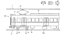
図1〜図13を参照して、本発明の一実施形態による電力変換装置100の構成について説明する。電力変換装置100は、鉄道車両10に搭載される電力変換装置である。
The configuration of the
図1に示すように、鉄道車両10は、架線1から供給される電力(直流電源)により、レール2上を走行するように構成されている。以下の説明では、鉄道車両10の走行方向、鉄道車両10の走行方向と直交する枕木方向、および、鉄道車両10の上下方向を、それぞれ、X方向、Y方向およびZ方向とする。また、鉄道車両10の上側(上方向)および下側(下方向)を、それぞれ、Z1側(Z1方向)およびZ2側(Z2方向)とする。なお、「枕木方向」の「枕木」とは、レール2の下にレール2と直交するように敷かれ、レール2を支える部材である。
As shown in FIG. 1, the
鉄道車両10は、車体11と、パンタグラフ12と、駆動輪13を回転させる誘導電動機14と、空調機器や制御機器等のその他の機器類15と、電力変換装置100と、を備えている。車体11の底部11aの下側(Z2側)には、電力変換装置100が取り付けられている。パンタグラフ12は、架線1に供給されている電力を受電(集電)する。電力変換装置100は、鉄道車両10の走行時に、架線1からの電力を半導体スイッチング素子21(図2参照)のスイッチングにより変換して、誘導電動機14の回転制御を行う。
The
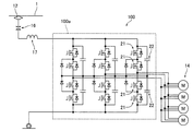
図2に示すように、パンタグラフ12から、遮断器16、リアクトル17を介して、電力変換装置100に直流電圧が入力される。電力変換装置100は、インバータ部100aを備えている。インバータ部100aは、架線1から入力される直流電圧を、交流電圧に変換する。そして、変換された交流電圧が、インバータ部100aから、鉄道車両10を駆動するための誘導電動機14に出力される。
As shown in FIG. 2, a DC voltage is input from the
インバータ部100aは、半導体スイッチング素子21と、オイルコンデンサ22と、を含む。半導体スイッチング素子21は、シリコン(Si)半導体からなるMOSFET(Metal Oxide Semiconductor Field Effect Transistor)である。オイルコンデンサ22は、インバータ部100aの入力電圧を平滑化するためのフィルタコンデンサとして設けられている。オイルコンデンサ22は、ケース内に、コンデンサ素子が収納されるとともに、絶縁油が充填されて気密封止されている。
The
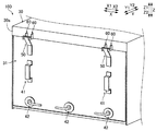
図3に示すように、電力変換装置100は、筐体30と、点検カバー31と、を備えている。なお、点検カバー31は、特許請求の範囲の「カバー部材」の一例である。
As shown in FIG. 3, the
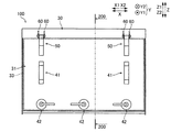
筐体30には、オイルコンデンサ22等を含むインバータ部100aが内蔵(収納)されている。筐体30には、メンテナンス用(点検用)の開口部33(図4参照)が形成されている。図4に示すように、開口部33は、筐体30の枕木方向(Y方向)における側面30aに形成されている。以下の説明では、筐体30の開口部33が設けられる側、および、筐体30の開口部33が設けられる側とは反対側を、それぞれ、Y1側およびY2側とする。なお、側面30aは、特許請求の範囲の「筐体の(カバー部材が設けられる側の)面」の一例である。
An
図5に示すように、開口部33の外周部には、シール部材34が設けられている。シール部材34は、開口部33の外周部に沿って、略環状に配置されている。なお、図5では、Z1側およびZ2側のシール部材34のみを図示している。
As shown in FIG. 5, a sealing
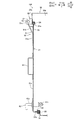
点検カバー31は、筐体30の内部30bが密閉されるように、筐体30のY1側の側面30aに形成された開口部33を覆うように筐体30に対して取り付けられている。具体的には、点検カバー31が筐体30に対して取り付けられた状態において、点検カバー31の外周部が、シール部材34に当接するように構成されている。図5では、点検カバー31の上側(Z1側)の端部31aおよび下側(Z2側)の端部31bが、シール部材34に当接した状態を図示している。なお、後述するように、点検カバー31は、筐体30に対して着脱可能に取り付けられている。
The
図3に示すように、点検カバー31には、把持部材41と、カバー固定部材42と、が取り付けられている。
As shown in FIG. 3, a gripping
把持部材41は、インバータ部100aのメンテナンスが行われる際に、作業者が把持するための取手である。図4に示すように、把持部材41は、点検カバー31のZ方向における中央部に取り付けられている。図5に示すように、把持部材41は、点検カバー31の外側(筐体30側とは反対側(Y1側))の面31cに溶接等によって取り付けられている。
The gripping
図3に示すように、カバー固定部材42は、点検カバー31が筐体30の開口部33を覆った状態で、点検カバー31を筐体30に対して固定するための部材である。カバー固定部材42は、図4に示すように、点検カバー31のZ方向における下部に取り付けられている。図5に示すように、カバー固定部材42は、レバー部42aと、引掛かり部42bと、を含む。レバー部42aは、点検カバー31の外側(筐体30側とは反対側(Y1側))に配置されている。引掛かり部42bは、点検カバー31の内側(筐体30側(Y2側))に配置されている。カバー固定部材42は、レバー部42aを回動させると、レバー部42aの回動角度に応じた角度だけ、引掛かり部42bが回動するように構成されている。
As shown in FIG. 3, the
ここで、本実施形態では、点検カバー31側には、点検カバー31を筐体30に対して回動させるための回動軸52が設けられている。また、筐体30側には、回動軸52が嵌り込むように、かつ、回動軸52を回動可能に支持するように、下方(Z2側)に窪んだ支持凹部61が設けられている。
Here, in the present embodiment, a
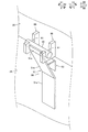
具体的には、図3に示すように、電力変換装置100は、カバー回動用部材50と、回動軸支持部材60と、を備えている。なお、回動軸支持部材60は、特許請求の範囲の「突出部材」の一例である。
Specifically, as shown in FIG. 3, the
カバー回動用部材50は、点検カバー31の上部の筐体30側とは反対側(Y1側)に配置されている。カバー回動用部材50は、点検カバー31に対して一対設けられている。一対の点検カバー31は、互いに、X方向に離間して配置されている。
The
図6に示すように、カバー回動用部材50は、平板形状を有する板状部材51と、円柱形状を有する回動軸52と、から構成されている。板状部材51は、固定部51aと、斜面部51bと、を含む。なお、板状部材51は、特許請求の範囲の「接続部材」の一例である。また、斜面部51bは、特許請求の範囲の「接続部材の筐体側から筐体側とは反対側に向かって傾斜する部分」の一例である。
As shown in FIG. 6, the
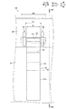
固定部51aは、点検カバー31の上部において、点検カバー31と略平行に配置された状態で、点検カバー31に対して溶接等によって取り付けられている。図7に示すように、固定部51aは、X方向において、幅W1を有する。
The fixed
図6に示すように、回動軸52は、固定部51aよりも上方(Z1側)に配置されている。また、回動軸52は、固定部51aよりも筐体30から筐体30側とは反対側(Y1側)に離れた位置に配置されている。図6に示すように、回動軸52は、X方向において、(固定部51aの幅W1よりも大きい)幅W2を有する。
As shown in FIG. 6, the rotating
斜面部51bは、X方向において、(固定部51aの幅W1と等しい)幅W1を有する。図8に示すように、斜面部51bは、点検カバー31から回動軸52に向かうにしたがって、筐体30側(Y2側)から筐体30側とは反対側(Y1側)に向かって傾斜するように形成されている。そして、斜面部51bは、下側(Z2側)において、固定部51aの上端部と接続されるとともに、上側(Z1側)において、回動軸52と溶接等によって固定(接続)されている。なお、斜面部51bの上側の端部51cは、固定部51aと略平行となるように、折り曲げられている。すなわち、斜面部51bは、斜面部51bと回動軸52とが当接する面積(箇所)を大きくして、斜面部51bと回動軸52との溶接等による固定が容易となるように、折り曲げられている。
The
図6に示すように、斜面部51bの筐体30側には、補強板53が設けられている。図8に示すように、補強板53は、点検カバー31の面31cと略平行に配置された部分53aと、部分53aと略垂直に配置された部分53bと、を含む。部分53aは、点検カバー31の面31cに対して溶接等によって固定されている。部分53bの筐体30側とは反対側(Y1側)の端部は、斜面部51bと当接している。
As shown in FIG. 6, a reinforcing
回動軸支持部材60は、筐体30の点検カバー31が設けられる側(Y1側)の側面30aから突出するように筐体30に取り付けられている。回動軸支持部材60は、筐体30の側面30aにおいて、開口部33の直上に設けられている。回動軸支持部材60には、支持凹部61が設けられている。支持凹部61は、回動軸52が嵌り込むように、下方(Z2側)に窪んでいる。支持凹部61は、回動軸52の形状に対応するように、半円形状の下端部61aを有する。
The rotating
図7に示すように、支持凹部61は、回動軸52が延びる方向(X方向)に互いに距離D1だけ離間するように一対設けられている。なお、距離D1は、斜面部51bの幅W1よりも大きく、かつ、回動軸52の幅W2よりも小さい。そして、斜面部51bは、X方向において、一対の支持凹部61の間に配置されている。これにより、斜面部51bに固定された回動軸52を支持凹部61に嵌り込ませることが可能となっている。
As shown in FIG. 7, a pair of support recesses 61 are provided so as to be separated from each other by a distance D1 in the direction in which the
以上の構成により、図6に示すように、回動軸52を支持凹部61に嵌り込ませることによって、回動軸52は、一対の支持凹部61により支持された状態となる。また、回動軸52が支持凹部61に嵌り込んだ状態において、回動軸52を回動させることによって、(板状部材51を介して回動軸52と接続された)点検カバー31を、(支持凹部61が設けられた回動軸支持部材60に取り付けられた)筐体30に対して回動させることが可能となっている。
With the above configuration, as shown in FIG. 6, by fitting the
次に、図8を参照して、支持凹部61の詳細について説明する。
Next, the details of the
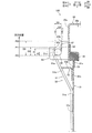
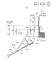
図8に示すように、本実施形態では、支持凹部61の深さ(距離D2)は、回動軸52の半径Rよりも大きくなるように構成されている。詳細には、支持凹部61の深さ(距離D2)は、回動軸52の直径Dよりも大きくなるように構成されている。また、本実施形態では、支持凹部61は、筐体30側とは反対側の上端部62aの高さ位置P1が、筐体30側の上端部62bの高さ位置P2よりも低くなるように構成されている。
As shown in FIG. 8, in the present embodiment, the depth (distance D2) of the
具体的には、支持凹部61は、X方向から見て、略U字状に形成された内側面62を有する。筐体30側とは反対側(Y1側)の内側面62と筐体30側(Y2側)の内側面62とのY方向における距離D3は、回動軸52の直径Dよりも僅かに大きく形成されている。これにより、通常時は、回動軸52が支持凹部61(の略U字状に形成された内側面62)に嵌り込んだ状態を容易に維持することが可能である。また、点検カバー31を筐体30から取り外す際には、回動軸52を、支持凹部61の内部において、内側面62に沿って上方に移動させて、支持凹部61から上方に取り外すことが可能となっている。
Specifically, the
そして、支持凹部61は、筐体30側とは反対側(Y1側)の内側面62の上端部62aが、(支持凹部61の下端の高さ位置P0からZ方向における距離D2だけ上方の)高さ位置P1となるように構成されている。また、支持凹部61は、筐体30側(Y2側)の内側面62の上端部62bが、(支持凹部61の下端の高さ位置P0からZ方向における距離D3だけ上方の)高さ位置P2となるように構成されている。なお、距離D2は、回動軸52の直径Dよりも大きい。また、距離D2は、距離D3よりも小さい。これにより、回動軸52を、支持凹部61の内部において、回動軸52の下端が支持凹部61の下端の高さ位置P0にある状態から、回動軸52の下端が支持凹部61の筐体30側とは反対側(Y1側)の内側面62の上端部62aの高さ位置P1よりも高くなる位置まで、(Z方向における距離D2だけ)、内側面62に沿って上方に移動させることによって、支持凹部61から上方に取り外すことが可能となっている。すなわち、距離D2は、支持凹部61の深さに相当する。
Then, in the
また、本実施形態では、支持凹部61の内側面62は、鉛直下方(Z2側)から鉛直上方(Z1側)に向かうにしたがって、筐体30側とは反対側(Y1側)から筐体30側(Y2側)に向かって傾斜するように形成されている。具体的には、支持凹部61は、筐体30側(Y2側)の内側面62および筐体30側とは反対側(Y1側)の内側面62が、筐体30側とは反対側(Y1側)から筐体30側(Y2側)に向かって、鉛直方向(Z方向)に対して角度θだけ傾斜している。角度θは、たとえば、7度以上10度以下である。
Further, in the present embodiment, the
次に、図5および図9〜図13を参照して、点検カバー31の筐体30に対する取付けおよび取外しについて説明する。
Next, attachment / detachment of the
図5に示すように、点検カバー31が筐体30に対して固定された状態では、カバー固定部材42の引掛かり部42bが、筐体30に対して引っ掛かっている。そして、図9に示すように、作業者は、カバー固定部材42のレバー部42aを回動させることによって、引掛かり部42bの筐体30に対する引っ掛かりを解除する。これにより、点検カバー31の筐体30に対する固定が解除された状態となる。
As shown in FIG. 5, when the
そして、図10に示すように、作業者は、カバー固定部材42に取り付けられた把持部材41を把持しながら、カバー固定部材42を筐体30側(Y2側)から筐体30側とは反対側(Y1側)に引っ張ることによって、点検カバー31を筐体30に対して回動させる。これにより、筐体30の開口部33が開いた状態となる。
Then, as shown in FIG. 10, the operator grips the
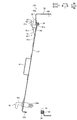
そして、図11に示すように、作業者は、図10の状態から、点検カバー31を筐体30に対してさらに回動させる。そして、図12に示すように、作業者は、回動軸52の下端が支持凹部61の下端の高さ位置P0にある状態(図11の状態)から、点検カバー31を上方に持ち上げることによって、回動軸52の下端が、支持凹部61の筐体30側とは反対側(Y1側)の内側面62の上端部62aの高さ位置P1よりも高くなるまで、点検カバー31を上方に持ち上げる。これにより、回動軸52の支持凹部61に対する嵌り込みが解除された状態となる。すなわち、電力変換装置100では、支持凹部61の下端の高さ位置P0から、支持凹部61の筐体30側とは反対側(Y1側)の内側面62の上端部62aの高さ位置P1までのZ方向における距離D2が、回動軸52を支持凹部61に嵌め込んだ際の回動軸52が支持凹部61に引っ掛っている鉛直方向(Z方向)における距離(掛け代)となっている。
Then, as shown in FIG. 11, the operator further rotates the
そして、図13に示すように、作業者は、点検カバー31を、回動軸52および点検カバー31の上側(Z1側)の端部31aが、回動軸支持部材60に対して、Z方向にオーバラップしない位置となるまで、筐体30側とは反対側(Y1側)に移動させる。これにより、点検カバー31を、筐体30から取り外すことができる。なお、点検カバー31の筐体30に対する取付けは、上記の点検カバー31の筐体30に対する取外しとは逆の手順によって行われる。
Then, as shown in FIG. 13, the operator puts the
(実施形態の効果)
本実施形態では、以下のような効果を得ることができる。
(Effect of embodiment)
In this embodiment, the following effects can be obtained.
本実施形態では、上記のように、点検カバー31側に、点検カバー31を筐体30に対して回動させるための回動軸52を設けるとともに、筐体30側に、回動軸52が嵌り込むように、かつ、回動軸52を回動可能に支持するように、下方(Z2側)に窪んだ支持凹部61を設ける。これにより、回動軸52が嵌り込むように下方に窪んだ支持凹部61の深さ(距離D2)が、掛け代(回動軸52を支持凹部61に嵌め込んだ際の回動軸52が支持凹部61に引っ掛っている鉛直方向における距離)となるので、支持凹部61の深さ(距離D2)を深くすることによって、点検カバー31側に設けられた回動軸52が筐体30側に設けられた支持凹部61から外れにくくなるように、掛け代を大きくすることができる。すなわち、フックに延長部分を設ける場合のように、筐体30側に向かって延びる部分が生じないので、点検カバー31の筐体に対する着脱の際に、筐体30に接触する部分が生じるのを抑制しながら、掛け代を大きくすることができる。その結果、筐体30に取り付けられた点検カバー31に筐体30の外側に向かって大きな圧力が加わった際に、点検カバー31が筐体30から外れて落下してしまうのを抑制することができる。
In the present embodiment, as described above, the
また、本実施形態では、上記のように、支持凹部61の深さ(距離D2)を、回動軸52の半径Rよりも大きくなるように構成する。これにより、掛け代(回動軸52を支持凹部61に嵌め込んだ際の回動軸が支持凹部61に引っ掛っている鉛直方向(Z方向)における距離)が回動軸52の半径Rよりも大きくなるので、支持凹部61の深さ(距離D2)が回動軸52の半径R以下の場合と比較して、回動軸52が支持凹部61から外れてしまうのを抑制することができる。
Further, in the present embodiment, as described above, the depth (distance D2) of the
また、本実施形態では、上記のように、支持凹部61の深さ(距離D2)を、回動軸52の直径Dよりも大きくなるように構成する。これにより、掛け代が回動軸52の直径Dよりも大きくなるので、支持凹部61の深さ(距離D2)が回動軸52の半径Rよりも大きく、かつ、直径D以下の場合と比較して、回動軸52が支持凹部61から外れてしまうのをより抑制することができる。
Further, in the present embodiment, as described above, the depth (distance D2) of the
また、本実施形態では、上記のように、支持凹部61を、回動軸52が延びる方向(X方向)に互いに離間するように一対設ける。そして、回動軸52を、一対の支持凹部61により支持されるように構成する。これにより、回動軸52を、回動軸52が延びる方向に互いに離間するように設けられた一対の支持凹部61により、安定して支持することができる。
Further, in the present embodiment, as described above, a pair of support recesses 61 are provided so as to be separated from each other in the direction in which the
また、本実施形態では、上記のように、支持凹部61を、筐体30側とは反対側(Y1側)の上端部62aの高さ位置P1が、筐体30側(Y2側)の上端部62bの高さ位置P2よりも低くなるように構成する。これにより、支持凹部61の筐体30側とは反対側(Y1側)の上端部62aの高さ位置P1が過度に高くなるのを抑制することができるので、回動軸52の支持凹部61に対する取り付けおよび取り外しのために、回動軸52(点検カバー31)を上方(Z1方向)に持ち上げる高さが過度に大きくなるのを抑制することができる。また、回動軸52を、筐体30側とは反対側(Y1側)の上端部62aの高さ位置P1の直上において、筐体30側とは反対側(Y1側)から筐体30側(Y2側)に向かって支持凹部61の筐体30側(Y2側)に接触するまで近付けて、下方(Z2方向)に移動させることによって、回動軸52を支持凹部61に嵌め込むことができるので、回動軸52を支持凹部61に対して容易に取り付けることができる。
Further, in the present embodiment, as described above, the height position P1 of the
また、本実施形態では、上記のように、支持凹部61の内側面62を、鉛直下方(Z2側)から鉛直上方(Z1側)に向かうにしたがって、筐体30側とは反対側(Y1側)から筐体30側(Y2側)に向かって傾斜するように形成する。これにより、回動軸52に対して、鉛直上方の力に加えて、筐体30の内側(Y2側)に向かう方向の力が作用しない限り、回動軸52が支持凹部61から外れないようにすることができる。なお、筐体30の内部30bの圧力が急激に上昇した際に点検カバー31に作用する圧力は、筐体30の外側(Y1側)に向かう方向の成分が主であり、筐体30の内側(Y2側)に向かう方向の成分を殆ど含まない。その結果、支持凹部61の内側面62が、鉛直下方から鉛直上方に向かうにしたがって、筐体30側とは反対側(Y1側)から筐体30側(Y2側)に向かって傾斜していない場合と比較して、点検カバー31に圧力が加わった際に回動軸52を支持凹部61から外れ難くすることができる。
Further, in the present embodiment, as described above, the
また、本実施形態では、上記のように、支持凹部61を、回動軸52の形状に対応するように、半円形状の下端部61aを有するように構成する。これにより、回動軸52が支持凹部61に嵌り込んだ状態で、回動軸52を容易に回動させることができるので、点検カバー31の筐体30に対する取付けおよび取外しの際に、点検カバー31を筐体30に対して容易に回動させることができる。
Further, in the present embodiment, as described above, the
また、本実施形態では、上記のように、電力変換装置100を、筐体30の点検カバー31が設けられる側の側面30aから突出するとともに、支持凹部61が設けられている回動軸支持部材60と、回動軸52と筐体30の内部30bを密閉するための点検カバー31とに接続する板状部材51と、を備えるように構成する。そして、板状部材51を、点検カバー31から回動軸52に向かうにしたがって、筐体30側(Y2側)から筐体30側とは反対側(Y1側)に向かって傾斜する部分(斜面部51b)を含むように形成する。これにより、回動軸52と点検カバー31とに接続する板状部材51が、筐体30側(Y2側)から筐体30側とは反対側(Y1側)に向かって傾斜する部分(斜面部51b)を含むので、板状部材51に接続された回動軸52の位置を、筐体30の点検カバー31が設けられる側の側面30aから筐体30側とは反対側(Y1側)に離間した位置に容易に配置することができる。その結果、筐体30の点検カバー31が設けられる側の側面30aから突出している回動軸支持部材60に設けられている支持凹部61に、板状部材51に接続された回動軸52を容易に嵌め込むことできる。
Further, in the present embodiment, as described above, the
また、本実施形態では、上記のように、電力変換装置100を、鉄道車両10に搭載される電力変換装置100として構成する。そして、開口部33を、筐体30の鉄道車両10の走行方向(X方向)と直交する方向(枕木方向、Y方向)における側面30aに形成する。また、点検カバー31を、筐体30の側面30aに形成された開口部33を覆うように、筐体30に対して着脱可能に取り付ける。これにより、鉄道車両10に設けられる電力変換装置100は、フィルタコンデンサとして(経年劣化に伴って破裂する場合がある)オイルコンデンサ22が使用されることが一般的なので、筐体30に取り付けられた点検カバー31に大きな圧力が加わった際に、点検カバー31が筐体30から外れて落下してしまうのを抑制することが可能な構成を効果的に適用することができる。また、開口部33が筐体30の鉄道車両10の走行方向と直交する方向における側面30aに形成されているので、メンテナンス(点検)時の作業性を向上させることができる。
Further, in the present embodiment, as described above, the
[変形例]
今回開示された実施形態は、全ての点で例示であり制限的なものではないと考えられるべきである。本発明の範囲は上記実施形態の説明ではなく特許請求の範囲によって示され、さらに特許請求の範囲と均等の意味および範囲内での全ての変更(変形例)が含まれる。
[Modification example]
The embodiments disclosed this time should be considered as exemplary in all respects and not restrictive. The scope of the present invention is shown not by the description of the above embodiment but by the scope of claims, and further includes all modifications (modifications) within the meaning and scope equivalent to the scope of claims.
たとえば、上記実施形態では、支持凹部61の深さ(距離D2)を、回動軸52の直径Dよりも大きくなるように構成した例を示したが、本発明はこれに限られない。本発明では、支持凹部の深さを、回動軸の直径よりも小さくなるように構成してもよい。その場合、支持凹部の深さを、少なくとも、回動軸の半径Rよりも大きくなるように構成することが好ましい。
For example, in the above embodiment, an example is shown in which the depth (distance D2) of the
また、上記実施形態では、支持凹部61を、筐体30側とは反対側(Y1側)の上端部62aの高さ位置P1が、筐体30側(Y2側)の上端部62bの高さ位置P2よりも低くなるように構成した例を示したが、本発明はこれに限られない。本発明では、支持凹部を、筐体側とは反対側の上端部の高さ位置が、筐体側の上端部の高さ位置よりも高くなるように構成してもよい。また、支持凹部を、筐体側とは反対側の上端部の高さ位置と、筐体側の上端部の高さ位置とが略等しくなるように構成してもよい。
Further, in the above embodiment, the height position P1 of the
また、上記実施形態では、支持凹部61の内側面62を、鉛直下方(Z2側)から鉛直上方(Z1側)に向かうにしたがって、筐体30側とは反対側(Y1側)から筐体30側(Y2側)に向かって傾斜するように構成した例を示したが、本発明はこれに限られない。本発明では、支持凹部の内側面を、鉛直方向に対して傾斜しないように構成してもよい。
Further, in the above embodiment, the
また、上記実施形態では、開口部33が、筐体30の鉄道車両10の走行方向と直交する方向(枕木方向、Y方向)における側面30aに形成された電力変換装置100の例を示したが、本発明はこれに限られない。本発明では、開口部が、筐体の鉄道車両の走行方向(X方向)における側面に形成された電力変換装置に適用してもよい。
Further, in the above embodiment, an example of the
また、上記実施形態では、板状部材51と回動軸52とが溶接等によって固定されたカバー回動用部材50を備えた例を示したが、本発明はこれに限られない。本発明では、板状部材と回動軸とが一体成型されたカバー回動用部材を備えるように構成してもよい。
Further, in the above embodiment, an example is shown in which the plate-shaped
また、上記実施形態では、レバー部42aを回動させるとレバー部42aの回動角度に応じた角度だけ引掛かり部42bが回動するカバー固定部材42により、点検カバー31を筐体30に対して固定するように構成した例を示したが、本発明はこれに限られない。本発明では、たとえば、点検カバーが筐体側のシール部材に当接するまで、点検カバーを筐体に対して回動させると、引掛かり部が筐体に引っ掛かることにより固定する方法等、他の方法により、点検カバーを筐体に対して固定するように構成してもよい。
Further, in the above embodiment, the
また、上記実施形態では、斜面部51bの筐体30側に補強板53を設けた例を示したが、本発明はこれに限られない。本発明では、斜面部の筐体側に補強板を設けないように構成してもよい。
Further, in the above embodiment, an example in which the reinforcing
また、上記実施形態では、密閉された筐体30内にオイルコンデンサ22が内蔵(収納)された電力変換装置100の例を示したが、本発明はこれに限られない。本発明を、密閉された筐体内に(ガスが発生することによって密閉された筐体の内部の圧力を上昇させる場合がある)ガスコンデンサが内蔵(収納)された電力変換装置に適用してもよい。また、本発明を、筐体に内蔵(収納)されている部品が脱落、破裂すること等によって、飛散した部品、または、その一部がカバー部材に衝突し、カバー部材に筐体の外側に向かって圧力が加わることが想定される電力変換装置に適用してもよい。
Further, in the above embodiment, an example of the
また、上記実施形態では、半導体スイッチング素子21を、MOSFETとして構成した例を示したが、本発明はこれに限られない。本発明では、半導体スイッチング素子を、IGBT(Insulated Gate Bipolar Transistor)として構成してもよい。
Further, in the above embodiment, an example in which the
また、上記実施形態では、電力変換装置100を、鉄道車両10に搭載される電力変換装置として構成した例を示したが、本発明はこれに限られない。すなわち、本発明の電力変換装置を、鉄道車両以外に搭載される(用いられる)電力変換装置に適用してもよい。
Further, in the above embodiment, an example in which the
10 鉄道車両
30 筐体
30a 筐体の(カバー部材が設けられる側の)面、筐体の側面
30b 筐体の内部
31 点検カバー(カバー部材)
33 開口部
51 板状部材(接続部材)
51b 斜面部(接続部材の筐体側から筐体側とは反対側に向かって傾斜する部分)
52 回動軸
60 回動軸支持部材(突出部材)
61 支持凹部
61a (支持凹部の)下端部
62 (支持凹部の)内側面
62a (支持凹部の)筐体側とは反対側の上端部
62b (支持凹部の)筐体側の上端部
100 電力変換装置
D (回動軸の)直径
P1 (支持凹部の筐体側とは反対側の上端部の)高さ位置
P2 (支持凹部の筐体側の上端部の)高さ位置
R (回動軸の)半径
10
33
51b Slope (a part of the connecting member that inclines from the housing side to the side opposite to the housing side)
52 Rotating
61
Claims (9)
前記開口部を覆うとともに、前記筐体に対して着脱可能に取り付けられるカバー部材と、
を備え、
前記カバー部材側には、前記カバー部材を前記筐体に対して回動させるための回動軸が設けられており、
前記筐体側には、前記回動軸が嵌り込むように、かつ、前記回動軸を回動可能に支持するように、下方に窪んだ支持凹部が設けられている、電力変換装置。 A housing with an opening and
A cover member that covers the opening and is detachably attached to the housing.
With
A rotation shaft for rotating the cover member with respect to the housing is provided on the cover member side.
A power conversion device provided with a downwardly recessed support recess on the housing side so that the rotation shaft is fitted and the rotation shaft is rotatably supported.
前記回動軸は、前記一対の支持凹部により支持されている、請求項1〜3のいずれか1項に記載の電力変換装置。 A pair of the support recesses are provided so as to be separated from each other in the direction in which the rotation shaft extends.
The power conversion device according to any one of claims 1 to 3, wherein the rotating shaft is supported by the pair of supporting recesses.
前記回動軸と前記筐体の内部を密閉するための前記カバー部材とに接続する接続部材と、
をさらに備え、
前記接続部材は、前記カバー部材から前記回動軸に向かうにしたがって、前記筐体側から前記筐体側とは反対側に向かって傾斜する部分を含むように形成されている、請求項1〜7のいずれか1項に記載の電力変換装置。 A projecting member that protrudes from the surface of the housing on which the cover member is provided and is provided with the support recess, and a projecting member.
A connecting member connected to the rotating shaft and the cover member for sealing the inside of the housing, and
With more
15. The power conversion device according to any one item.
前記開口部は、前記筐体の前記鉄道車両の走行方向または前記走行方向と直交する方向における側面に形成されており、
前記カバー部材は、前記筐体の側面に形成された前記開口部を覆うように、前記筐体に対して着脱可能に取り付けられている、請求項1〜8のいずれか1項に記載の電力変換装置。 A power converter mounted on a railroad vehicle
The opening is formed on a side surface of the housing in a traveling direction of the railway vehicle or a direction orthogonal to the traveling direction.
The electric power according to any one of claims 1 to 8, wherein the cover member is detachably attached to the housing so as to cover the opening formed on the side surface of the housing. Conversion device.
Priority Applications (1)
| Application Number | Priority Date | Filing Date | Title |
|---|---|---|---|
| JP2019154529A JP7388048B2 (en) | 2019-08-27 | 2019-08-27 | power converter |
Applications Claiming Priority (1)
| Application Number | Priority Date | Filing Date | Title |
|---|---|---|---|
| JP2019154529A JP7388048B2 (en) | 2019-08-27 | 2019-08-27 | power converter |
Publications (2)
| Publication Number | Publication Date |
|---|---|
| JP2021034603A true JP2021034603A (en) | 2021-03-01 |
| JP7388048B2 JP7388048B2 (en) | 2023-11-29 |
Family
ID=74676059
Family Applications (1)
| Application Number | Title | Priority Date | Filing Date |
|---|---|---|---|
| JP2019154529A Active JP7388048B2 (en) | 2019-08-27 | 2019-08-27 | power converter |
Country Status (1)
| Country | Link |
|---|---|
| JP (1) | JP7388048B2 (en) |
Citations (10)
| Publication number | Priority date | Publication date | Assignee | Title |
|---|---|---|---|---|
| JPH0630385U (en) * | 1992-04-28 | 1994-04-19 | 日本無線株式会社 | Hinge mechanism of waterproof housing |
| JPH06225432A (en) * | 1993-01-26 | 1994-08-12 | Yazaki Corp | Cover attaching structure |
| JPH0713270Y2 (en) * | 1990-04-04 | 1995-03-29 | 富士通株式会社 | Cover opener for desktop equipment |
| JPH0930413A (en) * | 1995-07-20 | 1997-02-04 | Kawasaki Heavy Ind Ltd | Vehicle side cover plate mounting and fixing device |
| JPH0930412A (en) * | 1995-07-19 | 1997-02-04 | Nippon Sharyo Seizo Kaisha Ltd | Cover body opening and closing device for rail-way rolling stock |
| JPH09124056A (en) * | 1995-10-30 | 1997-05-13 | Oki Electric Ind Co Ltd | Opening/closing cover mounting structure |
| JP2008002111A (en) * | 2006-06-21 | 2008-01-10 | Matsushita Electric Ind Co Ltd | Lid hinge mechanism |
| JP2009119938A (en) * | 2007-11-13 | 2009-06-04 | Toyo Electric Mfg Co Ltd | Railway vehicle control system |
| JP2013172123A (en) * | 2012-02-23 | 2013-09-02 | Nitto Kogyo Co Ltd | Electric apparatus housing box |
| JP2016127102A (en) * | 2014-12-26 | 2016-07-11 | 株式会社東芝 | Electronic equipment housing |
-
2019
- 2019-08-27 JP JP2019154529A patent/JP7388048B2/en active Active
Patent Citations (10)
| Publication number | Priority date | Publication date | Assignee | Title |
|---|---|---|---|---|
| JPH0713270Y2 (en) * | 1990-04-04 | 1995-03-29 | 富士通株式会社 | Cover opener for desktop equipment |
| JPH0630385U (en) * | 1992-04-28 | 1994-04-19 | 日本無線株式会社 | Hinge mechanism of waterproof housing |
| JPH06225432A (en) * | 1993-01-26 | 1994-08-12 | Yazaki Corp | Cover attaching structure |
| JPH0930412A (en) * | 1995-07-19 | 1997-02-04 | Nippon Sharyo Seizo Kaisha Ltd | Cover body opening and closing device for rail-way rolling stock |
| JPH0930413A (en) * | 1995-07-20 | 1997-02-04 | Kawasaki Heavy Ind Ltd | Vehicle side cover plate mounting and fixing device |
| JPH09124056A (en) * | 1995-10-30 | 1997-05-13 | Oki Electric Ind Co Ltd | Opening/closing cover mounting structure |
| JP2008002111A (en) * | 2006-06-21 | 2008-01-10 | Matsushita Electric Ind Co Ltd | Lid hinge mechanism |
| JP2009119938A (en) * | 2007-11-13 | 2009-06-04 | Toyo Electric Mfg Co Ltd | Railway vehicle control system |
| JP2013172123A (en) * | 2012-02-23 | 2013-09-02 | Nitto Kogyo Co Ltd | Electric apparatus housing box |
| JP2016127102A (en) * | 2014-12-26 | 2016-07-11 | 株式会社東芝 | Electronic equipment housing |
Also Published As
| Publication number | Publication date |
|---|---|
| JP7388048B2 (en) | 2023-11-29 |
Similar Documents
| Publication | Publication Date | Title |
|---|---|---|
| US8579128B2 (en) | Gripper device for transport vehicle, transport vehicle and overhead hoist transport vehicle | |
| US11377324B2 (en) | Jump elevator and jumping method | |
| JP6364996B2 (en) | lift device | |
| JP5148238B2 (en) | High-speed railway vehicle power converter | |
| JPWO2012124101A1 (en) | Electronic equipment casing | |
| JP2021034603A (en) | Power conversion device | |
| US10075089B2 (en) | Power conversion device | |
| CN116897502A (en) | Vehicle drive device | |
| JP5439216B2 (en) | Power supply | |
| JP2007131128A (en) | Railway vehicle power converter | |
| KR102238042B1 (en) | Case structure of high voltage battery | |
| JP2015116082A (en) | Power conversion device for vehicle and railway vehicle | |
| CN219021026U (en) | Mobile base station | |
| JP7662298B2 (en) | Power converter enclosure | |
| CN214375437U (en) | Optical cable distributing box convenient to maintain | |
| JP2013052715A (en) | Railroad vehicle | |
| JP2006349087A (en) | Seal structure of cable insertion part | |
| CN115722660A (en) | Fixed-point ramp driving type hot-metal bottle capping and uncapping device and method | |
| CN212752969U (en) | IGBT circuit protection structure | |
| JP6809388B2 (en) | Controller box in explosion-proof vehicle | |
| JP5515908B2 (en) | Power supply device and vehicle equipped with the same | |
| CN219571386U (en) | Supporting device of industrial automatic control instrument | |
| JPH0515586B2 (en) | ||
| JP2021057536A (en) | Electric device case | |
| WO2023238223A1 (en) | Vehicular electric power converting device |
Legal Events
| Date | Code | Title | Description |
|---|---|---|---|
| A621 | Written request for application examination |
Free format text: JAPANESE INTERMEDIATE CODE: A621 Effective date: 20220713 |
|
| A977 | Report on retrieval |
Free format text: JAPANESE INTERMEDIATE CODE: A971007 Effective date: 20230426 |
|
| A131 | Notification of reasons for refusal |
Free format text: JAPANESE INTERMEDIATE CODE: A131 Effective date: 20230530 |
|
| A521 | Request for written amendment filed |
Free format text: JAPANESE INTERMEDIATE CODE: A523 Effective date: 20230706 |
|
| TRDD | Decision of grant or rejection written | ||
| A01 | Written decision to grant a patent or to grant a registration (utility model) |
Free format text: JAPANESE INTERMEDIATE CODE: A01 Effective date: 20231017 |
|
| A61 | First payment of annual fees (during grant procedure) |
Free format text: JAPANESE INTERMEDIATE CODE: A61 Effective date: 20231030 |
|
| R150 | Certificate of patent or registration of utility model |
Ref document number: 7388048 Country of ref document: JP Free format text: JAPANESE INTERMEDIATE CODE: R150 |