JP2021055893A - Hot water mat for floor heating - Google Patents
Hot water mat for floor heating Download PDFInfo
- Publication number
- JP2021055893A JP2021055893A JP2019178408A JP2019178408A JP2021055893A JP 2021055893 A JP2021055893 A JP 2021055893A JP 2019178408 A JP2019178408 A JP 2019178408A JP 2019178408 A JP2019178408 A JP 2019178408A JP 2021055893 A JP2021055893 A JP 2021055893A
- Authority
- JP
- Japan
- Prior art keywords
- hot water
- floor heating
- mat
- header
- water mat
- Prior art date
- Legal status (The legal status is an assumption and is not a legal conclusion. Google has not performed a legal analysis and makes no representation as to the accuracy of the status listed.)
- Pending
Links
Images


Classifications
-
- F—MECHANICAL ENGINEERING; LIGHTING; HEATING; WEAPONS; BLASTING
- F24—HEATING; RANGES; VENTILATING
- F24D—DOMESTIC- OR SPACE-HEATING SYSTEMS, e.g. CENTRAL HEATING SYSTEMS; DOMESTIC HOT-WATER SUPPLY SYSTEMS; ELEMENTS OR COMPONENTS THEREFOR
- F24D15/00—Other domestic- or space-heating systems
- F24D15/02—Other domestic- or space-heating systems consisting of self-contained heating units, e.g. storage heaters
-
- F—MECHANICAL ENGINEERING; LIGHTING; HEATING; WEAPONS; BLASTING
- F24—HEATING; RANGES; VENTILATING
- F24D—DOMESTIC- OR SPACE-HEATING SYSTEMS, e.g. CENTRAL HEATING SYSTEMS; DOMESTIC HOT-WATER SUPPLY SYSTEMS; ELEMENTS OR COMPONENTS THEREFOR
- F24D19/00—Details
- F24D19/02—Arrangement of mountings or supports for radiators
Landscapes
- Engineering & Computer Science (AREA)
- Physics & Mathematics (AREA)
- Thermal Sciences (AREA)
- Chemical & Material Sciences (AREA)
- Combustion & Propulsion (AREA)
- Mechanical Engineering (AREA)
- General Engineering & Computer Science (AREA)
- Steam Or Hot-Water Central Heating Systems (AREA)
- Floor Finish (AREA)
Abstract
Description
本発明は、マット本体に配管した放熱用の温水パイプ内に温水を通し、この温水の輻射熱を用いて暖房を行う際に用いられる床暖房用温水マットに関する。 The present invention relates to a hot water mat for floor heating, which is used when hot water is passed through a hot water pipe for heat dissipation piped to a mat body and heating is performed using the radiant heat of the hot water.
従来の床暖房用温水マットは、公知文献1・2に開示するようにマット本体の一部に温水送り口と戻り口を形成した温水ヘッダーを取り付け、このヘッダー間に温水パイプ(放熱パイプ)を1本往復で蛇行配管した構成である。
なお、このマットには、表面に均熱シートを張設したタイプと、公知文献3に開示されているように小根太(床材支持材)をマットに挿入したタイプがある。
In the conventional hot water mat for floor heating, as disclosed in
There are two types of this mat, one is a type in which a heat equalizing sheet is stretched on the surface, and the other is a type in which a small joist (floor material support material) is inserted into the mat as disclosed in
このような床暖房用温水マットにおいて、温水パイプからの放熱量を増大したい場合には、温水の温度を通常の60℃から70℃〜90℃に変更する必要があるが、この温水の温度の変更・調整は熱源機側で行うため熱源機の取り替え等が必要となり、実用的には非常に困難なものとなっている。 In such a hot water mat for floor heating, if it is desired to increase the amount of heat radiated from the hot water pipe, it is necessary to change the temperature of the hot water from the usual 60 ° C to 70 ° C to 90 ° C. Since changes and adjustments are made on the heat source machine side, it is necessary to replace the heat source machine, which makes it extremely difficult in practical use.
本発明は、このような現状に鑑み、温水マット側で温水パイプからの放熱量を増大できるようにすると共に、圧損を減じ、施工性を向上させた床暖房用温水マットを提供することを目的とする。 In view of such a current situation, it is an object of the present invention to provide a hot water mat for floor heating which can increase the amount of heat radiated from the hot water pipe on the hot water mat side, reduce pressure loss, and improve workability. And.
上記目的を達成するため、請求項1に記載の発明は、床暖房用温水マットにおいて、平面視四角形の温水マット本体の一部に3又は4口の入水ヘッダーを設けると共に、前記温水マット本体の他部に3又は4口の出水ヘッダーを設けたこと、前記入水ヘッダー及び出水ヘッダー用に3又は4本の温水パイプを並列状態で直列に配管したこと、を特徴とするものである。
In order to achieve the above object, the invention according to
請求項2に記載の発明は、床暖房用温水マットにおいて、請求項1に係る床暖房用温水マット本体を用いて床暖房面積を拡大する場合には、前記床暖房用温水マットの出水ヘッダーと別体の床暖房用温水マットの入水ヘッダーを対向させて敷設すると共に、一方の前記出水ヘッダーと他方の前記入水ヘッダーを連絡管で連通させたこと、を特徴とするものである。 According to the second aspect of the present invention, when the floor heating area is expanded by using the floor heating hot water mat main body according to the first aspect of the floor heating hot water mat, the water discharge header of the floor heating hot water mat is used. It is characterized in that the water inlet headers of separate hot water mats for floor heating are laid facing each other, and the water outlet header on one side and the water inlet header on the other side are communicated with each other by a connecting pipe.
請求項3に記載の発明は、請求項1又は請求項2に係る床暖房用温水マットおいて、各3又は4本の温水パイプは、すべて直列に配管されていること、を特徴とするものである。
The invention according to
請求項4に記載の発明は、請求項1又は請求項2に係る床暖房用温水マットには小根太が挿入されていること、を特徴とするものである。
The invention according to
本発明に係る床暖房用温水マットの施工法は、現在実用化されている方法と同一である。
但し、従来の床暖房用温水マット内の温水パイプは、1又は2本の温水パイプを往復状態・並列状態でマット内に蛇行配管されているため、前記公知文献1・2に比較して圧損が大きく、放熱量を増大させることは不可能である。
The method of constructing the hot water mat for floor heating according to the present invention is the same as the method currently in practical use.
However, since the hot water pipe in the conventional hot water mat for floor heating has one or two hot water pipes meanderingly piped in the mat in a reciprocating state and a parallel state, the pressure loss is compared with the above-mentioned
一方、本発明は、温水パイプを3又は4本並列で配管したことにより、その分圧損は減少し、高熱量の放出が可能となり熱源機の負荷も軽減される。 On the other hand, in the present invention, by piping three or four hot water pipes in parallel, the pressure loss thereof is reduced, a high amount of heat can be released, and the load on the heat source machine is also reduced.
また、本発明によると、熱源機側ではなく温水マット側で放熱量を増大させることが可能となる。 Further, according to the present invention, it is possible to increase the amount of heat radiation not on the heat source machine side but on the hot water mat side.
以下、図1〜10を用いて本発明の実施例を詳細に説明する。 Hereinafter, examples of the present invention will be described in detail with reference to FIGS. 1 to 10.
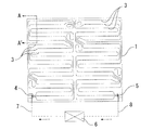
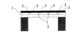
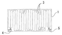
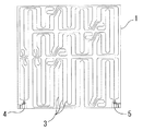
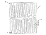
図1、2において、符号の1は平面視四角形の温水マット本体であり、2は温水マット本体1の上面に形成された配管溝、3は配管溝2内に配管された温水パイプ(放熱パイプ)、4は入水ヘッダー、5は出水ヘッダー、6は熱源機、7は温水往き導管、8は温水還り導管である。
In FIGS. 1 and 2,
図1に示すように、熱源機6内の温水は、温水往き導管7を介して入水ヘッダー4から温水マット本体1内に入り、3列平行で温水マット本体1内を一巡した後、出水ヘッダー5から温水還り導管8を介して熱源機6に戻る。
As shown in FIG. 1, the hot water in the
入水ヘッダー4の入水方向及び出水ヘッダー5の出水方向は各図に示す方向に限定されるものではなく、それらは平面視で上下左右方向や床下方向とすることができるため、例えば導管7、8を床下に配管する等、様々な配管方法が選択できる。
The water entry direction of the
また、入水ヘッダー4は温水還り導管8と結ぶことにより出水ヘッダーとして、出水ヘッダー5は温水往き導管7と結ぶことにより入水ヘッダーとしても使用することができ、部屋の形状やレイアウトに合わせて柔軟な対応が可能となる。
Further, the
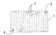
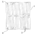
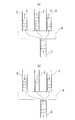
図7は温水マット本体1内に小根太9を挿入した例、図8は温水パイプ3を4本並行・直列で配管した実施例であり、図9は温水の流れを示す3口の入水ヘッダー4及び出水ヘッダーの説明図、図10は温水の流れを示す4口の入水ヘッダー4及び出水ヘッダーの説明図である。
FIG. 7 shows an example in which a
なお、マット本体1の表面には放熱シートが張設されているが、このシートは図中においてその表示は省略されている。
A heat radiating sheet is stretched on the surface of the
1 マット本体
2 配管溝
3 温水パイプ(放熱パイプ)
4 入水ヘッダー
5 出水ヘッダー
6 熱源機
7 温水往き導管
8 温水還り導管
9 小根太
1
4
Claims (4)
前記入水ヘッダー及び出水ヘッダー用に3又は4本の温水パイプを並列状態で直列に配管したこと、を特徴とする床暖房用温水マット。 A part of the hot water mat body having a square view in a plan view is provided with 3 or 4 water inlet headers, and 3 or 4 water outlet headers are provided in the other part of the hot water mat body.
A hot water mat for floor heating, characterized in that three or four hot water pipes are connected in series in parallel for the water inlet header and the water outlet header.
A hot water mat for floor heating according to claim 1 or 2, wherein a small joist is inserted in the hot water mat for floor heating.
Priority Applications (2)
| Application Number | Priority Date | Filing Date | Title |
|---|---|---|---|
| JP2019178408A JP2021055893A (en) | 2019-09-30 | 2019-09-30 | Hot water mat for floor heating |
| CN201911270126.XA CN112577095A (en) | 2019-09-30 | 2019-12-12 | Hot water pad for heating floor |
Applications Claiming Priority (1)
| Application Number | Priority Date | Filing Date | Title |
|---|---|---|---|
| JP2019178408A JP2021055893A (en) | 2019-09-30 | 2019-09-30 | Hot water mat for floor heating |
Publications (1)
| Publication Number | Publication Date |
|---|---|
| JP2021055893A true JP2021055893A (en) | 2021-04-08 |
Family
ID=75117176
Family Applications (1)
| Application Number | Title | Priority Date | Filing Date |
|---|---|---|---|
| JP2019178408A Pending JP2021055893A (en) | 2019-09-30 | 2019-09-30 | Hot water mat for floor heating |
Country Status (2)
| Country | Link |
|---|---|
| JP (1) | JP2021055893A (en) |
| CN (1) | CN112577095A (en) |
Citations (1)
| Publication number | Priority date | Publication date | Assignee | Title |
|---|---|---|---|---|
| JP2016033435A (en) * | 2014-07-31 | 2016-03-10 | 住商メタレックス株式会社 | Floor heating system |
Family Cites Families (9)
| Publication number | Priority date | Publication date | Assignee | Title |
|---|---|---|---|---|
| DE2742402A1 (en) * | 1977-09-21 | 1979-03-29 | Hoechst Ag | UNDERFLOOR HEATING |
| JP2003343858A (en) * | 2002-05-23 | 2003-12-03 | Noritz Corp | Floor heating system |
| JP4771781B2 (en) * | 2005-10-17 | 2011-09-14 | 株式会社ガスター | Heating system |
| CN101046309B (en) * | 2006-03-30 | 2011-08-10 | 住商美达力士株式会社 | Hot water pad for folded floor radiator |
| JP5281303B2 (en) * | 2008-03-14 | 2013-09-04 | 大阪瓦斯株式会社 | Heating system |
| CN101240928A (en) * | 2008-03-19 | 2008-08-13 | 何政林 | Precasting type repairable low-temperature radiation cool-supply and heating system |
| JP6479300B2 (en) * | 2012-10-31 | 2019-03-06 | 住商メタレックス株式会社 | Hot water mat for floor heating |
| CN103486880A (en) * | 2013-09-18 | 2014-01-01 | 张伟 | Header thermal fluid flow passage tube cavity water-storage and pressure-bearing heat exchanger and manufacture process thereof |
| CN108679684A (en) * | 2018-05-30 | 2018-10-19 | 崔党营 | A kind of installing and connecting apparatus of multi-functional floor heating pipe |
-
2019
- 2019-09-30 JP JP2019178408A patent/JP2021055893A/en active Pending
- 2019-12-12 CN CN201911270126.XA patent/CN112577095A/en active Pending
Patent Citations (1)
| Publication number | Priority date | Publication date | Assignee | Title |
|---|---|---|---|---|
| JP2016033435A (en) * | 2014-07-31 | 2016-03-10 | 住商メタレックス株式会社 | Floor heating system |
Also Published As
| Publication number | Publication date |
|---|---|
| CN112577095A (en) | 2021-03-30 |
Similar Documents
| Publication | Publication Date | Title |
|---|---|---|
| US20170089643A1 (en) | Heat Exchanger | |
| JP5817775B2 (en) | Chiller device | |
| MY196508A (en) | Energy Distributing System | |
| US20170184352A1 (en) | Radiator having a reverse flow manifold | |
| JP2017180984A5 (en) | ||
| JP2019519745A (en) | Combined heating and cooling system | |
| CN206724759U (en) | A kind of Heat Exchangers | |
| JP2013113488A (en) | Heat exchanger attached type hot water storage device | |
| JP5239962B2 (en) | Thermal storage device and hot water heater provided with the same | |
| JP2021055893A (en) | Hot water mat for floor heating | |
| KR101878247B1 (en) | Heat exchanger for individual household and installation method thereof | |
| JP7702300B2 (en) | Heat storage type hot water supply device and heat pump type hot water supply device | |
| JP2011196627A (en) | Header used in hot water mat for hot water-type floor heating | |
| JP7067028B2 (en) | Hot water heating device | |
| JP2022168278A (en) | Heat exchanger | |
| CN210688727U (en) | Heating water heater | |
| JP2008107080A (en) | Floor heating system | |
| KR101239895B1 (en) | Fixing bracket for fixing heat exchanger | |
| CN106288923A (en) | A kind of bilateral type heat exchanger hydroecium | |
| JP2009180467A (en) | Heat exchanger | |
| JP6449583B2 (en) | Non-room floor heating system | |
| EP3084316B1 (en) | Heat exchanger apparatus | |
| JP5268056B2 (en) | Hot water mat for floor heating with small joists | |
| JP5218175B2 (en) | Thermal storage device and hot water heater provided with the same | |
| CN223649459U (en) | Radiator for air conditioning system |
Legal Events
| Date | Code | Title | Description |
|---|---|---|---|
| A711 | Notification of change in applicant |
Free format text: JAPANESE INTERMEDIATE CODE: A712 Effective date: 20200624 |
|
| A521 | Request for written amendment filed |
Free format text: JAPANESE INTERMEDIATE CODE: A523 Effective date: 20200827 |
|
| A621 | Written request for application examination |
Free format text: JAPANESE INTERMEDIATE CODE: A621 Effective date: 20210602 |
|
| A977 | Report on retrieval |
Free format text: JAPANESE INTERMEDIATE CODE: A971007 Effective date: 20220323 |
|
| A131 | Notification of reasons for refusal |
Free format text: JAPANESE INTERMEDIATE CODE: A131 Effective date: 20220331 |
|
| A601 | Written request for extension of time |
Free format text: JAPANESE INTERMEDIATE CODE: A601 Effective date: 20220518 |
|
| A521 | Request for written amendment filed |
Free format text: JAPANESE INTERMEDIATE CODE: A523 Effective date: 20220727 |
|
| A02 | Decision of refusal |
Free format text: JAPANESE INTERMEDIATE CODE: A02 Effective date: 20220901 |