JP2021069243A - 配線部材の固定構造及び発熱層付配線部材 - Google Patents
配線部材の固定構造及び発熱層付配線部材 Download PDFInfo
- Publication number
- JP2021069243A JP2021069243A JP2019194980A JP2019194980A JP2021069243A JP 2021069243 A JP2021069243 A JP 2021069243A JP 2019194980 A JP2019194980 A JP 2019194980A JP 2019194980 A JP2019194980 A JP 2019194980A JP 2021069243 A JP2021069243 A JP 2021069243A
- Authority
- JP
- Japan
- Prior art keywords
- wiring member
- layer
- heat generating
- adherend
- generating layer
- Prior art date
- Legal status (The legal status is an assumption and is not a legal conclusion. Google has not performed a legal analysis and makes no representation as to the accuracy of the status listed.)
- Granted
Links
- 238000010438 heat treatment Methods 0.000 claims abstract description 47
- 230000005540 biological transmission Effects 0.000 claims abstract description 20
- 230000006698 induction Effects 0.000 claims description 15
- 238000000034 method Methods 0.000 abstract description 5
- 238000010586 diagram Methods 0.000 abstract 1
- 239000010410 layer Substances 0.000 description 223
- 239000000853 adhesive Substances 0.000 description 7
- 230000001070 adhesive effect Effects 0.000 description 7
- 239000002390 adhesive tape Substances 0.000 description 7
- 239000004020 conductor Substances 0.000 description 4
- 230000005611 electricity Effects 0.000 description 3
- 230000001939 inductive effect Effects 0.000 description 3
- 230000004048 modification Effects 0.000 description 3
- 238000012986 modification Methods 0.000 description 3
- 230000000149 penetrating effect Effects 0.000 description 3
- 239000011888 foil Substances 0.000 description 2
- 239000000463 material Substances 0.000 description 2
- 230000001012 protector Effects 0.000 description 2
- 239000013585 weight reducing agent Substances 0.000 description 2
- RYGMFSIKBFXOCR-UHFFFAOYSA-N Copper Chemical compound [Cu] RYGMFSIKBFXOCR-UHFFFAOYSA-N 0.000 description 1
- 239000004831 Hot glue Substances 0.000 description 1
- 229910052782 aluminium Inorganic materials 0.000 description 1
- XAGFODPZIPBFFR-UHFFFAOYSA-N aluminium Chemical compound [Al] XAGFODPZIPBFFR-UHFFFAOYSA-N 0.000 description 1
- 239000011247 coating layer Substances 0.000 description 1
- 239000011889 copper foil Substances 0.000 description 1
- 210000003298 dental enamel Anatomy 0.000 description 1
- 239000000428 dust Substances 0.000 description 1
- 230000000694 effects Effects 0.000 description 1
- 230000005674 electromagnetic induction Effects 0.000 description 1
- 230000001747 exhibiting effect Effects 0.000 description 1
- 229910052751 metal Inorganic materials 0.000 description 1
- 239000002184 metal Substances 0.000 description 1
- 229910001120 nichrome Inorganic materials 0.000 description 1
- 239000013307 optical fiber Substances 0.000 description 1
- 229920005989 resin Polymers 0.000 description 1
- 239000011347 resin Substances 0.000 description 1
- 229920005992 thermoplastic resin Polymers 0.000 description 1
- 229920001187 thermosetting polymer Polymers 0.000 description 1
- 238000004804 winding Methods 0.000 description 1
Images


Classifications
-
- H—ELECTRICITY
- H01—ELECTRIC ELEMENTS
- H01B—CABLES; CONDUCTORS; INSULATORS; SELECTION OF MATERIALS FOR THEIR CONDUCTIVE, INSULATING OR DIELECTRIC PROPERTIES
- H01B7/00—Insulated conductors or cables characterised by their form
- H01B7/40—Insulated conductors or cables characterised by their form with arrangements for facilitating mounting or securing
-
- B—PERFORMING OPERATIONS; TRANSPORTING
- B60—VEHICLES IN GENERAL
- B60R—VEHICLES, VEHICLE FITTINGS, OR VEHICLE PARTS, NOT OTHERWISE PROVIDED FOR
- B60R16/00—Electric or fluid circuits specially adapted for vehicles and not otherwise provided for; Arrangement of elements of electric or fluid circuits specially adapted for vehicles and not otherwise provided for
- B60R16/02—Electric or fluid circuits specially adapted for vehicles and not otherwise provided for; Arrangement of elements of electric or fluid circuits specially adapted for vehicles and not otherwise provided for electric constitutive elements
- B60R16/0207—Wire harnesses
- B60R16/0215—Protecting, fastening and routing means therefor
-
- C—CHEMISTRY; METALLURGY
- C09—DYES; PAINTS; POLISHES; NATURAL RESINS; ADHESIVES; COMPOSITIONS NOT OTHERWISE PROVIDED FOR; APPLICATIONS OF MATERIALS NOT OTHERWISE PROVIDED FOR
- C09J—ADHESIVES; NON-MECHANICAL ASPECTS OF ADHESIVE PROCESSES IN GENERAL; ADHESIVE PROCESSES NOT PROVIDED FOR ELSEWHERE; USE OF MATERIALS AS ADHESIVES
- C09J7/00—Adhesives in the form of films or foils
- C09J7/30—Adhesives in the form of films or foils characterised by the adhesive composition
- C09J7/35—Heat-activated
-
- H—ELECTRICITY
- H02—GENERATION; CONVERSION OR DISTRIBUTION OF ELECTRIC POWER
- H02G—INSTALLATION OF ELECTRIC CABLES OR LINES, OR OF COMBINED OPTICAL AND ELECTRIC CABLES OR LINES
- H02G3/00—Installations of electric cables or lines or protective tubing therefor in or on buildings, equivalent structures or vehicles
- H02G3/30—Installations of cables or lines on walls, floors or ceilings
- H02G3/305—Mounting by adhesive material
-
- H—ELECTRICITY
- H05—ELECTRIC TECHNIQUES NOT OTHERWISE PROVIDED FOR
- H05B—ELECTRIC HEATING; ELECTRIC LIGHT SOURCES NOT OTHERWISE PROVIDED FOR; CIRCUIT ARRANGEMENTS FOR ELECTRIC LIGHT SOURCES, IN GENERAL
- H05B6/00—Heating by electric, magnetic or electromagnetic fields
- H05B6/02—Induction heating
- H05B6/10—Induction heating apparatus, other than furnaces, for specific applications
Landscapes
- Engineering & Computer Science (AREA)
- Architecture (AREA)
- Civil Engineering (AREA)
- Structural Engineering (AREA)
- Mechanical Engineering (AREA)
- Physics & Mathematics (AREA)
- Electromagnetism (AREA)
- Organic Chemistry (AREA)
- Chemical & Material Sciences (AREA)
- Laminated Bodies (AREA)
- General Induction Heating (AREA)
- Adhesive Tapes (AREA)
- Insulated Conductors (AREA)
- Installation Of Indoor Wiring (AREA)
- Surface Heating Bodies (AREA)
Abstract
Description
最初に本開示の実施態様を列記して説明する。
本開示の配線部材の固定構造の具体例を、以下に図面を参照しつつ説明する。なお、本発明はこれらの例示に限定されるものではなく、特許請求の範囲によって示され、特許請求の範囲と均等の意味及び範囲内でのすべての変更が含まれることが意図される。
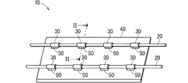
以下、実施形態1にかかる配線部材の固定構造について説明する。図1は実施形態1にかかる配線部材の固定構造10を示す斜視図である。図2は図1におけるII−II線に沿った断面図である。
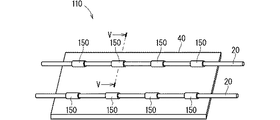
実施形態2にかかる配線部材の固定構造について説明する。図4は実施形態2にかかる配線部材の固定構造110を示す斜視図である。図5は図4におけるV−V線に沿った断面図である。なお、本実施形態の説明において、これまで説明したものと同様構成要素については同一符号を付してその説明を省略する。
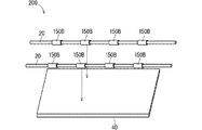
各実施形態において、少なくとも発熱層30と被着体40との間に接合層50、150が設けられていたが、このことは必須の構成ではない。発熱層30と被着体40との間に接合層50、150が設けられずに発熱層30と配線部材20との間に接合層152が設けられるように構成されていてもよい。
20 配線部材
22 線状伝送部材
30 発熱層
40 被着体
50、50B 接合層(被着体側接合層)
150、150B 接合層(被着体側接合層)
152 接合層(配線部材側接合層)
100、200 発熱層付配線部材
Claims (6)
- 少なくとも1本の線状伝送部材を含む配線部材と、
前記配線部材の周囲を囲むように設けられた発熱層と、
前記配線部材が固定されている被着体と、
前記発熱層と前記被着体との間及び前記発熱層と前記配線部材との間の少なくとも一方に設けられた接合層と、
を備え、
前記発熱層は誘導加熱によって発熱可能な層であり、
前記接合層は誘導加熱時に前記発熱層から伝わる熱によって接合性を呈するようになる層であり、前記被着体及び前記配線部材の少なくとも一方と前記発熱層とに接合している、配線部材の固定構造。 - 請求項1に記載の配線部材の固定構造であって、
前記接合層は、前記発熱層と前記被着体との間に設けられて前記発熱層及び前記被着体に接合している被着体側接合層を含む、配線部材の固定構造。 - 請求項2に記載の配線部材の固定構造であって、
前記被着体側接合層は、前記発熱層の周囲を囲むように設けられている、配線部材の固定構造。 - 請求項1から請求項3のいずれか1項に記載の配線部材の固定構造であって、
前記接合層は、前記発熱層と前記配線部材との間に設けられて前記発熱層及び前記配線部材に接合している配線部材側接合層を含む、配線部材の固定構造。 - 請求項1から請求項4のいずれか1項に記載の配線部材の固定構造であって、
前記発熱層は前記配線部材の長手方向に沿って部分的に設けられている、配線部材の固定構造。 - 少なくとも1本の線状伝送部材を含む配線部材と、
前記配線部材の周囲を囲むように設けられた発熱層と、
を備え、
前記発熱層は誘導加熱によって発熱可能な層である、発熱層付配線部材。
Priority Applications (4)
| Application Number | Priority Date | Filing Date | Title |
|---|---|---|---|
| JP2019194980A JP7395959B2 (ja) | 2019-10-28 | 2019-10-28 | 配線部材の固定構造 |
| PCT/JP2020/031604 WO2021084861A1 (ja) | 2019-10-28 | 2020-08-21 | 配線部材の固定構造及び発熱層付配線部材 |
| US17/768,350 US12009124B2 (en) | 2019-10-28 | 2020-08-21 | Fixing structure of wiring member, and wiring member with heat generation layer |
| CN202080074099.3A CN114599554A (zh) | 2019-10-28 | 2020-08-21 | 配线构件的固定结构以及带发热层的配线构件 |
Applications Claiming Priority (1)
| Application Number | Priority Date | Filing Date | Title |
|---|---|---|---|
| JP2019194980A JP7395959B2 (ja) | 2019-10-28 | 2019-10-28 | 配線部材の固定構造 |
Publications (2)
| Publication Number | Publication Date |
|---|---|
| JP2021069243A true JP2021069243A (ja) | 2021-04-30 |
| JP7395959B2 JP7395959B2 (ja) | 2023-12-12 |
Family
ID=75637621
Family Applications (1)
| Application Number | Title | Priority Date | Filing Date |
|---|---|---|---|
| JP2019194980A Active JP7395959B2 (ja) | 2019-10-28 | 2019-10-28 | 配線部材の固定構造 |
Country Status (4)
| Country | Link |
|---|---|
| US (1) | US12009124B2 (ja) |
| JP (1) | JP7395959B2 (ja) |
| CN (1) | CN114599554A (ja) |
| WO (1) | WO2021084861A1 (ja) |
Citations (9)
| Publication number | Priority date | Publication date | Assignee | Title |
|---|---|---|---|---|
| JPS52111681A (en) * | 1976-03-16 | 1977-09-19 | Oki Electric Cable | Manufacturing process for insulated wire |
| JPS59165314A (ja) * | 1983-03-09 | 1984-09-18 | 古河電気工業株式会社 | 遮水層付電気ケ−ブル製造方法 |
| JPS6147080A (ja) * | 1984-08-11 | 1986-03-07 | 昭和電線電纜株式会社 | ケ−ブル接続部のモ−ルド方法 |
| JPS6471017A (en) * | 1987-09-10 | 1989-03-16 | Furukawa Electric Co Ltd | Manufacture of multicore oxide system superconductive wire material |
| JPH0419920A (ja) * | 1990-05-14 | 1992-01-23 | Chodendo Hatsuden Kanren Kiki Zairyo Gijutsu Kenkyu Kumiai | 超電導発電機用Nb↓3Sn超電導線の製造方法 |
| JPH11196521A (ja) * | 1997-12-26 | 1999-07-21 | Sumitomo Wiring Syst Ltd | ワイヤーハーネス内の連通空間の閉塞方法および該閉塞方法に用いる作業装置 |
| JP2002371253A (ja) * | 2001-06-15 | 2002-12-26 | Konishi Co Ltd | 誘導加熱接着テープ |
| JP2006049307A (ja) * | 2004-07-08 | 2006-02-16 | Dainichiseika Color & Chem Mfg Co Ltd | 電線結束用封止材及び電線結束方法 |
| WO2018235788A1 (ja) * | 2017-06-19 | 2018-12-27 | 株式会社オートネットワーク技術研究所 | ワイヤーハーネスおよびワイヤーハーネスの製造方法 |
Family Cites Families (20)
| Publication number | Priority date | Publication date | Assignee | Title |
|---|---|---|---|---|
| US4413656A (en) * | 1980-09-13 | 1983-11-08 | Raychem Limited | Wrap-around device |
| US4759811A (en) * | 1982-01-21 | 1988-07-26 | Raychem Corporation | Method for repair or accessing pressurized cable |
| GB8723213D0 (en) * | 1987-10-02 | 1987-11-04 | Raychem Ltd | Terminating electrical cable screen |
| JP3003917B2 (ja) * | 1995-04-28 | 2000-01-31 | 矢崎総業株式会社 | 超音波溶着方法 |
| JPH09291916A (ja) * | 1996-04-26 | 1997-11-11 | C I Kasei Co Ltd | 合成樹脂製管状部材の接合方法、およびその接合装置 |
| JPH11187532A (ja) * | 1997-12-18 | 1999-07-09 | Fujipura Seiko Co Ltd | ケーブル端末への防水キャップの取付方法と防水キャップを取付けたケーブル |
| JP2000264137A (ja) * | 1999-03-15 | 2000-09-26 | Howa Seni Kogyo Kk | 自動車天井へのワイヤーハーネス固着構造 |
| WO2002068741A2 (en) * | 2001-02-26 | 2002-09-06 | Federal-Mogul Powertrain, Inc. | Rigidized protective sleeving |
| JP3719184B2 (ja) * | 2001-10-11 | 2005-11-24 | 日立電線株式会社 | シース付き丸形フラット極細同軸多心ケーブル及びこれを用いたシース付き丸形フラット極細同軸多心ケーブルアセンブリ |
| CN100539767C (zh) * | 2004-07-15 | 2009-09-09 | 夏普株式会社 | 感应加热装置及具有该装置的图像形成装置 |
| CA2597580C (en) * | 2005-02-14 | 2014-11-18 | Intier Automotive Inc. | Trim panel with wiring harness and method of making the same |
| JP2007031681A (ja) * | 2005-07-29 | 2007-02-08 | Konishi Co Ltd | 接着部材及びそれを用いた接着施工方法 |
| JP5078572B2 (ja) * | 2007-11-27 | 2012-11-21 | 矢崎総業株式会社 | 銅電線とアルミニウム電線とのジョイント構造およびジョイント方法 |
| JP2010106193A (ja) * | 2008-10-31 | 2010-05-13 | Tokyo Institute Of Technology | 接着シート、構造物、及び構造物の剥離方法 |
| JP5807477B2 (ja) * | 2011-09-22 | 2015-11-10 | 住友電装株式会社 | ワイヤーハーネス |
| US9477059B2 (en) * | 2012-02-08 | 2016-10-25 | 3M Innovative Properties Company | Application of a continuous substrate with segmented adhesive |
| JP6020293B2 (ja) * | 2013-03-28 | 2016-11-02 | 住友電装株式会社 | ケーブル付きカーペットおよびケーブル付カーペットの製造方法 |
| TWM518392U (zh) * | 2015-11-13 | 2016-03-01 | 金鼎聯合科技纖維股份有限公司 | 膠線結構 |
| JP6798471B2 (ja) | 2017-06-19 | 2020-12-09 | 株式会社オートネットワーク技術研究所 | ワイヤーハーネスおよびワイヤーハーネスの製造方法 |
| JP2019139852A (ja) * | 2018-02-06 | 2019-08-22 | トヨタ自動車株式会社 | 配線及び配線を備えた車両 |
-
2019
- 2019-10-28 JP JP2019194980A patent/JP7395959B2/ja active Active
-
2020
- 2020-08-21 CN CN202080074099.3A patent/CN114599554A/zh active Pending
- 2020-08-21 US US17/768,350 patent/US12009124B2/en active Active
- 2020-08-21 WO PCT/JP2020/031604 patent/WO2021084861A1/ja not_active Ceased
Patent Citations (9)
| Publication number | Priority date | Publication date | Assignee | Title |
|---|---|---|---|---|
| JPS52111681A (en) * | 1976-03-16 | 1977-09-19 | Oki Electric Cable | Manufacturing process for insulated wire |
| JPS59165314A (ja) * | 1983-03-09 | 1984-09-18 | 古河電気工業株式会社 | 遮水層付電気ケ−ブル製造方法 |
| JPS6147080A (ja) * | 1984-08-11 | 1986-03-07 | 昭和電線電纜株式会社 | ケ−ブル接続部のモ−ルド方法 |
| JPS6471017A (en) * | 1987-09-10 | 1989-03-16 | Furukawa Electric Co Ltd | Manufacture of multicore oxide system superconductive wire material |
| JPH0419920A (ja) * | 1990-05-14 | 1992-01-23 | Chodendo Hatsuden Kanren Kiki Zairyo Gijutsu Kenkyu Kumiai | 超電導発電機用Nb↓3Sn超電導線の製造方法 |
| JPH11196521A (ja) * | 1997-12-26 | 1999-07-21 | Sumitomo Wiring Syst Ltd | ワイヤーハーネス内の連通空間の閉塞方法および該閉塞方法に用いる作業装置 |
| JP2002371253A (ja) * | 2001-06-15 | 2002-12-26 | Konishi Co Ltd | 誘導加熱接着テープ |
| JP2006049307A (ja) * | 2004-07-08 | 2006-02-16 | Dainichiseika Color & Chem Mfg Co Ltd | 電線結束用封止材及び電線結束方法 |
| WO2018235788A1 (ja) * | 2017-06-19 | 2018-12-27 | 株式会社オートネットワーク技術研究所 | ワイヤーハーネスおよびワイヤーハーネスの製造方法 |
Also Published As
| Publication number | Publication date |
|---|---|
| US20230024015A1 (en) | 2023-01-26 |
| JP7395959B2 (ja) | 2023-12-12 |
| US12009124B2 (en) | 2024-06-11 |
| CN114599554A (zh) | 2022-06-07 |
| WO2021084861A1 (ja) | 2021-05-06 |
Similar Documents
| Publication | Publication Date | Title |
|---|---|---|
| JP2020044900A (ja) | ワイヤハーネスの固定方法 | |
| JP2025061313A (ja) | 配線部材付き被着体 | |
| CN112105528B (zh) | 配线构件的安装结构 | |
| WO2019225099A1 (ja) | 積層型配線部材 | |
| WO2021084861A1 (ja) | 配線部材の固定構造及び発熱層付配線部材 | |
| JP7318486B2 (ja) | 配線部材の固定構造及び接合部材付き配線部材 | |
| WO2022202639A1 (ja) | 配線部材付き被着体及びカバー付き配線部材 | |
| US20240404726A1 (en) | Wiring member | |
| CN112534666B (zh) | 配线部件的固定构造 | |
| JP7298394B2 (ja) | 配線部材の固定構造及び配線部材 | |
| JP7290094B2 (ja) | 配線部材付被着体の製造方法及び配線部材付被着体 | |
| JP2020043087A (ja) | 配線部材の取付構造 | |
| WO2019225096A1 (ja) | 配線部材 | |
| CN113474850A (zh) | 布线构件 | |
| WO2020144855A1 (ja) | 配線部材 | |
| JP7314694B2 (ja) | 配線部材 |
Legal Events
| Date | Code | Title | Description |
|---|---|---|---|
| A621 | Written request for application examination |
Free format text: JAPANESE INTERMEDIATE CODE: A621 Effective date: 20220124 |
|
| A131 | Notification of reasons for refusal |
Free format text: JAPANESE INTERMEDIATE CODE: A131 Effective date: 20230131 |
|
| A521 | Request for written amendment filed |
Free format text: JAPANESE INTERMEDIATE CODE: A523 Effective date: 20230327 |
|
| A131 | Notification of reasons for refusal |
Free format text: JAPANESE INTERMEDIATE CODE: A131 Effective date: 20230704 |
|
| A521 | Request for written amendment filed |
Free format text: JAPANESE INTERMEDIATE CODE: A523 Effective date: 20230824 |
|
| TRDD | Decision of grant or rejection written | ||
| A01 | Written decision to grant a patent or to grant a registration (utility model) |
Free format text: JAPANESE INTERMEDIATE CODE: A01 Effective date: 20231031 |
|
| A61 | First payment of annual fees (during grant procedure) |
Free format text: JAPANESE INTERMEDIATE CODE: A61 Effective date: 20231113 |
|
| R150 | Certificate of patent or registration of utility model |
Ref document number: 7395959 Country of ref document: JP Free format text: JAPANESE INTERMEDIATE CODE: R150 |