JP2021108564A - Hand-formed-like sushi producing device - Google Patents
Hand-formed-like sushi producing device Download PDFInfo
- Publication number
- JP2021108564A JP2021108564A JP2020001978A JP2020001978A JP2021108564A JP 2021108564 A JP2021108564 A JP 2021108564A JP 2020001978 A JP2020001978 A JP 2020001978A JP 2020001978 A JP2020001978 A JP 2020001978A JP 2021108564 A JP2021108564 A JP 2021108564A
- Authority
- JP
- Japan
- Prior art keywords
- sushi
- ball
- gripping hand
- robot
- arm
- Prior art date
- Legal status (The legal status is an assumption and is not a legal conclusion. Google has not performed a legal analysis and makes no representation as to the accuracy of the status listed.)
- Granted
Links
- 241000209094 Oryza Species 0.000 claims abstract description 59
- 235000007164 Oryza sativa Nutrition 0.000 claims abstract description 59
- 235000009566 rice Nutrition 0.000 claims abstract description 59
- 239000000463 material Substances 0.000 claims description 157
- 238000004519 manufacturing process Methods 0.000 claims description 38
- 230000007246 mechanism Effects 0.000 claims description 20
- 230000003028 elevating effect Effects 0.000 claims description 12
- 238000000465 moulding Methods 0.000 claims description 8
- 244000195452 Wasabia japonica Species 0.000 claims description 6
- 235000000760 Wasabia japonica Nutrition 0.000 claims description 6
- 230000001174 ascending effect Effects 0.000 claims description 5
- 238000000034 method Methods 0.000 description 10
- 230000008569 process Effects 0.000 description 10
- 238000007493 shaping process Methods 0.000 description 8
- 241001181114 Neta Species 0.000 description 5
- 235000021186 dishes Nutrition 0.000 description 3
- 239000012636 effector Substances 0.000 description 3
- 230000000694 effects Effects 0.000 description 2
- 230000000630 rising effect Effects 0.000 description 2
- 238000011144 upstream manufacturing Methods 0.000 description 2
- 230000009471 action Effects 0.000 description 1
- 230000003247 decreasing effect Effects 0.000 description 1
- 239000000428 dust Substances 0.000 description 1
- 239000004615 ingredient Substances 0.000 description 1
- 230000002250 progressing effect Effects 0.000 description 1
- 230000004044 response Effects 0.000 description 1
- 230000032258 transport Effects 0.000 description 1
Images

Landscapes
- Cereal-Derived Products (AREA)
Abstract
Description
本発明は、握り寿司製造装置に関するものであり、より詳細には、シャリ玉の製造から最終形態の寿司製造に至るまでの工程、並びに、製造した寿司を皿に並べるまでの工程を自動的に行い得る握り寿司製造装置に関するものである。 The present invention relates to a nigiri sushi manufacturing apparatus, and more specifically, the process from the production of sushi balls to the production of the final form of sushi, and the process of arranging the produced sushi on a plate are automatically performed. It relates to a possible nigiri sushi making device.
近時の日本は、人口減少のなか人手不足が進み、職人の手で作られる料理が将来食べられなくなることさえ危惧されているのが現状である。特に日本の伝統である握り寿司業界においては、寿司職人不足が著しく、本来の握り寿司を食する機会が日々減少してきており、市場では、回転寿司のような簡易的な握り寿司の選択しかできなくなってきている。 In Japan these days, the labor shortage is progressing amid the declining population, and there is concern that the dishes made by craftsmen will not be eaten in the future. Especially in the Japanese traditional nigiri sushi industry, the shortage of sushi chefs is remarkable, and the chances of eating the original nigiri sushi are decreasing day by day. It's gone.
このような世情を反映し、従来、寿司の自動製造装置の提案がなされている(例えば、特開2011−172527号公報、特許第4878069号公報)。しかし、それらは単にシャリ玉を成形するに止まるものであり、ネタの載った最終形態の握り寿司を製造するものではなく、ましてや、それによって寿司職人が握った寿司の外観並びに食感が得られる訳ではない。 Reflecting such a situation, conventionally, an automatic sushi manufacturing apparatus has been proposed (for example, Japanese Patent Application Laid-Open No. 2011-172527, Japanese Patent No. 4878069). However, they are nothing more than molding sushi balls, and do not produce the final form of nigiri sushi with the ingredients, let alone the appearance and texture of the sushi that the sushi chef holds. Not a translation.
上述したように、従来提案されている寿司ロボットは、単にシャリ玉成形に止まるもので、顧客に提供し得る最終形態の握り寿司を製造することはできない。そこで本発明は、寿司職人が握る動作を忠実に再現し、以て、寿司職人が握った寿司に近い食感と外観の握り寿司の製造が可能な握り寿司製造装置を提供することを課題とする。 As described above, the sushi robots conventionally proposed are merely sushi ball molding, and cannot produce the final form of nigiri sushi that can be provided to customers. Therefore, it is an object of the present invention to provide a nigiri sushi manufacturing apparatus capable of faithfully reproducing the movements held by a sushi chef and thus producing nigiri sushi with a texture and appearance similar to those held by a sushi chef. do.
上記課題を解決するための請求項1に記載の発明は、先端にシャリ玉把持ハンドを装備した垂直多関節アームであるシャリ玉移送アームと、先端にネタ把持ハンドを装備した垂直多関節アームであるネタ移送アームとを備えた双腕ロボットと、前記双腕ロボットの前記シャリ玉移送アーム側に配置され、シャリ玉を成形して前記シャリ玉把持ハンドによる掴み上げ位置に供出するシャリ玉ロボットと、前記双腕ロボットの前記ネタ移送アーム側に配置されて、前記ネタ把持ハンドにネタを移載するネタ移載装置と、製造された寿司を載置するための皿を定位置に供給する皿搬送手段とを含み、
前記ネタ把持ハンドは、前記ネタ移載装置からネタを移載された後、前記双腕ロボット正面の寿司成形位置に移動し、前記シャリ玉把持ハンドは、前記シャリ玉ロボットからシャリ玉を掴み上げた後、前記寿司成形位置まで移動して、前記シャリ玉を前記ネタ把持ハンドにより保持されているネタの上に供給することを特徴とする握り寿司製造装置である。
The invention according to claim 1 for solving the above problems is a vertical articulated arm which is a vertical articulated arm equipped with a rice ball gripping hand at the tip and a vertical articulated arm equipped with a material gripping hand at the tip. A dual-arm robot equipped with a certain material transfer arm, and a sushi ball robot that is arranged on the sushi ball transfer arm side of the dual-arm robot, forms a sushi ball, and delivers it to a pick-up position by the sushi ball gripping hand. , A plate that is arranged on the material transfer arm side of the dual-arm robot to transfer the material to the material gripping hand, and a plate that supplies a plate for placing the manufactured sushi in a fixed position. Including transportation means
The material gripping hand moves to the sushi forming position in front of the dual-arm robot after the material is transferred from the material transfer device, and the rice ball gripping hand picks up the rice balls from the rice ball robot. After that, the sushi making apparatus is characterized in that it moves to the sushi forming position and supplies the rice sushi balls onto the material held by the material gripping hand.
一実施形態においては、前記ネタ把持ハンドは、前記シャリ玉の供給を受けた後、開閉動作をして適圧にてシャリ玉の側面を挟圧する機能を有し、また、前記シャリ玉把持ハンドは、シャリ玉を前記ネタ把持ハンドに供給した後、当該シャリ玉を上方から加圧整形する押し部材を備える。 In one embodiment, the material gripping hand has a function of opening and closing after receiving the supply of the rice ball to pinch the side surface of the rice ball at an appropriate pressure, and the rice ball gripping hand. Includes a pushing member that pressurizes and shapes the rice balls from above after supplying the rice balls to the material gripping hand.
一実施形態においては、前記ネタ移載装置は、前記双腕ロボットの前を横切るように設置されるネタ供給コンベアの下流端に配置され、前記ネタ供給コンベアによって搬送されてくるネタをすくい取る移載機構を備える。また、前記ネタ移載装置は、前記移載機構を昇降させる昇降シリンダーを備え、前記移載機構はその下降端において前記ネタ供給コンベアからネタをすくい取り、その上昇端において前記ネタ把持ハンドにそのネタを移載する。 In one embodiment, the material transfer device is arranged at the downstream end of a material supply conveyor installed so as to cross in front of the dual-arm robot, and scoops out the material conveyed by the material supply conveyor. Equipped with a mounting mechanism. Further, the material transfer device includes an elevating cylinder for raising and lowering the transfer mechanism, and the transfer mechanism scoops material from the material supply conveyor at its descending end and attaches it to the material gripping hand at its ascending end. Reprint the material.
一実施形態においては、前記シャリ玉ロボットは、前記シャリ玉把持ハンドが到来するシャリ玉供出用テーブル面を備えていて、成形した一貫分のシャリ玉を前記テーブル面に形成された供出口から前記テーブル面上に押し上げる機能を有する。 In one embodiment, the rice ball robot is provided with a table surface for serving rice balls to which the rice ball gripping hand arrives, and the molded consistent amount of rice balls is delivered from the delivery port formed on the table surface. It has a function to push it up on the table surface.
一実施形態においては、前記皿搬送手段は、前記ネタ供給コンベアと平行に配置される皿搬送コンベアであり、他の実施形態においては、前記皿搬送手段は、前記双腕ロボットの前側に設置されて、皿を1枚ずつ定位置まで押し上げるリフター機能を有するものである。 In one embodiment, the dish transfer means is a dish transfer conveyor arranged in parallel with the material supply conveyor, and in another embodiment, the dish transfer means is installed on the front side of the dual-arm robot. It has a lifter function that pushes up the dishes one by one to a fixed position.
一実施形態においては、前記ネタ移載装置に保持されているネタ、あるいは、前記ネタ供給コンベアにより搬送されているネタにワサビを供給するサビ打ちロボットを更に含む。 In one embodiment, a rusting robot that supplies wasabi to the material held in the material transfer device or the material conveyed by the material supply conveyor is further included.
本発明に係る握り寿司製造装置は上記のとおりであって、複数のロボット要素で以て、寿司職人が握る動作が忠実に再現されることにより、寿司職人が握った寿司に近い食感と外観の握り寿司を製造することができ、寿司職人がいない食堂や居酒屋等においても握り寿司を提供することが可能となり、また、本来の握り寿司を国内のみならず、海外に向けて継続して供給することが可能となる効果がある。 The nigiri sushi manufacturing apparatus according to the present invention is as described above, and the movements held by the sushi chef are faithfully reproduced by the plurality of robot elements, so that the texture and appearance are similar to those of sushi held by the sushi chef. It is possible to manufacture nigiri sushi, and it is possible to provide nigiri sushi even in restaurants and taverns where there are no sushi chefs, and we will continue to supply the original nigiri sushi not only in Japan but also overseas. There is an effect that makes it possible.
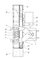
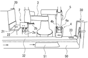
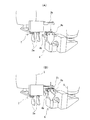
本発明の実施の形態について、添付図面を参照しつつ説明する。本発明に係る握り寿司製造装置は、双腕ロボット1と、シャリ玉ロボット20と、ネタ移載装置30と、皿搬送手段とを含んで構成され、更に必要に応じ、ネタ上にワサビを供給するサビ打ちロボット40を含んで構成される(図1)。
Embodiments of the present invention will be described with reference to the accompanying drawings. The nigiri sushi manufacturing apparatus according to the present invention includes a double-armed robot 1, a
双腕ロボット1は、垂直多関節ロボットであるシャリ玉移送アーム3とネタ移送アーム5の2つのアームを備えたロボットマニピュレータであり、シャリ玉移送アーム3のエンドエフェクタ(手先効果器)は,開閉動作する掴持ハンド2aを備えたシャリ玉把持ハンド2とされ、ネタ移送アーム5のエンドエフェクタは、開閉動作する整形ハンド4aを備えたネタ把持ハンド4とされる。シャリ玉把持ハンド2には、指形状の押し部材2bが水平方向に突設される。なお、垂直多関節ロボットの機構は周知であるので、詳細な説明は省略する。
The dual-arm robot 1 is a robot manipulator having two arms, a sushi
図1に示される第1の実施形態においては、双腕ロボット1の前を横切るようにネタ供給コンベア31が設置され、ネタ移載装置30はネタ供給コンベア31の下流端に配置されて、搬送されてくるネタをすくい取る機能を有する。ネタ供給コンベア31には、ネタ載置部となる上流端部(図1において右側端部)を残してカバー32が被せられる。カバー32の下流端部の一部には、後述するように昇降動作するネタ移載装置30のネタ移載機構34を逃がすための切除部33が設けられる(図1,2参照)。
In the first embodiment shown in FIG. 1, the
また、この実施形態の場合の皿搬送手段は、ネタ供給コンベア31と平行に配置される皿搬送コンベア50である。皿搬送コンベア50は、出来上がった寿司72を載せる皿51を1枚ずつ、後述する双腕ロボット1の正面の寿司成形位置に搬送し、且つ、寿司72が皿51に載せられる度に、予め設定される寿司の間隔分、皿51を移動させるよう動作する。皿搬送コンベア50は、皿51に所定数の寿司72が載せられた後、皿51を、先端の皿取り出し位置まで搬送する。
Further, the dish transporting means in the case of this embodiment is a
後述するように、双腕ロボット1のシャリ玉移送アーム3は、シャリ玉ロボット20により成形されて供出されるシャリ玉70を掴持ハンド2aにより掴持したシャリ玉把持ハンド2を、双腕ロボット1正面の寿司成形位置まで移動させるよう作用する。また、ネタ移送アーム5は、ネタ移載装置30からネタ71を受け取ったネタ把持ハンド4を、寿司成形位置まで移動させるよう作用する。以下、シャリ玉把持ハンド2の動きはすべてシャリ玉移送アーム3を介して制御され、また、ネタ把持ハンド4の動きはすべてネタ移送アーム5を介して制御されるので、その旨の説明は省略する。
As will be described later, the sushi
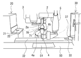
シャリ玉ロボット20は、双腕ロボット1の直近位置に配置され、握り寿司一貫分のシャリ玉70を成形し、双腕ロボット1に供出する。シャリ玉ロボット20は、箱型のケース内に、一貫分の寿司形状のシャリ玉を自動的に作り上げる成形部と、成形したシャリ玉を1つずつ、ケース上面のシャリ玉供給用テーブル面21に形成された供出口22からテーブル面21まで押し上げるリフターとを具備して成る上出し式の装置である。
The
シャリ玉ロボット20としては、例えば、特許第4878069号公報に開示されているような、公知の構成を採用することができる。
As the
ネタ供給コンベア31は、双腕ロボット1の前側を横切るように設置され、また、それと平行に皿搬送コンベア50が設置される。上述したようにネタ供給コンベア31には、両端部を残してカバー32が被せられ、搬送中のネタ71に塵埃等が付着することが防止される。ネタ供給コンベア31の上流端がネタ供給部となり、そこから人手により、あるいは、機械的に、ネタ71が適宜間隔置きに供給される。ネタ供給コンベア31の下流端には、ネタ移載装置30が設置される。
The
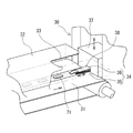
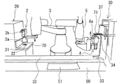
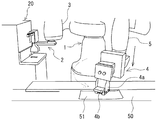
ネタ移載装置30は、例えば、図示せぬ可動フレームに支持されて進退動作するキャリア板35と、キャリア板35に緊張状態にて巻回される無端の移載ベルト36とから成るネタ移載機構34を備えたものとされる(図2、特開2018−174896号公報参照)。このネタ移載機構34は、箱状の昇降フレーム37内に、昇降フレーム37に形成された開口部38から進退可能となるように設置される。そして、図示せぬ昇降シリンダーの作用で昇降フレーム37ごと昇降動作する(図2〜8)。昇降フレーム37は、上昇端のネタ供給位置において、進退可能にされる。
The
このネタ移載装置30の場合、可動フレームと共にキャリア板35が進退動作し、それに伴って移載ベルト36が循環動作することにより、ネタ71をすくい取り又は排出する。即ち、後述するようにネタ移載機構34は、昇降シリンダーに駆動されて昇降フレーム37ごと上下動し、下降端においてネタ供給コンベア31からネタ71をすくい取り(図2)、上昇端において、ネタ把持ハンド4の整形ハンド4a間の受け板4b上に、そのネタ71を移載する(図3,4)。
In the case of the
サビ打ちロボット40は、例えば、ワサビの定量供給機とそこから延びるノズルとを含み、ノズルは、ネタ71を移載されたネタ把持ハンド4の整形ハンド4a間の受け板4b上方に位置し、ネタ71の到来に呼応して動作し、ネタ71上にワサビを定量供給する。後述するように、その後ネタ71上にシャリ玉70が載せられるので、ワサビはネタ71とシャリ玉の間に挟み込まれることになる。
The rusting
次に、上記構成の本発明に係る握り寿司製造装置の動作について説明するが、各構成部の動きを理解しやすいように、シャリ玉移送アーム3(シャリ玉把持ハンド2)関係の動作、ネタ移載装置30関係の動作、及び、ネタ移送アーム5(ネタ把持ハンド4)関係の動作に分けて説明する。上記のとおり、シャリ玉把持ハンド2の動きはすべてシャリ玉移送アーム3を介して制御され、ネタ把持ハンド4の動きはすべてネタ移送アーム5を介して制御される。なお、以下の動作(1)〜動作(19)は、必ずしもその順という訳ではなく、適宜入れ替えが可能である。
Next, the operation of the nigiri sushi manufacturing apparatus according to the present invention having the above configuration will be described. The operation related to the
シャリ玉移送アーム関係の動作
(1)シャリ玉ロボット20内において、一貫分の握り寿司形状のシャリ玉70が連続的に成形され、成形されたシャリ玉70が1つずつ、ケース上面のシャリ玉供給用テーブル面21に設けられた供出口22から、テーブル面21の高さまで押し上げられる(図5,6)。
(2)シャリ玉把持ハンド2が、シャリ玉供給用テーブル面21の供出口22上に移動する(図6)。その際シャリ玉把持ハンド2の掴持ハンド2aは開いていて、下向きの状態となっている。
(3)シャリ玉把持ハンド2がテーブル面21まで下降し、掴持ハンド2aが閉動作してシャリ玉を掴み、そのまま上昇する(図7)。
(4)シャリ玉把持ハンド2は、上昇端に達した後旋回し、双腕ロボット1の正面においてネタ71を保持して待機しているネタ把持ハンド4上に移動する(図8)。なお、シャリ玉把持ハンド2が先に移動して待機するようにしてもよいし、シャリ玉把持ハンド2とネタ把持ハンド4が同時に到来することとしてもよい。
(5)シャリ玉把持ハンド2の掴持ハンド2aはネタ把持ハンド4上において開動作し、掴持していたシャリ玉70を、ネタ把持ハンド4に保持されているネタ71上に落とす(図8)。
(6)ネタ把持ハンド4の整形ハンド4aは軽く開閉動作をしてシャリ玉70を適度に押し固め(握り操作1)、また、シャリ玉把持ハンド2は、ネタ把持ハンド4から外れる位置まで後退し、90度回転した後1又は複数回上下動し、指形状の押し部材2bでシャリ玉70を押してネタ71になじませると共に、形を整える(握り操作2)(図9)。握り操作1と握り操作2は、同時に又は交互に行い、また、握り操作1と握り操作2は複数回行うこととしてもよい。
(7)シャリ玉把持ハンド2は、その後シャリ玉供給用テーブル面21の供出口22上に移動し、シャリ玉ロボット20からのシャリ玉70の供出を待ち(図10,11)、以後上記動作を反復する。
Operations related to the sushi ball transfer arm (1) In the
(2) The rice
(3) The rice
(4) The rice
(5) The
(6) The shaping
(7) The sushi
ネタ移載装置30の動作
(8)ネタ移載装置30の移載機構34は、下降端において、キャリア板31が昇降フレーム37内に後退した状態で、ネタ71がネタ供給コンベア31上を搬送されてくるのを待つ(図5,8)。
(9)図示せぬセンサがネタ71の到来を感知すると、キャリア板31が移載ベルト32と一体にネタ供給コンベア31の表面に沿って前進し、先端部がネタ71に接する(図2)。その際移載ベルト32は、キャリア板31の移動方向とは逆方向(後ろ向き)に循環しているため、ネタ71がネタ供給コンベア31から移載ベルト32上にすくい上げられる。
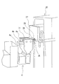
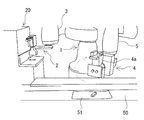
(10)ネタ71をすくい上げた後、移載ベルト32の循環動作は停止し、ネタ移載機構34はその状態のまま上昇し、上昇端において昇降フレーム37がネタ供給位置まで前進してネタ把持ハンド4の到来を待つ(図6)。
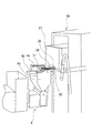
(11)ネタ移載機構34の下側にネタ把持ハンド4が到来すると、ネタ移載機構34は上記と逆の動きをし、即ち、キャリア板31が後退動作し、移載ベルト32が前向きに循環動作する結果、移載ベルト32上のネタ71は移載ベルト32から脱落してネタ把持ハンド4上に落ちる(図7,4)。
(12)その後ネタ移載機構34は、後退した状態のまま下降し、下降端において次のネタ71の到来を待つ(図8)。
Operation of the material transfer device 30 (8) In the
(9) When a sensor (not shown) detects the arrival of the
(10) After scooping up the
(11) When the material
(12) After that, the
ネタ移送アーム5(ネタ把持ハンド4)の動作
(13)ネタ移送アーム5は、整形ハンド4aが開いた状態のネタ把持ハンド4を正面向き、且つ、下向きにした状態(図5)から始動し、先ず、ネタ把持ハンド4を上向きに回動させた後、外方に90度旋回させて上昇させる(図6)。その際、ネタ移載機構34は、ネタ71を把持した状態で上昇端にて待機しているので、ネタ把持ハンド4はネタ移載機構34の下側に位置することになる。
(14)上記ネタ移載機構34の動作(上記動作(11))に伴って、ネタ把持ハンド4の整形ハンド4a間の受け板4b上にネタ71が移載される(図4,7)。
(15)その後ネタ把持ハンド4は、上向きのまま180度旋回して双腕ロボット1の正面の成形位置に移動し、その位置でシャリ玉把持ハンド2の到来を待つ(図8)。上記動作(4)において述べたように、シャリ玉把持ハンド2が先に移動して待機することもあり、また、シャリ玉把持ハンド2とネタ把持ハンド4が同時に到来することもある。
(16)シャリ玉把持ハンド2が到来して掴持ハンド2aが開動作をするに伴い、シャリ玉70がネタ把持ハンド4に把持されているネタ71上に載置され(図8)、次いで、上述した動作(6)における握り操作1及び握り操作2が行われる(図9)。
(17)その後ネタ把持ハンド4は、水平方向に適宜角度(50〜80度程度)回転すると共に、垂直方向に180度回転して下向きとなり、その状態のまま皿51の少し上にまで下降する(図10,11)。
(18)その位置において整形ハンド4aが開動作して寿司を解放し、皿51上に所定間隔置きに並べていく(図1)。上記動作(17)において、ネタ把持ハンド4が水平方向に適宜角度回転することにより、寿司72が、皿51上に体裁よく傾いた状態に並べられることになる。
(19)その後ネタ把持ハンド4は、上記と逆に動作して、図5に示すネタ71の待ち受け位置に戻り、ネタ71の供給を待つ。
Operation of the material transfer arm 5 (material gripping hand 4) (13) The
(14) Along with the operation of the material transfer mechanism 34 (the operation (11)), the
(15) After that, the material
(16) As the rice
(17) After that, the material
(18) At that position, the shaping
(19) After that, the material
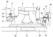
上記実施形態における皿搬送手段は、ネタ供給コンベアと平行に配置される皿搬送コンベア50であるが、これに代えて、双腕ロボット1の正面に設置されて、皿51を1枚ずつ定位置まで押し上げるリフター機能を有するものを採用することもできる。その場合、所定数の寿司72が並べられた皿51は、例えば、店員又は顧客が取り上げることになる。
The dish transporting means in the above embodiment is a
本発明に係る握り寿司製造装置は上記のとおりのものであって、複数のロボット要素で以て、寿司職人が握る動作が忠実に再現されることにより、寿司職人が握った寿司に近い食感と外観の握り寿司を製造することができるので、寿司職人がいない食堂や居酒屋等においても握り寿司を提供することが可能となり、また、本来の握り寿司を国内のみならず、海外に向けて継続して供給することが可能となるものであり、その産業上の利用可能性は極めて大である。 The nigiri sushi manufacturing apparatus according to the present invention is as described above, and by faithfully reproducing the movements held by the sushi chef with a plurality of robot elements, the texture is similar to that of sushi held by the sushi chef. Since it is possible to manufacture nigiri sushi with the appearance, it is possible to provide nigiri sushi even in restaurants and taverns where there are no sushi chefs, and the original nigiri sushi will be continued not only in Japan but also overseas. It is possible to supply the sushi, and its industrial utility is extremely high.
1 双腕ロボット
2 シャリ玉把持ハンド
2a 掴持ハンド
2b 押し部材
3 シャリ玉移送アーム
4 ネタ把持ハンド
4a 整形ハンド
4b 受け板
5 ネタ移送アーム
20 シャリ玉ロボット
30 ネタ移載装置
31 ネタ供給コンベア
34 移載機構
35 キャリア板
36 移載ベルト
40 サビ打ちロボット
50 皿搬送コンベア
70 シャリ玉
71 ネタ
72 寿司
1 Double-
30
Claims (9)
前記双腕ロボットの前記シャリ玉移送アーム側に配置されて、握り寿司一貫分のシャリ玉成形を行い、前記シャリ玉把持ハンドによる掴み上げ位置に供出するシャリ玉ロボットと、
前記双腕ロボットの前記ネタ移送アーム側に配置されて、前記ネタ把持ハンドにネタを移載するネタ移載装置と、
製造された寿司を載置するための皿を定位置に供給する皿搬送手段とを含み、
前記ネタ把持ハンドは、前記ネタ移載装置からネタを移載された後、前記双腕ロボット正面の寿司成形位置に移動し、前記シャリ玉把持ハンドは、前記シャリ玉ロボットからシャリ玉を掴み上げた後、前記寿司成形位置まで移動して、前記シャリ玉を前記ネタ把持ハンドにより保持されているネタの上に供給することを特徴とする握り寿司製造装置。 A dual-arm robot equipped with a sushi ball transfer arm, which is a vertical articulated arm equipped with a sushi ball gripping hand at the tip, and a material transfer arm, which is a vertical articulated arm equipped with a sushi ball gripping hand at the tip.
A sushi ball robot that is arranged on the side of the sushi ball transfer arm of the dual-arm robot, performs sushi ball molding for nigiri sushi consistently, and delivers it to a pick-up position by the sushi ball gripping hand.
A material transfer device that is arranged on the material transfer arm side of the dual-arm robot and transfers the material to the material gripping hand.
Including a dish transporting means that supplies a dish for placing the manufactured sushi in place.
The material gripping hand moves to the sushi forming position in front of the dual-arm robot after the material is transferred from the material transfer device, and the rice ball gripping hand picks up the rice balls from the rice ball robot. After that, the sushi sushi making apparatus is characterized by moving to the sushi forming position and supplying the rice sushi balls onto the material held by the material gripping hand.
Priority Applications (1)
| Application Number | Priority Date | Filing Date | Title |
|---|---|---|---|
| JP2020001978A JP7489055B2 (en) | 2020-01-09 | 2020-01-09 | Nigiri sushi making equipment |
Applications Claiming Priority (1)
| Application Number | Priority Date | Filing Date | Title |
|---|---|---|---|
| JP2020001978A JP7489055B2 (en) | 2020-01-09 | 2020-01-09 | Nigiri sushi making equipment |
Publications (2)
| Publication Number | Publication Date |
|---|---|
| JP2021108564A true JP2021108564A (en) | 2021-08-02 |
| JP7489055B2 JP7489055B2 (en) | 2024-05-23 |
Family
ID=77058188
Family Applications (1)
| Application Number | Title | Priority Date | Filing Date |
|---|---|---|---|
| JP2020001978A Active JP7489055B2 (en) | 2020-01-09 | 2020-01-09 | Nigiri sushi making equipment |
Country Status (1)
| Country | Link |
|---|---|
| JP (1) | JP7489055B2 (en) |
Cited By (1)
| Publication number | Priority date | Publication date | Assignee | Title |
|---|---|---|---|---|
| JP2023155022A (en) * | 2022-04-08 | 2023-10-20 | 株式会社タカラトミーアーツ | orbital toy |
Family Cites Families (2)
| Publication number | Priority date | Publication date | Assignee | Title |
|---|---|---|---|---|
| JP5603086B2 (en) | 2010-01-07 | 2014-10-08 | 鈴茂器工株式会社 | Shari-ball forming method and shari-ball forming apparatus |
| JP4878069B1 (en) | 2010-09-30 | 2012-02-15 | 鈴茂器工株式会社 | Sushi ball forming equipment |
-
2020
- 2020-01-09 JP JP2020001978A patent/JP7489055B2/en active Active
Cited By (1)
| Publication number | Priority date | Publication date | Assignee | Title |
|---|---|---|---|---|
| JP2023155022A (en) * | 2022-04-08 | 2023-10-20 | 株式会社タカラトミーアーツ | orbital toy |
Also Published As
| Publication number | Publication date |
|---|---|
| JP7489055B2 (en) | 2024-05-23 |
Similar Documents
| Publication | Publication Date | Title |
|---|---|---|
| CN213760518U (en) | Equipment for food production | |
| CN109521665B (en) | Automatic assembling and pressing mechanism for clock shell | |
| CN210223987U (en) | Full-automatic wafer lower and upper wax-loading return line | |
| JP2021108564A (en) | Hand-formed-like sushi producing device | |
| JP4926489B2 (en) | Lunch box assortment method and apparatus for sushi | |
| CN206536977U (en) | A fully automatic disc hot stamping machine | |
| JP6041310B2 (en) | Food gripping device and container packing device | |
| CN106241404B (en) | Stack-mold side-taking type tableware packaging system and packaging method | |
| GB2184418A (en) | A machine for boxing items in groups | |
| JP6379012B2 (en) | Goods transfer device | |
| JP4497479B2 (en) | Food arrangement method and apparatus | |
| US8104808B1 (en) | Dough ball lifter | |
| US8702140B2 (en) | Dough ball lifter | |
| MXPA05009225A (en) | Machine for automatically supplying plates and/or moulds for bakery products to a forming line. | |
| JPH01172123A (en) | Method for transshipping article | |
| JP2020158176A (en) | Goods transfer device | |
| JP6881869B2 (en) | Gunkanmaki molding transfer device | |
| CN113697509A (en) | Blowing balance equipment | |
| CN113349629A (en) | Food cooking machine | |
| JPH02192834A (en) | Transfer press | |
| CN117530475B (en) | Food production line | |
| CN222357145U (en) | Three-dimensional decoration system of cake | |
| JP7478217B2 (en) | Item storage frame | |
| CN218404670U (en) | Automatic material feeding machine | |
| JPH02238852A (en) | Baking of cracker and apparatus therefor |
Legal Events
| Date | Code | Title | Description |
|---|---|---|---|
| A80 | Written request to apply exceptions to lack of novelty of invention |
Free format text: JAPANESE INTERMEDIATE CODE: A80 Effective date: 20200130 |
|
| A621 | Written request for application examination |
Free format text: JAPANESE INTERMEDIATE CODE: A621 Effective date: 20230106 |
|
| A521 | Request for written amendment filed |
Free format text: JAPANESE INTERMEDIATE CODE: A523 Effective date: 20230118 |
|
| A977 | Report on retrieval |
Free format text: JAPANESE INTERMEDIATE CODE: A971007 Effective date: 20231221 |
|
| A131 | Notification of reasons for refusal |
Free format text: JAPANESE INTERMEDIATE CODE: A131 Effective date: 20240105 |
|
| A521 | Request for written amendment filed |
Free format text: JAPANESE INTERMEDIATE CODE: A523 Effective date: 20240206 |
|
| TRDD | Decision of grant or rejection written | ||
| A01 | Written decision to grant a patent or to grant a registration (utility model) |
Free format text: JAPANESE INTERMEDIATE CODE: A01 Effective date: 20240404 |
|
| A521 | Request for written amendment filed |
Free format text: JAPANESE INTERMEDIATE CODE: A523 Effective date: 20240426 |
|
| A61 | First payment of annual fees (during grant procedure) |
Free format text: JAPANESE INTERMEDIATE CODE: A61 Effective date: 20240501 |
|
| A521 | Request for written amendment filed |
Free format text: JAPANESE INTERMEDIATE CODE: A523 Effective date: 20240508 |
|
| A521 | Request for written amendment filed |
Free format text: JAPANESE INTERMEDIATE CODE: A523 Effective date: 20240509 |
|
| R150 | Certificate of patent or registration of utility model |
Ref document number: 7489055 Country of ref document: JP Free format text: JAPANESE INTERMEDIATE CODE: R150 |