JP2021132500A - Motor drive system - Google Patents
Motor drive system Download PDFInfo
- Publication number
- JP2021132500A JP2021132500A JP2020027555A JP2020027555A JP2021132500A JP 2021132500 A JP2021132500 A JP 2021132500A JP 2020027555 A JP2020027555 A JP 2020027555A JP 2020027555 A JP2020027555 A JP 2020027555A JP 2021132500 A JP2021132500 A JP 2021132500A
- Authority
- JP
- Japan
- Prior art keywords
- motor drive
- cooling
- heat dissipation
- dissipation capacity
- heat
- Prior art date
- Legal status (The legal status is an assumption and is not a legal conclusion. Google has not performed a legal analysis and makes no representation as to the accuracy of the status listed.)
- Granted
Links
- 238000001816 cooling Methods 0.000 claims abstract description 92
- 239000002826 coolant Substances 0.000 claims abstract description 16
- 230000017525 heat dissipation Effects 0.000 claims description 46
- 238000001514 detection method Methods 0.000 claims description 4
- 238000010438 heat treatment Methods 0.000 abstract 2
- 239000000498 cooling water Substances 0.000 description 35
- 239000004065 semiconductor Substances 0.000 description 19
- 230000000712 assembly Effects 0.000 description 7
- 238000000429 assembly Methods 0.000 description 7
- 238000000034 method Methods 0.000 description 5
- 238000010586 diagram Methods 0.000 description 4
- 239000007788 liquid Substances 0.000 description 4
- XLYOFNOQVPJJNP-UHFFFAOYSA-N water Substances O XLYOFNOQVPJJNP-UHFFFAOYSA-N 0.000 description 3
- IJGRMHOSHXDMSA-UHFFFAOYSA-N Atomic nitrogen Chemical compound N#N IJGRMHOSHXDMSA-UHFFFAOYSA-N 0.000 description 2
- -1 for example Substances 0.000 description 2
- 239000000463 material Substances 0.000 description 2
- HBMJWWWQQXIZIP-UHFFFAOYSA-N silicon carbide Chemical compound [Si+]#[C-] HBMJWWWQQXIZIP-UHFFFAOYSA-N 0.000 description 2
- 229910010271 silicon carbide Inorganic materials 0.000 description 2
- 238000011144 upstream manufacturing Methods 0.000 description 2
- 229910000838 Al alloy Inorganic materials 0.000 description 1
- RYGMFSIKBFXOCR-UHFFFAOYSA-N Copper Chemical compound [Cu] RYGMFSIKBFXOCR-UHFFFAOYSA-N 0.000 description 1
- 229910000881 Cu alloy Inorganic materials 0.000 description 1
- 239000000853 adhesive Substances 0.000 description 1
- 230000001070 adhesive effect Effects 0.000 description 1
- 230000002528 anti-freeze Effects 0.000 description 1
- 238000007664 blowing Methods 0.000 description 1
- 238000005219 brazing Methods 0.000 description 1
- 229910052802 copper Inorganic materials 0.000 description 1
- 239000010949 copper Substances 0.000 description 1
- 230000000694 effects Effects 0.000 description 1
- 239000007789 gas Substances 0.000 description 1
- 229910052757 nitrogen Inorganic materials 0.000 description 1
- 239000003921 oil Substances 0.000 description 1
- 230000002093 peripheral effect Effects 0.000 description 1
- 230000005855 radiation Effects 0.000 description 1
Images
Landscapes
- Inverter Devices (AREA)
Abstract
Description
本発明は、モータ駆動装置及び冷却装置を備えるモータ駆動システムに関する。 The present invention relates to a motor drive system including a motor drive device and a cooling device.
工作機械等のモータを駆動するモータ駆動装置は、駆動電流を生成するための部品として、パワー半導体素子を備えている。パワー半導体素子は、作動中に発熱する部品(以下、「発熱部品」ともいう)であるため、モータの運転中、冷却する必要がある。発熱部品を冷却する手法として、例えば、ファンモータを用いた送風等による空冷の他、流路に冷却媒体を流通させる液冷が知られている(例えば、特許文献1参照)。 A motor drive device that drives a motor such as a machine tool includes a power semiconductor element as a component for generating a drive current. Since a power semiconductor element is a component that generates heat during operation (hereinafter, also referred to as a “heat generating component”), it is necessary to cool the power semiconductor element during operation of the motor. As a method for cooling a heat-generating component, for example, in addition to air cooling by blowing air using a fan motor or the like, liquid cooling in which a cooling medium is circulated in a flow path is known (see, for example, Patent Document 1).
冷却媒体を用いる液冷は、空冷に比べて、発熱部品の温度上昇の抑制が容易である。そのため、例えば、熱膨張等の熱に関する問題点の改善を図ることができる。
しかし、複数のモータ駆動装置を備えた構成において、冷却媒体により放熱部品を冷却する場合、冷却装置からそれぞれのモータ駆動装置に冷却媒体を流通させるための配管を個別に設ける必要がある。そのため、発熱部品を冷却媒体により液冷する構成においては、システム構成が複雑になる、コストが増加する等が課題となっていた。
Liquid cooling using a cooling medium makes it easier to suppress the temperature rise of heat-generating components than air cooling. Therefore, for example, it is possible to improve problems related to heat such as thermal expansion.
However, in a configuration including a plurality of motor drive devices, when the heat radiation component is cooled by the cooling medium, it is necessary to individually provide a pipe for distributing the cooling medium from the cooling device to each motor drive device. Therefore, in the configuration in which the heat-generating component is liquid-cooled by the cooling medium, there are problems that the system configuration becomes complicated and the cost increases.
本発明の目的は、システム構成の簡素化及びコストの低減が可能なモータ駆動システムを提供することにある。 An object of the present invention is to provide a motor drive system capable of simplifying a system configuration and reducing costs.
本開示の一態様は、モータを駆動する複数のモータ駆動装置と、前記モータ駆動装置に冷却媒体を循環させることにより冷却する冷却装置と、を備え、前記モータ駆動装置は、発熱部品と、前記発熱部品を冷却する放熱器と、前記放熱器に接続され、内部に冷却媒体が流通する流路と、を備え、複数の前記モータ駆動装置の各々の前記流路は、隣接する前記モータ駆動装置の前記流路と互いに連通するように接続される、モータ駆動システムである。 One aspect of the present disclosure includes a plurality of motor drive devices for driving a motor and a cooling device for cooling by circulating a cooling medium in the motor drive device. A radiator for cooling the heat-generating component and a flow path connected to the radiator for the cooling medium to flow inside are provided, and each of the flow paths of the plurality of motor drive devices is adjacent to the motor drive device. It is a motor drive system connected to the flow path of the above so as to communicate with each other.
本発明によれば、システム構成の簡素化及びコストの低減が可能なモータ駆動システムを提供することができる。 According to the present invention, it is possible to provide a motor drive system capable of simplifying the system configuration and reducing the cost.
以下、本発明に係るモータ駆動システムの実施形態について説明する。
本明細書に添付した図面は、いずれも模式図であり、理解のしやすさを考慮して、各部の形状、縮尺、縦横の寸法比等を、実物から変更又は誇張している。
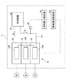
図1は、本実施形態におけるモータ駆動システム1の構成図である。図1に示すように、モータ駆動システム1は、モータ駆動装置10、冷却装置20、流量センサ30、放熱能力算出部40及び駆動電流制御部50を備えている。また、各モータ駆動装置10には、モータMが接続されている。
Hereinafter, embodiments of the motor drive system according to the present invention will be described.
The drawings attached to the present specification are all schematic views, and the shape, scale, aspect ratio, etc. of each part are changed or exaggerated from the actual product in consideration of ease of understanding.
FIG. 1 is a configuration diagram of a motor drive system 1 according to the present embodiment. As shown in FIG. 1, the motor drive system 1 includes a
モータ駆動装置10は、モータMに駆動電流を出力する装置である。図1では、3台のモータ駆動装置10が設けられ、それぞれのモータ駆動装置10が個別に配置されたモータMにそれぞれ接続された例を示している。3台のモータ駆動装置10は、隣接して配置されている。以下、3台のモータ駆動装置10の集合体を「モータ駆動ユニット11」ともいう。なお、モータ駆動システム1において、モータMの数は、3台に限らず、2台以下でもよいし、4台以上でもよい。モータ駆動装置10は、用意されたモータMの数だけ設置される。
The
各モータ駆動装置10の放熱能力は、すべて同じである。放熱能力とは、モータMの駆動時に、モータ駆動装置10の内部に設けられたヒートシンク本体130(後述)において放熱可能な熱量(kW)の最大値である。後述するように、3台のモータ駆動装置10のヒートシンク120(冷却管140)は、冷却装置20から供給される冷却水Wが順に通過するように接続されている。
The heat dissipation capacity of each
冷却装置20は、モータ駆動ユニット11に冷却水W(冷却媒体)を循環させることにより、各モータ駆動装置10の内部に設けられたヒートシンク本体130を冷却する装置である。冷却装置20は、冷却水Wから熱を吸収する熱交換器(不図示)を備えている。冷却装置20と各モータ駆動装置10との間は、冷却水配管21及び22により接続されている。冷却水配管21は、冷却水Wを冷却装置20からモータ駆動ユニット11に供給するための配管である。冷却水配管22は、モータ駆動ユニット11から排出された冷却水Wを冷却装置20に戻すための配管である。
The
流量センサ(流量検出部)30は、冷却装置20からモータ駆動ユニット11に供給される冷却水の流量(m3/s)を検出する装置である。流量センサ30で検出された冷却水の流量値は、放熱能力算出部40へ送信される。なお、図1では、流量センサ30を冷却水配管21に設けた例を示しているが、流量センサ30は、モータ駆動ユニット11の運転時に、冷却装置20から供給される冷却水の流量を検出することができれば、どこに設けられていてもよい。
The flow rate sensor (flow rate detection unit) 30 is a device that detects the flow rate (m 3 / s) of the cooling water supplied from the
放熱能力算出部40は、モータ駆動ユニット11の放熱能力を算出する。放熱能力算出部40は、流量センサ30で検出された冷却水Wの流量に基づいて、3台のモータ駆動装置10の合計の放熱能力(熱量)を、モータ駆動ユニット11の放熱能力として算出する。
駆動電流制御部50は、放熱能力算出部40で算出された放熱能力に基づいて、モータ駆動ユニット11を構成する各モータ駆動装置10の駆動電流制限レベルを調整する。駆動電流制限レベルとは、モータ駆動装置10からモータMへ供給される駆動電流の上限値である。モータ駆動装置10において、モータMを駆動するための駆動電流は、パワー半導体モジュール110(後述)を含む駆動回路から出力される。駆動電流制御部50は、放熱能力算出部40で算出された放熱能力に基づいて、各モータ駆動装置10の駆動電流制限レベルを同一レベルに調整する。
The heat dissipation
The drive
放熱能力算出部40及び駆動電流制御部50は、例えば、CPU(中央処理装置)、メモリを含むマイクロプロセッサにより構成される。放熱能力算出部40及び駆動電流制御部50は、所定のアプリケーションプログラムを読みだして実行することにより、各ハードウェアと協働して、後述する機能を実現する。
The heat dissipation
次に、モータ駆動装置10に設けられたヒートシンクアッセンブリ100の構成について説明する。
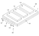
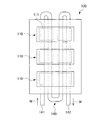
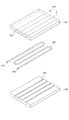
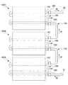
図2は、ヒートシンクアッセンブリ100の斜視図である。図3は、ヒートシンクアッセンブリ100の平面図である。図4は、ヒートシンク本体130の分解斜視図である。図5は、モータ駆動ユニット11におけるヒートシンクアッセンブリ100の接続形態を示す概念図である。なお、図5では、パワー半導体モジュール110(後述)の図示を省略している。
Next, the configuration of the
FIG. 2 is a perspective view of the
図2に示すように、ヒートシンクアッセンブリ100は、複数のパワー半導体モジュール110と、ヒートシンク120とを備えている。パワー半導体モジュール110は、図3に示すように、複数のパワー半導体素子(発熱部品)111を及びその周辺素子(不図示)が配置されたアッセンブリモジュールである。パワー半導体素子としては、例えば、SiC(シリコンカーバイド)等の大電流、高耐電圧に対応した半導体素子が挙げられる。なお、図3に示すパワー半導体素子111の形状、個数、配置等は一例であり、図示の例に限定されない。パワー半導体モジュール110は、図2に示すように、ヒートシンク120の冷却面Fの上に実装されている。
As shown in FIG. 2, the
ヒートシンク120は、パワー半導体モジュール110(パワー半導体素子111)で発生した熱を外部に放熱するための放熱装置である。ヒートシンク120は、ヒートシンク本体(放熱器)130と、冷却管(流路)140と、を備えている。
ヒートシンク本体130は、冷却面Fに設置されたパワー半導体モジュール110を冷却する構造体である。ヒートシンク本体130は、水冷板(水冷式の冷却板)として構成されており、内部に冷却管140(後述)が収納されている。
The
The
図4に示すように、ヒートシンク本体130は、第1冷却板131と、第2冷却板132と、を備えている。
第1冷却板131は、ヒートシンク本体130(ヒートシンク120)の冷却面Fを形成する板状の部材である。第1冷却板131は、厚さ方向において、冷却管140の半分(図中、上側の半分)が収納される複数の溝133を備えている。溝133は、第1冷却板131の長手方向に沿って設けられている。
As shown in FIG. 4, the heat sink
The
第2冷却板132は、冷却管140を間に挟んで、第1冷却板131とは反対側に配置される板状の部材である。第2冷却板132は、厚さ方向において、冷却管140の残りの半分(図中、下側の半分)が収納される複数の溝134を備えている。溝134は、第2冷却板132の長手方向に沿って設けられている。第1冷却板131の溝133と第2冷却板132の溝134は、ヒートシンク120を平面視した場合に、一致する位置に設けられている。
The
第1冷却板131及び第2冷却板132は、例えば、アルミニウム合金、銅合金等の熱伝導性の高い材料により形成される。図4に示すように、第1冷却板131の溝133と第2冷却板132の溝134との間に冷却管140を挟み込み、2つの冷却板を接合することにより、ヒートシンク120を得ることができる。第1冷却板131、第2冷却板132及び冷却管140は、例えば、ロウ付け、圧入、熱伝導性及び耐熱性を有する接着剤を用いた接着等の手法により接合することができる。なお、図4に示す冷却管140の形状等は一例であり、図示の例に限定されない。
The
冷却管(流路)140は、内部に冷却水Wが流通するパイプ状の部材である。冷却管140は、例えば、銅等の熱伝導性の高い材料により形成される。図4に示すように、冷却管140の入口部141には、冷却装置20(図1参照)から供給された冷却水W又は上流側のモータ駆動装置10(ヒートシンク120)から排出された冷却水Wが流入する。冷却管140に流入した冷却水Wは、冷却管140の内部を流通しながら、主にパワー半導体素子111が設けられた位置において、冷却面Fの熱を吸収(熱交換)する。冷却管140の内部を流通した冷却水Wは、出口部142から排出され、下流側のモータ駆動装置10(ヒートシンク120)又は冷却装置20に送られる。なお、図4等に示す冷却水Wの流通方向は一例であり、図示の例に限定されない。
The cooling pipe (flow path) 140 is a pipe-shaped member through which the cooling water W flows. The
図5に示すように、3台のモータ駆動装置10の各ヒートシンクアッセンブリ100は、隣接する他のヒートシンクアッセンブリ100と互いに連通するように接続されている。図5では、ヒートシンクアッセンブリ100の識別を容易にするため、冷却水Wの供給側(上流側)から排出側(下流側)に向かって、ヒートシンクアッセンブリ100の符号を、ヒートシンクアッセンブリ100A、100B、100Cと記載している。
As shown in FIG. 5, each
図5に示すように、ヒートシンクアッセンブリ100Aの冷却管140の出口部142と、ヒートシンクアッセンブリ100Bの冷却管140の入口部141との間、及び、ヒートシンクアッセンブリ100Bの冷却管140の出口部142と、ヒートシンクアッセンブリ100Cの冷却管140の入口部141との間は、それぞれU字形配管150と配管アダプタ160により接続されている。
As shown in FIG. 5, between the
このように、本実施形態のモータ駆動ユニット11において、3台のモータ駆動装置10のそれぞれの冷却管140は、U字形配管150と配管アダプタ160によって、隣接する他のモータ駆動装置10の冷却管140と互いに連通するように接続されている。
また、冷却管140の入口部141と冷却水配管21との間、及び、冷却管140の出口部142と冷却水配管22との間は、それぞれ配管アダプタ160により接続されている。
なお、図5に示す構成において、ヒートシンクアッセンブリ100A、100B及び100Cの側面が互いに接触するような構成としてもよい。このような構成とすることにより、U字形配管150の長さをより短くできる。
As described above, in the
Further, the
In the configuration shown in FIG. 5, the side surfaces of the
上記構成において、冷却装置20(図1参照)から冷却水配管21を介して供給される冷却水Wは、ヒートシンクアッセンブリ100A、100B、100Cの順に各冷却管140の内部を流通しながら、各ヒートシンクアッセンブリ100に実装されたパワー半導体素子111(図3参照)の熱を吸収する。ヒートシンクアッセンブリ100A、100B、100Cの順に流通した冷却水Wは、冷却水配管22を介して冷却装置20に戻される。冷却装置20へ戻された冷却水Wは、熱交換器(不図示)により熱が吸収されて冷却され、再び冷却水配管21を介してヒートシンクアッセンブリ100A〜100Cに供給される。
In the above configuration, the cooling water W supplied from the cooling device 20 (see FIG. 1) via the cooling
次に、モータ駆動システム1において、モータ駆動装置10の駆動電流制限レベルを調整する制御について説明する。
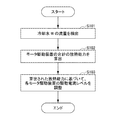
図6は、モータ駆動装置10の駆動電流制限レベルを調整する制御の処理手順を示すフローチャートである。図6に示す制御は、定期的又は所定のタイミングで実施される。
Next, in the motor drive system 1, control for adjusting the drive current limit level of the
FIG. 6 is a flowchart showing a control processing procedure for adjusting the drive current limit level of the
図6に示すステップS101において、流量センサ30により冷却装置20からモータ駆動ユニット11に供給される冷却水Wの流量を検出する。
ステップS102において、放熱能力算出部40は、流量センサ30で検出された冷却水Wの流量に基づいて、3台のモータ駆動装置10の合計の放熱能力(熱量)を算出する。
ステップS103において、駆動電流制御部50は、放熱能力算出部40で算出された放熱能力に基づいて、モータ駆動ユニット11を構成する各モータ駆動装置10の駆動電流制限レベルを調整する。これにより、各モータ駆動装置10は、同一の駆動電流制限レベルに設定される。
In step S101 shown in FIG. 6, the
In step S102, the heat dissipation
In step S103, the drive
上述した本実施形態のモータ駆動システム1によれば、例えば、以下のような効果を奏する。
本実施形態のモータ駆動ユニット11において、各モータ駆動装置10の冷却管(流路)140は、隣接する他のモータ駆動装置10の冷却管140と互いに連通するように接続される。これによれば、冷却装置20から各モータ駆動装置10に冷却水Wを流通させるための配管を個別に設ける従来の構成に比べて、配管数、配管長さを削減できるため、システム構成の簡素化及びコストの低減を図ることができる。
According to the motor drive system 1 of the present embodiment described above, for example, the following effects are obtained.
In the
本実施形態のモータ駆動システム1によれば、冷却装置20の仕様を適切に選定することにより、モータ駆動装置10の冷却能力を制御できる。例えば、放熱能力(最大値)が100℃で50kWのモータ駆動装置10の場合、冷却装置20からは、この放熱能力に見合った流量又は温度の冷却水Wが供給される。このシステムにおいて、モータ駆動装置10を50℃で50kWの放熱能力で運転する場合、2倍の流量又は1/2の温度の冷却水Wを供給可能な冷却装置20を選定すれば、同じモータ駆動装置10を、実質的に50℃で50kWの放熱能力で運転することができる。モータ駆動システム1が複数のモータ駆動装置10を備える場合には、複数のモータ駆動装置10の合計の放熱能力に基づいて冷却装置20を選定すればよい。
According to the motor drive system 1 of the present embodiment, the cooling capacity of the
本実施形態のモータ駆動システム1によれば、放熱能力算出部40において、モータ駆動ユニット11に供給される冷却水Wの流量に基づいて、3台のモータ駆動装置10の合計の放熱能力が算出される。そして、駆動電流制御部50において、放熱能力算出部40で算出された放熱能力に基づいて、モータ駆動ユニット11を構成する各モータ駆動装置10の駆動電流制限レベルが調整される。これによれば、例えば、冷却装置20の放熱能力が10kW、モータ駆動装置10の放熱能力(最大値)が50kWである場合、各モータ駆動装置10の駆動電流制限レベルが、放熱能力10kWに相当する駆動電流となるように調整される。これにより、モータ駆動装置10の放熱能力が最大で50kWであっても、モータ駆動装置10からモータMに対して、放熱能力10kWに相当する駆動電流が出力される。すなわち、モータ駆動装置10からは、冷却装置20の放熱能力を超えないレベルの駆動電流がモータMに出力される。したがって、本実施形態のモータ駆動システム1によれば、設置されている冷却装置20の放熱能力に応じた運転が可能となる。
According to the motor drive system 1 of the present embodiment, the heat dissipation
(変形形態)
実施形態のモータ駆動システム1において、ヒートシンク本体130(図2参照)の温度を検出する温度センサ(温度検出部)を設けた構成としてもよい。本構成において、モータ駆動装置10からモータMに規定の駆動電流を出力し、その場合のヒートシンク本体130の温度を温度センサで検出する。そして、放熱能力算出部40において、温度センサで検出されたヒートシンク本体130の温度に基づいて放熱能力を算出するようにしてもよい。
(Transformed form)
In the motor drive system 1 of the embodiment, a temperature sensor (temperature detection unit) for detecting the temperature of the heat sink main body 130 (see FIG. 2) may be provided. In this configuration, a specified drive current is output from the
実施形態では、ヒートシンクアッセンブリ100A、100B及び100Cを平面的に隣接するように配置した例について説明したが、ヒートシンクアッセンブリ100A、100B及び100Cは、厚さ方向に並べて配置してもよい。
実施形態では、冷却媒体を冷却水とした例について説明したが、冷却媒体は、水以外の液体、例えば、油、不凍液等でもよいし、窒素等の気体でもよい。
実施形態のヒートシンク本体130(液冷)に、ファンモータによる空冷を組み合わせた構成としてもよい。
In the embodiment, an example in which the
In the embodiment, an example in which the cooling medium is cooling water has been described, but the cooling medium may be a liquid other than water, for example, oil, antifreeze, or a gas such as nitrogen.
The heat sink main body 130 (liquid cooling) of the embodiment may be combined with air cooling by a fan motor.
1:モータ駆動システム、10:モータ駆動装置、11:モータ駆動ユニット、20:冷却装置、30:流量センサ、40:放熱能力算出部、50:駆動電流制御部、100:ヒートシンクアッセンブリ、110:パワー半導体モジュール、111:パワー半導体素子、120:ヒートシンク、130:ヒートシンク本体、140:冷却管 1: Motor drive system, 10: Motor drive device, 11: Motor drive unit, 20: Cooling device, 30: Flow sensor, 40: Heat dissipation capacity calculation unit, 50: Drive current control unit, 100: Heat sink assembly, 110: Power Semiconductor module, 111: Power semiconductor element, 120: Heat sink, 130: Heat sink body, 140: Cooling tube
Claims (4)
前記モータ駆動装置に冷却媒体を循環させることにより冷却する冷却装置と、を備え、
前記モータ駆動装置は、
発熱部品と、
前記発熱部品を冷却する放熱器と、
前記放熱器に接続され、内部に冷却媒体が流通する流路と、を備え、
複数の前記モータ駆動装置の各々の前記流路は、隣接する前記モータ駆動装置の前記流路と互いに連通するように接続される、モータ駆動システム。 Multiple motor drive devices that drive motors,
The motor drive device is provided with a cooling device for cooling by circulating a cooling medium.
The motor drive device is
Heat-generating parts and
A radiator that cools the heat generating parts and
It is provided with a flow path connected to the radiator and through which a cooling medium flows.
A motor drive system in which each of the flow paths of the plurality of motor drive devices is connected so as to communicate with the flow paths of the adjacent motor drive devices.
前記放熱能力算出部が算出した放熱能力に基づいて、前記モータ駆動装置の駆動電流制限レベルを調整する駆動電流制御部と、
を備える、請求項1に記載のモータ駆動システム。 A heat dissipation capacity calculation unit that calculates the heat dissipation capacity of the radiator, and
A drive current control unit that adjusts the drive current limit level of the motor drive device based on the heat dissipation capacity calculated by the heat dissipation capacity calculation unit.
The motor drive system according to claim 1.
前記放熱能力算出部は、前記流量検出部で検出される冷却媒体の流量に基づいて放熱能力を算出する、請求項2に記載のモータ駆動システム。 Equipped with a flow rate detector that detects the flow rate of the cooling medium
The motor drive system according to claim 2, wherein the heat dissipation capacity calculation unit calculates the heat dissipation capacity based on the flow rate of the cooling medium detected by the flow rate detection unit.
前記放熱能力算出部は、モータに規定の駆動電流を出力した場合に前記温度検出部で検出された前記放熱器の温度に基づいて放熱能力を算出する、請求項2に記載のモータ駆動システム。 A temperature detector for detecting the temperature of the radiator is provided.
The motor drive system according to claim 2, wherein the heat dissipation capacity calculation unit calculates the heat dissipation capacity based on the temperature of the radiator detected by the temperature detection unit when a specified drive current is output to the motor.
Priority Applications (1)
| Application Number | Priority Date | Filing Date | Title |
|---|---|---|---|
| JP2020027555A JP7436237B2 (en) | 2020-02-20 | 2020-02-20 | motor drive system |
Applications Claiming Priority (1)
| Application Number | Priority Date | Filing Date | Title |
|---|---|---|---|
| JP2020027555A JP7436237B2 (en) | 2020-02-20 | 2020-02-20 | motor drive system |
Publications (2)
| Publication Number | Publication Date |
|---|---|
| JP2021132500A true JP2021132500A (en) | 2021-09-09 |
| JP7436237B2 JP7436237B2 (en) | 2024-02-21 |
Family
ID=77551352
Family Applications (1)
| Application Number | Title | Priority Date | Filing Date |
|---|---|---|---|
| JP2020027555A Active JP7436237B2 (en) | 2020-02-20 | 2020-02-20 | motor drive system |
Country Status (1)
| Country | Link |
|---|---|
| JP (1) | JP7436237B2 (en) |
Citations (8)
| Publication number | Priority date | Publication date | Assignee | Title |
|---|---|---|---|---|
| JP2006149064A (en) * | 2004-11-18 | 2006-06-08 | Toyota Motor Corp | Vehicle drive system and vehicle equipped with the same |
| JP2010136609A (en) * | 2008-11-04 | 2010-06-17 | Fuji Electric Systems Co Ltd | Cooling capacity measurement method for inverter device |
| JP2015139333A (en) * | 2014-01-24 | 2015-07-30 | Ntn株式会社 | Drive control device of motor-mounted automobile |
| JP2017135919A (en) * | 2016-01-29 | 2017-08-03 | 公益財団法人岡山県産業振興財団 | High voltage unit to be used in inverter device and inverter device using the same |
| JP2018042414A (en) * | 2016-09-09 | 2018-03-15 | 日産自動車株式会社 | Cooling abnormality detection device |
| JP2018206802A (en) * | 2017-05-30 | 2018-12-27 | ファナック株式会社 | Heat sink and heat sink assembly |
| JP2019031200A (en) * | 2017-08-08 | 2019-02-28 | トヨタ自動車株式会社 | Vehicle cooling device |
| JP2019110672A (en) * | 2017-12-18 | 2019-07-04 | Ntn株式会社 | Driving control device of motor-mounted automobile |
-
2020
- 2020-02-20 JP JP2020027555A patent/JP7436237B2/en active Active
Patent Citations (8)
| Publication number | Priority date | Publication date | Assignee | Title |
|---|---|---|---|---|
| JP2006149064A (en) * | 2004-11-18 | 2006-06-08 | Toyota Motor Corp | Vehicle drive system and vehicle equipped with the same |
| JP2010136609A (en) * | 2008-11-04 | 2010-06-17 | Fuji Electric Systems Co Ltd | Cooling capacity measurement method for inverter device |
| JP2015139333A (en) * | 2014-01-24 | 2015-07-30 | Ntn株式会社 | Drive control device of motor-mounted automobile |
| JP2017135919A (en) * | 2016-01-29 | 2017-08-03 | 公益財団法人岡山県産業振興財団 | High voltage unit to be used in inverter device and inverter device using the same |
| JP2018042414A (en) * | 2016-09-09 | 2018-03-15 | 日産自動車株式会社 | Cooling abnormality detection device |
| JP2018206802A (en) * | 2017-05-30 | 2018-12-27 | ファナック株式会社 | Heat sink and heat sink assembly |
| JP2019031200A (en) * | 2017-08-08 | 2019-02-28 | トヨタ自動車株式会社 | Vehicle cooling device |
| JP2019110672A (en) * | 2017-12-18 | 2019-07-04 | Ntn株式会社 | Driving control device of motor-mounted automobile |
Also Published As
| Publication number | Publication date |
|---|---|
| JP7436237B2 (en) | 2024-02-21 |
Similar Documents
| Publication | Publication Date | Title |
|---|---|---|
| JP6164304B2 (en) | Manufacturing method of semiconductor module cooler, semiconductor module cooler, semiconductor module, and electrically driven vehicle | |
| Jörg et al. | Direct single impinging jet cooling of a MOSFET power electronic module | |
| JP6365691B2 (en) | Semiconductor device | |
| JP5070014B2 (en) | Heat dissipation device | |
| US8522570B2 (en) | Integrated circuit chip cooling using magnetohydrodynamics and recycled power | |
| JP2006511787A (en) | Channel flat fin heat exchange system, apparatus and method | |
| TW200529733A (en) | Liquid cooling system and electronic apparatus having the same therein | |
| CN106486433B (en) | IGBT radiator | |
| KR100888390B1 (en) | Cooling device and system for a plasma arc torch and associated method | |
| JP3201784U (en) | Cooling device for computer arithmetic unit | |
| JP5206483B2 (en) | Power converter cooling system | |
| CN103348199B (en) | Liquid-cooling system and the method for cooling at least one heat generating component | |
| JP4697171B2 (en) | COOLING DEVICE AND ELECTRONIC DEVICE HAVING THE SAME | |
| KR101282780B1 (en) | The cooling equipment for separated multi-phase inverter | |
| KR20190100760A (en) | Rapid cooling apparatus using thermoelectric element | |
| JP7436237B2 (en) | motor drive system | |
| CN116301258A (en) | A temperature control and cooling system for chip testing | |
| JP2008235572A (en) | Electronic component cooling device | |
| JP4340890B2 (en) | Fever detection device | |
| KR19990024929A (en) | Cooling device using thermoelectric cooling module | |
| KR200235565Y1 (en) | Aluminium Heat-Sink Structure for Linear Power Amplifier Unit of Liquid Cooling System with Heat Conductibility of High Efficiency | |
| JP4517962B2 (en) | Cooling device for electronic equipment | |
| CN108389843B (en) | Liquid cooling cooling system | |
| JP3678996B2 (en) | Cooling system | |
| JP2008106958A (en) | Heat exchanger |
Legal Events
| Date | Code | Title | Description |
|---|---|---|---|
| A621 | Written request for application examination |
Free format text: JAPANESE INTERMEDIATE CODE: A621 Effective date: 20221219 |
|
| A977 | Report on retrieval |
Free format text: JAPANESE INTERMEDIATE CODE: A971007 Effective date: 20230727 |
|
| A131 | Notification of reasons for refusal |
Free format text: JAPANESE INTERMEDIATE CODE: A131 Effective date: 20230829 |
|
| A521 | Request for written amendment filed |
Free format text: JAPANESE INTERMEDIATE CODE: A523 Effective date: 20230915 |
|
| A131 | Notification of reasons for refusal |
Free format text: JAPANESE INTERMEDIATE CODE: A131 Effective date: 20231121 |
|
| A521 | Request for written amendment filed |
Free format text: JAPANESE INTERMEDIATE CODE: A523 Effective date: 20231215 |
|
| TRDD | Decision of grant or rejection written | ||
| A01 | Written decision to grant a patent or to grant a registration (utility model) |
Free format text: JAPANESE INTERMEDIATE CODE: A01 Effective date: 20240109 |
|
| A61 | First payment of annual fees (during grant procedure) |
Free format text: JAPANESE INTERMEDIATE CODE: A61 Effective date: 20240208 |
|
| R150 | Certificate of patent or registration of utility model |
Ref document number: 7436237 Country of ref document: JP Free format text: JAPANESE INTERMEDIATE CODE: R150 |