JP2021173473A - Whole building air conditioning system - Google Patents
Whole building air conditioning system Download PDFInfo
- Publication number
- JP2021173473A JP2021173473A JP2020077406A JP2020077406A JP2021173473A JP 2021173473 A JP2021173473 A JP 2021173473A JP 2020077406 A JP2020077406 A JP 2020077406A JP 2020077406 A JP2020077406 A JP 2020077406A JP 2021173473 A JP2021173473 A JP 2021173473A
- Authority
- JP
- Japan
- Prior art keywords
- air
- building
- space
- conditioning
- conditioning system
- Prior art date
- Legal status (The legal status is an assumption and is not a legal conclusion. Google has not performed a legal analysis and makes no representation as to the accuracy of the status listed.)
- Granted
Links
Images





Landscapes
- Central Air Conditioning (AREA)
- Duct Arrangements (AREA)
Abstract
【課題】ダクト施工やメンテナンスが不要であり、空調システムの構成を簡素化できる全館空調システムを提供する。
【解決手段】全館空調システム100は、建物H内の二階部分の非居室空間に設けられた空調室1と、空調室1内に配置された空調機2並びに換気装置3と、空調室1の一部に設けられた建物H内の空気の吸込口4並びに建物H内への空調空気の給気口5と、を備え、空調空気の給気口5が建物H内の階間空間6に連通し、建物H内の階間空間6を形成する一階の天井面7及び二階の床面8に建物H内へ空調空気を供給する吹出口9を有し、建物H内の空気と外気とを空調室1内に取り入れ、空調機2にて温度調節した空調空気を、階間空間6を経由して建物H内へ供給する。
【選択図】図1PROBLEM TO BE SOLVED: To provide an air-conditioning system for a whole building which does not require duct construction or maintenance and can simplify the configuration of an air-conditioning system.
SOLUTION: The whole building air conditioning system 100 includes an air conditioning room 1 provided in a non-living room space on the second floor in a building H, an air conditioner 2 and a ventilation device 3 arranged in the air conditioning room 1, and an air conditioning room 1. A part of the building H is provided with an air suction port 4 and an conditioned air air supply port 5 into the building H, and the conditioned air air supply port 5 is provided in the floor space 6 in the building H. The ceiling surface 7 on the first floor and the floor surface 8 on the second floor, which communicate with each other to form the interfloor space 6 in the building H, have an air outlet 9 for supplying conditioned air into the building H, and the air and the outside air in the building H are provided. Is taken into the air-conditioning room 1, and the air-conditioned air whose temperature is controlled by the air-conditioner 2 is supplied into the building H via the inter-floor space 6.
[Selection diagram] Fig. 1
Description
本発明は、一般住宅などの建物内全体の空調並びに換気を行うことができる全館空調システムに関する。 The present invention relates to a whole building air conditioning system capable of air conditioning and ventilation of the entire building such as a general house.
一般住宅などの建物内全体の空調並びに換気を行う全館空調システムについては、従来、様々な構造、機能を有するものが提案されているが、本発明に関連するものとして、例えば、特許文献1に記載された「セントラル空調システム」あるいは特許文献2に記載された「住宅用空調システム」などがある。
Conventionally, a system having various structures and functions has been proposed as an air-conditioning system for the entire building such as a general house, which air-conditions and ventilates the entire building. However, as related to the present invention, for example,
特許文献1に記載された「セントラル空調システム」は、空気取り入れ口を有し、小屋裏に配置される断熱材で包囲された蓄熱室と、蓄熱室内に配備されるエアコン及びダクト用換気扇と、ダクト用換気扇から住宅内の各区画空間に延びる断熱ダクトとから成り、温度調整されてエアコンから出る温冷気が蓄熱室内においてダクト用換気扇内に取り込まれ、ダクト用換気扇から断熱ダクトを通って各区画空間に給気されるようにしたものである。
The "central air conditioning system" described in
特許文献2に記載された「住宅用空調システム」は、住宅内の非居住空間に設けられた空調室と、空調室内に設置された空調機と、空調室の外部の空気である外部空気を空調室内に導入する外部空気導入手段と、空調機により調整された調整空気と外部空気導入手段により導入された外部空気とが混合された混合空気を空調室から複数の部屋に供給する混合空気供給手段と、を備える住宅用空調システムにおいて、混合空気供給手段は、空調室から延びる上流側給気ダクトと、上流側給気ダクトの下流側において分岐して延びる複数の下流側給気ダクトと、複数の下流側給気ダクトにそれぞれ設けられた複数の送風機と、を備えたものである。
The "residential air-conditioning system" described in
特許文献1に記載された「セントラル空調システム」及び特許文献2に記載された「住宅用空調システム」は、それぞれ所定の長所を有しているが、何れの空調システムも複数のダクトを必須要件としているので、ダクト施工に多くの資材と労力が必要であり、空調システムの構成も複雑である。
The "central air-conditioning system" described in
また、施工後のダクトについては、ダクト内の清掃などのメンテナンスが必要であり、特に、住宅のダクトは小径ダクトが用いられるため、ダクト内の清掃が困難であり、メンテナンス作業にも多大な労力と時間が必要である。 In addition, maintenance such as cleaning the inside of the duct is required for the duct after construction. In particular, since a small-diameter duct is used for the duct in a house, it is difficult to clean the inside of the duct, and a great deal of labor is required for maintenance work. And time is needed.
そこで、本発明が解決しようとする課題は、ダクト施工やメンテナンスが不要であり、空調システムの構成を簡素化できる全館空調システムを提供することにある。 Therefore, an object to be solved by the present invention is to provide an air-conditioning system for the entire building, which does not require duct construction or maintenance and can simplify the configuration of the air-conditioning system.
本発明に係る第一の全館空調システムは、
建物内の非居室空間(天井裏空間及び床下空間を除く)に設けられた空調室と、
前記空調室内に配置された空調機並びに前記建物内に設置された換気装置と、
前記空調室の一部に設けられた前記建物内の空気の吸込口並びに前記建物内への空調空気の給気口と、を備え、
前記空調空気の給気口が前記建物内の階間空間に連通し、
前記建物内の階間空間を形成する天井面、床面若しくは吹き抜け部壁面に、前記建物内へ空調空気を供給する吹出口を有し、
前記建物内の空気と外気とを前記空調室内に取り入れ、前記空調機にて温度及び湿度を調節した空調空気を、前記階間空間を経由して前記建物内へ供給することを特徴とする。
The first whole building air conditioning system according to the present invention is
An air-conditioning room provided in a non-living space (excluding the attic space and the underfloor space) in the building,
An air conditioner installed in the air conditioning room and a ventilation device installed in the building,
It is provided with an air suction port in the building provided in a part of the air conditioning room and an air supply port for air conditioning air in the building.
The air supply port of the conditioned air communicates with the interfloor space in the building,
The ceiling surface, floor surface, or wall surface of the atrium that forms the interfloor space in the building has an air outlet that supplies conditioned air into the building.
The air-conditioned air in the building and the outside air are taken into the air-conditioned room, and the air-conditioned air whose temperature and humidity are adjusted by the air conditioner is supplied into the building via the inter-floor space.
このような構成とすれば、建物内の階間空間が空調空気の供給流路となり、建物内に空調空気供給用のダクトを配置する必要がなくなるので、ダクト施工やメンテナンスが不要となり、空調システムの構成を簡素化することができる。 With such a configuration, the interfloor space in the building becomes a supply flow path for conditioned air, and it is not necessary to arrange a duct for supplying conditioned air in the building, so that duct construction and maintenance are not required, and the air conditioning system. The configuration of can be simplified.
本発明に係る第二の全館空調システムは、
建物内の非居室空間(天井裏空間及び床下空間を除く)に設けられた空調室と、
前記空調室内に配置された空調機並びに前記建物内に設置された換気装置と、
前記空調室の一部に設けられた前記建物内の空気の吸込口並びに前記建物内への空調空気の給気口と、を備え、
前記空調空気の給気口が前記建物内の天井裏空間若しくは床下空間のうちの少なくとも一方に連通し、
前記建物内の天井面若しくは床面の何れか一方に空調空気を前記建物内に供給する吹出口を有し、
前記建物内の空気と外気とを前記空調室内に取り入れ、前記空調機にて温度及び湿度を調節した空調空気を、前記天井裏空間若しくは前記床下空間のうちの少なくとも一方を経由して前記建物内に供給することを特徴とする。
The second whole building air conditioning system according to the present invention is
An air-conditioning room provided in a non-living space (excluding the attic space and the underfloor space) in the building,
An air conditioner installed in the air conditioning room and a ventilation device installed in the building,
It is provided with an air suction port in the building provided in a part of the air conditioning room and an air supply port for air conditioning air in the building.
The air-conditioning air supply port communicates with at least one of the attic space and the underfloor space in the building.
It has an air outlet that supplies conditioned air into the building on either the ceiling surface or the floor surface in the building.
The air inside the building and the outside air are taken into the air conditioning room, and the air conditioning air whose temperature and humidity are adjusted by the air conditioner is passed through at least one of the attic space and the underfloor space inside the building. It is characterized by supplying to.
このような構成とすれば、建物内の天井裏空間若しくは床下空間のうちの少なくとも一方が空調空気の供給流路となり、建物内に空調空気供給用のダクトを配置する必要がなくなるので、ダクト施工やメンテナンスが不要となり、空調システムの構成を簡素化することができる。 With such a configuration, at least one of the space under the ceiling or the space under the floor in the building serves as a supply channel for conditioned air, and it is not necessary to arrange a duct for supplying conditioned air in the building. And maintenance is not required, and the configuration of the air conditioning system can be simplified.
前記全館空調システムにおいては、
前記空調室内を二つの領域に区画して、前記空調機を二つの前記領域を跨いだ状態に配置し、
一方の領域を、前記建物内の空気と外気とを前記空調機の吸込側に取り込む領域とし、
他方の領域を、前記建物内の空気と外気とを混合して空調機にて温度調整した空調空気を吹き出す領域とし、さらに、前記他方の領域に、前記建物内の空気を前記空調機の吹出側に取り込むバイパス手段を設けることができる。
In the whole building air conditioning system,
The air conditioning chamber is divided into two areas, and the air conditioner is arranged so as to straddle the two areas.
One area is defined as an area where the air inside the building and the outside air are taken into the suction side of the air conditioner.
The other region is a region where the air inside the building and the outside air are mixed and air-conditioned air whose temperature is adjusted by an air conditioner is blown out, and further, the air inside the building is blown out by the air conditioner to the other region. A bypass means for taking in on the side can be provided.
このような構成とすれば、前記バイパス手段により、室内空気を、空調機を介することなく空調空気と混合することで、混合後の空調空気が除湿され、特に、夏場の多湿時の不快感を軽減することができる。また、放射パネルを用いた冷房時に放射パネル表面の結露発生を回避することができるので、別途、ドレンパンや排水配管などの結露水処理手段を設ける必要がなくなる。 With such a configuration, the bypass means mixes the indoor air with the conditioned air without going through an air conditioner, so that the conditioned air after mixing is dehumidified, and in particular, discomfort during high humidity in summer is caused. It can be mitigated. Further, since it is possible to avoid the occurrence of dew condensation on the surface of the radiating panel during cooling using the radiating panel, it is not necessary to separately provide a dew condensation water treatment means such as a drain pan or a drain pipe.
前記全館空頭システムにおいては、前記建物内の空気の還気ルートが、居室空間から収納部若しくは共用部の少なくとも一方を経由して前記空調室に至るような構成とすることができる。 In the whole building emptying system, the air return route in the building may be configured to reach the air conditioning room from the living room space via at least one of the storage part and the common part.
このような構成とすれば、居室空間を他の空間(収納部、共用部)より加圧状態に保つことができるので、居室空間内への汚染物質の侵入を防止し、クリーンな状態を維持することができる。 With such a configuration, the living room space can be kept under pressure from other spaces (storage part, common part), so that pollutants can be prevented from entering the living room space and a clean state can be maintained. can do.
前記全館空調システムにおいては、前記換気装置が、全熱交換エレメントを有する第1種換気装置であってもよい。 In the whole building air-conditioning system, the ventilation device may be a first-class ventilation device having a total heat exchange element.
このような構成とすれば、建物外から建物内へ取り込む外気と、建物内から建物外へ排出する排気との間で熱交換した後の外気を建物内へ供給することが可能となり、排気から空調エネルギーを回収することができるので、省エネルギーに有効である。 With such a configuration, it is possible to supply the outside air after heat exchange between the outside air taken in from the outside of the building into the building and the exhaust discharged from the inside of the building to the outside of the building into the building, and the outside air can be supplied from the exhaust. Since air conditioning energy can be recovered, it is effective for energy saving.
前記全館空調システムにおいては、前記吹出口を前記建物内の居室空間に優先的に設置することができる。 In the whole building air conditioning system, the air outlet can be preferentially installed in the living room space in the building.
空調空気をダイレクトに居室空間に供給することが可能となるので、居室空間の快適性を向上させることができる。 Since the conditioned air can be directly supplied to the living room space, the comfort of the living room space can be improved.
前記全館空調システムにおいては、前記吹出口にブースターファンを設けることができる。 In the whole building air conditioning system, a booster fan can be provided at the air outlet.
このような構成とすれば、吹出口から吹き出す調和空気の風量を居住者の好みに応じて調整することができる。 With such a configuration, the air volume of the conditioned air blown out from the outlet can be adjusted according to the preference of the resident.
前記全館空調システムにおいては、建物内の居室空間に、空調用の放射パネルを配置することもできる。 In the whole building air-conditioning system, a radiation panel for air-conditioning can be arranged in the living room space in the building.
このような構成とすれば、放射パネルによる心地良い放射空調を実現することができる。また、空調室内に配置された空調機から供給される空調空気により、建物内(特に居室空間内)の温度調節の補助及び湿度コントロールを行うことができるので、快適性がさらに向上する。 With such a configuration, comfortable radiant air conditioning by the radiant panel can be realized. Further, the air-conditioned air supplied from the air conditioner arranged in the air-conditioned room can assist the temperature control and the humidity control in the building (particularly in the living room space), so that the comfort is further improved.
本発明により、ダクト施工やメンテナンスが不要であり、空調システムの構成を簡素化できる全館空調システムを提供することができる。 INDUSTRIAL APPLICABILITY According to the present invention, it is possible to provide a whole building air conditioning system that does not require duct construction or maintenance and can simplify the configuration of the air conditioning system.
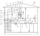
以下、図1〜図4に基づいて、本発明の実施形態である全館空調システム100について説明する。図1〜図3に示すように、全館空調システム100は二階建ての建物Hに施工されている。建物H内の二階部分の非居室空間に空調室1が設けられ、一階の天井面7と二階の床面8との間に階間空間6が設けられている。空調室1及び階間空間6は何れも気密・断熱構造となっている。気密・断熱構造の具体的構成は限定しないが、例えば、発泡ボード、吹き付け発泡、グラスウールなど、任意の手段が使用可能である。
Hereinafter, the entire building
空調室1内には空調機2並びに換気装置である全熱交換器3が配置され、空調室1内は水平な仕切り板10によって二つの領域1a,1bに区画され、空調機2は二つの領域1a,1bを跨いだ状態に配置されている。空調機2は上部に吸込口2aがあり、下部に吹出口2bがあるので、空調機1の高さ方向の中間付近に仕切り板10が位置するように配置されている。これにより、空調室1の領域1a(上部空間)に空調機2の吸込口2aが位置し、領域1b(下部空間)に空調機2の吹出口2bが位置している。
An
従って、仕切り板10の上方に位置する一方の領域1a(上部空間)は建物H内の空気と外気とを空調機2の吸込側に取り込む領域となり、仕切り板10の下方に位置する他方の領域1b(下部空間)は建物H内の空気と外気とを混合して空調機2にて温度調整された空調空気を吹き出す領域となっている。
Therefore, one
本実施形態の全館空調システム100においては、換気装置である全熱交換器3は空調室1内に設置されているが、これに限定するものではないので、建物H内の他の場所に設置することもできる。
In the whole building air-
前述したように、空調室1は気密断熱構造を成しているが、仕切り板10自体も断熱性があるものが好適である。なお、仕切り板10は平板状の部材に限定しないので、仕切り板10の代わりにシート部材を用いることも可能である。シート部材を使用すれば、空調機2のメンテナンスの際にシート材を捲ることが可能となるので、メンテナンス作業が容易となる。また、シート部材のほかに、アコーデオンカーテンのように開閉可能な蛇腹状の部材を使用することもできる。
As described above, the
また、空調室1を区画する隔壁12において上方の領域1aに面する部分には建物H内の空気の吸込口4が設けられ、隔壁12において下方の領域1bに面する部分には建物H内の空気を空調機2の吹出口2b側の領域1bに取り込むバイパス手段であるファン11が配置されている。
Further, an
空調室1の下方部分の、二階の床面Fと連続する部分には建物H内への空調空気の給気口5が設けられ、この給気口5は建物H内の階間空間6に連通している。建物H内の階間空間6を形成する一階の天井面7、二階の床面8並びに隔壁13には建物H内へ空調空気を供給する複数の吹出口9が配置されている。複数の吹出口9はそれぞれブースターファン9aを備えている。
An
建物Hの外壁Wには、排気口14並びに吸気口15が設けられている。排気口14はダクト16を経由して全熱交換器3に接続され、吸気口15はダクト17を経由して全熱交換器3に接続されている。一階の天井面7並びに二階の床面8にはそれぞれ吸込口18が設けられ、これらの吸込口18はダクト19を経由して全熱交換器3に接続されている。
An
図1に示す全館空調システム100を通常運転モードで稼働させると、空調機2並びに全熱交換器3が運転する。これにより、空調機2は、空調室1の領域1a内の空気(建物H内の空気+熱交換後の外気)を吸い込んで温度調節し、温度調節された空調空気を空調室1の領域1b内へ吹き出す。空調室1の領域1b内へ吹き出された空調空気は給気口5を通過して階間空間6内へ流入し、階間空間6内を拡散、流動していき、一階の天井面7の吹出口9並びに二階の床面8の吹出口9、吹き抜け部の隔壁13の吹出口9からそれぞれ建物H内へ送り込まれる。吹出口9からの空調空気の吹出量が不足するときはブースターファン9aを運転させることによって対応することができる。
When the entire building
一方、建物H内の空気は、一階の天井面7の吸込口18並びに二階の床面8の吸込口18からダクト19を経由して全熱交換器3に吸い込まれ、吸気口15からダクト17を経由して全熱交換器3に吸い込まれた外気との間で熱交換され、ダクト16を経由して排気口14から建物H外へ排出される。
On the other hand, the air in the building H is sucked into the
吸気口15からダクト17を経由して全熱交換器3に吸い込まれた外気は、吸込口18からダクト19を経由して全熱交換器3に吸い込まれた建物H内の空気との間で熱交換され、ダクト20を経由して、空調室1の領域1a内へ送り込まれる。
The outside air sucked into the
空調室1の領域1a内においては、ダクト20を経由して送り込まれた熱交換後の外気と、吸込口4を経由して領域1a内へ流入した建物H内の空気とが混じり合って空調機2の吸込口2aから吸い込まれ、空調機2内で温度調節されて空調空気となり、空調機2の吹出口2bから空調室1の領域1b内へ吹き出される。
In the
図2,図3は、それぞれ建物H内の一階部分、二階部分における空気の流れを示している。図2,図3において実線矢印はSA(Supply Air:空調機2から供給される調和空気)の流れを示し、破線矢印はRA(Return Air:建物H内から回収される空気)の流れを示している。 2 and 3 show the air flow in the first floor and the second floor in the building H, respectively. In FIGS. 2 and 3, the solid line arrow indicates the flow of SA (Supple Air: conditioned air supplied from the air conditioner 2), and the broken line arrow indicates the flow of RA (Return Air: air recovered from the inside of the building H). ing.
また、図2,図3において、一階の脱衣室22と二階のウォークインクローゼット29とはパスグリル21を介して連通され、トイレ24には換気扇23が配置されている。また、図3中の符号25は室内空気を換気扇に導入する吸込口を示し、符号26はパスグリルを示している。
Further, in FIGS. 2 and 3, the
前述したように、全館空調システム100においては、建物H内の空気と外気とを空調室1内に取り入れ、空調機2にて温度調節した空調空気を、階間空間6を経由して建物H内へ供給することができる。従って、建物H内の階間空間6が空調空気の供給流路となり、建物H内に空調空気供給用のダクトを配置する必要がなくなるので、ダクト施工やメンテナンスが不要となり、空調システムの構成を簡素化することができる。
As described above, in the whole building air-
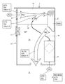
次に、図4に基づいて、全館空調システム100を除湿運転モードで稼働させた場合について説明する。図4に示すように、全館空調システム100を除湿運転モードで稼働させる場合、空調機2並びに全熱交換器3を運転させるとともにファン11も運転させる。前述したように、ファン11は建物H内の空気を空調機2の吹出口2b側の領域1bに取り込むバイパス手段である。
Next, a case where the entire building
空調機2、全熱交換器3並びにファン11が運転すると、空調機2は、空調室1の領域1a(上部空間)内の空気(建物H内の空気+熱交換後の外気)を吸い込んで温度調節し、温度調節された空調空気を吹出口2bから空調室1の領域1b(下部空間)内へ吹き出す。また、ファン11は建物H内の空気を吸い込んで、空調機2の吹出口2b側の領域1b(下部空間)内へ吹き出す。
When the
空調室1の領域1b内においては、空調機2の吹出口2bから吹き出す空調空気と、ファン11から吹き出す建物H内の空気とが混じり合い、建物H内の空気と混じり合った空調空気が給気口5から階間空間6内へ流入し、階間空間6内を拡散、流動していき、一階の天井面7の吹出口9、二階の床面8の吹出口9並びに吹き抜け部壁面の吹出口9からそれぞれ建物H内へ送り込まれる。吹出口9からの空調空気の吹出量が不足するときはブースターファン9aを運転させることによって対応することができる。
In the
一方、建物H内の空気は、一階の天井面7並びに二階の床面8の吸込口18からダクト19を経由して全熱交換器3に吸い込まれ、吸気口15からダクト17を経由して全熱交換器3に吸い込まれた外気との間で熱交換され、ダクト16を経由して排気口14から建物H外へ排出される。
On the other hand, the air in the building H is sucked into the
一方、吸気口15からダクト17を経由して全熱交換器3に吸い込まれた外気は、吸込口18からダクト19を経由して全熱交換器3に吸い込まれた建物H内の空気との間で熱交換され、ダクト20を経由して、空調室1の領域1a内へ送り込まれる。
On the other hand, the outside air sucked into the
空調室1の領域1a内においては、ダクト20を経由して送り込まれた熱交換後の外気と、吸込口4を経由して領域1a内へ流入した建物H内の空気とが混じり合い、空調機2の吸込口2aから吸い込まれ、空調機2内で温度調節されて空調空気となり、空調室1の領域1b内へ吹き出される。
In the
空調室1の領域1b内においては、空調機2の吹出口2bから吹き出す空調空気と、ファン11から吹き出す建物H内の空気とが混じり合い、前述したように、建物H内の空気と混じり合った空調空気が給気口5から階間空間6内へ流入する。
In the
次に、図5〜図7に基づいて、全館空調システム100における通常運転と除湿運転との相違点などについて説明する。なお、図5,図6中に示すアルファベット符号の意味は以下の通りである。
Next, the difference between the normal operation and the dehumidifying operation in the whole building
SA(Supply Air:給気)空調機2から供給される調和空気
RA(Return Air:還気)建物H内から回収される空気
OA(Outside Air:外気)建物H外から建物H内へ取り込まれる空気
BP(ByPass:副還気)建物H内からファン11により回収される空気
TSA(Total Supply Air:全給気)領域1b内で混合され給気口5から階間空間6へ供給される調和空気
SA (Supply Air) Harmonized air supplied from the
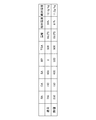
また、図7中のアルファベット符号「RA」,「OA」,「SA」,「BP」,「TSA」の下欄に示す数字は空気の流量(m3/h)を示し、「温度」は吹出口9から吹き出す空気の温度(℃)を示し、「相対湿度」の下欄に示す数字は相対湿度(%)を示し、「絶対湿度」の下欄に示す数字は吹出口9から吹き出す空気の絶対湿度(g/kg’)を示している。なお、「相対湿度」は{(実際の水蒸気量)/(飽和水蒸気量)}×100(%)を示し、「絶対湿度」は湿り空気に含まれる水蒸気の質量を指し、乾き空気1kgに対する量(g/kg’)を示している。
The numbers shown in the lower columns of the alphabetic symbols "RA", "OA", "SA", "BP", and "TSA" in FIG. 7 indicate the air flow rate (m 3 / h), and "temperature" is The temperature (° C) of the air blown out from the
全館空調システム100が通常運転しているときは、図1,図5に示すように、空調機2の吹出口2bから領域1b内へ吹き出す空調空気が、そのまま給気口5を通過して階間空間6内へ流入し、建物H内の空調に供される。これに対し、全館空調システム100が除湿運転しているときは、図4,図6に示すように、空調機2の吹出口2bから領域1b内へ吹き出す空調空気と、ファン11から領域1b内へ吹き出す建物H内の空気と、が領域1b内で混合され、建物H内の空気と混じり合った空調空気が給気口5を通過して階間空間6内へ流入し、建物H内の空調に供される。
When the entire building
即ち、全館空調システム100が通常運転しているときは、図5に示すように、空調機2で温度・湿度調節された空調空気SAがそのまま建物H内の空調に供されるのに対し、全館空調システム100が除湿運転しているときは、図6に示すように、空調機2で温度湿度調節された空調空気SAと、ファン11から取り込まれた建物H内の空気BPと、が混じり合った空調空気TSAが建物H内の空調に供される点において相違している。
That is, when the entire building
図7中の「温度」、「相対湿度」並びに「絶対湿度」の下欄の数字を見ると、全館空調システム100が通常運転しているときに吹出口9から吹き出す空気については温度18.2℃、相対湿度95%、絶対湿度12,7g/kg’であるのに対し、全館空調システム100が除湿運転しているときに吹出口9から吹き出す空気については温度18.0℃、相対湿度87%、絶対湿度11.2g/kg’となっている。
Looking at the numbers in the lower columns of "Temperature", "Relative Humidity" and "Absolute Humidity" in FIG. 7, the temperature of the air blown out from the
従って、全館空調システム100が通常運転しているときと、除湿運転しているときとを比較すると、1時間で1.6L/hの除湿能力の差が生じ、除湿運転しているときは通常運転しているときより除湿能力が高いことが分かる。
Therefore, when comparing the time when the entire building
次に、図8,図9に基づいて、本発明に係る全館空調システムを構成する空調室に関するその他の実施形態について説明する。なお、図8,図9に示す空調室1X,1Yの構成部分において図1に示す全館空調システム100の構成部分と共通する部分については図1中の符号と同符号を付して説明を省略する。
Next, other embodiments relating to the air-conditioning room constituting the whole building air-conditioning system according to the present invention will be described with reference to FIGS. 8 and 9. The parts of the air-
図8に示す空調室1Xにおいては、換気装置として空調室1X内に配置されている全熱交換器3Xが、エレメントボックス3a、ファンボックス3b及び接続チャンバー3cによって構成されている。接続チャンバー3cは空調室1Xの床面27上に配置され、この接続チャンバー3c上にエレメントボックス3a及びファンボックス3bが並列して配置され、エレメントボックス3aとファンボックス3bとが接続チャンバー3cによって接続されている。
In the air-
ダクト17,19を経由してエレメントボックス3aに吸い込まれた「OA」、「RA」は、エレメントボックス3aを通過する過程で熱交換されて接続チャンバー3c内へ流入し、接続チャンバー3c内でUターンするように流動方向を変えて、ファンボックス3bに吸い込まれ、「OA」はダクト20を経由して領域1a内へ吹き出され、「RA」はダクト16を経由して排気口14から建物H外へ「EA」として排出される。
The "OA" and "RA" sucked into the
図8に示す空調室1Xは、全熱交換器3Xの高さ寸法を抑えることができるので、スペース的に有利であり、接続チャンバー3cを底面にして空調室1X内の床面27上に設置できるので、設置作業も容易である。
The air-
図9に示す空調室1Yにおいては、換気装置として空調室1Y内に配置されている全熱交換器3Yが、エレメントボックス3a、ファンボックス3b及び接続チャンバー3dによって構成されている。空調室1Yの床面28上にエレメントボックス3a及び接続チャンバー3dが並列して配置され、接続チャンバー3d上にファンボックス3bが配置され、エレメントボックス3aとファンボックス3bとが接続チャンバー3cによって接続されている。
In the air-
ダクト17,19を経由してエレメントボックス3aに吸い込まれた「OA」、「RA」は、エレメントボックス3aを通過する過程で熱交換されて接続チャンバー3d内へ流入し、接続チャンバー3d内で流動方向を90度変えて、ファンボックス3bに吸い込まれ、「OA」はダクト20を経由して領域1a内へ吹き出され、「RA」はダクト16を経由して排気口14から建物H外へ「EA」として排出される。
The "OA" and "RA" sucked into the
図9に示す空調室1Yは、全熱交換器3Yの高さ寸法を抑えることができるので、スペース的に有利であり、エレメントボックス3a及び接続チャンバー3dを底面にして空調室1Y内の床面28上に設置できるので、設置作業も容易である。また、全熱交換器3Yは、接続チャンバー3d内においてがUターンしないため(流路が180度曲げではなく90度曲げであるため)、流路内の圧力損失を低くすることができる。
The air-
次に、図10に基づいて、本発明のその他の実施形態である全館空調システム200について説明する。図10に示すように、全館空調システム200においては、建物H内の居室空間31,32に、それぞれ空調用の放射パネル30が配置されている。その他の部分は図1に示す全館空調システム100と同様である。
Next, the whole building
放射パネル30は、起立姿勢で並列状に配管された複数の管状体33を備え、これらの管状体33内に、夏期は冷水を循環させ、冬期は温水を循環させることにより、複数の管状体33から輻射波を放射させ、居室空間31,32内の空調を行うものである。
The radiating
居室空間31,32内に放射パネル30を配置すれば、放射パネル30による心地良い放射空調を実現することができる。また、空調室1内に配置された空調機2から供給される空調空気により、建物H内(特に居室空間31,32内)の温度調節の補助及び湿度コントロールを行うことができるので、快適性がさらに向上する。
If the
さらに、除湿運転を行うことにより放射パネル30の結露発生を防止することができるので、結露水を処理するドレンパンや排水用配管の設置が不要となり、シンプルな空調システムにすることができ、コスト低減を図ることもできる。
Further, since the dehumidifying operation can prevent the occurrence of dew condensation on the
なお、図1〜図10に基づいて説明した全館空調システム100,200並びに空調室1X,1Yなどは、本発明に係る全館空調システムを例示するものであり、本発明に係る全館空調システムは、前述した全館空調システム100,200並びに空調室1X,1Yなどに限定されない。
The whole building
本発明に係る全館空調システムは、各種建物内の空調システムとして、建築業、建設業などの産業分野において広く利用することができる。 The whole building air conditioning system according to the present invention can be widely used in industrial fields such as the construction industry and the construction industry as an air conditioning system in various buildings.
1,1X,1Y 空調室
1a 領域(上部空間)
1b 領域(下部空間)
2 空調機
2a,4,18 吸込口
2b,9 吹出口
3,3X,3Y 全熱交換器(換気装置)
3a エレメントボックス
3b ファンボックス
3c,3d 接続チャンバー
5 給気口
6 階間空間
7 天井面
8,27,28 床面
10 仕切り板
11 ファン
12,13 隔壁
14 排気口
15 吸気口
16,17,19,20 ダクト
18,25 吸込口
21,26 パスグリル
22 脱衣室
23 換気扇
24 トイレ
29 ウォークインクローゼット
30 放射パネル
31,32 居室空間
33 管状体
100,200 全館空調システム
H 建物
W 外壁
1,1X, 1Y
1b area (lower space)
2
Claims (8)
前記空調室内に配置された空調機並びに前記建物内に設置された換気装置と、
前記空調室の一部に設けられた前記建物内の空気の吸込口並びに前記建物内への空調空気の給気口と、を備え、
前記空調空気の給気口が前記建物内の階間空間に連通し、
前記建物内の階間空間を形成する天井面、床面若しくは吹き抜け部壁面に、前記建物内へ空調空気を供給する吹出口を有し、
前記建物内の空気と外気とを前記空調室内に取り入れ、前記空調機にて温度及び湿度を調節した空調空気を、前記階間空間を経由して前記建物内へ供給することを特徴とする全館空調システム。 An air-conditioning room provided in a non-living space (excluding the attic space and the underfloor space) in the building,
An air conditioner installed in the air conditioning room and a ventilation device installed in the building,
It is provided with an air suction port in the building provided in a part of the air conditioning room and an air supply port for air conditioning air in the building.
The air supply port of the conditioned air communicates with the interfloor space in the building,
The ceiling surface, floor surface, or wall surface of the atrium that forms the interfloor space in the building has an air outlet that supplies conditioned air into the building.
The entire building is characterized in that the air inside the building and the outside air are taken into the air-conditioning room, and the air-conditioned air whose temperature and humidity are adjusted by the air conditioner is supplied into the building via the inter-floor space. Air conditioning system.
前記空調室内に配置された空調機並びに前記建物内に設置された換気装置と、
前記空調室の一部に設けられた前記建物内の空気の吸込口並びに前記建物内への空調空気の給気口と、を備え、
前記空調空気の給気口が前記建物内の天井裏空間若しくは床下空間のうちの少なくとも一方に連通し、
前記建物内の天井面若しくは床面の何れか一方に空調空気を前記建物内に供給する吹出口を有し、
前記建物内の空気と外気とを前記空調室内に取り入れ、前記空調機にて温度及び湿度を調節した空調空気を、前記天井裏空間若しくは前記床下空間のうちの少なくとも一方を経由して前記建物内に供給することを特徴とする全館空調システム。 An air-conditioning room provided in a non-living space (excluding the attic space and the underfloor space) in the building,
An air conditioner installed in the air conditioning room and a ventilation device installed in the building,
It is provided with an air suction port in the building provided in a part of the air conditioning room and an air supply port for air conditioning air in the building.
The air-conditioning air supply port communicates with at least one of the attic space and the underfloor space in the building.
It has an air outlet that supplies conditioned air into the building on either the ceiling surface or the floor surface in the building.
The air inside the building and the outside air are taken into the air conditioning room, and the air conditioning air whose temperature and humidity are adjusted by the air conditioner is passed through at least one of the ceiling space and the underfloor space inside the building. The entire building air conditioning system is characterized by supplying to.
一方の領域を、前記建物内の空気と外気とを前記空調機の吸込側に取り込む領域とし、
他方の領域を、前記建物内の空気と外気とを混合して空調機にて温度調整した空調空気を吹き出す領域とし、さらに、前記他方の領域に、前記建物内の空気を前記空調機の吹出側に取り込むバイパス手段を設けた請求項1または2記載の全館空調システム。 The air conditioning chamber is divided into two areas, and the air conditioner is arranged so as to straddle the two areas.
One area is defined as an area where the air inside the building and the outside air are taken into the suction side of the air conditioner.
The other region is a region where the air inside the building and the outside air are mixed and air-conditioned air whose temperature is adjusted by an air conditioner is blown out, and further, the air inside the building is blown out by the air conditioner to the other region. The whole building air-conditioning system according to claim 1 or 2, which is provided with a bypass means for taking in on the side.
Priority Applications (1)
| Application Number | Priority Date | Filing Date | Title |
|---|---|---|---|
| JP2020077406A JP7490438B2 (en) | 2020-04-24 | 2020-04-24 | Whole building air conditioning system |
Applications Claiming Priority (1)
| Application Number | Priority Date | Filing Date | Title |
|---|---|---|---|
| JP2020077406A JP7490438B2 (en) | 2020-04-24 | 2020-04-24 | Whole building air conditioning system |
Publications (2)
| Publication Number | Publication Date |
|---|---|
| JP2021173473A true JP2021173473A (en) | 2021-11-01 |
| JP7490438B2 JP7490438B2 (en) | 2024-05-27 |
Family
ID=78281482
Family Applications (1)
| Application Number | Title | Priority Date | Filing Date |
|---|---|---|---|
| JP2020077406A Active JP7490438B2 (en) | 2020-04-24 | 2020-04-24 | Whole building air conditioning system |
Country Status (1)
| Country | Link |
|---|---|
| JP (1) | JP7490438B2 (en) |
Cited By (3)
| Publication number | Priority date | Publication date | Assignee | Title |
|---|---|---|---|---|
| CN114183867A (en) * | 2021-11-24 | 2022-03-15 | 中铁第五勘察设计院集团有限公司 | Air-conditioning ventilation system of subway underground station platform |
| JP2023082652A (en) * | 2021-12-02 | 2023-06-14 | 株式会社Fhアライアンス | air conditioning ventilation system |
| JP2024087445A (en) * | 2022-12-19 | 2024-07-01 | パナソニックホームズ株式会社 | Building and air conditioning system |
Citations (6)
| Publication number | Priority date | Publication date | Assignee | Title |
|---|---|---|---|---|
| JPH02242032A (en) * | 1989-03-16 | 1990-09-26 | Misawa Homes Co Ltd | Ductless air conditioning system for building |
| US5353601A (en) * | 1993-02-16 | 1994-10-11 | Palmer Gerald R | Structural cooling systems and methods |
| JP2015055433A (en) * | 2013-09-13 | 2015-03-23 | 株式会社 テスク資材販売 | Air conditioning system |
| JP2016080311A (en) * | 2014-10-21 | 2016-05-16 | トヨタホーム株式会社 | Ventilation structure of building |
| JP2017150704A (en) * | 2016-02-23 | 2017-08-31 | パナホーム株式会社 | Ventilation air-conditioning unit |
| JP2019105383A (en) * | 2017-12-11 | 2019-06-27 | 株式会社Fhアライアンス | Air conditioning unit |
-
2020
- 2020-04-24 JP JP2020077406A patent/JP7490438B2/en active Active
Patent Citations (6)
| Publication number | Priority date | Publication date | Assignee | Title |
|---|---|---|---|---|
| JPH02242032A (en) * | 1989-03-16 | 1990-09-26 | Misawa Homes Co Ltd | Ductless air conditioning system for building |
| US5353601A (en) * | 1993-02-16 | 1994-10-11 | Palmer Gerald R | Structural cooling systems and methods |
| JP2015055433A (en) * | 2013-09-13 | 2015-03-23 | 株式会社 テスク資材販売 | Air conditioning system |
| JP2016080311A (en) * | 2014-10-21 | 2016-05-16 | トヨタホーム株式会社 | Ventilation structure of building |
| JP2017150704A (en) * | 2016-02-23 | 2017-08-31 | パナホーム株式会社 | Ventilation air-conditioning unit |
| JP2019105383A (en) * | 2017-12-11 | 2019-06-27 | 株式会社Fhアライアンス | Air conditioning unit |
Cited By (4)
| Publication number | Priority date | Publication date | Assignee | Title |
|---|---|---|---|---|
| CN114183867A (en) * | 2021-11-24 | 2022-03-15 | 中铁第五勘察设计院集团有限公司 | Air-conditioning ventilation system of subway underground station platform |
| JP2023082652A (en) * | 2021-12-02 | 2023-06-14 | 株式会社Fhアライアンス | air conditioning ventilation system |
| JP7432956B2 (en) | 2021-12-02 | 2024-02-19 | 株式会社Fhアライアンス | air conditioning ventilation system |
| JP2024087445A (en) * | 2022-12-19 | 2024-07-01 | パナソニックホームズ株式会社 | Building and air conditioning system |
Also Published As
| Publication number | Publication date |
|---|---|
| JP7490438B2 (en) | 2024-05-27 |
Similar Documents
| Publication | Publication Date | Title |
|---|---|---|
| JP2009276041A (en) | Air-conditioning ventilation system for building | |
| JP7490438B2 (en) | Whole building air conditioning system | |
| JP5504015B2 (en) | Ventilation air conditioning system and building | |
| JP6845592B1 (en) | Ventilation system | |
| JP6211675B1 (en) | Whole building air conditioning system | |
| JP5530282B2 (en) | Ventilation air conditioning system and building | |
| JP7387255B2 (en) | Whole building air conditioning system | |
| JPH10220807A (en) | Air conditioning system using low floor double floor | |
| JP7093067B2 (en) | Air conditioning system and house | |
| JP2010032099A (en) | Ventilation system | |
| JP7358122B2 (en) | Whole building air conditioning system | |
| JP2003269767A (en) | Ventilation and air conditioning systems and buildings | |
| JPH09257275A (en) | Cooling/heating and ventilating system for building | |
| JP7393884B2 (en) | air conditioning system | |
| JPH1144435A (en) | Air circulation type air conditioning floor heating system house | |
| JPH04106333A (en) | Integral central type air conditioner system | |
| JP3077026B2 (en) | House air conditioning system | |
| JPH0719525A (en) | Underfloor blowout air conditioner | |
| JPH11218342A (en) | Air conditioner system for housing and method for air conditioning | |
| JP2006162180A (en) | Air conditioner with ventilation function and ventilation air conditioner throughout the building | |
| JP7214457B2 (en) | Whole building air conditioning system | |
| JP7845699B2 (en) | Air conditioning system | |
| JP2019039602A (en) | Air conditioning system | |
| JPH06323570A (en) | Air-conditioning method and its equipment in a multi-story room | |
| JPH06300350A (en) | Floor structure, air conditioner and floor heater |
Legal Events
| Date | Code | Title | Description |
|---|---|---|---|
| A621 | Written request for application examination |
Free format text: JAPANESE INTERMEDIATE CODE: A621 Effective date: 20230324 |
|
| A977 | Report on retrieval |
Free format text: JAPANESE INTERMEDIATE CODE: A971007 Effective date: 20231219 |
|
| A131 | Notification of reasons for refusal |
Free format text: JAPANESE INTERMEDIATE CODE: A131 Effective date: 20240109 |
|
| RD03 | Notification of appointment of power of attorney |
Free format text: JAPANESE INTERMEDIATE CODE: A7423 Effective date: 20240201 |
|
| A521 | Request for written amendment filed |
Free format text: JAPANESE INTERMEDIATE CODE: A523 Effective date: 20240209 |
|
| TRDD | Decision of grant or rejection written | ||
| A01 | Written decision to grant a patent or to grant a registration (utility model) |
Free format text: JAPANESE INTERMEDIATE CODE: A01 Effective date: 20240507 |
|
| A61 | First payment of annual fees (during grant procedure) |
Free format text: JAPANESE INTERMEDIATE CODE: A61 Effective date: 20240515 |
|
| R150 | Certificate of patent or registration of utility model |
Ref document number: 7490438 Country of ref document: JP Free format text: JAPANESE INTERMEDIATE CODE: R150 |