JP2021517543A - Waste container with bag handling assembly - Google Patents
Waste container with bag handling assembly Download PDFInfo
- Publication number
- JP2021517543A JP2021517543A JP2020549607A JP2020549607A JP2021517543A JP 2021517543 A JP2021517543 A JP 2021517543A JP 2020549607 A JP2020549607 A JP 2020549607A JP 2020549607 A JP2020549607 A JP 2020549607A JP 2021517543 A JP2021517543 A JP 2021517543A
- Authority
- JP
- Japan
- Prior art keywords
- bag
- cage
- bag support
- wall
- container
- Prior art date
- Legal status (The legal status is an assumption and is not a legal conclusion. Google has not performed a legal analysis and makes no representation as to the accuracy of the status listed.)
- Pending
Links
Images


Classifications
-
- B—PERFORMING OPERATIONS; TRANSPORTING
- B65—CONVEYING; PACKING; STORING; HANDLING THIN OR FILAMENTARY MATERIAL
- B65F—GATHERING OR REMOVAL OF DOMESTIC OR LIKE REFUSE
- B65F1/00—Refuse receptacles; Accessories therefor
- B65F1/04—Refuse receptacles; Accessories therefor with removable inserts
- B65F1/06—Refuse receptacles; Accessories therefor with removable inserts with flexible inserts, e.g. bags or sacks
-
- B—PERFORMING OPERATIONS; TRANSPORTING
- B65—CONVEYING; PACKING; STORING; HANDLING THIN OR FILAMENTARY MATERIAL
- B65B—MACHINES, APPARATUS OR DEVICES FOR, OR METHODS OF, PACKAGING ARTICLES OR MATERIALS; UNPACKING
- B65B67/00—Apparatus or devices facilitating manual packaging operations; Sack holders
- B65B67/12—Sack holders, i.e. stands or frames with means for supporting sacks in the open condition to facilitate filling with articles or materials
- B65B67/1222—Sack holders, i.e. stands or frames with means for supporting sacks in the open condition to facilitate filling with articles or materials characterised by means for suspending sacks, e.g. pedal- operated
- B65B67/1233—Clamping or holding means
-
- B—PERFORMING OPERATIONS; TRANSPORTING
- B65—CONVEYING; PACKING; STORING; HANDLING THIN OR FILAMENTARY MATERIAL
- B65B—MACHINES, APPARATUS OR DEVICES FOR, OR METHODS OF, PACKAGING ARTICLES OR MATERIALS; UNPACKING
- B65B67/00—Apparatus or devices facilitating manual packaging operations; Sack holders
- B65B67/12—Sack holders, i.e. stands or frames with means for supporting sacks in the open condition to facilitate filling with articles or materials
- B65B67/1244—Sack holders, i.e. stands or frames with means for supporting sacks in the open condition to facilitate filling with articles or materials characterised by mechanisms for temporarily closing the mouth of the sack, e.g. pedal-operated
- B65B67/125—Sack holders, i.e. stands or frames with means for supporting sacks in the open condition to facilitate filling with articles or materials characterised by mechanisms for temporarily closing the mouth of the sack, e.g. pedal-operated comprising resilient closing elements, e.g. inserts, cooperating with the mouth of the sack
-
- B—PERFORMING OPERATIONS; TRANSPORTING
- B65—CONVEYING; PACKING; STORING; HANDLING THIN OR FILAMENTARY MATERIAL
- B65F—GATHERING OR REMOVAL OF DOMESTIC OR LIKE REFUSE
- B65F1/00—Refuse receptacles; Accessories therefor
- B65F1/14—Other constructional features; Accessories
- B65F1/16—Lids or covers
- B65F1/1607—Lids or covers with filling openings
-
- B—PERFORMING OPERATIONS; TRANSPORTING
- B65—CONVEYING; PACKING; STORING; HANDLING THIN OR FILAMENTARY MATERIAL
- B65B—MACHINES, APPARATUS OR DEVICES FOR, OR METHODS OF, PACKAGING ARTICLES OR MATERIALS; UNPACKING
- B65B67/00—Apparatus or devices facilitating manual packaging operations; Sack holders
- B65B67/12—Sack holders, i.e. stands or frames with means for supporting sacks in the open condition to facilitate filling with articles or materials
- B65B2067/1261—Holders with lids
-
- B—PERFORMING OPERATIONS; TRANSPORTING
- B65—CONVEYING; PACKING; STORING; HANDLING THIN OR FILAMENTARY MATERIAL
- B65F—GATHERING OR REMOVAL OF DOMESTIC OR LIKE REFUSE
- B65F1/00—Refuse receptacles; Accessories therefor
- B65F1/14—Other constructional features; Accessories
- B65F2001/1653—Constructional features of lids or covers
- B65F2001/1676—Constructional features of lids or covers relating to means for sealing the lid or cover, e.g. against escaping odors
-
- B—PERFORMING OPERATIONS; TRANSPORTING
- B65—CONVEYING; PACKING; STORING; HANDLING THIN OR FILAMENTARY MATERIAL
- B65F—GATHERING OR REMOVAL OF DOMESTIC OR LIKE REFUSE
- B65F2210/00—Equipment of refuse receptacles
- B65F2210/129—Deodorizing means
Landscapes
- Engineering & Computer Science (AREA)
- Mechanical Engineering (AREA)
- Refuse Receptacles (AREA)
Abstract
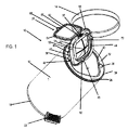
バッグ(16)を受け入れ可能な内部空間を規定するベース部(18)及び外壁(12)を含む容器(10)。バッグ取り扱いアセンブリ(26)は、壁(12)に結合され、且つ壁(12)に接続された保持器(28)と、保持器(28)及びバッグ支持体(44)上の協働式ヒンジ構成要素(36、46)によって保持器(28)に回動可能に結合されたバッグ支持体(44)と、保持器(28)に対するバッグ支持体(44)の回動可能な結合から独立して、バッグ支持体(44)及びクロージャ構成要素(60)上の協働式ヒンジ構成要素(58、62)によってバッグ支持体(44)に回動可能に結合されたクロージャ構成要素(60)とを含む。容器(10)は、2つの別個の独立した回動可能な取り付け機構を含み、その一方は、バッグ(16)をクロージャ構成要素(60)とバッグ支持体(44)との間に固定する役割を果たし、及びその他方は、バッグを挿入及び除去するための容器(10)の内側へのより良好なアクセスを可能にする役割を果たす。【選択図】図1A container (10) including a base portion (18) and an outer wall (12) that define an internal space that can accommodate the bag (16). The bag handling assembly (26) is coupled to the wall (12) and connected to the wall (12) with a cage (28) and a collaborative hinge on the cage (28) and the bag support (44). Independent of the rotatable coupling of the bag support (44) to the cage (28) by the components (36, 46) and the bag support (44) to the cage (28). With the closure component (60) rotatably coupled to the bag support (44) by the collaborative hinge components (58, 62) on the bag support (44) and closure component (60). including. The container (10) includes two separate, independent, rotatable mounting mechanisms, one of which serves to secure the bag (16) between the closure component (60) and the bag support (44). And others serve to allow better access to the inside of the container (10) for inserting and removing the bag. [Selection diagram] Fig. 1
Description
本発明は、概して、猫用トイレ砂、病院、診療所、在宅医療要員及び施設、養護施設、バイオハザード研究所からの医療廃棄物、おむつ、一般家庭ごみ、使い捨て商品などを含むが、これらに限定されないあらゆる種類の廃棄物に使用することができる廃棄物処分装置であって、廃棄物が挿入されるときに廃棄物受け器にバッグが落ちないようにバッグを確実に保持又は捕捉する構造を含み得る廃棄物処分装置に関する。 The present invention generally includes cat toilet sand, hospitals, clinics, home medical personnel and facilities, nursing homes, medical waste from biohazard laboratories, diapers, general household waste, disposable products, and the like. A waste disposal device that can be used for all types of waste, not limited to, with a structure that securely holds or captures the bag so that it does not fall into the waste receiver when the waste is inserted. Concerning waste disposal equipment that can be included.
廃棄物処分装置は、病院、診療所、厨房及び他の家庭の場所並びに廃棄物が生じ、且つ衛生的な方法で処分する必要がある他の場所で一般的である。廃棄物処分装置は、家庭ごみ、猫用トイレ砂及び他のペットごみを処分するためにもよく使用される。廃棄物が臭気を発する場合、廃棄物処分装置は、廃棄物から発生する臭気も閉じ込めるべきである。 Waste disposal equipment is common in hospitals, clinics, kitchens and other home locations as well as other locations where waste is generated and needs to be disposed of in a hygienic manner. Waste disposal equipment is also commonly used to dispose of household waste, litter box sand and other pet waste. If the waste emits an odor, the waste disposal device should also contain the odor generated from the waste.
いくつかの廃棄物処分装置は、チューブを分配するディスペンサーを含み、したがってチューブ状コア又はカートリッジが置かれ、連続した長さの柔軟で実質的に弾力性のないプラスチックチューブを収容する内部リング形状フランジを含む。結び目が一端で結ばれ、連続したチューブが円筒容器の底まで引き下げられて、バッグが満杯になるまでおむつを次々と挿入するためのバッグを形成する。満杯になったら、内蔵のブレードでバッグの上部を切り、その後の除去のために開放領域で結び目を作る。この手順 − 結び目を作り − バッグを満たし − バッグを除去するなど − をもう一度繰り返す。キャニスタのバッグの長さがなくなったら、キャニスタを交換する。キャニスタは、高価であり、定期的に交換する必要がある。 Some waste disposal devices include an internal ring-shaped flange that contains a dispenser that distributes the tubing, thus containing a tubing core or cartridge that accommodates a continuous length of flexible, virtually inelastic plastic tubing. including. The knot is tied at one end and the continuous tube is pulled down to the bottom of the cylindrical container to form a bag for inserting diapers one after another until the bag is full. When full, cut the top of the bag with a built-in blade and tie a knot in the open area for subsequent removal. Repeat this procedure-tie a knot-fill the bag-remove the bag, and so on. Replace the canister when the canister bag is no longer long. Canisters are expensive and need to be replaced on a regular basis.
別の処分装置は、一端で密封され、開放端で折り畳み式プラスチックヘッダーに溶接されている単回使用バッグを利用する。平らに開いたときのヘッダーは、円筒容器に確実に収まり、おむつが満杯になるにようにおむつを受け入れる。満杯になると、プラスチック製のヘッダーが折り畳まれて上部の開放領域を密封するのと同時に、取り除くのに便利な持ち手が形成される。これらのポリプロピレン製リビングヒンジヘッダーは、無駄があり、製造にコストがかかり、使い捨てバッグに溶接又は接着する必要がある。 Another disposal device utilizes a single-use bag that is sealed at one end and welded to a foldable plastic header at the open end. When opened flat, the header fits securely in a cylindrical container and accepts the diaper so that it is full. When full, the plastic header folds to seal the upper open area, while at the same time forming a convenient handle for removal. These polypropylene living hinge headers are wasteful, costly to manufacture, and need to be welded or glued to a disposable bag.
米国特許第6,612,099号、同第6,804,930号、同第6,851,251号、同第7,086,569号、同第7,114,314号、同第7,146,785号、同第7,316,100号、同第7,434,377号、同第7,503,152号、同第7,503,159号、同第7,617,659号、同第7,708,188号、同第7,712,285号、同第7,963,414号、同第8,127,519号、同第8,215,089号、同第8,235,237号、同第8,266,871号、同第8,973,774号に開示されているものを含む多数の廃棄物処分装置が存在する。さらに、革新的な廃棄物処分装置は、2008年7月14日に出願され、現在放棄されている米国特許出願公開第12/172,715号、2011年6月30日に出願され、現在放棄されている同第13/172,976号及び2011年10月11日に出願され、現在放棄されている同第13/270,697号に開示されている。 U.S. Pat. Nos. 6,612,099, 6,804,930, 6,851,251, 7,086,569, 7,114,314, 7, 146,785, 7,316,100, 7,434,377, 7,503,152, 7,503,159, 7,617,659, No. 7,708,188, No. 7,712,285, No. 7,963,414, No. 8,127,519, No. 8,215,089, No. 8,235 , 237, 8,266,871 and 8,973,774. In addition, the innovative waste disposal system was filed on July 14, 2008 and is now abandoned, US Patent Application Publication No. 12 / 172,715, filed on June 30, 2011, and is now abandoned. It is disclosed in No. 13 / 172,976, which has been filed, and No. 13 / 270, 697, which was filed on October 11, 2011 and is now abandoned.
これらの廃棄物処分装置のいくつかは、廃棄物受け入れ区画を規定するベース部と、ベース部に回動可能に接続された蓋とを含む。蓋を開けるとバッグが見え、廃棄物がバッグの開口部に挿入される。バッグは、多くの場合、廃棄物を挿入するために力を必要とする膜であって、廃棄物及び臭気の流出に対する障壁を提供しながら、廃棄物の上でバッグを閉じる役割を果たす膜を通過する。いくつかの廃棄物処分装置では、バッグは、実際には、カートリッジに収納されたアコーディオン式に折り畳まれた柔軟性チューブの長さの一部である。 Some of these waste disposal devices include a base that defines a waste receiving area and a lid that is rotatably connected to the base. When the lid is opened, the bag is visible and waste is inserted into the opening of the bag. A bag is often a membrane that requires force to insert waste, a membrane that serves to close the bag over the waste while providing a barrier against the outflow of waste and odors. pass. In some waste disposal devices, the bag is actually part of the length of an accordion-folded flexible tube housed in a cartridge.
さらに、これらの廃棄物処分装置のいくつかは、蓋の手動開放及び閉鎖を補うか又はそれに取って代わるための踏み板又はフットペダルアセンブリを含む。フットペダルアセンブリは、踏み込み式のフットペダル及びバネを含み、フットペダルを踏み込んだときの蓋の開放と、押し下げ力を除去したときの蓋の閉鎖との両方を行うように配置されている。バネは、フットペダルを踏み込むとバイアスに逆らって移動し、押し下げ力を除去すると元の状態に戻り、それにより蓋を閉鎖し、ねじり機構を回転させる。 In addition, some of these waste disposal devices include tread or foot pedal assemblies to supplement or replace the manual opening and closing of the lid. The foot pedal assembly includes a step-on foot pedal and a spring and is arranged to both open the lid when the foot pedal is depressed and close the lid when the depressing force is removed. The spring moves against the bias when the foot pedal is depressed and returns to its original state when the depressing force is removed, thereby closing the lid and rotating the torsion mechanism.
本発明による容器は、バッグを受け入れ可能な内部空間を規定する少なくとも1つの壁と、壁に結合されたバッグ取り扱いアセンブリとを含む。バッグ取り扱いアセンブリは、壁に結合された保持器と、保持器に回動可能に結合されたバッグ支持体と、保持器に対するバッグ支持体の回動可能な結合とは独立してバッグ支持体に回動可能に結合されたクロージャ構成要素とを含む。第1の取り付け構造は、バッグ支持体を保持器に回動可能に取り付ける。例えば、保持器によって規定された開口部の第1の側における保持器上のヒンジ構成要素と、バッグ支持体上の協働式ヒンジ構成要素とである。第2の取り付け構造は、クロージャ構成要素をバッグ支持体に回動可能に取り付ける。例えば、保持器によって規定された開口部の第2の側におけるバッグ支持体上の追加のヒンジ構成要素と、クロージャ構成要素上の協働式ヒンジ構成要素とである。したがって、第1及び第2の取り付け構造は、保持器によって規定された開口部の異なる側にある。この構造の利点は、両方の取り付け構造が開いた構成要素状態にあるときに干渉を防ぐことにより、容器の使用を合理化することである。 The container according to the invention includes at least one wall that defines an internal space that can accommodate the bag and a bag handling assembly coupled to the wall. The bag handling assembly is attached to the bag support independently of the wall-mounted cage, the bag support rotatably coupled to the cage, and the rotatable coupling of the bag support to the cage. Includes rotatably coupled closure components. The first mounting structure rotatably mounts the bag support to the cage. For example, a hinge component on the cage on the first side of the opening defined by the cage and a collaborative hinge component on the bag support. The second mounting structure rotatably mounts the closure component to the bag support. For example, an additional hinge component on the bag support on the second side of the opening defined by the cage and a collaborative hinge component on the closure component. Therefore, the first and second mounting structures are on different sides of the opening defined by the cage. The advantage of this structure is to streamline the use of the container by preventing interference when both mounting structures are in the open component state.
クロージャ構成要素とバッグ支持体との間にバッグを固定するために、バッグ支持体は、バッグの開放端を支持するための内壁と、内壁から離間された外壁と、内壁及び外壁間のリム部分とを含み、チャネルは、内壁及び外壁間のリム部分の上に規定される。クロージャ構成要素は、内壁に対して寸法が定められたチャネルを下側に規定し、それにより、クロージャ構成要素がバッグ支持体に対して回動されると、内壁は、このチャネルに受け入れられる。 To secure the bag between the closure component and the bag support, the bag support is provided with an inner wall for supporting the open end of the bag, an outer wall separated from the inner wall, and a rim portion between the inner wall and the outer wall. Channels are defined above the rim portion between the inner and outer walls, including. The closure component defines a channel underneath that is dimensioned relative to the inner wall so that when the closure component is rotated with respect to the bag support, the inner wall is accepted into this channel.
クロージャ構成要素をバッグ支持体に固定するために、クロージャ構成要素は、タブを含み、及びバッグ支持体は、タブと協働する可撓性の保持器を含んで、タブと保持器との係合を介したクロージャ構成要素のバッグ支持体への一時的な固定を可能にする。 To secure the closure component to the bag support, the closure component includes a tab, and the bag support includes a flexible cage that works with the tab to engage the tab with the cage. Allows temporary fixation of closure components to the bag support via a combination.
一実施形態では、バッグ支持体は、交差チャネルと、これらのチャネルからある角度における交差スリットとを任意選択的に含む膜を含み、チャネルは、バッグがその中に受け入れられることを可能にするように寸法が定められている。 In one embodiment, the bag support comprises a membrane optionally comprising crossing channels and crossing slits at an angle from these channels so that the channels allow the bag to be accepted therein. The dimensions are defined in.
本発明は、さらなる目的及びその利点と共に、添付の図面と併せて読まれる以下の記載を参照することによって最もよく理解することができる。図面では、同様の参照番号は、同様の要素を特定する。 The present invention, along with additional object and its advantages, can be best understood by reference to the following description, which is read in conjunction with the accompanying drawings. In drawings, similar reference numbers identify similar elements.
同様の参照番号が同じ又は類似の要素を指す添付の図面を参照すると、図1は、廃棄物を処分するために好ましくは使用されるが、任意の目的に使用され得る本発明による容器10を示す。容器10は、実質的に円筒形である外壁12と、容器10内に保持されたバッグ16へのアクセスが可能である第1の開位置及びバッグ16、より一般的には容器10の内部へのアクセスが阻止される第2の閉位置を有する蓋14とを含む。外壁12は、廃棄物が入れられるバッグを受け入れることができる、容器10内の内部空間又は区画を規定する少なくとも1つの壁を表す。それは、単一の壁から構成され得るか又は複数の壁を含み得る。
With reference to the accompanying drawings with similar reference numbers pointing to the same or similar elements, FIG. 1 is a
容器10はまた、図5を参照すると、外壁12が支持されるベース部18と、蓋14の開放及び閉鎖、すなわち開位置と閉位置との間の蓋14の移動を制御する蓋制御機構20とを含む。代わりに、ベース部18は、外壁12に一体化され得る。制御機構20は、フットペダル22と、フットペダル22の下方への動きを蓋14の開放運動に変換するために協働する作動ロッド24とを含み得る(図5を参照されたい)。フットペダル22は、反復的な下方への動きを可能にするために、上方位置に戻るように付勢されている。当業者は、制御機構20の作製及び使用方法を理解し、多数の異なるタイプの制御機構20が当業者に知られており、本発明で使用することができる。多くの場合、制御機構20は、容器10の外壁12及び/又はベース部18内に隠されている。
The
実際、容器10の一般的な特性は、本発明にとって重要ではなく、本発明は、本明細書に開示され且つ示されるタイプ及び形状に限定されることなく、任意のタイプ、形状及びサイズの容器で使用することができる。
In fact, the general properties of the
容器10は、3つの主要部分を有するバッグ取り扱いアセンブリ26を含む。第1の部分は、外壁12から内側に延在し、それとは別に形成される場合、外壁12に結合される保持器28である。保持器28は、容器10の一体部分であり得るか、又は外壁12に一時的若しくは恒久的に取り付けられる別個の構成要素、すなわち容器10の別の部分であり得、バッグ取り扱いアセンブリ26の残りの部分のための安全なベース部を提供する。示されるように、保持器28は、ペグ30によって外壁12に取り付けられ、ペグ30は、図2〜図5を参照すると、外壁12(図示せず)の対応する凹部又はアパーチャに挿入される。ペグ30は、保持器28を外壁12に接続するために使用することができる構造を例示し、決して本発明を限定するものではない。ペグ30の代わりに、外壁12の内面上の協働する突起上をスライドして保持器28を外壁12に固定するアパーチャを備えた1つ又は複数の可撓性タブを保持器28に提供することも可能である(後述される図10〜図12を参照されたい)。保持器28は、外壁12と一緒にも成形され得る。
保持器28を外壁12に接続するいかなる構造も、保持器28を外壁12に結合するための結合手段と見なされる。容器の当業者は、そのような結合手段が、プラスチック製造分野の当業者に知られている多様な構造を包含することを理解するであろう。
Any structure that connects the
バッグ取り扱いアセンブリ26は、ユニットとして形成され、次いで容器10の外壁12に取り付けられる単一構造を有することができる。
The
一般に、保持器28は、外壁12の断面形状と同じ形状を有するが、これは、保持器28に対する限定ではない。2つの構成要素間の機能的関係を記載するために使用される場合の「結合される」という用語又はその変形は、一方の構成要素が他方の構成要素に直接取り付けられ得るか、又は1つ若しくは複数の他の構成要素を介して他方の構成要素に間接的に取り付けられることを意味する。
Generally, the
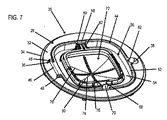
保持器28は、図7〜図9でより明確に見られ、リム部分32と、リム部分32の周りの窪んだリップ34とを有する。リム部分32は、実質的に平面であるが、この形態を有する必要はない。ヒンジ構成要素36がリム部分32上に配置、結合又は一体化され、ヒンジ構成要素36の反対側に凹部38が存在する。保持器28は、内部アパーチャ又は開口部42の周りに周辺シート40も含む。ヒンジ構成要素36は、したがって、シート40と保持器28の外周縁との間に位置する。
The
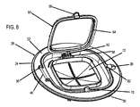
バッグ取り扱いアセンブリ26の第2の部分は、バッグ支持体44であり、これは、バッグ支持体44が保持器28に対して回動することを可能にするためにヒンジ構成要素36と嵌合するヒンジ構成要素46を含む。バッグ支持体44は、開口部を規定する略環状の形状を有し、環状は、バッグ支持体44の形状を限定することなく開口部を規定することを意味するために本明細書で使用される。ヒンジ構成要素36、46の構造は、ヒンジであろうと別の商品名で呼ばれていようと、回動運動を可能にするためにこれらの部分が相互作用する2つの構成要素のそれぞれにおける部分を含む任意の既知のタイプの構造であり得る。そのようなヒンジ構成要素36、46は、ヒンジ及びより一般的には回動可能な取り付け構造の分野に当業者によく知られている。
A second portion of the
例示的な一実施形態では、ヒンジ構成要素36は、保持器28のリム部分32から上方に突出する突起48の対を含み、ヒンジ構成要素46は、突起48によって各端部で回転可能に保持される細長いアクスルを含む。そのような構造並びにすべての均等物及び同等の構造は、バッグ支持体44を保持器28に回動可能に取り付けるための取り付け手段と呼ばれる。
In one exemplary embodiment, the
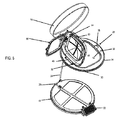
バッグ支持体44はまた、バッグ16の開放端が配置される内壁50と、下壁54によって内壁50から離間された外壁52とを含み、それにより下壁54の上及び内壁50と外壁52との間のチャネル56を規定する。内壁50及び外壁52の両方は、下壁54から共通の方向に隆起している。ヒンジ構成要素58は、下壁54上に配置されるか又は下壁54に一体化される。
The
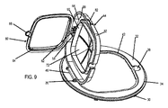
バッグ取り扱いアセンブリ26の第3の部分は、クロージャ構成要素60であり、これは、クロージャ構成要素60がバッグ支持体44に対して回動することを可能にするためにヒンジ構成要素58と嵌合するヒンジ構成要素62を含む。ヒンジ構成要素62は、延長片によりクロージャ構成要素60の環状部分から突出し、環状は、クロージャ構成要素60の形状を限定することなく開口部を規定することを意味するために本明細書で使用される。ヒンジ構成要素58、62の構造は、ヒンジであろうと別の名前で呼ばれていようと、回動運動を可能にするためにこれらの部品が相互作用する2つの構成要素のそれぞれにおける部分を含む任意の既知のタイプの構造であり得る。そのようなヒンジ構成要素58、62は、ヒンジ及びより一般的には回動可能な取り付け構造の分野の当業者によく知られている。
A third portion of the
例示的な一実施形態では、ヒンジ構成要素58は、バッグ支持体44の下壁54から上方に突出する突出構造を含み、ヒンジ構成要素62は、突出構造によって回転可能に保持される細長いアクスルを含む。そのような構造並びにすべての均等物及び同等の構造は、クロージャ構成要素60をバッグ支持体44に回動可能に取り付けるための取り付け手段と呼ばれる。
In one exemplary embodiment, the hinge component 58 comprises a protruding structure that projects upward from the
ヒンジ構成要素58、62(第2の取り付け手段)の組み合わせは、ヒンジ構成要素36、46(第1の取り付け手段)の組み合わせの半径方向内側に位置する。なぜなら、クロージャ構成要素60は、バッグ支持体44よりもサイズが小さく、バッグ支持体44は、保持器28よりもサイズが小さいからである。
The combination of hinge components 58, 62 (second mounting means) is located radially inside the combination of
クロージャ構成要素60がバッグ支持体44に対して下の位置にあるとき、バッグ16は、クロージャ構成要素60とバッグ支持体44との間で押される。より具体的には、クロージャ構成要素60は、下側にチャネル64を規定し、例えば図1及び図3〜図6を参照すると、それは、クロージャ構成要素60が回動して内壁50と係合すると、バッグ16(存在する場合)がクロージャ構成要素60と内壁50との間にクランプされるようにバッグ支持体44の内壁50を受け入れることができる。チャネル64は、一般に、2つの離間された壁及び底壁によって規定されて、下向きのチャネル64を形成する。したがって、クロージャ構成要素60は、内壁50の形状のような略正方形の形状を有するが、それらの形状は、変動し得る。
When the
したがって、バッグ支持体44は、2つの重要な機能を果たす。第1の機能は、例えば、廃棄物を保持するために使用されたときにバッグ16を取り除くために容器10の内部へのアクセスを可能にするように、保持器28に対する回動式取り付け具を提供することであり、第2の機能は、内壁50に対するクロージャ構成要素60によるバッグ16の開放端の選択的なクランプを可能にするために内壁50を提供することである。このクランプは、接触圧締めであり、バッグ16が内壁16に対してクロージャ構成要素60によって押し付けられ、それによりバッグ16内の材料から生じる臭気をバッグ16内に捕捉する。バッグが存在しない場合、クロージャ構成要素60と内壁50との間に接触が存在し得るか、又は容器10で使用される予定のバッグの厚さ未満のわずかな余裕のみが存在し得る。
Therefore, the
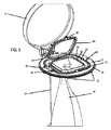
前者の機能に関して、バッグ支持体44は、協働式ヒンジ構造36、46によって上方に回動されて、バッグ16へのアクセスを可能にすることができる。図1及び図4、特に図6を参照されたい。図6には、バッグ支持体44が保持器28に対して上方に回動されている間の、廃棄物を含むバッグ16の除去が示されている。容器10からバッグを除去するためにバッグ支持体44が保持器28に対して上方に回動されるとき、クロージャ構成要素60がバッグ支持体44から離れるように上方に回動される必要はない。
With respect to the former function, the
バッグの除去は、バッグ16が満杯になるか又はバッグ16を交換することが望まれると、クロージャ構成要素60をバッグ支持体44に対して上方に回動させて、バッグ支持体44に対するクロージャ構成要素60のクランプ力を解放することによって促進される。図3を参照されたい。次に、バッグ16の端部をつかみ、場合により結んで、次にバッグ支持体44を通して容器10の内部に挿入する。次に、バッグ支持体44は、ユーザが指を保持器28の凹部38に挿入し、バッグ支持体44を上方に持ち上げることにより、保持器28に対して上方に回動され、それにより容器10の上部の開口部のサイズを大きくする。図4を参照されたい。最後に、バッグ16は、ユーザの手66によって把持され、容器10の内部から引き出される。図6を参照されたい。
To remove the bag, when the
次に、新しい単回使用バッグが調達され、容器10の内部に配置される。この配置は、バッグ支持体44が下向きに回動されて保持器28に載る前又は後のいずれかであり得る。前者の状況では、バッグ支持体44は、下向きに回動され、ユーザは、バッグ支持体44を通して手を伸ばしてバッグ16の上端に到達し、バッグ16を、バッグ支持体44を通して引っ張って、上端を内壁50の上に覆い垂らす必要がある。後者の状況では、ユーザは、バッグ16をバッグ支持体44に押し通し、次にバッグ16の上端を内壁50の上に覆い垂らす。両方の状況において、バッグ16の上端は、開放端が内壁50の上に覆い垂らされ、次にクロージャ構成要素60が内壁50に対して回動されて、この新しいバッグ16を使用可能な位置に固定する。
Next, a new single-use bag is procured and placed inside the
クロージャ構成要素60は、ヒンジ構成要素62の反対側に任意選択的なタブ68を含み、任意選択的な可撓性保持器70がバッグ支持体44の下壁54に配置される。タブ68は、保持器70のリップの下に押し付けることができ、それによりクロージャ構成要素60をバッグ支持体44に固定し、バッグ支持体44に対するクロージャ構成要素60の上方への回動運動を防止する。タブ68を保持器70から解放するために、保持器70を外側に曲げて、タブ68を上方に持ち上げることができる。タブ及び保持器の協働のさらなる詳細は、本出願人の以前の米国特許出願である、2017年1月23日出願の米国特許出願公開第15/413,163号、2015年11月9日出願の同第14/935,835号、2015年5月12日出願の同第14/709,878号、2014年11月10日出願の同第14/537,044号、2013年12月17日出願の同第14/109,270号、2013年9月23日出願の同第61/881,386号に開示されている。
The
協働するタブ68及び保持器70の代わりに、他の構造をバッグ支持体44及びクロージャ構成要素60に設け及び/又は一体化して、容器10の使用中にクロージャ構成要素60をバッグ支持体44に一時的に固定できるようにすることができる。一般に、そのような構造は、クロージャ構成要素60をバッグ支持体44に固定するための固定手段と呼ばれる。
Instead of the collaborating
バッグ支持体44は、内壁50及び/又は下壁54に取り付けることによってバッグ支持体44に一体化され得る任意選択的な膜72を含む。膜72は、バッグ支持体44とは別個の構成要素であり得、それに取り付けられ得る。示されるように、膜72は、2つの交差するチャネル74、76と、チャネル74、76から約45度の角度における2つの交差するスリット78、80とを含む。本発明にとって重要ではないため、チャネル及び/又はスリットの他の形成が膜72に提供され得る。開示された形成により、バッグ16内の任意の廃棄物に由来する臭気の放出を防止しながら、バッグ16をその中に保持されるようにチャネル74、76の1つに押し込むことが可能になる。バッグ16は、本明細書に記載の特許及び特許出願に開示された構造によって押し込むことができる。膜の追加の利点は、本明細書に記載の特許及び特許出願に詳述されている。実際、これらの特許及び特許出願に開示されたインサートアセンブリのすべての特徴は、本発明者により、可能な範囲で本発明のバッグ取り扱いアセンブリ26に組み込まれることが想定及び企図されており、本発明の一部と見なされるべきである。
The
バッグ16をそのクランプした状態から解放し、次に開口部のサイズを大きくするための2つの回動運動を含む上記のバッグの除去及び挿入手順の代わりに、外壁12にアクセスドアを備えた容器10を構築し、次にアクセスドアを開くことにより、廃棄物の入ったバッグ16にアクセスすることが可能である。空のバッグ16をアクセスドアから挿入し、次にその上端を膜72から上方に通過させ、次にその上端を内壁50の上に覆い垂らし、次にクロージャ構成要素60を閉じて、バッグ16の上端を内壁50とクロージャ構成要素60との間にクランプすることもできる。
A container with an access door on the
本発明の一実施形態では、保持器28は、容器10の外壁12に固定され、バッグ取り扱いアセンブリ26の残りの部分、すなわちバッグ支持体44及びクロージャ構成要素60は、本明細書に記載の本出願人の他の特許及び特許出願で使用される容器10又はインサートアセンブリへのインサート又は単一インサートと見なされる。このインサートは、ヒンジ構成要素46を押してヒンジ構成要素36と係合させることによって保持器28に取り付けられる。この実施形態では、保持器28は、適切なヒンジ構成要素36を含みながら、容器10に一体化することさえできる。スナップインタイプのヒンジは、回動可能な取り付け具の分野の当業者又はそのような装置の知識を有する人に知られている。
In one embodiment of the invention, the
容器10は、蓋14なしで使用することができる。さらに、バッグ取り扱いアセンブリ26は、他の受け器、例えば壁に取り付けられた受け器に取り付けることが可能である。したがって、バッグ取り扱いアセンブリ26は、バッグ取り扱いアセンブリ26によって保持されているときにバッグへの廃棄物の進入を制御し、また廃棄物で満杯になったときにバッグの除去を容易にするために使用される。
The
バッグ取り扱いアセンブリ26は、全体としてインサート又はインサートアセンブリとして形成することができ、保持器28は、廃棄物を受け入れるための受け器を規定する円筒容器又は他の支持構造の壁に取り付け可能であるように構成される。次に、保持器28は、支持構造に固定され、それにより、バッグ取り扱いアセンブリ26は、上に開示された方法で動作可能である。
The
容器10は、本明細書に記載の本出願人の特許及び特許出願に開示されている廃棄物処理構成要素と共に使用することができる。そのような廃棄物処理構成要素は、好ましくは、膜72と接触し(バッグが存在しない場合)、したがって膜72を押して、それによりその上のあらゆる廃棄物を、(バッグが存在する場合に)膜72によって保持されたバッグ16の開口部を通して膜72の下のバッグに押し込むように構成され得る。廃棄物処理構成要素は、挿入された廃棄物からの臭気を除去するために脱臭材料を放出する。
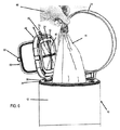
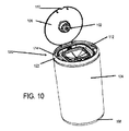
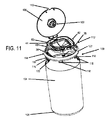
図10〜図12は、廃棄物処理構成要素102を備えたそのような容器100を示す。容器100は、実質的に円筒形である外壁104と、容器100に保持されたバッグ(図示せず)へのアクセスが可能である第1の開位置及びバッグ、より一般的には容器100の内部へのアクセスが防止される第2の閉位置を有する蓋106とを含む。外壁104は、廃棄物が入れられるバッグを受け入れることができる、容器100内の内部空間又は区画を規定する少なくとも1つの壁を表す。それは、単一の壁から構成され得るか又は複数の壁を含む。
10 to 12 show such a
容器100は、外壁104が支持されるベース部108も含む。蓋106は、手動で開けることができるようにするための窪み110を含む。蓋のそのような窪みは、容器10(図1〜図9)の蓋14に使用することができ、容器10(図1〜図9)の制御機構20は、容器100に使用することができる。廃棄物処理構成要素102は、蓋106の下側に取り付けられ、例えば脱臭材料を分配する。
The
容器100の一般的な特性は、本発明にとって重要ではなく、本発明は、本明細書に開示され且つ示されるタイプ及び形状に限定されることなく、任意のタイプ、形状及びサイズの容器で使用することができる。
The general properties of the
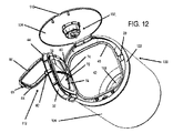
容器100は、バッグ取り扱いアセンブリ26と同様のバッグ取り扱いアセンブリ112を含み、相違点のみが言及される。バッグ取り扱いアセンブリ112は、バッグ支持体44及びクロージャ構成要素60並びに保持器28と類似しているが、わずかに異なる保持器114を含む(保持器28の特徴部と同じである保持器114の特徴部は、同じ参照番号で示されている)。1つの違いは、保持器114が外壁104に取り付けられる方法である。保持器114は、外壁104の内面上の同数の協働する突起120と協働する開口部118を備えた可撓性タブ116を含む。図11を参照されたい。突起120は、開口部118に適合するように寸法が定められている。したがって、保持器114、したがってバッグ取り扱いアセンブリ112全体は、容器100に恒久的に一体化されるのではなく、別個のアセンブリとして形成され、次いで外壁104と共に組み立てられて容器100を形成することができる。
The
一実施形態において、容器100を組み立てるために、バッグ支持体44及びクロージャ構成要素60が取り付けられた後又はそのような取り付け前に保持器114を回転させて、タブ116を突起120と位置合わせする。次に、保持器114を下向きに押すと、タブ116が内側に突起120を覆うように屈曲される。この押し込みは、タブ116が突起120を越えるまで続き、越えた時点において、タブ116は、外側に屈曲し、突起120は、タブ116の開口部118内に配置される。このようにして、保持器114、したがってバッグ取り扱いアセンブリ112全体の、容器100の外壁104への確実な取り付けが提供される。
In one embodiment, to assemble the
保持器114は、一般に、外壁104の断面形状と同じ形状を有するが、これは、保持器114に対する限定ではない。保持器114は、タブ116が下向きに突出するリム部分122を有する。ヒンジ構成要素36は、シート40とリム部分122との間に配置されている。
The
容器100は、廃棄物処理構成要素102に追加の機能を提供するように、具体的には膜72上に横たわるバッグ上の廃棄物を、膜72を通して作動可能に押すように構築され得る。この効果を提供するために、容器100は、廃棄物処理構成要素102が、膜72と蓋104の下面との間の距離と同じであるか又はそれよりもわずかに小さい高さを有するように構築される。したがって、蓋104が閉じられると、廃棄物処理構成要素102は、膜72上に横たわるバッグ上の廃棄物を、膜72を通して膜の下のバッグ部分に押し込む。
The
産業上の利用可能性
上の記載から、いくつかの特徴が明らかである。
Industrial Applicability From the above description, some characteristics are clear.
第1に、一体型バッグ取り扱いアセンブリ26は、2つの別個の独立した回動式取り付け手段又は回動式取り付け構造を含み、一方は、バッグ支持体44を保持器28に取り付けて、それらの間の相対運動を可能にするように構築及び配置され、もう一方は、クロージャ構成要素60をバッグ支持体44に取り付けて、それらの間の相対運動を可能にするように構築及び配置される。したがって、バッグ支持体44は、バッグ支持体44上に2つの別個のヒンジ構成要素46、58を含む。この二重の独立したヒンジ構造は、例えば、単回使用バッグと共に使用される廃棄物容器に大きい利点を提供する。なぜなら、バッグ支持体44は、使用中にバッグ16を固定するためのヒンジ構成要素36、46の1つの組と、容器10の内部からバッグ16を除去して空のバッグ16と交換しようとするとき、バッグ16への容易なアクセスを可能にするためのヒンジ構成要素58、62の別の組とを含むからである。
First, the integrated
第2に、示されるように、好ましい実施形態では、取り付け手段は、バッグ取り扱いアセンブリ26の同じ側に配置されない。むしろ、図1を参照すると、ヒンジ構成要素36、46は、バッグ取り扱いアセンブリ26の左側、すなわち保持器28によって規定された開口部42の左側に配置され、ヒンジ構成要素58、62は、バッグ取り扱いアセンブリ26の上側及び保持器28によって規定された開口部42の上方に配置される。ヒンジ構成要素36、46は、ヒンジ構成要素36、46の反対側のバッグ取り扱いアセンブリ26の右側に配置することもできる。ヒンジ構成要素をバッグ取り扱いアセンブリ26の異なる側に配置することにより、クロージャ構成要素60がバッグ支持体44に対して既に開かれている間、保持器28に対するバッグ支持体44の回動開放中の干渉が少ない。したがって、容器10の構造は、廃棄物で満杯のバッグにアクセスするためにクロージャ構成要素60及びバッグ支持体44の両方を開くとき、これらの回動運動のいずれも妨害しない。
Second, as shown, in a preferred embodiment, the mounting means are not located on the same side of the
本発明の特定の実施形態を示し且つ記載してきたが、そのより広い態様で本発明から逸脱することなく変更形態及び修正形態がなされ得ることが当業者に明らかであり、したがって、添付の特許請求の範囲の目的は、本発明の真の趣旨及び範囲内にあるようなすべてのそのような変更形態及び修正形態を網羅することである。実際、本明細書に開示されるバッグ取り扱いアセンブリ26、112の特徴の組み合わせを一緒に使用して、新しいバッグ取り扱いアセンブリを作り出すことができる。さらに、容器10の特徴は、容器100と組み合わせて使用することができ、その逆も可能である。また、2017年8月3日に出願された米国特許出願公開第15/668,414号の図64及び図65A〜図65Cに記載されているインサートの特徴は、バッグ取り扱いアセンブリ26、112で使用でき、‘414号出願で開示されている他のインサートの特徴は、容器10、100、特にバッグ取り扱いアセンブリ28、112でも使用することができる。本明細書に開示されるバッグ取り扱いアセンブリの特徴のそのような組み合わせ及び置き換えのすべては、本発明の一部と見なされる。
Although specific embodiments of the present invention have been shown and described, it will be apparent to those skilled in the art that modifications and modifications can be made in a broader manner without departing from the invention, and therefore the appended claims. The object of the scope of the invention is to cover all such modifications and modifications that are within the true meaning and scope of the invention. In fact, the combination of features of the
Claims (15)
前記少なくとも1つの壁に結合されたバッグ取り扱いアセンブリと、を含む容器であって、前記バッグ取り扱いアセンブリは、
前記少なくとも1つの壁の上端領域で前記少なくとも1つの壁から内側に延びる保持器であって、開口部を規定する保持器と、
前記保持器に回動可能に結合されたバッグ支持体であって、開口部を規定するバッグ支持体と、
前記保持器に対する前記バッグ支持体の回動可能な結合とは独立して前記バッグ支持体に回動可能に結合されたクロージャ構成要素であって、開口部を規定するクロージャ構成要素と、を含み、
前記バッグ支持体及び前記クロージャ構成要素は、前記クロージャ構成要素が前記バッグ支持体に対して回動されている間、前記バッグ支持体と前記クロージャ構成要素との間に前記バッグをクランプする協働式クランプ構造を含み、
それにより、前記バッグは、前記協働式クランプ構造によってクランプされ、且つ前記クロージャ構成要素が前記バッグ支持体に対して回動され、及び前記バッグ支持体が前記保持器に対して回動されている間、前記バッグ支持体及び前記保持器によって規定された前記開口部を通過し、且つ前記クロージャ構成要素、前記バッグ支持体及び前記保持器によって規定された前記開口部を通した前記バッグの内側へのアクセスを可能にする、容器。 With at least one wall that defines the interior space that can accommodate the bag,
A container comprising a bag handling assembly coupled to at least one wall, said bag handling assembly.
A cage that extends inward from the at least one wall in the upper end region of the at least one wall and defines an opening.
A bag support rotatably coupled to the cage, with a bag support defining an opening.
Includes closure components that are rotatably coupled to the bag support independently of the rotatable coupling of the bag support to the cage and that define an opening. ,
The bag support and the closure component work together to clamp the bag between the bag support and the closure component while the closure component is rotated relative to the bag support. Including formula clamp structure
Thereby, the bag is clamped by the collaborative clamp structure, and the closure component is rotated with respect to the bag support, and the bag support is rotated with respect to the cage. Inside the bag through the closure component, the bag support and the opening defined by the cage, while passing through the opening defined by the bag support and the cage. A container that allows access to.
前記クロージャ構成要素を前記バッグ支持体に回動可能に取り付けるための第2の取り付け手段と、をさらに含み、
前記第1の取り付け手段は、前記保持器によって規定された前記開口部の第1の側に位置し、及び前記第2の取り付け手段は、前記第1及び第2の取り付け手段が、前記保持器によって規定された前記開口部の異なる側にあるように、前記保持器によって規定された前記開口部の第2の側に位置する、請求項1に記載の容器。 A first mounting means for rotatably mounting the bag support to the cage, and
Further comprising a second mounting means for rotatably mounting the closure component to the bag support.
The first mounting means is located on the first side of the opening defined by the cage, and the second mounting means is such that the first and second mounting means are the cage. The container of claim 1, located on a second side of the opening as defined by the cage, such as on a different side of the opening as defined by.
前記クロージャ構成要素を前記バッグ支持体に回動可能に取り付けるための第2の取り付け手段と、をさらに含み、
前記第1の取り付け手段は、前記第1及び第2の取り付け手段が前記バッグ取り扱いアセンブリの中心から異なる距離にあるように、前記第2の取り付け手段の半径方向外側にある、請求項1に記載の容器。 A first mounting means for rotatably mounting the bag support to the cage, and
Further comprising a second mounting means for rotatably mounting the closure component to the bag support.
The first mounting means is claimed according to claim 1, wherein the first and second mounting means are radially outside the second mounting means so that the first and second mounting means are at different distances from the center of the bag handling assembly. Container.
前記保持器に対する前記バッグ支持体の回動運動を可能にするために前記保持器上の前記ヒンジ構成要素と協働する前記バッグ支持体上の第1のヒンジ構成要素と、
前記バッグ支持体上の第2のヒンジ構成要素と、
前記保持器に対する前記バッグ支持体の回動運動から独立した前記バッグ支持体に対する前記クロージャ構成要素の回動運動を可能にするために、前記バッグ支持体上の前記第2のヒンジ構成要素と協働する前記クロージャ構成要素上のヒンジ構成要素と、をさらに含む、請求項1に記載の容器。 With the hinge component on the cage,
A first hinge component on the bag support that cooperates with the hinge component on the cage to allow rotational movement of the bag support with respect to the cage.
With the second hinge component on the bag support,
In cooperation with the second hinge component on the bag support to allow rotational movement of the closure component with respect to the bag support independent of the rotational movement of the bag support with respect to the cage. The container according to claim 1, further comprising a hinge component on the closure component that works.
前記少なくとも1つの壁を支持するベース部と、
前記ベース部及び前記蓋に結合され、且つ前記蓋の開放及び閉鎖を制御する制御機構と、をさらに含む、請求項1に記載の容器。 A lid that moves between an open position where the bag handling assembly is accessible and allows waste to be inserted into the interior space, and a closed position where the bag handling assembly is inaccessible.
A base portion that supports at least one wall and
The container according to claim 1, further comprising a control mechanism coupled to the base portion and the lid and controlling the opening and closing of the lid.
Applications Claiming Priority (3)
| Application Number | Priority Date | Filing Date | Title |
|---|---|---|---|
| US15/923,532 US10053283B1 (en) | 2013-09-23 | 2018-03-16 | Waste container with bag handling assembly |
| US15/923,532 | 2018-03-16 | ||
| PCT/US2019/019385 WO2019177763A1 (en) | 2018-03-16 | 2019-02-25 | Waste container with bag handling assembly |
Publications (1)
| Publication Number | Publication Date |
|---|---|
| JP2021517543A true JP2021517543A (en) | 2021-07-26 |
Family
ID=67908016
Family Applications (1)
| Application Number | Title | Priority Date | Filing Date |
|---|---|---|---|
| JP2020549607A Pending JP2021517543A (en) | 2018-03-16 | 2019-02-25 | Waste container with bag handling assembly |
Country Status (5)
| Country | Link |
|---|---|
| EP (1) | EP3765387A4 (en) |
| JP (1) | JP2021517543A (en) |
| CN (1) | CN112105567A (en) |
| CA (1) | CA3094196A1 (en) |
| WO (1) | WO2019177763A1 (en) |
Families Citing this family (1)
| Publication number | Priority date | Publication date | Assignee | Title |
|---|---|---|---|---|
| US20250250106A1 (en) * | 2022-04-14 | 2025-08-07 | Angelcare Canada Inc. | Bag adapter for waste disposal device |
Citations (6)
| Publication number | Priority date | Publication date | Assignee | Title |
|---|---|---|---|---|
| JPH0280607U (en) * | 1988-12-09 | 1990-06-21 | ||
| JPH1175933A (en) * | 1997-09-08 | 1999-03-23 | Shiseido Co Ltd | Sealed container |
| JP2005001809A (en) * | 2003-06-11 | 2005-01-06 | Iwanori Nakada | Trash bin using bag body |
| JP3111367U (en) * | 2004-10-29 | 2005-07-28 | 双日株式会社 | Garbage can |
| US8266871B1 (en) * | 2010-07-07 | 2012-09-18 | David M Stravitz | Waste disposal devices with advanced control |
| CN202759680U (en) * | 2012-07-05 | 2013-02-27 | 中兴通讯股份有限公司 | a chassis |
Family Cites Families (21)
| Publication number | Priority date | Publication date | Assignee | Title |
|---|---|---|---|---|
| US7503152B2 (en) | 2001-05-02 | 2009-03-17 | Playtex Products, Inc. | Waste disposal device including rotating cartridge coupled to lid |
| US6612099B2 (en) | 2001-05-02 | 2003-09-02 | Saniquest Industries Corp. | Waste disposal devices including cartridge of flexible tubing |
| US7708188B2 (en) | 2001-05-02 | 2010-05-04 | Playtex Products, Inc. | Waste disposal device including a hamper accessible through a movable door |
| US7712285B2 (en) | 2001-05-02 | 2010-05-11 | Playtex Products, Inc. | Waste disposal device including a sensing mechanism for delaying the rotation of a cartridge |
| US7617659B2 (en) | 2001-05-02 | 2009-11-17 | Playtex Products, Inc. | Waste disposal device including a cartridge movable by rollers |
| US7146785B2 (en) | 2001-05-02 | 2006-12-12 | Stravitz David M | Waste disposal devices |
| US7434377B2 (en) | 2001-05-02 | 2008-10-14 | Playtex Products, Inc. | Waste disposal device including a rotatable geared rim to operate a cartridge |
| US7503159B2 (en) | 2001-05-02 | 2009-03-17 | Playtex Products, Inc. | Waste disposal device including an external actuation mechanism to operate a cartridge |
| US7316100B2 (en) | 2001-05-02 | 2008-01-08 | Playtex Products, Inc. | Waste disposal device including a film cutting and sealing device |
| CA2499016A1 (en) | 2002-07-31 | 2004-02-05 | David M. Stravitz | Waste disposal device |
| US7086569B2 (en) | 2003-01-06 | 2006-08-08 | Stravitz David M | All-purpose dispenser |
| TWM303190U (en) * | 2006-06-29 | 2006-12-21 | Thn Shong Ind Co Ltd | Rubbish bin with bag-clamping apparatus |
| WO2008023411A1 (en) * | 2006-08-23 | 2008-02-28 | Add Field Co., Ltd. | Garbage bin and lid for container |
| US8127519B2 (en) | 2008-07-14 | 2012-03-06 | Stravitz David M | Method of inserting and storing waste for disposal |
| US8215089B2 (en) | 2008-07-14 | 2012-07-10 | David Stravitz | Waste disposal devices |
| US8235237B1 (en) | 2008-12-17 | 2012-08-07 | David M Stravitz | Waste disposal device with self-closing lid |
| US7963414B1 (en) | 2008-12-17 | 2011-06-21 | Stravitz David M | Waste disposal device with self-closing lid |
| US20110170807A1 (en) * | 2010-01-12 | 2011-07-14 | Ideavillage Products Corp. | Flexible container closure |
| US8844751B2 (en) * | 2011-09-22 | 2014-09-30 | Pearhead, Inc. | Waste container |
| US8973774B1 (en) | 2014-02-25 | 2015-03-10 | David M. Stravitz | Waste container with actuatable, internal bag obstruction member |
| AU2015360235B2 (en) * | 2014-12-11 | 2020-03-05 | Munchkin, Inc. | Container for receiving multiple flexible bag assemblies |
-
2019
- 2019-02-25 WO PCT/US2019/019385 patent/WO2019177763A1/en not_active Ceased
- 2019-02-25 JP JP2020549607A patent/JP2021517543A/en active Pending
- 2019-02-25 EP EP19767212.4A patent/EP3765387A4/en not_active Withdrawn
- 2019-02-25 CA CA3094196A patent/CA3094196A1/en active Pending
- 2019-02-25 CN CN201980019250.0A patent/CN112105567A/en not_active Withdrawn
Patent Citations (6)
| Publication number | Priority date | Publication date | Assignee | Title |
|---|---|---|---|---|
| JPH0280607U (en) * | 1988-12-09 | 1990-06-21 | ||
| JPH1175933A (en) * | 1997-09-08 | 1999-03-23 | Shiseido Co Ltd | Sealed container |
| JP2005001809A (en) * | 2003-06-11 | 2005-01-06 | Iwanori Nakada | Trash bin using bag body |
| JP3111367U (en) * | 2004-10-29 | 2005-07-28 | 双日株式会社 | Garbage can |
| US8266871B1 (en) * | 2010-07-07 | 2012-09-18 | David M Stravitz | Waste disposal devices with advanced control |
| CN202759680U (en) * | 2012-07-05 | 2013-02-27 | 中兴通讯股份有限公司 | a chassis |
Also Published As
| Publication number | Publication date |
|---|---|
| EP3765387A4 (en) | 2021-12-01 |
| CA3094196A1 (en) | 2019-09-19 |
| EP3765387A1 (en) | 2021-01-20 |
| WO2019177763A1 (en) | 2019-09-19 |
| CN112105567A (en) | 2020-12-18 |
Similar Documents
| Publication | Publication Date | Title |
|---|---|---|
| US10053283B1 (en) | Waste container with bag handling assembly | |
| US8910821B1 (en) | Waste disposal devices with waste treatment component | |
| US9994392B1 (en) | Unitary insert for waste containers | |
| US7963414B1 (en) | Waste disposal device with self-closing lid | |
| US8973774B1 (en) | Waste container with actuatable, internal bag obstruction member | |
| US9573757B1 (en) | Waste treatment components | |
| US8266871B1 (en) | Waste disposal devices with advanced control | |
| US8127519B2 (en) | Method of inserting and storing waste for disposal | |
| US9056716B1 (en) | Waste container with actuatable, internal bag obstruction member | |
| US8215089B2 (en) | Waste disposal devices | |
| US10611564B1 (en) | Height adjustable waste disposal device with bag-grabbing membrane | |
| US9714138B2 (en) | Method for disposing waste packages such as diapers | |
| AU2015360235B2 (en) | Container for receiving multiple flexible bag assemblies | |
| US9834376B1 (en) | Closure components for securing a bag to a container | |
| US20100005762A1 (en) | Waste Disposal Devices | |
| US8739501B2 (en) | System for disposing waste packages such as diapers | |
| US10486899B1 (en) | Waste disposal device with bag-grabbing membrane | |
| US20110099957A1 (en) | System and method for disposing waste packages such as diapers | |
| US9555962B1 (en) | Waste containers with bag trapping structure | |
| US10343842B2 (en) | System and method for disposing waste packages such as diapers | |
| US20110099950A1 (en) | System and method for disposing waste packages such as diapers | |
| JP2021517543A (en) | Waste container with bag handling assembly | |
| JP5331205B2 (en) | Waste treatment equipment | |
| US11008162B1 (en) | Baby and adult-safe waste container with bag handling odor control assembly | |
| HK1246751B (en) | Container with waste chamber and supports for flexible bags |
Legal Events
| Date | Code | Title | Description |
|---|---|---|---|
| A621 | Written request for application examination |
Free format text: JAPANESE INTERMEDIATE CODE: A621 Effective date: 20220224 |
|
| A711 | Notification of change in applicant |
Free format text: JAPANESE INTERMEDIATE CODE: A711 Effective date: 20220224 |
|
| A521 | Request for written amendment filed |
Free format text: JAPANESE INTERMEDIATE CODE: A523 Effective date: 20220517 |
|
| A521 | Request for written amendment filed |
Free format text: JAPANESE INTERMEDIATE CODE: A523 Effective date: 20220517 |
|
| A977 | Report on retrieval |
Free format text: JAPANESE INTERMEDIATE CODE: A971007 Effective date: 20230322 |
|
| A131 | Notification of reasons for refusal |
Free format text: JAPANESE INTERMEDIATE CODE: A131 Effective date: 20230407 |
|
| A02 | Decision of refusal |
Free format text: JAPANESE INTERMEDIATE CODE: A02 Effective date: 20231031 |