JP2021522017A - Nests for supporting multiple medical containers, medical container packs containing this nest, and methods for manufacturing medical containers. - Google Patents
Nests for supporting multiple medical containers, medical container packs containing this nest, and methods for manufacturing medical containers. Download PDFInfo
- Publication number
- JP2021522017A JP2021522017A JP2020561675A JP2020561675A JP2021522017A JP 2021522017 A JP2021522017 A JP 2021522017A JP 2020561675 A JP2020561675 A JP 2020561675A JP 2020561675 A JP2020561675 A JP 2020561675A JP 2021522017 A JP2021522017 A JP 2021522017A
- Authority
- JP
- Japan
- Prior art keywords
- flange
- nest
- barrel
- medical container
- support structure
- Prior art date
- Legal status (The legal status is an assumption and is not a legal conclusion. Google has not performed a legal analysis and makes no representation as to the accuracy of the status listed.)
- Pending
Links
Images




Classifications
-
- A—HUMAN NECESSITIES
- A61—MEDICAL OR VETERINARY SCIENCE; HYGIENE
- A61M—DEVICES FOR INTRODUCING MEDIA INTO, OR ONTO, THE BODY; DEVICES FOR TRANSDUCING BODY MEDIA OR FOR TAKING MEDIA FROM THE BODY; DEVICES FOR PRODUCING OR ENDING SLEEP OR STUPOR
- A61M5/00—Devices for bringing media into the body in a subcutaneous, intra-vascular or intramuscular way; Accessories therefor, e.g. filling or cleaning devices, arm-rests
- A61M5/008—Racks for supporting syringes or needles
-
- A—HUMAN NECESSITIES
- A61—MEDICAL OR VETERINARY SCIENCE; HYGIENE
- A61M—DEVICES FOR INTRODUCING MEDIA INTO, OR ONTO, THE BODY; DEVICES FOR TRANSDUCING BODY MEDIA OR FOR TAKING MEDIA FROM THE BODY; DEVICES FOR PRODUCING OR ENDING SLEEP OR STUPOR
- A61M5/00—Devices for bringing media into the body in a subcutaneous, intra-vascular or intramuscular way; Accessories therefor, e.g. filling or cleaning devices, arm-rests
- A61M5/178—Syringes
- A61M5/31—Details
- A61M5/3129—Syringe barrels
-
- A—HUMAN NECESSITIES
- A61—MEDICAL OR VETERINARY SCIENCE; HYGIENE
- A61M—DEVICES FOR INTRODUCING MEDIA INTO, OR ONTO, THE BODY; DEVICES FOR TRANSDUCING BODY MEDIA OR FOR TAKING MEDIA FROM THE BODY; DEVICES FOR PRODUCING OR ENDING SLEEP OR STUPOR
- A61M5/00—Devices for bringing media into the body in a subcutaneous, intra-vascular or intramuscular way; Accessories therefor, e.g. filling or cleaning devices, arm-rests
- A61M5/178—Syringes
- A61M5/31—Details
- A61M5/3129—Syringe barrels
- A61M5/3135—Syringe barrels characterised by constructional features of the proximal end
-
- A—HUMAN NECESSITIES
- A61—MEDICAL OR VETERINARY SCIENCE; HYGIENE
- A61M—DEVICES FOR INTRODUCING MEDIA INTO, OR ONTO, THE BODY; DEVICES FOR TRANSDUCING BODY MEDIA OR FOR TAKING MEDIA FROM THE BODY; DEVICES FOR PRODUCING OR ENDING SLEEP OR STUPOR
- A61M5/00—Devices for bringing media into the body in a subcutaneous, intra-vascular or intramuscular way; Accessories therefor, e.g. filling or cleaning devices, arm-rests
- A61M5/178—Syringes
- A61M5/31—Details
- A61M5/3129—Syringe barrels
- A61M5/3137—Specially designed finger grip means, e.g. for easy manipulation of the syringe rod
-
- B—PERFORMING OPERATIONS; TRANSPORTING
- B29—WORKING OF PLASTICS; WORKING OF SUBSTANCES IN A PLASTIC STATE IN GENERAL
- B29C—SHAPING OR JOINING OF PLASTICS; SHAPING OF MATERIAL IN A PLASTIC STATE, NOT OTHERWISE PROVIDED FOR; AFTER-TREATMENT OF THE SHAPED PRODUCTS, e.g. REPAIRING
- B29C45/00—Injection moulding, i.e. forcing the required volume of moulding material through a nozzle into a closed mould; Apparatus therefor
- B29C45/0081—Injection moulding, i.e. forcing the required volume of moulding material through a nozzle into a closed mould; Apparatus therefor of objects with parts connected by a thin section, e.g. hinge, tear line
-
- B—PERFORMING OPERATIONS; TRANSPORTING
- B65—CONVEYING; PACKING; STORING; HANDLING THIN OR FILAMENTARY MATERIAL
- B65B—MACHINES, APPARATUS OR DEVICES FOR, OR METHODS OF, PACKAGING ARTICLES OR MATERIALS; UNPACKING
- B65B3/00—Packaging plastic material, semiliquids, liquids or mixed solids and liquids, in individual containers or receptacles, e.g. bags, sacks, boxes, cartons, cans, or jars
- B65B3/003—Filling medical containers such as ampoules, vials, syringes or the like
- B65B3/006—Related operations, e.g. scoring ampoules
-
- B—PERFORMING OPERATIONS; TRANSPORTING
- B65—CONVEYING; PACKING; STORING; HANDLING THIN OR FILAMENTARY MATERIAL
- B65D—CONTAINERS FOR STORAGE OR TRANSPORT OF ARTICLES OR MATERIALS, e.g. BAGS, BARRELS, BOTTLES, BOXES, CANS, CARTONS, CRATES, DRUMS, JARS, TANKS, HOPPERS, FORWARDING CONTAINERS; ACCESSORIES, CLOSURES, OR FITTINGS THEREFOR; PACKAGING ELEMENTS; PACKAGES
- B65D21/00—Nestable, stackable or joinable containers; Containers of variable capacity
- B65D21/02—Containers specially shaped, or provided with fittings or attachments, to facilitate nesting, stacking, or joining together
- B65D21/0201—Containers specially shaped, or provided with fittings or attachments, to facilitate nesting, stacking, or joining together stackable or joined together side-by-side
-
- A—HUMAN NECESSITIES
- A61—MEDICAL OR VETERINARY SCIENCE; HYGIENE
- A61M—DEVICES FOR INTRODUCING MEDIA INTO, OR ONTO, THE BODY; DEVICES FOR TRANSDUCING BODY MEDIA OR FOR TAKING MEDIA FROM THE BODY; DEVICES FOR PRODUCING OR ENDING SLEEP OR STUPOR
- A61M5/00—Devices for bringing media into the body in a subcutaneous, intra-vascular or intramuscular way; Accessories therefor, e.g. filling or cleaning devices, arm-rests
- A61M5/178—Syringes
- A61M5/31—Details
- A61M5/3129—Syringe barrels
- A61M5/3137—Specially designed finger grip means, e.g. for easy manipulation of the syringe rod
- A61M2005/3139—Finger grips not integrally formed with the syringe barrel, e.g. using adapter with finger grips
-
- A—HUMAN NECESSITIES
- A61—MEDICAL OR VETERINARY SCIENCE; HYGIENE
- A61M—DEVICES FOR INTRODUCING MEDIA INTO, OR ONTO, THE BODY; DEVICES FOR TRANSDUCING BODY MEDIA OR FOR TAKING MEDIA FROM THE BODY; DEVICES FOR PRODUCING OR ENDING SLEEP OR STUPOR
- A61M5/00—Devices for bringing media into the body in a subcutaneous, intra-vascular or intramuscular way; Accessories therefor, e.g. filling or cleaning devices, arm-rests
- A61M5/178—Syringes
- A61M5/31—Details
- A61M5/3129—Syringe barrels
- A61M2005/3142—Modular constructions, e.g. supplied in separate pieces to be assembled by end-user
-
- B—PERFORMING OPERATIONS; TRANSPORTING
- B29—WORKING OF PLASTICS; WORKING OF SUBSTANCES IN A PLASTIC STATE IN GENERAL
- B29C—SHAPING OR JOINING OF PLASTICS; SHAPING OF MATERIAL IN A PLASTIC STATE, NOT OTHERWISE PROVIDED FOR; AFTER-TREATMENT OF THE SHAPED PRODUCTS, e.g. REPAIRING
- B29C45/00—Injection moulding, i.e. forcing the required volume of moulding material through a nozzle into a closed mould; Apparatus therefor
- B29C2045/0086—Runner trees, i.e. several articles connected by a runner
-
- B—PERFORMING OPERATIONS; TRANSPORTING
- B65—CONVEYING; PACKING; STORING; HANDLING THIN OR FILAMENTARY MATERIAL
- B65B—MACHINES, APPARATUS OR DEVICES FOR, OR METHODS OF, PACKAGING ARTICLES OR MATERIALS; UNPACKING
- B65B2230/00—Aspects of the final package
- B65B2230/02—Containers having separate compartments isolated from one another
Landscapes
- Health & Medical Sciences (AREA)
- Engineering & Computer Science (AREA)
- Animal Behavior & Ethology (AREA)
- General Health & Medical Sciences (AREA)
- Biomedical Technology (AREA)
- Heart & Thoracic Surgery (AREA)
- Hematology (AREA)
- Life Sciences & Earth Sciences (AREA)
- Vascular Medicine (AREA)
- Anesthesiology (AREA)
- Public Health (AREA)
- Veterinary Medicine (AREA)
- Mechanical Engineering (AREA)
- Manufacturing & Machinery (AREA)
- Medical Preparation Storing Or Oral Administration Devices (AREA)
- Infusion, Injection, And Reservoir Apparatuses (AREA)
- Packages (AREA)
Abstract
本発明に係るネスト(1)は、複数の破壊可能な接続ブリッジ(10)と、所定のパターンで配置され、医療用容器(100)のフランジを形成するように構成された複数のフランジ(50)であって、フランジ(50)が前記破壊可能な接続ブリッジ(10)に接続されている、フランジ(50)と、前記フランジ(50)を支持するように前記破壊可能な接続ブリッジ(10)に取り付けられた支持構造(30)と、を備える。前記フランジ(50)は、破壊可能な接続ブリッジ(10)および支持構造(30)と一体的に形成されている。The nest (1) according to the present invention includes a plurality of destructible connecting bridges (10) and a plurality of flanges (50) arranged in a predetermined pattern and configured to form a flange of a medical container (100). ), The flange (50) is connected to the destructible connecting bridge (10), and the destructible connecting bridge (10) so as to support the flange (50). It comprises a support structure (30) attached to the. The flange (50) is integrally formed with a destructible connecting bridge (10) and a support structure (30).
Description
本発明は、複数の医療用容器を支持するための保持装置、この保持装置を含む医療用容器パック、および医療用容器の製造方法に関する。 The present invention relates to a holding device for supporting a plurality of medical containers, a medical container pack including the holding device, and a method for manufacturing a medical container.
本出願において、構成部分または装置の遠位端は、ユーザの手から最も遠い端を意味すると理解され、近位端は、ユーザの手に最も近い端を意味すると理解されるべきである。同様に、本出願において、「遠位方向」は、本発明の包装装置に含まれる医療用容器に関して、注射の方向を意味すると理解され、「近位方向」は、上記注射の方向とは反対の方向、すなわち、注射操作に関して、医療用容器を保持しているユーザの手に向かう方向を意味すると理解されるべきである。 In the present application, the distal end of a component or device should be understood to mean the end farthest from the user's hand, and the proximal end should be understood to mean the end closest to the user's hand. Similarly, in the present application, "distal direction" is understood to mean the direction of injection with respect to the medical container included in the packaging device of the present invention, and "proximal direction" is opposite to the direction of injection described above. It should be understood to mean the direction of, i.e., towards the hand of the user holding the medical container with respect to the injection operation.
プレフィルド可能なシリンジ(pre-fillable syringe)またはプレフィルドシリンジ(prefilled syringe)などの医療用容器は、多くの場合、ある場所から別の場所に、例えば製造現場から、ワクチン、薬または治療薬等の医薬組成物を医療用容器に充填できる別の場所に輸送する必要がある。それほど頻繁ではないが、医療用容器は同じ最初の場所で製造および充填されてから、保管場所に輸送される場合がある。輸送中、医療用容器は通常、ネスト(nest)とも呼ばれる保持装置によって保持される。ネストは箱型の槽(tub)の中に置かれ、1つの開口部はシーリングカバーで密閉されている。この槽から医療用容器を取り外すには、基本的に、密封カバーを剥がし、医療用容器を保持しているネストを槽から取り外し、次に医療用容器をネストに対して軸方向にスライドさせることによって医療用容器をネストから取り外す必要がある。ネストから取り出されて個別に包装される前に、医療用容器は、充填機によって医薬組成物で充填される。 Medical containers such as pre-fillable syringes or prefilled syringes are often medicines such as vaccines, drugs or therapeutics from one location to another, eg from the manufacturing floor. The composition needs to be transported to another location where it can be filled into a medical container. Less often, medical containers may be manufactured and filled in the same initial location before being shipped to storage. During transportation, the medical container is usually held by a holding device, also called a nest. The nest is placed in a box-shaped tub and one opening is sealed with a sealing cover. To remove the medical container from this tank, basically remove the sealing cover, remove the nest holding the medical container from the tank, and then slide the medical container axially with respect to the nest. Needs to remove the medical container from the nest. The medical container is filled with the pharmaceutical composition by a filling machine before being removed from the nest and individually packaged.
ネストは板状のトレーで、一般的に100個以上の医療用容器を支えるように構成されている。通常、ネストは、所定の列に従って整列されたいくつかの穴を含み、各穴は、医療用容器のフランジが板状のネストの1つの面に載るまで、1つの医療用容器のバレルの挿入を可能にするように構成される。 Nests are plate-shaped trays that are generally configured to support more than 100 medical containers. Usually, the nest contains several holes arranged according to a predetermined row, and each hole inserts a barrel of one medical container until the flange of the medical container rests on one surface of the plate-shaped nest. Is configured to enable.
但し、医療用容器は、輸送中またはネストが充填ラインで処理されるときに、ネストに対してわずかに移動する可能性がある。結果として、医療用容器は、医薬組成物で充填されたときに、充填針に対して適切に中心に置かれない可能性がある。さらに、注射器のネスト解除(denesting)は、充填ラインで発生する可能性がある。輸送中、クリアランス(clearance)は隣接するコンテナ間の衝撃を伴い、場合によっては外観上の欠陥やコンテナの破損につながる可能性がある。 However, the medical container may move slightly relative to the nest during transport or when the nest is processed on the filling line. As a result, the medical container may not be properly centered with respect to the filling needle when filled with the pharmaceutical composition. In addition, syringe denesting can occur at the filling line. During shipping, clearance is accompanied by impact between adjacent containers, which can lead to cosmetic defects and container damage in some cases.
さらに、注射器などの医療用容器は、典型的には、医薬組成物を収容するためのリザーバを画成する細長いバレル、バレル内に配置されたプランジャストッパ、バレル内のプランジャストッパを移動させ、バレルの遠位端にあるかしめられた針および/またはニードルシールド、およびバレルの近位端にあるフランジによって先端が閉じられている。フランジは、プランジャロッドが親指で作動している間、ユーザの指、通常は人差し指と中指を配置するための表面を提供する。医療用容器は、ガラスまたはプラスチック材料で作られ得る。 In addition, medical containers such as syringes typically move and barrel an elongated barrel that defines a reservoir for containing the pharmaceutical composition, a plunger stopper located within the barrel, and a plunger stopper within the barrel. The tip is closed by a crimped needle and / or needle shield at the distal end of the barrel and a flange at the proximal end of the barrel. The flange provides a surface for placing the user's fingers, usually the index and middle fingers, while the plunger rod is operating with the thumb. Medical containers can be made of glass or plastic material.
ガラス製の医療用容器の製造工程では、先端の前にフランジが形成される。次に、フランジは、先端を形成する際の支持および基準として機能する。但し、フランジは必ずしも完全に平面であるとは限らない。したがって、チップを形成する際に不正確さが生じる可能性がある。これにより、デッドボリュームが増加したり、注射器の長さが不完全に制御されたりする可能性がある。デッドボリュームとは、注射器から別の装置に医薬組成物を移した後、先端に残っている医薬組成物の量であることを理解されるべきである。一方では医薬組成物の浪費を最小限に抑えるために、他方では投与される医薬組成物の量の正確さの理由から、デッドボリュームは可能な限り小さいことが望ましい。 In the manufacturing process of a glass medical container, a flange is formed in front of the tip. The flange then serves as a support and reference in forming the tip. However, the flange is not always completely flat. Therefore, inaccuracies can occur in forming the chips. This can increase dead volume and improperly control the length of the syringe. It should be understood that dead volume is the amount of pharmaceutical composition remaining at the tip after transferring the pharmaceutical composition from the syringe to another device. It is desirable that the dead volume be as small as possible, on the one hand, to minimize waste of the pharmaceutical composition, and on the other hand, for the sake of accuracy in the amount of pharmaceutical composition administered.
本発明の一態様は、医療用容器を支持するための保持装置であり、保持装置は、医療用容器の充填ライン上での改善されたセンタリング(centering)を可能にし、それにより、医療用容器が充填ライン上または輸送中に脱落または破損するのを防ぎ、またデッドボリュームを減少させることを可能にし、医療用容器の長さをよりよく制御する。 One aspect of the invention is a holding device for supporting a medical container, which allows for improved centering on the filling line of the medical container, thereby the medical container. Prevents falling or breaking on the filling line or during transportation, and also allows the dead volume to be reduced, better controlling the length of the medical container.
本発明の一態様は、複数の医療用容器を保持するための保持装置であって、
複数の破壊可能な接続ブリッジ(breakable connecting bridge)と、
所定のパターンで配置され、医療用容器のフランジを形成するように構成された複数の破壊可能なフランジであって、フランジは、破壊可能な接続ブリッジに接続されている、複数のフランジと、
複数のフランジを支持するために、破壊可能な接続ブリッジに取り付けられた支持構造と、を備える保持装置である。
One aspect of the present invention is a holding device for holding a plurality of medical containers.
With multiple breakable connecting bridges,
A plurality of destructible flanges arranged in a predetermined pattern and configured to form a flange of a medical container, wherein the flange is connected to a destructible connecting bridge.
A holding device comprising a support structure attached to a destructible connecting bridge to support a plurality of flanges.
ここで、フランジは、破壊可能な接続ブリッジおよび支持構造と一体的に形成されている。 Here, the flange is integrally formed with a destructible connecting bridge and support structure.
この保持装置は、医療用容器のフランジが破壊可能な接続ブリッジによって支持構造に取り付けられているため、医療用容器の充填ライン上での改善されたセンタリングを可能にする。フランジは支持構造に固定されているため、充填作業中や輸送中に医療用容器が衝撃を受けるのを防ぐ。 This holding device allows improved centering on the filling line of the medical container because the flange of the medical container is attached to the support structure by a destructible connecting bridge. The flange is fixed to the support structure to prevent the medical container from being impacted during filling and transportation.
保持装置はネストを指し得る。 The holding device can point to a nest.
有利には、破壊可能な接続ブリッジは、フランジの1つに取り付けられた第1の端部と、別のフランジまたは支持構造に取り付けられた第2の端部とを備える。 Advantageously, the destructible connecting bridge comprises a first end attached to one of the flanges and a second end attached to another flange or support structure.
有利には、第1の端部は、フランジに向かって減少する厚さを有する。 Advantageously, the first end has a thickness that decreases towards the flange.
有利には、第2の端部は、他のフランジまたは支持構造に向かって減少する厚さを有する。 Advantageously, the second end has a thickness that diminishes towards other flanges or support structures.
これらの機能により、接続ブリッジが破損した後のフランジエッジが滑らかになる。 These features smooth the flange edges after the connecting bridge is broken.
有利には、破壊可能な接続ブリッジは、第1の端部と第2の端部との間に挿入された中間部分を含む。 Advantageously, the destructible connecting bridge includes an intermediate portion inserted between the first end and the second end.
フランジは、好ましくは、破壊可能な接続ブリッジによって支持構造に取り付けられる。 The flange is preferably attached to the support structure by a destructible connecting bridge.
有利には、少なくとも幾つかの隣接するフランジは、1つまたは幾つかの破壊可能な接続ブリッジのみによって互いに分離されている。 Advantageously, at least some adjacent flanges are separated from each other by only one or several destructible connecting bridges.
したがって、これらのフランジは、少なくとも1つの破壊可能な接続ブリッジによって隣接するフランジに直接接続される。 Therefore, these flanges are directly connected to adjacent flanges by at least one destructible connecting bridge.
これにより、単位面積あたりの保持装置が保持するフランジの数を増やすことができる。 This makes it possible to increase the number of flanges held by the holding device per unit area.
一実施形態では、支持構造は板状のネストである。フランジは板状でもよい。フランジとネストは同一平面上にあり得る。 In one embodiment, the support structure is a plate-like nest. The flange may be plate-shaped. Flange and nest can be coplanar.
有利には、支持構造は、複数の貫通開口部を区切っており、各フランジは、貫通開口部の1つの内側に延びている。 Advantageously, the support structure separates a plurality of through openings, each flange extending inward of one of the through openings.
一実施形態では、各フランジは、セグメント化された溝(segmented groove)によって囲まれている。有利には、各フランジは少なくとも2つのスロットによって囲まれ、2つの連続するスロットは、破壊可能な接続ブリッジによって分離されている。スロットは、支持構造とフランジの間に延びている。したがって、フランジを囲むスロットは、セグメント化された溝を形成する。 In one embodiment, each flange is surrounded by a segmented groove. Advantageously, each flange is surrounded by at least two slots, and the two consecutive slots are separated by a destructible connecting bridge. The slot extends between the support structure and the flange. Therefore, the slots surrounding the flange form segmented grooves.
一実施形態では、各フランジは、少なくとも2つの破壊可能な接続ブリッジによって、好ましくは3つ、より好ましくは4つの破壊可能な接続ブリッジによって支持構造に接続されている。これにより、フランジを安定した平面構成に保つことができる。 In one embodiment, each flange is connected to the support structure by at least two destructible connecting bridges, preferably three, more preferably four destructible connecting bridges. As a result, the flange can be maintained in a stable planar configuration.
一実施形態では、支持構造は、周縁(peripheral edge)を含み、周縁は、破壊可能な接続ブリッジによって複数のフランジの外周フランジ(peripheral flange)に接続されている。 In one embodiment, the support structure includes a peripheral edge, which is connected to the peripheral flanges of a plurality of flanges by a destructible connecting bridge.
周縁は、フランジを同じ平面に保持するように保持装置を補強しながら、充填ライン上または輸送中に保持装置の取り扱いを可能にする。 The periphery allows the holding device to be handled on the filling line or in transit, while reinforcing the holding device to hold the flange in the same plane.
一実施形態では、支持構造は、隣接するフランジの列の間に延びている補強バー(reinforcing bar)を含む。 In one embodiment, the support structure includes a reinforcing bar extending between adjacent rows of flanges.
これにより、支持構造を補強し、支持構造を平面分布(planar distribution)に維持して、充填ラインの精度を向上させることができる。 This can reinforce the support structure, maintain the support structure in a planar distribution, and improve the accuracy of the filling line.
一実施形態では、補強バーは、2列のフランジの間に挿入された破壊可能な接続ブリッジの下に延びている。これにより、フランジをより近くに保持できるため、保持装置は単位面積あたりにより多くのフランジを保持できる。より正確には、補強バーは、破壊可能な接続ブリッジの中間部分に取り付けることができる。 In one embodiment, the reinforcing bar extends under a destructible connecting bridge inserted between the two rows of flanges. This allows the flanges to be held closer so that the holding device can hold more flanges per unit area. More precisely, the reinforcing bar can be attached to the middle part of the destructible connecting bridge.
有利には、補強バーはネストに取り付けられている。補強バーは、上記のネストの片側に延びている。 Advantageously, the reinforcing bars are attached to the nest. The reinforcement bar extends to one side of the nest above.
有利には、補強バーは幅よりも高い。 Advantageously, the reinforcing bar is higher than the width.
補強バーは、長方形の断面形状を有し得る。 The reinforcing bar may have a rectangular cross-sectional shape.
有利には、支持構造は、第1の方向に平行な第1の組の補強バーと、前記第1の方向と交差する第2の方向に平行な第2の組の補強バーとを備える。 Advantageously, the support structure comprises a first set of reinforcing bars parallel to the first direction and a second set of reinforcing bars parallel to the second direction intersecting the first direction.
一実施形態では、保持装置は、医療用容器のうちの1つのバレルをフランジに固定するように構成された固定手段を備える。これにより、医療用容器を保持装置に固定することができるため、医療用容器を形成している間、医療用容器が充填ライン上または輸送中に移動することができない。 In one embodiment, the holding device comprises fixing means configured to secure one barrel of the medical container to a flange. As a result, the medical container can be fixed to the holding device, so that the medical container cannot be moved on the filling line or during transportation while forming the medical container.
一実施形態では、固定手段は、各フランジから延びている案内導管(guiding conduit)を含み、案内導管は、バレルを受容するように構成される。これにより、充填ラインのセンタリングがより適切になる。 In one embodiment, the fixing means includes a guiding conduit extending from each flange, the guiding conduit being configured to receive the barrel. This makes the centering of the filling line more appropriate.
案内導管は、バレル、例えばガラス材料で作られたバレルをフランジに固定するように構成された固定要素を備えていてもよい。 The guide conduit may include a fixing element configured to secure the barrel, eg, a barrel made of glass material, to the flange.
実施形態において:
- 案内導管は、バレルをフランジに固定するように接着剤(adhesive)を受容するように構成された取り付け面を備える。
- 案内導管は、バレルをフランジに固定するように構成された摩擦嵌合面(friction-fit surface)を含む。有利なことに、摩擦嵌合面は、熱可塑性エラストマーまたはゴムで作られている。有利には、案内導管は、フランジに取り付けられたリングを含み、摩擦嵌合面は、このリングの内壁に提供される。有利には、このリングは、案内導管の溝に挿入される。
- 案内導管は、バレルに設けられた相補的な形状のクリッピング要素に嵌合するように構成されたクリッピング要素を備える。
In an embodiment:
--The guide conduit has a mounting surface configured to receive an adhesive to secure the barrel to the flange.
--The guide conduit includes a friction-fit surface configured to secure the barrel to the flange. Advantageously, the friction fitting surface is made of thermoplastic elastomer or rubber. Advantageously, the guide conduit includes a ring attached to the flange, and a friction fitting surface is provided on the inner wall of this ring. Advantageously, this ring is inserted into the groove of the guide conduit.
--The guide conduit comprises a clipping element configured to fit into a complementary shaped clipping element provided on the barrel.
有利には、各フランジは、案内導管へのバレルの挿入をブロックするように構成された軸方向ストップを備える。これにより、バレルの正確な位置決めが可能になる。 Advantageously, each flange comprises an axial stop configured to block the insertion of the barrel into the guide conduit. This allows accurate positioning of the barrel.
有利には、軸方向ストップは先細の側面を含む。これにより、充填ラインをより適切にセンタリングできる。 Advantageously, the axial stop includes tapered sides. This allows the filling line to be more appropriately centered.
本発明の別の態様は、保持装置および複数の医療用容器を含む医療用容器パックであり、医療用容器はガラス製のバレルを有し、バレルは保持装置のフランジの1つに固定されている。 Another aspect of the invention is a medical container pack comprising a holding device and a plurality of medical containers, the medical container having a glass barrel, the barrel fixed to one of the flanges of the holding device. There is.
その結果、各医療用容器は保持装置に適切に固定され、充填ラインのセンタリングが改善され、対応する接続ブリッジを破壊することによってこの支持構造から取り外し可能になる。 As a result, each medical container is properly secured to the holding device, the centering of the filling line is improved, and it becomes removable from this support structure by breaking the corresponding connecting bridge.
本発明の別の態様は、保持装置および複数の医療用容器を含む医療用容器パックであり、医療用容器はプラスチック材料で作られたバレルを有し、バレルおよび保持装置は単一の部品に成形される。その結果、バレルは保持装置と一体的に形成される。バレルと保持装置は単一の部品である。 Another aspect of the invention is a medical container pack containing a holding device and a plurality of medical containers, the medical container having a barrel made of a plastic material, the barrel and the holding device in a single component. It is molded. As a result, the barrel is formed integrally with the holding device. The barrel and holding device are a single part.
本発明の別の態様は、医療用容器の製造方法であって、
- 上記のように医療用容器パックを準備するステップと、
- 対応する医療用容器を医療用容器パックから取り外すために、フランジの1つを支持構造に固定している接続ブリッジを破壊するステップと、を含む。
Another aspect of the present invention is a method for manufacturing a medical container.
--The steps to prepare the medical container pack as described above,
—— Includes the step of breaking the connecting bridge that secures one of the flanges to the support structure in order to remove the corresponding medical container from the medical container pack.
有利には、当該方法は、バレルをフランジの開口部に挿入し、医療用容器パックを形成するために前記バレルをフランジに固定するステップを含む。 Advantageously, the method comprises inserting the barrel into the opening of the flange and fixing the barrel to the flange to form a medical container pack.
有利には、当該方法は、医療用容器パックを形成するために、バレルおよびフランジを単一の部品に成形するステップを含む。有利には、当該方法は、バレルおよびフランジを単一の部品に成形するステップ中に各バレルが針の1つにオーバーモールド(overmold)されるように、型(mold)に針を配置する前のステップを含む。 Advantageously, the method involves molding the barrel and flange into a single part to form a medical container pack. Advantageously, the method is before placing the needle in the mold so that each barrel is overmolded into one of the needles during the step of molding the barrel and flange into a single part. Includes steps.
本発明およびそれから生じる利点は、以下の添付の図面を参照して以下に示す詳細な説明から明らかになる。
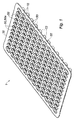
図1を参照して、本発明による保持装置1が示されている。保持装置1は、図4に示すように、複数の医療用容器100を同時に支持するように構成される。したがって、保持装置1は、医療用容器100の充填ライン上での包装、保管、輸送、および取り扱いのためのネストとして機能する。医療用容器100は、プレフィルド可能なシリンジなどの注射器であり得ることに留意されたい。医療用容器100は、充填後、ワクチン、医薬品、または治療用医薬組成物などの医薬組成物を含むことを意図している。
The holding
保持装置1は、以下でさらに詳細に説明するように、複数の破壊可能な接続ブリッジ10、支持構造30、支持構造30に取り付けられた破壊可能なブリッジ10、および医療用容器100のフランジ50を形成するように構成された複数のフランジ50を備える。
The holding
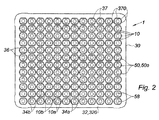
破壊可能な接続ブリッジ10は、各フランジ50を別の隣接するフランジ50または支持構造30に接続し、その結果、フランジ50は、所定のパターンに従って一緒に保持される。図2に示されるように、フランジ50は、平行な列に整列され得る。その上、フランジ50は、好ましくは同じ平面内に延びており、その結果、保持装置は実質的に板状の構成を有する。
The destructible connecting
破壊可能な接続ブリッジ10は、フランジ50が支持構造30から分離されることを可能にするために、それらに十分な力が加えられたときに切断または破壊されるように構成される。結果として、フランジ50は、取り外し可能な方法で、接続ブリッジ10に接続され、したがって互いに、および/または支持構造30に接続される。
The destructible connecting
フランジ50は、破壊可能な接続ブリッジ10によって支持構造30から分離されている。したがって、各フランジ50は、破壊可能な接続ブリッジ10のみによって保持装置1に取り付けられている。
The
図2に示されるように、各フランジ50は、セグメント化された溝37によって囲まれている。溝37は貫通開口部である。セグメント化された溝37は、フランジ50を支持フレーム30に連結するように構成された破壊可能な接続ブリッジ10と交差している。溝37は、対応するフランジ50と支持構造30との間に延びている。
As shown in FIG. 2, each
各フランジ50は、少なくとも2つのスロット370によって取り囲まれ得、2つの連続するスロット370は、破壊可能な接続ブリッジ10によって分離されている。スロット370は、支持構造30とフランジ50との間に延びている。したがって、フランジ50を取り囲むスロット370は、セグメント化された溝37を形成する。
Each
支持構造30は、フランジ50が破壊可能な接続ブリッジ10によってこの支持構造30に接続されている限り、フランジ50を固定位置に維持するように構成される。したがって、支持構造30は、複数のフランジ50を固定可能に支持するための補強手段を形成する。
The
支持構造30は、破壊可能な接続ブリッジ10の全てまたは少なくとも幾つかを接続する。例えば、図1に示すように、隣接する接続ブリッジ10間を延びているか、図5Bに示すように、接続ブリッジ10の上または下に延びている。結果として、各フランジ50は、支持構造30に接続され得るか、または各フランジ50は、破壊可能な接続ブリッジ10の少なくとも1つによって隣接するフランジ50に接続され得る。
The
1つの好ましい実施形態によれば、支持フレーム30は、複数の貫通開口部36を含むプレート(plate)である。少なくとも1つのフランジ50が各貫通開口部36に延びており、フランジ50は、少なくとも2つの破壊可能な接続ブリッジ10によって、好ましくは3つ、より好ましくは4つの破壊可能な接続ブリッジ10によって支持フレーム30に接続される。当該プレートは好ましくは長方形である。
According to one preferred embodiment, the
フランジ50は、破壊可能な接続ブリッジ10および支持構造30と一体的に形成されている。換言すれば、フランジ50、破壊可能な接続ブリッジ10、および支持構造30は、単一の部品である。結果として、保持装置1は、一体化された注射器フランジ50を備えたネストである。
The
好ましくは、フランジ50、破壊可能な接続ブリッジ10、および支持フレームは、ポリプロピレンなどのプラスチック材料である。フランジ50、破壊可能な接続ブリッジ10、および支持構造30は、単一の部品に成形されている。
Preferably, the
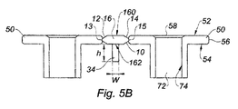
フランジ50は、医療用容器100のフランジ50として機能するように構成される。フランジ50は板状であり得る。それらは、2つの対向する平面52、54、すなわち、近位面52および遠位面54を有し得る。近位面52は、このフランジ50に取り付けられた接続ブリッジ10を破壊するためにフランジ50に力を加えるための押圧面として機能し得る。あるいは、この力は、遠位面54に加えられ得る。遠位面54は、医療用容器100が使用されているときに、ユーザの指(一般に、人差し指および中指)を受容するように構成される。近位面および遠位面52、54は、周縁56によって結合されている。図5Bに見られるように、破壊可能な接続ブリッジ10は、好ましくは、フランジ50の縁56に固定されている。フランジ50は、中央開口部58を区切っている。中央開口部58は、医療用容器100のプランジャロッドを受容するように構成される。フランジ50は、好ましくは、ユーザの指に十分な受容領域を提供するために半径方向に延びる2つの正反対のアーム60を備える。これらの2つのアーム60は、2つの正反対の側方部分62によって接合され得る。側面部62は、フランジ50のコンパクトさを改善するためにアーム60よりも薄く、その結果、保持装置1は、単位面積あたりより多くのフランジ50を含む。
The
破壊可能な接続ブリッジ10は、フランジ50の分離を可能にするように破壊するように構成される。破壊可能な接続ブリッジ10は、一端がフランジ50の1つに固定され、反対側の端が隣接するフランジ50または支持構造30に固定されているロッド(rod)であり得る。図5Bを参照すると、破壊可能な接続ブリッジ10は、より正確には、フランジ50の1つに取り付けられた第1の端部12と、第1の端部12の反対側にある第2の端部14と、を含み得、この第2の端部14は、別のフランジ50または支持構造30へ固定される。破壊可能な接続ブリッジ10はまた、第1および第2の端部12、14を接続する中間部分16を含み得る。第1の端部12は、この第1の端部12がフランジ50に到達するまで、減少する断面を有することができる。同様に、第2の端部14は、この第2の端部14が他のフランジ50または支持構造30に到達するまで、減少する断面を有することができる。第1の端部12および第2の端部14は、それぞれ、頂点13、15を有する。これらの頂点13、15は、ブリッジ10の最も薄い部分であり、フランジ50または支持構造30に接触する接続ブリッジ10の唯一の部分であり得る。頂点13、15は、点または線の接触、より正確には直線の接触であり得る。図5Aおよび図5Bに示されるように、この線接触は、好ましくは、フランジ50の列に平行に延びる。第1および/または第2の端部12、14は、円錐形またはピラミッド形を有し得る。中間部分16は、第1または第2の端部12、14の最大断面以上の断面を有し得る。この中間部分16は、円筒形または平行六面体の形状を有し得る。図5Aおよび図5Bに示されるように、中間部分16は、近位面160および遠位面162を有する。
The destructible connecting
破壊可能な接続ブリッジ10が垂直または水平に配置されている図2に示されるように、破壊可能な接続ブリッジ10は、フランジ50の列に対して垂直または平行に長手方向に延びることができることに留意されたい。
図2を参照すると、各フランジ50は、2対の破壊可能な接続ブリッジ10によって、隣接するフランジ50または支持構造30に接続され得る。これらの2つの対は、第1の方向に平行である接続ブリッジ10aの第1の対、および第1の方向に直交する第2の方向に平行である接続ブリッジ10bの第2の対を含む。より正確には、第1および第2の方向は、フランジ50の直交する列に平行である。
Referring to FIG. 2, each
支持構造30は、フランジ50を一緒に保持し、互いに対して固定されるように構成される。上記のように、支持構造30は板状であり得る。より正確には、支持構造30は、長方形の板状を有する。図に示されるように、支持構造30は、フランジ50を囲んでいる周縁32を含み得る。この周縁32は、1つまたは複数の長手方向ビームまたは板状バンド320を有し、それぞれが、コーナーで互いに接続され得る複数のフランジ50の片側を裏打ち(lining)している。周縁32は、破壊可能な接続ブリッジ10によって一組の外周フランジ50aに接続されている。外周フランジ50aは、複数のフランジ50のうち最も外側のフランジ50である。
The
支持構造30は、フランジ50の隣接する列の間に延びている補強バー34を含み得る。補強バー34は、好ましくは、周縁32に固定された2つの対向する端部340を有する。補強バー34は、好ましくは直線方向に延びる。図5Bに見られるように、補強バー34は、有利には、長方形の断面を有する。それらの高さhは、それらの幅wよりも大きくなり得る。
The
上記のように、支持構造30は、複数の開口部36を区切ることができ、各開口部36は、フランジ50の少なくとも1つを受容する。図5Aに示されるように、開口部36は、隣接する補強バー34によって区切られ得る。図1から図4を参照すると、各開口部36は、1つのフランジ50のみを受容する。図5Aを参照すると、各開口部36は、フランジ50の列全体またはフランジ50の列の一部を受容する。
As described above, the
図示されていない実施形態では、補強バー34は、図1から図4の支持構造30を形成する板状のネストの片側に延びることができる。
In an embodiment not shown, the reinforcing
図5Bに示されるように、補強バー34は、代わりに、フランジ50の2つの隣接する列を直接接続する接続ブリッジ10の中間部分16に固定され得る。例えば、補強バー34は、これらの破壊可能な接続ブリッジ10の上または好ましくはその下に、すなわち、破壊可能な接続ブリッジ10の近位面160または遠位面162に対して延びている。
As shown in FIG. 5B, the stiffening
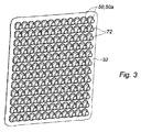
フランジ50は、有利には、医療用容器100のうちの1つのバレル102を各フランジ50に固定するように構成された固定手段を備える。図3を参照すると、固定手段は、好ましくは、案内導管72を備える。案内導管72は、開口部58から延びている。案内導管72は、開口部58内のバレル102の挿入を受容して案内するように構成され、この挿入は、フランジ50に直交する方向に起こる。案内導管72は管状であり、例えば円筒形を有する。好ましくは、案内導管72は、フランジ50の遠位面54から延びている。案内導管70は、内壁74を規定する。内壁74は、バレル102をフランジ50に固定するために固定要素76を受容するように構成された環状の凹部または溝740を備え得る。スリーブ70は、フランジ50と一体に成形することができる。
The
図6Aを参照すると、固定要素76は、溝740の表面742に塗布された接着剤であり得る。したがって、表面742は、接着剤を受容するように構成された取り付け面を形成する。結果として、バレル102は、案内導管72に接着され得る。
With reference to FIG. 6A, the fixing
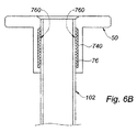
図6Bを参照すると、固定要素76は、バレル102に付着するように構成された内部摩擦嵌合面760であり得る。この摩擦嵌合面760およびバレル102は、案内導管72の残りの部分とバレル102との間の粘着係数(adhesive coefficient)よりも大きい粘着係数を有する。この摩擦嵌合面760aは、インサート、例えば、凹部または溝740の内側に収容され、熱可塑性エラストマーまたはゴムで作られているリング上に配置することができる。あるいは、摩擦嵌合面760は、共射出成形(co-injection molding)によって実現される熱可塑性エラストマーで作られていてもよい。
Referring to FIG. 6B, the fixing
図6Cを参照すると、固定要素76はスナップ機能であり得る。スナップ特徴は、バレル102の側壁に設けられた環状リブであり得る。このリブは、溝740の形状と相補的な形状を有し、バレル102をフランジ50に固定するために、溝740に挿入されるように構成される。したがって、リブおよび溝740は、バレル102をフランジ50に固定するように構成されたクリッピング要素を形成する。
With reference to FIG. 6C, the fixed
固定手段は、例えば、バレル102が完全に挿入された後、フランジ50を介したバレル102の挿入を遮断するように構成された軸方向ストップを備えていてもよい。軸方向ストップは、開口部58を区切る内縁に設けられた先細の側面64であり得る。バレル102は、バレル102が開口部58の内部に導入されたときに表面64に対して傾くように構成された先細の側面1020を備えた近位端を含み得る。
The fixing means may include, for example, an axial stop configured to block the insertion of the
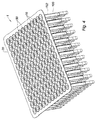
図4を参照して、保持装置1および複数の医療用容器100を含む医療用容器のパックが示されている。これらの医療用容器100は、取り外し可能な方法でネストに固定されているフランジ50に固定されている。医療用容器100は、医薬組成物のためのリザーバを画成するバレル102を有し、バレル102は、フランジ50の1つに取り付けられた近位端と、遠位先端を備えた遠位端とを有し、遠位先端は、リザーバと連通する流体通路を画成する。一実施形態では、バレル102はガラス製であり、固定手段によって対応するフランジ50に固定されている。別の実施形態では、バレル102はプラスチック材料で作られており、図6Dに示すように、フランジ50、支持構造30、および破壊可能な接続ブリッジが単一の部品で成形されている。医療用容器100はまた、遠位先端に取り付けられた針103および針を保護するキャップを含み得る。医療用容器パックは、針にオーバーモールドされ得る。さらに、プランジャストッパをバレルの内側に配置することができ、プランジャストッパは、バレル102の外側に延びているプランジャに接続されている。
With reference to FIG. 4, a pack of medical containers including the holding
本発明はまた、複数の医療用容器100の製造方法に関し、この方法は、
- 上記のように医療用容器パックを準備するステップと、
- 医療用容器100を医療用容器パックから取り外すために、フランジ50を支持構造30に固定している接続ブリッジ10を破壊するステップと、を含む。
The present invention also relates to a method for producing a plurality of
--The steps to prepare the medical container pack as described above,
-Includes a step of breaking the connecting
このステップは、好ましくは、バレル102がフランジ50に固定された後、より正確には、医薬組成物がバレル102に注がれる充填ステップの後に行われる。
This step is preferably performed after the
接続ブリッジ10を破壊するステップは、フランジ50または支持構造30に遠位または近位の力を加えることによって実現することができる。接続ブリッジ10を破壊するステップは、破壊可能な接続ブリッジ10または支持構造30に適用される切断ダイ(cutting die)によって実現され得る。
The step of breaking the connecting
医療用容器パックを準備するステップは、医療用容器100のバレル102を保持装置1のフランジ50に固定するステップを含み得る。
The step of preparing the medical container pack may include fixing the
当該方法は、固定手段によってバレル102をフランジ50に固定する前に、バレル102をフランジ50の開口部58に挿入するステップを有利に含み得る。好ましくは、バレル102はガラスで作られている。
The method may advantageously include the step of inserting the
一実施形態では、バレル102をフランジ50に固定するステップは、バレル102およびフランジ50を単一の部品に成形するステップを含む。このステップの前に、バレル102が針103上にオーバーモールドされるように、型内に針103を配置することができる。
In one embodiment, the step of fixing the
Claims (14)
複数の破壊可能な接続ブリッジ(10)と、
所定のパターンで配置され、前記医療用容器(100)のフランジを形成するように構成された複数のフランジ(50)であって、前記フランジ(50)は、前記破壊可能な接続ブリッジ(10)に接続されており、前記フランジ(50)は、前記接続ブリッジ(10)を破壊するために前記フランジに力を加えるための押圧面を形成するように構成された近位面(52)と、前記近位面(52)に対向する遠位面(54)と、を有し、前記遠位面(54)は、前記医療用容器の使用中にユーザの指が受容されるように構成されている、フランジ(50)と、
前記複数のフランジ(50)を支持するために前記破壊可能な接続ブリッジ(10)に取り付けられた板状の支持構造(30)と、を備え、
前記フランジ(50)、前記破壊可能な接続ブリッジ(10)、および前記支持構造(10)は、前記フランジ(50)が前記破壊可能な接続ブリッジ(10)および前記支持構造(30)と一体的に形成されるように、単一の部品に成形されていることを特徴とするネスト(1)。 A nest (1) for supporting a plurality of medical containers (100), wherein the nest (1) is
With multiple destructible connection bridges (10),
A plurality of flanges (50) arranged in a predetermined pattern and configured to form a flange of the medical container (100), wherein the flange (50) is a destructible connecting bridge (10). The flange (50) is connected to a proximal surface (52) configured to form a pressing surface for exerting a force on the flange to break the connecting bridge (10). It has a distal surface (54) facing the proximal surface (52), the distal surface (54) being configured to receive the user's finger during use of the medical vessel. With the flange (50)
A plate-like support structure (30) attached to the destructible connecting bridge (10) to support the plurality of flanges (50).
The flange (50), the destructible connecting bridge (10), and the support structure (10) are such that the flange (50) is integrated with the destructible connecting bridge (10) and the support structure (30). Nest (1), characterized in that it is formed into a single part so that it is formed in.
請求項12または請求項13に記載の医療用容器パックを準備するステップと、
対応する前記医療用容器(100)を前記医療用容器パックから取り外すために、前記フランジ(50)の1つを前記支持構造(30)に固定している前記接続ブリッジ(10)を破壊するステップと
を含むことを特徴とする製造方法。 A method for manufacturing a medical container (100).
The step of preparing the medical container pack according to claim 12 or 13.
A step of breaking the connecting bridge (10) fixing one of the flanges (50) to the support structure (30) in order to remove the corresponding medical container (100) from the medical container pack. A manufacturing method comprising and.
Applications Claiming Priority (3)
| Application Number | Priority Date | Filing Date | Title |
|---|---|---|---|
| EP18305547.4 | 2018-05-02 | ||
| EP18305547.4A EP3563892B1 (en) | 2018-05-02 | 2018-05-02 | A holding device for supporting a plurality of medical containers, a medical container pack comprising this holding device, and a method for manufacturing a medical container |
| PCT/EP2019/060510 WO2019211139A1 (en) | 2018-05-02 | 2019-04-24 | A nest for supporting a plurality of medical containers, a medical container pack comprising this nest, and a method for manufacturing a medical container |
Publications (1)
| Publication Number | Publication Date |
|---|---|
| JP2021522017A true JP2021522017A (en) | 2021-08-30 |
Family
ID=62143092
Family Applications (1)
| Application Number | Title | Priority Date | Filing Date |
|---|---|---|---|
| JP2020561675A Pending JP2021522017A (en) | 2018-05-02 | 2019-04-24 | Nests for supporting multiple medical containers, medical container packs containing this nest, and methods for manufacturing medical containers. |
Country Status (6)
| Country | Link |
|---|---|
| US (1) | US11931542B2 (en) |
| EP (1) | EP3563892B1 (en) |
| JP (1) | JP2021522017A (en) |
| CN (1) | CN112074309B (en) |
| ES (1) | ES2982563T3 (en) |
| WO (1) | WO2019211139A1 (en) |
Families Citing this family (4)
| Publication number | Priority date | Publication date | Assignee | Title |
|---|---|---|---|---|
| CN111977135A (en) * | 2020-07-03 | 2020-11-24 | 洪瑞 | Container subassembly is placed to syringe of adjustable size |
| FR3114081B1 (en) * | 2020-09-11 | 2022-08-19 | A Raymond Et Cie | DELIVERY TRAY AND PACKAGING SYSTEM FOR MEDICAL ITEMS |
| MX2022005952A (en) * | 2021-05-18 | 2023-04-10 | Gerresheimer Glas Gmbh | Transporting packaging units. |
| USD1119282S1 (en) * | 2024-04-15 | 2026-03-24 | Schott Pharma Schweiz Ag | Portion of a holding structure for pharmaceutical containers |
Citations (9)
| Publication number | Priority date | Publication date | Assignee | Title |
|---|---|---|---|---|
| JPH06261946A (en) * | 1993-03-12 | 1994-09-20 | Nissho Corp | Chemical-filled syringe |
| US5372590A (en) * | 1990-07-27 | 1994-12-13 | Habley Medical Technology Corporation | Multi-celled safety package, needle guard and safety disposal module with sleeve for prefilled medication cartridges |
| WO2012035909A1 (en) * | 2010-09-15 | 2012-03-22 | 株式会社バンダイ | Parts supply component |
| JP2012100927A (en) * | 2010-11-11 | 2012-05-31 | Arte Corp | Packaging plate, syringe-holding container, and method of manufacturing combined container-syringe |
| US20120180286A1 (en) * | 2011-01-17 | 2012-07-19 | Stafast Products, Inc. | Apparatus and method for severing and inserting collated t-nuts |
| JP2013538627A (en) * | 2010-09-28 | 2013-10-17 | ベクトン ディキンソン フランス | Packaging for cylindrical containers |
| US20130313143A1 (en) * | 2010-09-30 | 2013-11-28 | Covidien Lp | Syringe Assembly and Package for Distribution of Same |
| JP2016059635A (en) * | 2014-09-18 | 2016-04-25 | キョーラク株式会社 | Prefilled syringe |
| WO2016157909A1 (en) * | 2015-03-31 | 2016-10-06 | ホヤ レンズ タイランド リミテッド | Method for manufacturing functional plastic lens and polarizing plastic lens |
Family Cites Families (18)
| Publication number | Priority date | Publication date | Assignee | Title |
|---|---|---|---|---|
| US2510091A (en) * | 1947-08-26 | 1950-06-06 | Floyd J Dofsen | Method of severing sprues from a molded part and simultaneously molding a second plastic to the part |
| GB967302A (en) * | 1960-07-28 | 1964-08-19 | Gillette Industries Ltd | Improvements in packaging |
| US3921633A (en) * | 1974-05-06 | 1975-11-25 | Survival Technology | Finger grip device |
| FR2614658B1 (en) * | 1987-04-30 | 1989-06-30 | Vinel Roger | ASSEMBLY OF ANCHORS OF ANCHOR IN PLASTIC MATERIAL CONDITIONED IN CLUSTER |
| AU8945191A (en) * | 1990-10-12 | 1992-05-20 | Habley Medical Technology Corporation | Disposal module with sleeve for prefilled cartridges |
| JP4038042B2 (en) * | 2001-12-10 | 2008-01-23 | 三甲株式会社 | Plastic pallet |
| RU36820U1 (en) * | 2003-12-29 | 2004-03-27 | Свиридов Михаил Александрович | CARRYING PALLET FOR GROUP PACKAGING GLASSES |
| CN101652152B (en) * | 2007-03-05 | 2013-03-20 | 株式会社大协精工 | Medical container |
| EP2072071A1 (en) * | 2007-12-18 | 2009-06-24 | Sybermat | Syringe nest lid |
| EP2737952B1 (en) * | 2009-08-10 | 2016-01-13 | West Pharmaceutical Services, Inc. | Method for filling flangeless containers |
| EP2476448A1 (en) * | 2011-01-12 | 2012-07-18 | Becton Dickinson France S.A.S | Packaging for containers |
| DE102012103898A1 (en) * | 2012-05-03 | 2013-11-07 | Schott Ag | Supporting structure for simultaneously holding a plurality of medical or pharmaceutical containers and transport or packaging container with self |
| JP5081330B1 (en) * | 2012-06-20 | 2012-11-28 | 株式会社アルテ | Syringe manufacturing cartridge set and two-chamber container-use syringe manufacturing method |
| ITVI20120215A1 (en) * | 2012-08-30 | 2014-03-01 | Fedegari Autoclavi | STRUCTURE FOR PACKAGING COMPONENTS FOR PHARMACEUTICAL CONTAINERS |
| DE102013111600B4 (en) * | 2013-10-21 | 2018-04-05 | Schott Ag | Support structure for holding containers for substances for medical, pharmaceutical or cosmetic applications, as well as transport and packaging containers with the same |
| EP3028947A1 (en) * | 2014-12-05 | 2016-06-08 | F. Hoffmann-La Roche AG | Closing a chamber of a container for a pharmaceutical product |
| AU2015391635B2 (en) * | 2015-04-17 | 2019-05-16 | Schott Kaisha Pvt Ltd | Supporting structure for sealed cartridges, transport or packaging container and process |
| WO2018020505A1 (en) * | 2016-07-27 | 2018-02-01 | Schott Kaisha Pvt. Ltd. | Method for closing vials, supporting structure for vial stopper members and transport or packaging container |
-
2018
- 2018-05-02 EP EP18305547.4A patent/EP3563892B1/en active Active
- 2018-05-02 ES ES18305547T patent/ES2982563T3/en active Active
-
2019
- 2019-04-24 CN CN201980029555.XA patent/CN112074309B/en active Active
- 2019-04-24 JP JP2020561675A patent/JP2021522017A/en active Pending
- 2019-04-24 WO PCT/EP2019/060510 patent/WO2019211139A1/en not_active Ceased
- 2019-04-24 US US17/051,902 patent/US11931542B2/en active Active
Patent Citations (9)
| Publication number | Priority date | Publication date | Assignee | Title |
|---|---|---|---|---|
| US5372590A (en) * | 1990-07-27 | 1994-12-13 | Habley Medical Technology Corporation | Multi-celled safety package, needle guard and safety disposal module with sleeve for prefilled medication cartridges |
| JPH06261946A (en) * | 1993-03-12 | 1994-09-20 | Nissho Corp | Chemical-filled syringe |
| WO2012035909A1 (en) * | 2010-09-15 | 2012-03-22 | 株式会社バンダイ | Parts supply component |
| JP2013538627A (en) * | 2010-09-28 | 2013-10-17 | ベクトン ディキンソン フランス | Packaging for cylindrical containers |
| US20130313143A1 (en) * | 2010-09-30 | 2013-11-28 | Covidien Lp | Syringe Assembly and Package for Distribution of Same |
| JP2012100927A (en) * | 2010-11-11 | 2012-05-31 | Arte Corp | Packaging plate, syringe-holding container, and method of manufacturing combined container-syringe |
| US20120180286A1 (en) * | 2011-01-17 | 2012-07-19 | Stafast Products, Inc. | Apparatus and method for severing and inserting collated t-nuts |
| JP2016059635A (en) * | 2014-09-18 | 2016-04-25 | キョーラク株式会社 | Prefilled syringe |
| WO2016157909A1 (en) * | 2015-03-31 | 2016-10-06 | ホヤ レンズ タイランド リミテッド | Method for manufacturing functional plastic lens and polarizing plastic lens |
Also Published As
| Publication number | Publication date |
|---|---|
| EP3563892C0 (en) | 2024-03-13 |
| CN112074309A (en) | 2020-12-11 |
| EP3563892B1 (en) | 2024-03-13 |
| ES2982563T3 (en) | 2024-10-16 |
| US11931542B2 (en) | 2024-03-19 |
| WO2019211139A1 (en) | 2019-11-07 |
| CN112074309B (en) | 2022-11-11 |
| US20210106749A1 (en) | 2021-04-15 |
| EP3563892A1 (en) | 2019-11-06 |
Similar Documents
| Publication | Publication Date | Title |
|---|---|---|
| CN110481984B (en) | Support structure for simultaneously supporting a plurality of containers and transport structure comprising same | |
| US11286095B2 (en) | Supporting structure for concurrently supporting a plurality of containers for substances for pharmaceutical, medical or cosmetic applications, transport structure and transport or packaging container comprising the same | |
| JP2021522017A (en) | Nests for supporting multiple medical containers, medical container packs containing this nest, and methods for manufacturing medical containers. | |
| US12364806B2 (en) | Holding device configured to support a plurality of medical containers such as syringes | |
| US11464705B2 (en) | Holding structure for concurrently holding a plurality of containers for substances for pharmaceutical, medical or cosmetic applications, transport structure and transport or packaging container comprising the same | |
| US20250177253A1 (en) | Holding Device for Medical Containers With Plates of Different Elevations | |
| JP7843291B2 (en) | Packing nests with stacking pins and plunger stoppers to ensure reliable alignment of nest stacks (PILE) | |
| CN117062755B (en) | Insert and cartridge device | |
| CN117120121A (en) | Nesting sets for packaging plunger stops with integrated stacking features that ensure reliable alignment of a stack of nesting sets | |
| US20250161556A1 (en) | Holding Device for Medical Containers With Reinforcing Ribs for Increasing Stiffness and Reducing Deflection | |
| EP4516334A1 (en) | Medical container nest with reduced warpage and residual stress |
Legal Events
| Date | Code | Title | Description |
|---|---|---|---|
| A621 | Written request for application examination |
Free format text: JAPANESE INTERMEDIATE CODE: A621 Effective date: 20220420 |
|
| A977 | Report on retrieval |
Free format text: JAPANESE INTERMEDIATE CODE: A971007 Effective date: 20230306 |
|
| A131 | Notification of reasons for refusal |
Free format text: JAPANESE INTERMEDIATE CODE: A131 Effective date: 20230314 |
|
| A521 | Request for written amendment filed |
Free format text: JAPANESE INTERMEDIATE CODE: A523 Effective date: 20230614 |
|
| A131 | Notification of reasons for refusal |
Free format text: JAPANESE INTERMEDIATE CODE: A131 Effective date: 20231003 |
|
| A601 | Written request for extension of time |
Free format text: JAPANESE INTERMEDIATE CODE: A601 Effective date: 20231222 |
|
| A02 | Decision of refusal |
Free format text: JAPANESE INTERMEDIATE CODE: A02 Effective date: 20240319 |
|
| A521 | Request for written amendment filed |
Free format text: JAPANESE INTERMEDIATE CODE: A523 Effective date: 20240719 |
|
| A911 | Transfer to examiner for re-examination before appeal (zenchi) |
Free format text: JAPANESE INTERMEDIATE CODE: A911 Effective date: 20240730 |
|
| A912 | Re-examination (zenchi) completed and case transferred to appeal board |
Free format text: JAPANESE INTERMEDIATE CODE: A912 Effective date: 20240816 |
|
| A521 | Request for written amendment filed |
Free format text: JAPANESE INTERMEDIATE CODE: A523 Effective date: 20260209 |