JP2022001990A - Sales data processing equipment - Google Patents
Sales data processing equipment Download PDFInfo
- Publication number
- JP2022001990A JP2022001990A JP2020106322A JP2020106322A JP2022001990A JP 2022001990 A JP2022001990 A JP 2022001990A JP 2020106322 A JP2020106322 A JP 2020106322A JP 2020106322 A JP2020106322 A JP 2020106322A JP 2022001990 A JP2022001990 A JP 2022001990A
- Authority
- JP
- Japan
- Prior art keywords
- sales data
- data processing
- payment terminal
- processing device
- main body
- Prior art date
- Legal status (The legal status is an assumption and is not a legal conclusion. Google has not performed a legal analysis and makes no representation as to the accuracy of the status listed.)
- Granted
Links
Images


Landscapes
- Cash Registers Or Receiving Machines (AREA)
Abstract
Description
本発明の実施形態は、販売データ処理装置に関する。 Embodiments of the present invention relate to a sales data processing apparatus.
従来、商品登録を店員(キャッシャ)が行う通常のPOS(Point of Sales)端末としての使用形態と、購入者自身が商品登録するセルフPOS端末としての使用形態と、の両方に対応した販売データ処理装置がある。そのような販売データ処理装置は、各使用形態に適したモードを備え、いずれかのモードが選択されて稼働する。上述のような販売データ処理装置は、キャッシャの立ち位置と客用通路との間に位置するチェックアウトカウンタ上に、使用形態に応じた向きに表示部や操作部を向けて、設置される。 Conventionally, sales data processing corresponding to both the usage form as a normal POS (Point of Sales) terminal in which a store clerk (casher) registers a product and the usage pattern as a self-POS terminal in which a purchaser himself registers a product. There is a device. Such a sales data processing device includes a mode suitable for each usage pattern, and one of the modes is selected and operated. The sales data processing device as described above is installed on a checkout counter located between the standing position of the cashier and the aisle for customers, with the display unit and the operation unit facing in the direction according to the usage pattern.
ここで、近年は、販売データ処理装置に、決済端末が接続されていることが多い。決済端末は、クレジットカードや電子マネーを用いるキャッシュレス決済を行うための装置である。決済端末は、従来、チェックアウトカウンタ上に直接置かれたり、或いは、チェックアウトカウンタに取り付けられた支持台に置かれたりしており、販売データ処理装置と一体化されていない(例えば特許文献1)。 Here, in recent years, a payment terminal is often connected to a sales data processing device. A payment terminal is a device for performing cashless payment using a credit card or electronic money. Conventionally, the payment terminal is placed directly on the checkout counter or placed on a support base attached to the checkout counter, and is not integrated with the sales data processing device (for example, Patent Document 1). ).
設置やメンテナンス、使い勝手等の都合から、POS端末と決済端末との一体化が望まれている。しかしながら、単に一体化されただけであると、セルフPOS端末としての使用形態と通常のPOS端末としての使用形態とを入れ替える際に、決済端末を購入者に向けたままで販売データ処理装置の向きを変えることができなくなり、不都合である。 For convenience of installation, maintenance, usability, etc., it is desired to integrate the POS terminal and the payment terminal. However, if it is simply integrated, when the usage pattern as a self-POS terminal and the usage pattern as a normal POS terminal are exchanged, the orientation of the sales data processing device is changed while the payment terminal is directed toward the purchaser. It is inconvenient because it cannot be changed.
本発明が解決しようとする課題は、決済端末の使い勝手を損なわずに一体化可能にした販売データ処理装置を提供することである。 An object to be solved by the present invention is to provide a sales data processing device that can be integrated without impairing the usability of the payment terminal.
実施形態の販売データ処理装置は、商品を登録する操作を店員が行う第1の使用形態と、前記操作を購入者が行う第2の使用形態と、に変更可能なものであって、表示部と、本体部と、操作部と、ブラケットと、を備える。表示部は、操作者向けの情報を表示する。本体部は、表示部を支持する。操作部は、本体部および表示部の少なくともいずれかに一体的に設けられ、操作者から、少なくとも前記操作を受け付ける。ブラケットは、登録された商品の決済を行うための決済端末を、その前後および上下が入れ替わる回転を可能にするための、交差またはねじれの位置に位置する二本の回転軸を含んで構成されて、本体部の側面に取り付けられている。 The sales data processing device of the embodiment can be changed into a first usage mode in which the store clerk performs the operation of registering the product and a second usage mode in which the purchaser performs the operation, and is a display unit. , A main body, an operation unit, and a bracket. The display unit displays information for the operator. The main body supports the display. The operation unit is integrally provided in at least one of the main body unit and the display unit, and receives at least the operation from the operator. The bracket consists of a payment terminal for making payments for registered goods, including two axes of rotation located at crossed or twisted positions to allow for alternating front-back and up-down rotations. , It is attached to the side of the main body.
以下、販売データ処理装置100の実施の一形態について説明する。本実施形態の販売データ処理装置100は、第1および第2の、2つの使用形態に対応するものである。第1の使用形態は、売る商品の登録を店員(キャッシャ)が行う第1モードとしてPOS端末を稼働させる形態である。第2の使用形態は、購入者が自身で買う商品の登録を行う第2モードとしてPOS端末を稼働させる形態である。第1モード稼働時のPOS端末を通常のPOS端末とし、第2モード稼働時のPOS端末をセルフPOS端末と称する。
Hereinafter, an embodiment of the sales
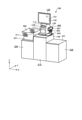
図1は、実施形態において、セルフPOS端末として使用中の販売データ処理装置100の外観および設置状態の一例を概略的に示した斜視図である。図2は、キャッシャが操作する通常のPOS端末として使用中の販売データ処理装置100の外観および設置状態の一例を概略的に示した斜視図である。
FIG. 1 is a perspective view schematically showing an example of the appearance and installation state of the sales
以下の説明において、X軸、Y軸、及びZ軸から構成される直交座標系を用いる。図中、矢印の指し示す方向が正方向である。X軸方向は、販売データ処理装置100の幅方向(或いは図中左右方向)である。また、Y軸方向は、奥行方向であって、図中手前から奥に向かう方向が正方向である。また、Z軸方向は、販売データ処理装置100の高さ方向(或いは上下方向)であって、Z軸正方向が上方向であり、Z軸負方向が下方向である。
In the following description, a Cartesian coordinate system composed of X-axis, Y-axis, and Z-axis will be used. In the figure, the direction indicated by the arrow is the positive direction. The X-axis direction is the width direction (or the left-right direction in the figure) of the sales
販売データ処理装置100は、本体部110、タッチパネル付きディスプレイ120、ブラケット130および回転台140を備えている。販売データ処理装置100は、台210の上面211に載置される。台210の両脇には、一対の台220,230が設けられる。台220は、買い物かご300を載置するためのものである。台230は、例えば、登録済みの商品の袋詰めを行う場として提供されている。
The sales
台220,230の上面221,231の高さは、台210の上面211の高さよりも低い。上面221,231と上面211との高低差は、台220上の買い物かご300の縁から台210の上面211までの高低差を緩和する程度の値に設定される。
The height of the upper surfaces 221,231 of the
ここで、図2における台210の手前側が客用通路であって、台210の奥側がキャッシャの立ち位置である。図1においても、セルフPOS端末としての販売データ処理装置100の操作者である客の通路は、台210の図中手前である。したがって、客用通路は、販売データ処理装置100の使用形態の変更に関わらず、固定である。
Here, the front side of the table 210 in FIG. 2 is the passenger passage, and the back side of the table 210 is the standing position of the cashier. Also in FIG. 1, the passage of the customer who is the operator of the sales
本体部110は、制御部、読取部111、印字部112などを、内蔵している。また、本体部110は、タッチパネル付きディスプレイ120を支持している。
The
タッチパネル付きディスプレイ120は、液晶パネル121およびタッチパネル122を備えている。液晶パネル121は、表示部の一例であって、操作者向けの情報を、文字や画像などによって表示する。タッチパネル122は、操作部の一例であって、操作者から、商品登録や決済などに関する操作を受け付ける。制御部は、販売データ処理装置100の各部(タッチパネル付きディスプレイ120、読取部111、印字部112など)を制御するとともに、商品登録や決済などの販売データ処理を行う。
The
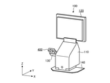
ブラケット130は、決済端末400を、支持する。決済端末400は、販売データ処理装置100と協働して商品の代金の決済処理を行う装置である。
The
決済端末400は、表示部401、キーパッド402、カード挿入口403を備えている。表示部401は、例えば液晶ディスプレイであって、客向けの情報を表示する。キーパッド402は、例えば0〜9の数字の入力を受け付けるものであって、暗証番号等の入力を受け付ける。カード挿入口403は、クレジットカード等の挿入を受け付ける。決済端末400は、販売データ処理装置100から取得した支払金額を表示部401に表示し、カード挿入口403から挿し込まれたクレジットカード等の情報を内蔵のリーダで読み取り、暗証番号の入力をキーパッド402により受け付ける。これにより、決済端末400は、販売データ処理装置100と協働して、商品代金のクレジット決済等を行う。
The
ここで、決済端末400の各面のうち、決済を行う操作者(客)に向けられるのは、表示部401およびキーパッド402が設けられた面であるので、以下の説明においては、表示部401およびキーパッド402が設けられた面を、決済端末400の正面とする。
Here, among the faces of the
また、決済端末400は、第1、第2いずれの使用形態においても客に操作されるので、いずれの使用形態においても客用通路側に正面を向けて設置される。なお、ブラケット130は、第2の使用形態において本体部110の両側面のうち客から見て右側となる方の側面(即ち第2の使用形態における本体部110の右側面)に、取り付けられている。
Further, since the
回転台140は、販売データ処理装置100の向きを変更自在するためのものであって、販売データ処理装置100の前後方向を逆にする回転を可能にする。このために回転台140は、本体部110やその上に取り付けられたタッチパネル付きディスプレイ120を、販売データ処理装置100の高さ方向を軸に回転自在に支持する。
The
図3は、本体部110の内部構造を示すための概略的な縦断側面図である。読取部111は、操作部の一例であって、読取窓501およびスキャナ502を備えている。読取窓501は、本体部110の筐体の一部を構成する。
FIG. 3 is a schematic vertical sectional side view for showing the internal structure of the
スキャナ502は、読取窓501越しに、商品に付されたシンボルを読み取る。ここでシンボルとは、例えばバーコードや二次元コードなどの画像で示されるコードであって、例えば商品コードなどの商品の特定を可能にする情報を記録したものである。スキャナ502は、赤外線により読み取るものでもよいし、或いは、例えばイメージセンサであってもよい。
The
印字部112は、ロール支持部503、印字ヘッド504、プラテンローラ505、排紙口506を備えている。ロール支持部503は、帯状の紙が巻かれたものであるロール紙を、回転自在に支持する。ロール紙は、紙の引き出しに対応して回転する。
The
プラテンローラ505は、モータ等の駆動力により回転して、印字ヘッド504との間に挟み持った紙を引き出し、搬送する。印字ヘッド504は、例えばサーマルヘッドであって、紙のプラテンローラ505との間に挟んだ部分に、印字を施す。サーマルヘッドは、整列して配置された微小な発熱体を備え、当該発熱体に対して、画像データに応じた通電を行うことにより、画像形成を行う。排紙口506は、印字後の紙が排出される開口である。
The
ここで、販売データ処理装置100の読取窓501および排紙口506は、商品の登録を行う操作者(通常のPOS端末として使用中であればキャッシャ、セルフPOS端末として使用中であれば客自身)の立ち位置に向けられるものである。よって、以下の説明においては、読取窓501および排紙口506が設けられている側を、販売データ処理装置100の正面側とする。図1は、販売データ処理装置100の正面側が客用通路に面した形態を示し、図2は、販売データ処理装置100の背面側が客用通路に面した形態を示す。
Here, the reading
図4は、回転台140の外観を示す斜視図である。回転台140は、第1板金141、第2板金142、第3板金143、軸144を備えている。第1板金141は、台210の上面211に、ねじ止め等により固定される。第2板金142には、販売データ処理装置100の底面が、ねじ止め等により固定される。軸144は、第2板金142に対して回転自在であって、第2板金142を第1板金141に対して回転自在に支持する。第3板金143は、第1板金141と第2板金142との間に位置するスペーサであって、第1板金141に対する第2板金142の回転による摩擦を低減して回転を容易にする。
FIG. 4 is a perspective view showing the appearance of the rotary table 140. The rotary table 140 includes a
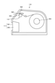
図5は、販売データ処理装置100を台210上で回転させて、図1に示すセルフPOS端末としての使用状態から、販売データ処理装置100の背面側を客用通路に向けた状態(前後逆にした状態)を示す斜視図である。このときの回転は、回転台140によるものであって、回転の軸はZ軸方向に平行である。また、この回転により、決済端末400の表示部401やキーパッド402は、客立ち位置側からキャッシャ立ち位置側に向く。
FIG. 5 shows a state in which the sales
さらに、図6は、決済端末400を、図5に示す状態からX軸周りに回転させて表示部401やキーパッド402を客用通路側に向けた状態を示す斜視図である。このときの回転は、ブラケット130によるものであって、回転の軸はX軸方向に平行である。この回転により、決済端末400の表示部401やキーパッド402は客用通路側を向いたが、この状態では上下が逆である。
Further, FIG. 6 is a perspective view showing a state in which the
そして、この図6に示す状態から、上下が逆になるように決済端末400をさらに回転させると、図2に示す、キャッシャが操作する通常のPOS端末としての使用状態となる。このときの回転は、ブラケット130が備えるもう一つの回転軸によるものであって、この回転軸は決済端末400の厚さ方向(次に図7により説明するZ´軸方向)に平行である。
Then, when the
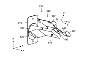
図7は、ブラケット130の外観を示す斜視図である。この状態は、図1に示す状態に対応する。ここで、X軸、Y軸およびZ軸で示す直交座標系とは別の、X´軸、Y´軸およびZ´軸で構成される第2の直交座標系を、二点鎖線で示す。
FIG. 7 is a perspective view showing the appearance of the
本実施形態における決済端末400としては、図1等に示すような、縦長で薄い直方体のような形状を有するものを想定している。Z´軸は、決済端末400の厚さ方向を示す。X´軸は、決済端末400の幅方向を示す。Y´軸は、決済端末400の縦方向を示す。なお、図7において、X軸とX´軸とは平行である。
As the
ブラケット130は、側板610、回転支持部620、アーム部630および端末保持部640を、備えている。端末保持部640は、決済端末400を背面から把持する形状に形成されており、平面部641、押さえ部642、切欠き部643および逃がし孔644を備えている。
The
平面部641は、決済端末400の背面に沿う。押さえ部642は、平面部641の四隅から突出し、決済端末400の側面を押さえる。切欠き部643は、決済端末400の着脱時に把持しやすいよう決済端末400の側辺部を露出させる。逃がし孔644は、決済端末400の背面に設けられたゴム脚を逃がすものである。
The
側板610は、販売データ処理装置100の本体部110の左右両側面のいずれかに、取り付けられる。本実施形態では、図1に示すセルフPOS端末としての使用状態において、本体部110の両側面のうち、操作者である客から見て右側になる方の側面に、取り付けられている。
The
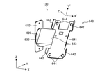
回転支持部620は、側板610に対してアーム部630を回転自在に連結する。当該回転は、X軸方向に平行な軸周りの回転である。ここで、図8は、アーム部630を図7に示す状態からX軸周りに回転させた状態を示す斜視図である。
The
また、回転支持部620は、回転止めのための構成を含んでいる。回転止めのための構成は、例えば、ワッシャーやナットを用いた周知の構成である。回転止めのための構成は、ここでの回転に、所望の摩擦力を付与する。当該摩擦力の最低限の大きさは、ブラケット130が支持する決済端末400が決済処理のための操作を受けた程度では回転しない程度である。また、同摩擦力は、大きくても、アーム部630を軸に回転させる方向の力を端末保持部640に与えた場合に、回転が可能な程度である。
Further, the
アーム部630は、側板610および回転支持部620から、X軸方向に沿って突出していて、X軸方向に平行な軸周りの回転が自在であるように、回転支持部620によって側板610に連結されている。端末保持部640は、自身の厚さ方向となるZ´軸方向に平行な軸周りの回転が自在であるように、アーム部630の先端部に取り付けられている。
The
図8に示すように、端末保持部640は、スペーサ645および回転軸646を、さらに備えている。スペーサ645は薄い箱あるいは枠のような形状を有するパーツであって、平面部641の背面側に固定されてアーム部630との間に介在し、両者間に所定の隙間を形成する。
As shown in FIG. 8, the
回転軸646は、Z´軸に平行な軸であって、アーム部630に対してスペーサ645を回転自在に連結する。これにより、端末保持部640は、アーム部630に対し、Z´軸周りの回転が自在となる。
The
上述のように、ブラケット130は、ねじれの位置に位置する(或いは交差する)二本の回転軸(即ち回転軸646および回転支持部650の回転軸)を含んで構成され、これにより、決済端末400を、その前後ろおよび上下が入れ替わる回転を可能にする。
As mentioned above, the
ここで、決済端末400を、上記二本の軸周りに回転自在にするための、寸法設定の一例について述べる。
Here, an example of dimensional setting for making the
アーム部630の最低限の長さは、端末保持部640に把持された決済端末400が厚さ方向を軸に回転可能な程度である。つまり、アーム部630の長さは、決済端末400の回転の中心(回転軸646)から決済端末400の外周までの距離の最大値よりも大きい。
The minimum length of the
アーム部630の長さの具体的な値は、決済端末400と回転軸646とのX´Y´平面における位置関係に応じて設定される。例えば、決済端末400の幅方向中央であって上下方向中央である位置に回転軸646が位置するならば、アーム部630の長さは、決済端末400の中心から四隅までの距離以上である。
The specific value of the length of the
また、ブラケット130は、決済端末400の下端部を、本体部110の底面よりも高い位置に位置させる。このために、ブラケット130は、本体部110の底面からの高さが、決済端末400の回転の中心(回転軸646)から決済端末400の外周までの距離の最大値よりも大きくなる位置で、決済端末400を支持する。
Further, the
ブラケット130による決済端末400の保持高さの具体的な寸法は、上記例同様、決済端末400と回転軸646とのX´Y´平面における位置関係に応じて設定される。例えば、上記例と同様に、決済端末400の幅方向中央であって上下方向中央である位置に回転軸646が位置するならば、回転軸646から本体部110の底面までの距離は、決済端末400の長さ(上下方向寸法)の半分以上、というように設定可能である。ただし、設定にあたっては、決済端末400が台210の上面211に対して斜めになるように位置固定されて用いられることと、決済端末400の下端部のカード挿入口403にクレジットカードを挿入可能にするための空間を設けることと、をさらに考え合わせることが好適である。
The specific dimension of the holding height of the
なお、アーム部630およびスペーサ645は中空の部材であって、決済端末400と販売データ処理装置100とを接続するケーブルの通路として利用される。
The
このような構成において、第1の使用形態における通常のPOS端末としての販売データ処理装置100(図2参照)は、読取部111やタッチパネル122でキャッシャの操作を受け付けることにより、商品の登録を行う。登録された商品の決済処理は、決済端末400により行われる。販売データ処理装置100は、決済端末400に、商品の代金である支払金額を送信する。決済端末400は、販売データ処理装置100から受信した支払金額を表示部401に表示し、カード挿入口403から挿し込まれたクレジットカード等の情報を内蔵のリーダで読み取り、客による暗証番号の入力操作をキーパッド402により受け付ける。これにより、決済端末400は、販売データ処理装置100と協働して、商品代金のクレジット決済等を行う。
In such a configuration, the sales data processing device 100 (see FIG. 2) as a normal POS terminal in the first usage mode registers a product by receiving an operation of a cashier on the
また、第2の使用形態におけるセルフPOS端末としての販売データ処理装置100(図1参照)は、読取部111やタッチパネル122で客自身の操作を受け付けることにより、商品の登録を行う。登録された商品の決済処理は、決済端末400により行われる。販売データ処理装置100は、決済端末400に、商品の代金である支払金額を送信する。決済端末400は、販売データ処理装置100から受信した支払金額を表示部401に表示し、カード挿入口403から挿し込まれたクレジットカード等の情報を内蔵のリーダで読み取り、客による暗証番号の入力操作をキーパッド402により受け付ける。これにより、決済端末400は、販売データ処理装置100と協働して、商品代金のクレジット決済等を行う。
Further, the sales data processing device 100 (see FIG. 1) as a self-POS terminal in the second usage mode registers a product by receiving an operation of the customer himself / herself by the
販売データ処理装置100の使用形態を変更する様子について、以下に説明する。例えば、セルフPOS端末として使用していた販売データ処理装置100(図1参照)を、通常のPOS端末として使用する(図2参照)には、まず、販売データ処理装置100の前後が逆になるよう、回転台140によりZ軸周りに回転させる。
The state of changing the usage pattern of the sales
これにより、販売データ処理装置100は、図5に示す状態となる。この状態においては、決済端末400は、キャッシャ立ち位置側を向いていて、客による操作を受けられる状態にない。そこで次に、決済端末400をアーム部630ごとX軸周りに回転させる。
As a result, the sales
これにより販売データ処理装置100は、図6に示す状態となる。この状態においては、決済端末400は、上下が逆になっており、操作を受け付けられる状態に至っていない。そこで次に、決済端末400を、その厚さ方向であるZ´軸周りに回転させる。これにより、決済端末400は、図2に示す、客からの操作を受け付け可能な状態になる。
As a result, the sales
以上のように、実施形態によれば、決済端末400を販売データ処理装置100に一体化可能にするとともに、二つの使用形態に応じて、決済端末400を取り外さなくともその向きを容易に変更することが可能である。即ち本実施形態によれば、決済端末400の使い勝手を損なわずに一体化可能にした販売データ処理装置100を提供することができる。
As described above, according to the embodiment, the
なお、上記実施形態では、現金を取り扱う決済について述べていないが、現金の取り扱いは、販売データ処理装置100と接続する周知の釣銭機やドロワ或いは金庫を台210等に設置することにより、可能である。
Although the payment for handling cash is not described in the above embodiment, the handling of cash is possible by installing a well-known change machine, drawer or safe connected to the sales
また、実施にあたっては、ブラケット130を、本体部110の両側面に選択的に取り付け可能な構成としてもよい。これにより、店舗の方針などに応じて決済端末400の位置を選択することが可能となる。
Further, in the implementation, the
本発明のいくつかの実施形態を説明したが、これらの実施形態は、例として提示したものであり、発明の範囲を限定することは意図していない。これら新規な実施形態は、その他の様々な形態で実施されることが可能であり、発明の要旨を逸脱しない範囲で、種々の省略、置き換え、変更を行うことができる。これら実施形態やその変形は、発明の範囲や要旨に含まれるとともに、特許請求の範囲に記載された発明とその均等の範囲に含まれる。 Although some embodiments of the present invention have been described, these embodiments are presented as examples and are not intended to limit the scope of the invention. These novel embodiments can be implemented in various other embodiments, and various omissions, replacements, and changes can be made without departing from the gist of the invention. These embodiments and modifications thereof are included in the scope and gist of the invention, and are also included in the scope of the invention described in the claims and the equivalent scope thereof.
100…販売データ処理装置
110…本体部、111…読取部(操作部の一例)、112…印字部
120…タッチパネル付きディスプレイ
121…液晶パネル(表示部の一例)、122…タッチパネル(操作部の一例)
130…ブラケット
140…回転台、141〜143…第1〜第3板金、144…軸
210…台、211…上面
220…台、221…上面
230…台、231…上面
300…買い物かご
400…決済端末、401…表示部、402…キーパッド、403…カード挿入口
501…読取窓、502…スキャナ、503…ロール支持部、
504…印字ヘッド、505…プラテンローラ、506…排紙口
610…側板、620…回転支持部、630…アーム部、640…端末保持部
641…平面部、642…押さえ部、643…切欠き部、644…逃がし孔、
645…スペーサ、646…回転軸、650…回転支持部
100 ... Sales
130 ...
504 ... Print head, 505 ... Platen roller, 506 ...
645 ... Spacer, 646 ... Rotating shaft, 650 ... Rotating support
Claims (5)
操作者向けの情報を表示する表示部と、
前記表示部を支持する本体部と、
前記本体部および前記表示部の少なくともいずれかに一体的に設けられ、操作者から、少なくとも前記操作を受け付ける操作部と、
登録された商品の決済を行うための決済端末を、その前後および上下が入れ替わる回転を可能にするための、交差またはねじれの位置に位置する二本の回転軸を含んで構成されて、前記本体部の側面に取り付けられたブラケットと、
を備える販売データ処理装置。 It is a sales data processing device that can be changed to a first usage mode in which a store clerk performs an operation for registering a product and a second usage mode in which the purchaser performs the operation.
A display unit that displays information for the operator, and
The main body that supports the display and
An operation unit provided integrally with at least one of the main body unit and the display unit and receiving at least the operation from the operator.
A payment terminal for making payments for registered goods is configured to include two rotation axes located at crossed or twisted positions to allow the front-back and top-bottom rotations of the main body. With the bracket attached to the side of the part,
A sales data processing device equipped with.
請求項1に記載の販売データ処理装置。 The sales data processing device according to claim 1, wherein the bracket is attached to the right side surface of the main body portion in the second usage mode.
請求項1または2に記載の販売データ処理装置。 The sales data processing device according to claim 1 or 2, wherein the bracket positions the lower end portion of the payment terminal at a position higher than the bottom surface of the main body portion.
請求項1〜3のいずれか1つに記載の販売データ処理装置。 Claims 1 to support the payment terminal at a position where the height of the bracket from the bottom surface of the main body is larger than the maximum value of the distance from the rotation center of the payment terminal to the outer periphery of the payment terminal. The sales data processing device according to any one of 3.
をさらに備える、請求項1〜4のいずれか1つに記載の販売データ処理装置。 The invention according to any one of claims 1 to 4, which is attached to the bottom surface of the main body portion, enables rotation of the main body portion in the reverse direction, and further includes a rotary table for supporting the main body portion. Sales data processing equipment.
Priority Applications (2)
| Application Number | Priority Date | Filing Date | Title |
|---|---|---|---|
| JP2020106322A JP7438861B2 (en) | 2020-06-19 | 2020-06-19 | sales data processing equipment |
| JP2024019235A JP2024045501A (en) | 2020-06-19 | 2024-02-13 | Sales data processor and mounting member |
Applications Claiming Priority (1)
| Application Number | Priority Date | Filing Date | Title |
|---|---|---|---|
| JP2020106322A JP7438861B2 (en) | 2020-06-19 | 2020-06-19 | sales data processing equipment |
Related Child Applications (1)
| Application Number | Title | Priority Date | Filing Date |
|---|---|---|---|
| JP2024019235A Division JP2024045501A (en) | 2020-06-19 | 2024-02-13 | Sales data processor and mounting member |
Publications (2)
| Publication Number | Publication Date |
|---|---|
| JP2022001990A true JP2022001990A (en) | 2022-01-06 |
| JP7438861B2 JP7438861B2 (en) | 2024-02-27 |
Family
ID=79244738
Family Applications (2)
| Application Number | Title | Priority Date | Filing Date |
|---|---|---|---|
| JP2020106322A Active JP7438861B2 (en) | 2020-06-19 | 2020-06-19 | sales data processing equipment |
| JP2024019235A Pending JP2024045501A (en) | 2020-06-19 | 2024-02-13 | Sales data processor and mounting member |
Family Applications After (1)
| Application Number | Title | Priority Date | Filing Date |
|---|---|---|---|
| JP2024019235A Pending JP2024045501A (en) | 2020-06-19 | 2024-02-13 | Sales data processor and mounting member |
Country Status (1)
| Country | Link |
|---|---|
| JP (2) | JP7438861B2 (en) |
Cited By (2)
| Publication number | Priority date | Publication date | Assignee | Title |
|---|---|---|---|---|
| JP2024045501A (en) * | 2020-06-19 | 2024-04-02 | 東芝テック株式会社 | Sales data processor and mounting member |
| WO2024243638A1 (en) * | 2023-06-02 | 2024-12-05 | T S & B Retail Systems Pty Ltd | Checkout station |
Citations (8)
| Publication number | Priority date | Publication date | Assignee | Title |
|---|---|---|---|---|
| JPH0195361A (en) * | 1987-10-07 | 1989-04-13 | Omron Tateisi Electron Co | Credit terminal in common use as debit |
| JPH0498792U (en) * | 1990-12-27 | 1992-08-26 | ||
| JPH04279995A (en) * | 1991-03-07 | 1992-10-06 | Fujitsu Ltd | Pos terminal with fixed scanner |
| JP2009187078A (en) * | 2008-02-04 | 2009-08-20 | Nec Infrontia Corp | Pos device |
| JP2013131220A (en) * | 2011-12-20 | 2013-07-04 | Wal-Mart Stores Inc | Checkout counter |
| JP2014164490A (en) * | 2013-02-25 | 2014-09-08 | Toshiba Tec Corp | Data reader |
| JP2016062318A (en) * | 2014-09-18 | 2016-04-25 | 東芝テック株式会社 | Cash receiving saucer and commodity sales data processing unit |
| JP2016206808A (en) * | 2015-04-17 | 2016-12-08 | パナソニックIpマネジメント株式会社 | Transaction system, transaction processing method, transaction processor and program |
Family Cites Families (3)
| Publication number | Priority date | Publication date | Assignee | Title |
|---|---|---|---|---|
| JP6945217B2 (en) * | 2016-12-28 | 2021-10-06 | 株式会社寺岡精工 | POS system, checkout device, registration device and program |
| JP2019139580A (en) * | 2018-02-13 | 2019-08-22 | 東芝テック株式会社 | Commodity reading device |
| JP7438861B2 (en) * | 2020-06-19 | 2024-02-27 | 東芝テック株式会社 | sales data processing equipment |
-
2020
- 2020-06-19 JP JP2020106322A patent/JP7438861B2/en active Active
-
2024
- 2024-02-13 JP JP2024019235A patent/JP2024045501A/en active Pending
Patent Citations (8)
| Publication number | Priority date | Publication date | Assignee | Title |
|---|---|---|---|---|
| JPH0195361A (en) * | 1987-10-07 | 1989-04-13 | Omron Tateisi Electron Co | Credit terminal in common use as debit |
| JPH0498792U (en) * | 1990-12-27 | 1992-08-26 | ||
| JPH04279995A (en) * | 1991-03-07 | 1992-10-06 | Fujitsu Ltd | Pos terminal with fixed scanner |
| JP2009187078A (en) * | 2008-02-04 | 2009-08-20 | Nec Infrontia Corp | Pos device |
| JP2013131220A (en) * | 2011-12-20 | 2013-07-04 | Wal-Mart Stores Inc | Checkout counter |
| JP2014164490A (en) * | 2013-02-25 | 2014-09-08 | Toshiba Tec Corp | Data reader |
| JP2016062318A (en) * | 2014-09-18 | 2016-04-25 | 東芝テック株式会社 | Cash receiving saucer and commodity sales data processing unit |
| JP2016206808A (en) * | 2015-04-17 | 2016-12-08 | パナソニックIpマネジメント株式会社 | Transaction system, transaction processing method, transaction processor and program |
Cited By (2)
| Publication number | Priority date | Publication date | Assignee | Title |
|---|---|---|---|---|
| JP2024045501A (en) * | 2020-06-19 | 2024-04-02 | 東芝テック株式会社 | Sales data processor and mounting member |
| WO2024243638A1 (en) * | 2023-06-02 | 2024-12-05 | T S & B Retail Systems Pty Ltd | Checkout station |
Also Published As
| Publication number | Publication date |
|---|---|
| JP7438861B2 (en) | 2024-02-27 |
| JP2024045501A (en) | 2024-04-02 |
Similar Documents
| Publication | Publication Date | Title |
|---|---|---|
| JP2983288B2 (en) | Portable integrated device for over-the-counter transactions | |
| JP2024045501A (en) | Sales data processor and mounting member | |
| JPH05204527A (en) | Handwriting information input device with detachable form mount | |
| JP2010020370A (en) | Pos terminal device | |
| JP2013218437A (en) | Pos system | |
| JP2019153162A (en) | Sales data processing device | |
| JP7010533B2 (en) | Product registration device and POS device | |
| JP2025184896A (en) | Information processing device, control method for information processing device, and program | |
| CN204256852U (en) | A kind of financial accounting charging terminal | |
| US20190251797A1 (en) | Commodity sales data registration device and commodity sales data registration method | |
| JP7678187B2 (en) | Product data registration device and checkout lane | |
| JP5086205B2 (en) | Card processing terminal and computer program | |
| JP5320770B2 (en) | Registration sheet issuing device | |
| JP6759585B2 (en) | POS system and registration counter | |
| JP7048866B2 (en) | Product sales data processing equipment and programs | |
| WO2022049985A1 (en) | Self-checkout device | |
| JP5547252B2 (en) | Card processing terminal and computer program | |
| JP2025062632A (en) | Product sales data processing device and program | |
| JP7478191B2 (en) | Sales data processing device | |
| JPH04245592A (en) | Goods sales register | |
| JP2021077402A (en) | Product registration device and POS device | |
| JPH0726792Y2 (en) | Electronic cash register | |
| JP2026023607A (en) | Checkout System | |
| JP2000067322A (en) | Product data reading device and product sales data processing device | |
| JP5446211B2 (en) | Sales processing equipment |
Legal Events
| Date | Code | Title | Description |
|---|---|---|---|
| A621 | Written request for application examination |
Free format text: JAPANESE INTERMEDIATE CODE: A621 Effective date: 20230419 |
|
| A977 | Report on retrieval |
Free format text: JAPANESE INTERMEDIATE CODE: A971007 Effective date: 20231227 |
|
| TRDD | Decision of grant or rejection written | ||
| A01 | Written decision to grant a patent or to grant a registration (utility model) |
Free format text: JAPANESE INTERMEDIATE CODE: A01 Effective date: 20240116 |
|
| A61 | First payment of annual fees (during grant procedure) |
Free format text: JAPANESE INTERMEDIATE CODE: A61 Effective date: 20240214 |
|
| R150 | Certificate of patent or registration of utility model |
Ref document number: 7438861 Country of ref document: JP Free format text: JAPANESE INTERMEDIATE CODE: R150 |