JP2022008037A - Image processing device, method for controlling image processing device, and program - Google Patents

Image processing device, method for controlling image processing device, and program Download PDF

Info

Publication number
JP2022008037A
JP2022008037A JP2021063580A JP2021063580A JP2022008037A JP 2022008037 A JP2022008037 A JP 2022008037A JP 2021063580 A JP2021063580 A JP 2021063580A JP 2021063580 A JP2021063580 A JP 2021063580A JP 2022008037 A JP2022008037 A JP 2022008037A
Authority
JP
Japan
Prior art keywords
image
image processing
correction
parameters
processing
Prior art date
Legal status (The legal status is an assumption and is not a legal conclusion. Google has not performed a legal analysis and makes no representation as to the accuracy of the status listed.)
Granted
Application number
JP2021063580A
Other languages
Japanese (ja)
Other versions
JP7696745B2 (en
Inventor
堅斗 渡辺
Kento Watanabe
孝行 木村
Takayuki Kimura
太郎 滝田
Taro Takita
俊輔 宮嶋
Shunsuke Miyajima
大輔 樋口
Daisuke Higuchi
啓行 長谷川
Hiroyuki Hasegawa
竣介 川原
Shunsuke Kawahara
雅俊 大坪
Masatoshi Otsubo
Current Assignee (The listed assignees may be inaccurate. Google has not performed a legal analysis and makes no representation or warranty as to the accuracy of the list.)
Canon Inc
Original Assignee
Canon Inc
Priority date (The priority date is an assumption and is not a legal conclusion. Google has not performed a legal analysis and makes no representation as to the accuracy of the date listed.)
Filing date
Publication date
Application filed by Canon Inc filed Critical Canon Inc
Priority to US17/344,036 priority Critical patent/US11829885B2/en
Publication of JP2022008037A publication Critical patent/JP2022008037A/en
Application granted granted Critical
Publication of JP7696745B2 publication Critical patent/JP7696745B2/en
Active legal-status Critical Current
Anticipated expiration legal-status Critical

Links

Images
Landscapes

  • Image Processing (AREA)
  • Facsimile Image Signal Circuits (AREA)
  • Image Analysis (AREA)

Abstract

【課題】画像に適用する補正によって画像特性が変化する場合であっても、画像の推論精度を向上させることを目的とする。【解決手段】画像処理装置は、訓練画像と教師画像に対して複数の画像処理を施す画像処理手段と、複数の画像処理がそれぞれ施された訓練画像と教師画像とを用いて、学習モデルの機械学習を行う学習手段と、複数の画像処理のそれぞれで学習された学習モデルについての複数のパラメータを、画像処理の補正条件に対応付けて保存する制御を行う制御手段と、を含む。【選択図】図3An object of the present invention is to improve the accuracy of image inference even when image characteristics change due to correction applied to the image. [Solution] An image processing device uses an image processing unit that performs multiple image processes on a training image and a teacher image, and a training image and a teacher image that have undergone multiple image processes, respectively, to create a learning model. The apparatus includes a learning means that performs machine learning, and a control means that performs control to store a plurality of parameters for a learning model learned in each of a plurality of image processes in association with a correction condition of the image processing. [Selection diagram] Figure 3

Description

本発明は、画像処理装置、画像処理装置の制御方法およびプログラムに関する。 The present invention relates to an image processing apparatus, a control method and a program of the image processing apparatus.

近年、ニューラルネットワークを用いて、解像度やコントラスト等を向上させた画像を推論する手法が用いられている。関連する技術として、特許文献1の技術が提案されている。特許文献1の技術は、それぞれガンマ補正された正解画像と出力画像との誤差を算出し、算出された誤差に基づいて、ニューラルネットワークのパラメータを更新する。 In recent years, a method of inferring an image with improved resolution, contrast, etc. using a neural network has been used. As a related technique, the technique of Patent Document 1 has been proposed. The technique of Patent Document 1 calculates an error between a gamma-corrected correct image and an output image, and updates the parameters of the neural network based on the calculated error.

特開2019-121252号公報Japanese Unexamined Patent Publication No. 2019-12152

C.Chen,Q.Chen,J.Xu,and V.Koltun,“Learning to see in the dark,” https://arxiv.org/abs/1805.01934.C. Chen, Q. Chen, J. et al. Xu, and V. Koltun, "Learning to see in the dark," https: // arxiv. org / abs / 1805.01934.

上述した特許文献1の技術では、収差や回折によるぼけの補正を行うための推論を行う際に用いられるニューラルネットワークのネットワークパラメータは1種類である。また、非特許文献1の技術では、1種類のネットワークパラメータを用いてノイズ除去等の推論を行うことを前提としている。そのため、補正条件によって特性が変化する画像処理を用いる場合に、学習時の条件と推論時の補正条件とが異なっていると、ノイズ除去等において適切な推論を行うことができない。 In the technique of Patent Document 1 described above, there is only one type of network parameter of the neural network used when making an inference for correcting blur due to aberration or diffraction. Further, in the technique of Non-Patent Document 1, it is premised that inference such as noise reduction is performed using one kind of network parameter. Therefore, when image processing whose characteristics change depending on the correction conditions is used, if the conditions at the time of learning and the correction conditions at the time of inference are different, appropriate inference cannot be performed in noise reduction or the like.

本発明は、画像に適用する補正によって画像の特性が変化する場合であっても、画像の推論精度を向上させることを目的とする。 An object of the present invention is to improve the inference accuracy of an image even when the characteristics of the image are changed by the correction applied to the image.

上記目的を達成するために、本願請求項1に記載の画像処理装置は、訓練画像と教師画像に対して複数の画像処理を施す画像処理手段と、前記複数の画像処理がそれぞれ施された前記訓練画像と前記教師画像とを用いて、学習モデルの機械学習を行う学習手段と、前記複数の画像処理のそれぞれで学習された前記学習モデルについての複数のパラメータを、前記画像処理の補正条件に対応付けて保存する制御を行う制御手段と、を備えることを特徴とする。 In order to achieve the above object, the image processing apparatus according to claim 1 of the present application includes an image processing means that performs a plurality of image processing on a training image and a teacher image, and the image processing means that has been subjected to the plurality of image processing, respectively. A learning means for performing machine learning of a learning model using a training image and the teacher image, and a plurality of parameters for the learning model learned in each of the plurality of image processings are used as correction conditions for the image processing. It is characterized by comprising a control means for controlling storage in association with each other.

本発明によれば、画像に適用する補正によって画像の特性が変化する場合であっても、推論精度を向上させることができる。 According to the present invention, the inference accuracy can be improved even when the characteristics of the image are changed by the correction applied to the image.

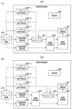
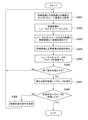
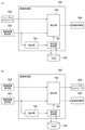
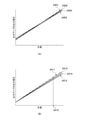
画像処理装置を含むシステム構成の一例を示す図である。It is a figure which shows an example of the system configuration including an image processing apparatus. 画像処理装置の学習処理の機能を示すブロック図である。It is a block diagram which shows the function of the learning processing of an image processing apparatus. 実施形態の学習処理の流れの一例を示すフローチャートである。It is a flowchart which shows an example of the flow of the learning process of an embodiment. ニューラルネットワークの一例を示す図である。It is a figure which shows an example of a neural network. 画像処理装置の推論処理の機能を示すブロック図である。It is a block diagram which shows the function of the inference processing of an image processing apparatus. 推論処理の流れの一例を示すフローチャートである。It is a flowchart which shows an example of the flow of inference processing. 画像処理部の機能を示すブロック図である。It is a block diagram which shows the function of an image processing part. アナログゲインの第1の例を示す図である。It is a figure which shows the 1st example of an analog gain. アナログゲインの第2の例を示す図である。It is a figure which shows the 2nd example of an analog gain. 第1の実施形態の学習処理の流れの一例を示すフローチャートである。It is a flowchart which shows an example of the flow of the learning process of 1st Embodiment. 第1の実施形態の学習処理の流れの他の例を示すフローチャートである。It is a flowchart which shows the other example of the flow of the learning process of 1st Embodiment. 第1の実施形態の推論処理の流れの一例を示すフローチャートである。It is a flowchart which shows an example of the flow of the inference processing of 1st Embodiment. F値と光量との関係、および、F値と補正値との関係の一例を示す図である。It is a figure which shows an example of the relationship between the F value and the amount of light, and the relationship between an F value and a correction value. 第2の実施形態の学習処理の流れの一例を示すフローチャートである。It is a flowchart which shows an example of the flow of the learning process of 2nd Embodiment. F値と補正値との関係の他の一例を示す図である。It is a figure which shows another example of the relationship between an F value and a correction value. 第2の実施形態の推論処理の流れの一例を示すフローチャートである。It is a flowchart which shows an example of the flow of the inference processing of 2nd Embodiment. 第3の実施形態の学習処理の流れの一例を示すフローチャートである。It is a flowchart which shows an example of the flow of the learning process of 3rd Embodiment. 第3の実施形態の推論処理の流れの一例を示すフローチャートである。It is a flowchart which shows an example of the flow of the inference processing of 3rd Embodiment. 周辺光量落ちの様子を示す図である。It is a figure which shows the state of the peripheral light falloff. 第4の実施形態の学習処理の流れの一例を示すフローチャートである。It is a flowchart which shows an example of the flow of the learning process of 4th Embodiment. 周辺光量落ち補正データのテーブルデータの例を示す図である。It is a figure which shows the example of the table data of the peripheral light falloff correction data. 第4の実施形態の推論処理の流れの一例を示すフローチャートである。It is a flowchart which shows an example of the flow of the inference processing of 4th Embodiment. センサ構造を示す図である。It is a figure which shows the sensor structure. フォトダイオードに入射する光量に対する各チャンネルの出力電圧を示す図である。It is a figure which shows the output voltage of each channel with respect to the amount of light incident on a photodiode. 第5の実施形態の学習処理の流れの一例を示すフローチャートである。It is a flowchart which shows an example of the flow of the learning process of 5th Embodiment. 第5の実施形態の推論処理の流れの一例を示すフローチャートである。It is a flowchart which shows an example of the flow of the inference processing of 5th Embodiment. 画像処理装置の学習処理の機能を示すブロック図である。It is a block diagram which shows the function of the learning processing of an image processing apparatus. 第6の実施形態の学習処理の流れの一例を示すフローチャートである。It is a flowchart which shows an example of the flow of the learning process of 6th Embodiment. 画像処理装置の推論処理の機能を示すブロック図である。It is a block diagram which shows the function of the inference processing of an image processing apparatus. 第6の実施形態の推論処理の流れの一例を示すフローチャートである。It is a flowchart which shows an example of the flow of the inference processing of 6th Embodiment.

以下、本発明の各実施形態について図面を参照しながら詳細に説明する。しかしながら、以下の各実施形態に記載されている構成はあくまで例示に過ぎず、本発明の範囲は各実施形態に記載されている構成によって限定されることはない。 Hereinafter, each embodiment of the present invention will be described in detail with reference to the drawings. However, the configurations described in the following embodiments are merely examples, and the scope of the present invention is not limited by the configurations described in the respective embodiments.

以下、各実施形態に共通する構成について説明する。図1は、画像処理装置を含むシステム構成の一例を示す図である。図1のシステム構成において、画像処理装置100は、撮像装置120、表示装置130およびストレージ装置140と接続される。システム構成は、図1の例には限定されない。例えば、画像処理装置100は、表示装置130とストレージ装置140とのうち何れかまたは両方を含んで構成されてもよい。また、画像処理装置100は、撮像装置120に組み込まれていてもよい。画像処理装置100は、エッジコンピュータや、ローカルサーバ、クラウドサーバ等であってもよい。 Hereinafter, the configuration common to each embodiment will be described. FIG. 1 is a diagram showing an example of a system configuration including an image processing device. In the system configuration of FIG. 1, the image processing device 100 is connected to the image pickup device 120, the display device 130, and the storage device 140. The system configuration is not limited to the example of FIG. For example, the image processing device 100 may be configured to include one or both of the display device 130 and the storage device 140. Further, the image processing device 100 may be incorporated in the image pickup device 120. The image processing device 100 may be an edge computer, a local server, a cloud server, or the like.

画像処理装置100は、各種の画像処理を行うとともに、学習処理および推論処理を行う。以下、学習処理は、ディープラーニングによる処理であるものとして説明する。ただし、画像処理装置100は、ディープラーニング以外の機械学習手法を用いて、機械学習を行ってもよい。例えば、画像処理装置100は、サポートベクターマシンや決定木、ロジスティクス回帰等の任意の機械学習手法を用いて、学習処理を行ってもよい。 The image processing apparatus 100 performs various image processing, as well as learning processing and inference processing. Hereinafter, the learning process will be described as being a process by deep learning. However, the image processing apparatus 100 may perform machine learning by using a machine learning method other than deep learning. For example, the image processing apparatus 100 may perform learning processing by using an arbitrary machine learning method such as a support vector machine, a decision tree, or logistics regression.

学習処理では、訓練画像と教師画像とがペアになった学習セットがニューラルネットワークに入力され、ニューラルネットワークの重みやバイアス等のネットワークパラメータ(以下、パラメータ)が調整される。多くの学習セットがニューラルネットワークに入力されて機械学習がされることで、ニューラルネットワークが出力する画像の特徴分布が教師画像の特徴分布に近づくように、パラメータが最適化される。学習済みのパラメータが設定されたニューラルネットワークに対して未知の画像が入力されると、ニューラルネットワークから推論結果(推論画像)が出力される。 In the learning process, a learning set in which a training image and a teacher image are paired is input to the neural network, and network parameters (hereinafter, parameters) such as weights and biases of the neural network are adjusted. By inputting many learning sets into the neural network and performing machine learning, the parameters are optimized so that the feature distribution of the image output by the neural network approaches the feature distribution of the teacher image. When an unknown image is input to the neural network in which the trained parameters are set, the inference result (inference image) is output from the neural network.

撮像装置120について説明する。撮像装置120は、レンズユニット121、撮像素子122およびカメラ制御回路123を有する。撮像装置120は、他の要素を含んでもよい。レンズユニット121は、絞りや光学レンズ、モータ等を含んで構成される。モータは、絞りや光学レンズを駆動させる。レンズユニット121は、複数枚の光学レンズを含んで構成されてもよい。レンズユニット121は、カメラ制御回路123が出力した制御信号に基づいて動作し、光学的に映像の拡大・縮小、焦点距離の調整等を行うことができる。レンズユニット121の絞りは、開口面積を制御することができる。これにより、絞り値(F値)が制御され、入射光量の調整を行うことができる。 The image pickup apparatus 120 will be described. The image pickup device 120 includes a lens unit 121, an image pickup element 122, and a camera control circuit 123. The image pickup apparatus 120 may include other elements. The lens unit 121 includes a diaphragm, an optical lens, a motor, and the like. The motor drives the aperture and the optical lens. The lens unit 121 may be configured to include a plurality of optical lenses. The lens unit 121 operates based on the control signal output by the camera control circuit 123, and can optically enlarge / reduce the image, adjust the focal length, and the like. The aperture of the lens unit 121 can control the aperture area. As a result, the aperture value (F value) is controlled, and the amount of incident light can be adjusted.

レンズユニット121を透過した光は、撮像素子122に結像される。撮像素子122は、CCDセンサやCMOSセンサ等のように、入射した光を電気信号に変換する。撮像素子122は、カメラ制御回路123からの制御信号に基づいて駆動される。撮像素子122は、各画素内の電荷のリセットや、読み出しのタイミング制御、読み出された信号に対して施すゲイン処理、アナログ信号からデジタル信号への変換等を行う機能を有する。撮像装置120は、撮像素子122が出力したデジタルの画像信号を、画像処理装置100の画像信号受信回路101に送信する。図1の例では、撮像装置120と画像処理装置100とは、無線または有線で通信可能に接続されており、画像処理装置100は、撮像装置120が送信した画像信号を受信する。カメラ制御回路123は、画像処理装置100のカメラ通信接続回路102から受信した駆動制御信号に基づいて、レンズユニット121および撮像素子122の駆動制御を行う。 The light transmitted through the lens unit 121 is imaged on the image pickup device 122. The image pickup device 122 converts the incident light into an electric signal like a CCD sensor, a CMOS sensor, or the like. The image sensor 122 is driven based on a control signal from the camera control circuit 123. The image pickup device 122 has functions such as resetting the charge in each pixel, controlling the timing of reading, gain processing applied to the read signal, converting an analog signal to a digital signal, and the like. The image pickup device 120 transmits the digital image signal output by the image pickup device 122 to the image signal receiving circuit 101 of the image processing device 100. In the example of FIG. 1, the image pickup device 120 and the image processing device 100 are connected wirelessly or by wire so as to be communicable, and the image processing device 100 receives the image signal transmitted by the image pickup device 120. The camera control circuit 123 performs drive control of the lens unit 121 and the image pickup element 122 based on the drive control signal received from the camera communication connection circuit 102 of the image processing device 100.

次に、画像処理装置100について説明する。画像信号受信回路101は、撮像装置120から画像信号を受信する。カメラ通信接続回路102は、レンズユニット121および撮像素子122を駆動する駆動制御信号を撮像装置120に送信する。画像処理回路103は、画像信号受信回路101が受信した画像信号に対して、画像処理を施す。この画像処理は、CPU105により行われてもよい。また、画像処理回路103は、ニューラルネットワークを用いたノイズ低減処理を行う機能を有している。画像処理回路103は、画像処理を行うマイクロプロセッサ、DSP、FPGA、ASICなどの回路により実現されてもよいし、CPU105により実現されてもよい。 Next, the image processing apparatus 100 will be described. The image signal receiving circuit 101 receives an image signal from the image pickup apparatus 120. The camera communication connection circuit 102 transmits a drive control signal for driving the lens unit 121 and the image pickup device 122 to the image pickup device 120. The image processing circuit 103 performs image processing on the image signal received by the image signal receiving circuit 101. This image processing may be performed by the CPU 105. Further, the image processing circuit 103 has a function of performing noise reduction processing using a neural network. The image processing circuit 103 may be realized by a circuit such as a microprocessor, DSP, FPGA, or ASIC that performs image processing, or may be realized by a CPU 105.

フレームメモリ104は、画像信号を一時的に記憶するメモリである。フレームメモリ104は、画像信号を一時的に記憶し、記憶した画像信号を高速に読み出すことが可能な素子である。画像信号のデータ量が多くなると、高速且つ大容量のメモリが、フレームメモリ104に適用されることが好ましい。例えば、フレームメモリ104としては、DDR3-SDRAM(Dual Data Rate 3 - Synchronous Dynamic RAM)等を適用することができる。DDR3-SDRAMがフレームメモリ104に適用された場合、様々な処理が可能になる。例えば、DDR3-SDRAMは、時間的に異なる画像の合成や必要な領域の切り出し等の画像処理を行う際に好適な素子である。ただし、フレームメモリ104は、DDR3-SDRAMには限定されない。 The frame memory 104 is a memory for temporarily storing an image signal. The frame memory 104 is an element capable of temporarily storing an image signal and reading the stored image signal at high speed. When the amount of data of the image signal becomes large, it is preferable that a high-speed and large-capacity memory is applied to the frame memory 104. For example, as the frame memory 104, DDR3-SDRAM (Double Data Rate 3-Synchronous Dynamic RAM) or the like can be applied. When DDR3- SDRAM is applied to the frame memory 104, various processing becomes possible. For example, DDR3- SDRAM is a suitable element for performing image processing such as synthesizing images different in time and cutting out a necessary region. However, the frame memory 104 is not limited to DDR3- SDRAM.

CPU105は、ROM106に記憶されている制御プログラムや各種パラメータを読み出して、RAM107に展開する。CPU105がRAM107に展開されたプログラムを実行することで、各実施形態の処理が実現される。メタデータ抽出回路108は、レンズ駆動条件やセンサ駆動条件等のメタデータを抽出する。GPU109は、グラフィックス・プロセッシング・ユニットであり、高速に演算処理が可能なプロセッサである。GPU109は、表示装置130に表示させる画面を生成するために用いられるが、ディープラーニングの演算処理にも好適に使用される。GPU109により生成された画像は、表示駆動回路110および表示装置接続回路111を介して、表示装置130に出力される。これにより、表示装置130に画像が表示される。 The CPU 105 reads out the control program and various parameters stored in the ROM 106 and expands them in the RAM 107. The processing of each embodiment is realized by the CPU 105 executing the program expanded in the RAM 107. The metadata extraction circuit 108 extracts metadata such as lens drive conditions and sensor drive conditions. The GPU 109 is a graphics processing unit, which is a processor capable of high-speed arithmetic processing. The GPU 109 is used to generate a screen to be displayed on the display device 130, but is also suitably used for deep learning arithmetic processing. The image generated by the GPU 109 is output to the display device 130 via the display drive circuit 110 and the display device connection circuit 111. As a result, the image is displayed on the display device 130.

ストレージ駆動回路112は、ストレージ接続回路113を介して、ストレージ装置140を駆動させる。ストレージ装置140は、多くの画像データを記憶する。ストレージ装置140が記憶する画像データとしては、訓練画像(学習用画像)および訓練画像に対応する教師画像(正解画像)がある。訓練画像と教師画像とは1つのペア(学習セット)を構成する。ストレージ装置140には、複数の学習セットが記憶される。ストレージ装置140は、学習処理により生成された学習済みのパラメータを記憶してもよい。以下、CPU105の制御により学習処理が行われる際には、ストレージ装置140に予め記憶された画像データが用いられ、推論処理が行われる際には、撮像装置120から取得した画像信号が使用されるものとして説明する。ただし、上記の例には限定されない。例えば、推論処理が行われる際に、ストレージ装置140や外部の記憶装置等に記憶された画像信号が使用されてもよい。 The storage drive circuit 112 drives the storage device 140 via the storage connection circuit 113. The storage device 140 stores a large amount of image data. The image data stored in the storage device 140 includes a training image (learning image) and a teacher image (correct image) corresponding to the training image. The training image and the teacher image form one pair (learning set). A plurality of learning sets are stored in the storage device 140. The storage device 140 may store the learned parameters generated by the learning process. Hereinafter, when the learning process is performed under the control of the CPU 105, the image data stored in advance in the storage device 140 is used, and when the inference process is performed, the image signal acquired from the image pickup device 120 is used. Explain as a thing. However, the present invention is not limited to the above example. For example, when the inference process is performed, the image signal stored in the storage device 140, an external storage device, or the like may be used.

学習処理で使用される訓練画像は、ベイヤー配列の画像や、三板式の撮像センサで撮影された画像、垂直色分離方式の撮像センサ等で撮影された画像であってもよい。また、訓練画像は、ベイヤー配列以外の配列(ハニカム構造や周期性の低いカラーフィルタ配列等)の画像であってもよい。また、訓練画像がベイヤー配列の画像である場合、ベイヤー配列の1chの画像であってもよいし、カラーチャネルごとに分離された画像であってもよい。教師画像も同様である。訓練画像および教師画像は、上述した例には限定されない。 The training image used in the learning process may be an image of the Bayer arrangement, an image taken by a three-plate type image pickup sensor, an image taken by a vertical color separation type image pickup sensor, or the like. Further, the training image may be an image of an arrangement other than the Bayer arrangement (honeycomb structure, color filter arrangement having low periodicity, etc.). When the training image is an image of the Bayer arrangement, it may be an image of 1ch of the Bayer arrangement or an image separated for each color channel. The same applies to the teacher image. Training images and teacher images are not limited to the examples described above.

次に、学習処理について説明する。図2(A)および(B)は、画像処理装置100の学習処理の機能を示すブロック図である。まず、図2(A)について説明する。訓練画像保持部202は、ストレージ装置201から取得された訓練画像を保持する。教師画像保持部203は、ストレージ装置201から取得された教師画像を保持する。訓練画像保持部202および教師画像保持部203は、例えば、RAM107等により実現されてもよい。 Next, the learning process will be described. 2A and 2B are block diagrams showing a function of learning processing of the image processing apparatus 100. First, FIG. 2A will be described. The training image holding unit 202 holds the training image acquired from the storage device 201. The teacher image holding unit 203 holds the teacher image acquired from the storage device 201. The training image holding unit 202 and the teacher image holding unit 203 may be realized by, for example, a RAM 107 or the like.

教師画像と訓練画像とは同一の被写体が写っている画像である。訓練画像はノイズを含む画像であり、教師画像はノイズを含まない正解画像である。ただし、教師画像は若干のノイズを含んでいてもよい。例えば、CPU105や画像処理回路103が、教師画像に対してノイズを付加することで、訓練画像が生成されてもよい。また、訓練画像は、正解画像と同一の被写体をノイズが発生し得る状況で撮影された画像(例えば、高感度の設定で撮影された画像)であってもよい。訓練画像は低照度で撮影された画像に対して教師画像と同程度に感度補正が施された画像であってもよい。また、教師画像は低感度(訓練画像よりも低い感度)で撮影された画像であってもよい。 The teacher image and the training image are images showing the same subject. The training image is an image containing noise, and the teacher image is a correct image containing no noise. However, the teacher image may contain some noise. For example, the training image may be generated by the CPU 105 or the image processing circuit 103 adding noise to the teacher image. Further, the training image may be an image taken in a situation where noise may occur in the same subject as the correct image (for example, an image taken with a high sensitivity setting). The training image may be an image in which the sensitivity of the image taken in low illuminance is corrected to the same degree as that of the teacher image. Further, the teacher image may be an image taken with low sensitivity (sensitivity lower than the training image).

ニューラルネットワーク204は、多層構造のニューラルネットワークである。詳細は後述する。ニューラルネットワーク204に対する学習(ディープラーニング)が行われる際には、推論精度の向上を図るために、多様なノイズパターンや被写体が含まれる訓練画像が用いられることが好ましい。多様なノイズパターンや被写体が含まれる訓練画像を用いて、ニューラルネットワーク204の学習が行われることで、訓練画像に含まれていないノイズパターンや被写体を含む未知の画像を入力としたときの推論処理の精度が向上する。ニューラルネットワーク204のディープラーニングに用いられる訓練画像の枚数が不足している場合、例えば、切り取りや回転、反転等の水増し処理が訓練画像に施されてもよい。この場合、教師画像に対しても同一の水増し処理が行われる。また、訓練画像と教師画像とはそれぞれ、信号の上限値(飽和輝度値)で除算され、正規化されることが好ましい。ニューラルネットワーク204は、訓練画像を入力すると、出力画像を生成し、出力する。 The neural network 204 is a multi-layered neural network. Details will be described later. When learning (deep learning) for the neural network 204 is performed, it is preferable to use a training image including various noise patterns and subjects in order to improve the inference accuracy. By learning the neural network 204 using a training image containing various noise patterns and subjects, inference processing when an unknown image including noise patterns and subjects not included in the training image is input. The accuracy of is improved. When the number of training images used for deep learning of the neural network 204 is insufficient, for example, padding processing such as cutting, rotation, and inversion may be applied to the training images. In this case, the same padding process is performed on the teacher image. Further, it is preferable that the training image and the teacher image are each divided by the upper limit value (saturation luminance value) of the signal and normalized. When the training image is input, the neural network 204 generates and outputs an output image.

画像処理部205は、ニューラルネットワーク204の出力画像と教師画像とに対して、画像処理を行う。画像処理の例としては、ISO感度補正、F値補正、色抑圧処理、色曲がり補正、カラーバランス補正、周辺光量落ち補正、チャネル間ゲイン補正、フリッカ補正、および、圧縮および伸張処理などがある。ニューラルネットワーク204の学習処理が完了すると、学習済みのパラメータが生成される。これにより、学習済みのパラメータをニューラルネットワーク204に適用した推論処理を行うことができる。画像処理部205は、学習処理で行う補正の条件と推論処理で行う補正の条件とを合わせることが好ましい。これにより、推論処理が行われる際の推論精度が向上する。図2(A)では、画像処理部205はニューラルネットワーク204の出力側にあるが、図2(B)に示されるように、画像処理部205はニューラルネットワーク204の入力側にあってもよい。画像処理部205は、例えば、画像処理回路103やCPU105等により実現される。 The image processing unit 205 performs image processing on the output image and the teacher image of the neural network 204. Examples of image processing include ISO sensitivity correction, F value correction, color suppression processing, color bending correction, color balance correction, peripheral light falloff correction, interchannel gain correction, flicker correction, and compression and decompression processing. When the training process of the neural network 204 is completed, the trained parameters are generated. As a result, inference processing can be performed by applying the learned parameters to the neural network 204. It is preferable that the image processing unit 205 matches the condition of the correction performed in the learning process and the condition of the correction performed in the inference process. This improves the inference accuracy when the inference process is performed. In FIG. 2A, the image processing unit 205 is on the output side of the neural network 204, but as shown in FIG. 2B, the image processing unit 205 may be on the input side of the neural network 204. The image processing unit 205 is realized by, for example, an image processing circuit 103, a CPU 105, or the like.

誤差評価部206は、画像処理部205が補正した出力画像と教師画像との誤差を算出する。教師画像と訓練画像とは、同じ並びの色成分の配列となっている。誤差評価部206は、例えば、各画素についての平均二乗誤差や、各画素の差分の絶対値の総和を用いて、誤差(損失誤差)を算出してもよい。また、誤差評価部206は、決定係数等の他の指標を用いて、誤差を算出することにより、誤差の評価を行ってもよい。パラメータ調整部207は、誤差評価部206が算出した誤差が小さくなるようにニューラルネットワーク204の各パラメータを更新する。誤差評価部206およびパラメータ調整部207は、例えば、CPU105により実現されてもよいし、GPU109により実現されてもよいし、CPU105とGPU109との協働動作により実現されてもよい。誤差評価部206およびパラメータ調整部207は、学習手段に対応する。 The error evaluation unit 206 calculates the error between the output image corrected by the image processing unit 205 and the teacher image. The teacher image and the training image have the same arrangement of color components. The error evaluation unit 206 may calculate an error (loss error) by using, for example, the mean square error for each pixel or the sum of the absolute values of the differences of each pixel. Further, the error evaluation unit 206 may evaluate the error by calculating the error using another index such as the coefficient of determination. The parameter adjustment unit 207 updates each parameter of the neural network 204 so that the error calculated by the error evaluation unit 206 becomes small. The error evaluation unit 206 and the parameter adjustment unit 207 may be realized by, for example, the CPU 105, the GPU 109, or the cooperative operation of the CPU 105 and the GPU 109. The error evaluation unit 206 and the parameter adjustment unit 207 correspond to the learning means.

パラメータ調整部207は、例えば、誤差逆伝搬法を用いて、ニューラルネットワーク204の各パラメータを更新してもよい。パラメータ調整部207は、他の手法を用いて、ニューラルネットワーク204の各パラメータを更新してもよい。このとき、パラメータ調整部207は、ニューラルネットワーク204の各パラメータの更新量を固定してもよいし、変動させてもよい。以上のように、画像処理部205により画像処理がされた出力画像と教師画像との誤差が小さくなるようにニューラルネットワーク204の各パラメータが更新される。これにより、ニューラルネットワーク204に未知の画像が入力されたときの推論精度が向上する。 The parameter adjustment unit 207 may update each parameter of the neural network 204 by using, for example, an error back propagation method. The parameter adjusting unit 207 may update each parameter of the neural network 204 by using another method. At this time, the parameter adjusting unit 207 may fix or change the update amount of each parameter of the neural network 204. As described above, each parameter of the neural network 204 is updated so that the error between the output image processed by the image processing unit 205 and the teacher image becomes small. This improves the inference accuracy when an unknown image is input to the neural network 204.

パラメータ保存領域208-1~208-n(nは2以上の整数)は、更新されたパラメータを保存する領域である。パラメータ保存領域208-1~208-n(以下、パラメータ保存領域208と総称する)は、画像処理の補正条件に応じて学習処理がされたニューラルネットワーク204のパラメータを保存するための領域である。つまり、各パラメータ保存領域208には、それぞれ異なる画像処理の補正条件で学習処理がされた学習済みのパラメータが、それぞれの画像処理の補正条件に対応付けて保存される。パラメータ保存領域208は、RAM107の一部の記憶領域であってもよいし、ストレージ装置201の一部の記憶領域であってもよい。制御部209は、学習処理に関する各種の制御を行う。制御部209は、CPU105により実現される。 The parameter storage areas 208-1 to 208-n (n is an integer of 2 or more) are areas for storing updated parameters. The parameter storage areas 208-1 to 208-n (hereinafter collectively referred to as parameter storage areas 208) are areas for storing the parameters of the neural network 204 that has been trained according to the correction conditions of the image processing. That is, in each parameter storage area 208, the trained parameters that have been trained under the correction conditions of different image processing are stored in association with the correction conditions of the respective image processing. The parameter storage area 208 may be a part of the storage area of the RAM 107 or a part of the storage area of the storage device 201. The control unit 209 performs various controls related to the learning process. The control unit 209 is realized by the CPU 105.

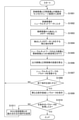
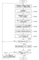
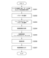
次に、学習処理の流れについて説明する。図3は、学習処理の流れの一例を示すフローチャートである。図3では、ステップをSと記載しており、これは他のフローチャートの図でも同様である。S301で、制御部209は、訓練画像および教師画像のペア(学習セット)をストレージ装置301から取得する。S302で、制御部209は、取得した複数の学習セットのうち1つの学習セットの訓練画像をニューラルネットワーク204に入力する。ニューラルネットワーク204が行う処理により、出力画像が生成される。訓練画像のノイズ量やノイズパターンは、他の訓練画像のノイズ量やノイズパターンと異なっている場合もあり、同じ場合もある。 Next, the flow of the learning process will be described. FIG. 3 is a flowchart showing an example of the flow of the learning process. In FIG. 3, the step is described as S, which is the same in the other flowcharts. In S301, the control unit 209 acquires a pair (learning set) of the training image and the teacher image from the storage device 301. In S302, the control unit 209 inputs the training image of one of the acquired learning sets to the neural network 204. The output image is generated by the process performed by the neural network 204. The noise amount and noise pattern of the training image may be different from the noise amount and noise pattern of other training images, and may be the same.

S303で、画像処理部205は、ニューラルネットワーク304からの出力画像と教師画像とに対して、画像処理を施す。上述したように、画像処理部205は、ニューラルネットワーク204の入力側にあってもよいし、出力側にあってもよい。つまり、S303の処理は、S302の処理より前に行われてもよい。 In S303, the image processing unit 205 performs image processing on the output image from the neural network 304 and the teacher image. As described above, the image processing unit 205 may be on the input side or the output side of the neural network 204. That is, the processing of S303 may be performed before the processing of S302.

S304で、誤差評価部206は、画像処理が施された出力画像と教師画像との誤差を算出する。S305で、パラメータ調整部207は、算出した誤差が小さくなるように、誤差逆伝播法を用いて、ニューラルネットワーク204の各パラメータを更新する。S306で、制御部209は、所定の終了条件を満たしたかを判定する。制御部209は、学習回数が規定回数に達した場合に、所定の終了条件を満たしたと判定してもよい。また、制御部209は、算出された誤差が所定値以下となった場合に、所定の終了条件を満たしたと判定してもよい。また、制御部209は、上記の誤差の減少度合いが所定度合い以下となった場合やユーザによる終了指示があった場合に、所定の終了条件を満たしたと判定してもよい。制御部209は、S306でNOと判定した場合、フローをS301に戻す。この場合、新たな訓練画像と正解画像との学習セットを用いて、S301~S305の処理が行われる。一方、制御部209は、S306でYESと判定した場合、フローをS307に進める。 In S304, the error evaluation unit 206 calculates the error between the output image subjected to the image processing and the teacher image. In S305, the parameter adjustment unit 207 updates each parameter of the neural network 204 by using the error back propagation method so that the calculated error becomes small. In S306, the control unit 209 determines whether or not the predetermined end condition is satisfied. When the number of learnings reaches a predetermined number of times, the control unit 209 may determine that the predetermined end condition is satisfied. Further, the control unit 209 may determine that the predetermined end condition is satisfied when the calculated error is equal to or less than the predetermined value. Further, the control unit 209 may determine that the predetermined end condition is satisfied when the degree of reduction of the above error is less than or equal to the predetermined degree or when the user gives an end instruction. When the control unit 209 determines NO in S306, the control unit 209 returns the flow to S301. In this case, the processes of S301 to S305 are performed using the learning set of the new training image and the correct answer image. On the other hand, if the control unit 209 determines YES in S306, the control unit 209 advances the flow to S307.

S307で、制御部209は、更新されたパラメータ(学習済みのパラメータ)を、画像処理の条件ごとに異なるパラメータ保存領域208に保存する。このとき、制御部209は、学習処理により更新されたパラメータだけでなく、パラメータに関連付けてニューラルネットワーク204のモデル構造等に関する情報をパラメータ保存領域208に保存してもよい。S308で、制御部209は、全ての画像処理の補正条件についてのパラメータを取得したかを判定する。制御部209は、S308でYESと判定した場合、図3のフローチャートの処理を終了させる。一方、制御部209は、S308でNOと判定した場合、フローをS309に進める。S309で、制御部209は、画像処理の補正条件を変更する。そして、制御部209は、フローをS301に戻す。これにより、画像処理の条件を変更した学習処理が新たに行われる。 In S307, the control unit 209 stores the updated parameters (learned parameters) in the parameter storage area 208 that differs depending on the image processing conditions. At this time, the control unit 209 may store not only the parameters updated by the learning process but also information related to the model structure of the neural network 204 in association with the parameters in the parameter storage area 208. In S308, the control unit 209 determines whether or not the parameters for the correction conditions of all the image processing have been acquired. If the control unit 209 determines YES in S308, the control unit 209 ends the processing of the flowchart of FIG. On the other hand, if the control unit 209 determines NO in S308, the control unit 209 advances the flow to S309. In S309, the control unit 209 changes the correction conditions for image processing. Then, the control unit 209 returns the flow to S301. As a result, the learning process in which the image processing conditions are changed is newly performed.

次に、ニューラルネットワーク204について説明する。図4は、ニューラルネットワーク204の一例を示す図である。各実施形態のニューラルネットワーク204は、畳み込みニューラルネットワーク(CNN)であるものとして説明する。ただし、ニューラルネットワーク204は、CNNには限定されない。例えば、ニューラルネットワーク204は、GAN(Generative Adversarial Network)やスキップコネクション、RNN(Recurrent Neural Network)等であってもよい。また、ニューラルネットワーク204の代わりに、他の機械学習手法により機械学習された学習モデルが用いられてもよい。学習モデルとしては、例えば、上述したサポートベクターマシンや決定木等を適用できる。 Next, the neural network 204 will be described. FIG. 4 is a diagram showing an example of the neural network 204. The neural network 204 of each embodiment is described as being a convolutional neural network (CNN). However, the neural network 204 is not limited to CNN. For example, the neural network 204 may be a GAN (Generative Adversarial Network), a skip connection, an RNN (Recurrent Neural Network), or the like. Further, instead of the neural network 204, a learning model machine-learned by another machine learning method may be used. As the learning model, for example, the above-mentioned support vector machine, decision tree, or the like can be applied.

ニューラルネットワーク204に対して、入力画像401が入力されると、畳み込み演算402が実施される。入力画像401は、画像データであってもよいし、画像データの特徴マップを表すデータであってもよい。畳み込み行列403は、入力画像401に対して畳み込み演算を行うフィルタである。入力画像401と畳み込み行列403との畳み込み演算によって出力された結果に、バイアス404が加算される。特徴マップ405は、バイアス404を加算した畳み込み演算の演算結果である。ニューラルネットワーク204の中間層の層数やニューロン数、結合係数、重み等は、任意の値であってよい。また、FPGA等のプログラミング回路にニューラルネットワーク204が実装される場合、ニューロン間の結合や重みは削減されてもよい。この点は、GPU109が、ニューラルネットワーク204の処理を行う場合も同様である。また、学習処理および推論処理は、複数のカラーチャネルを纏めて実行されてもよいし、複数の色のそれぞれについて個別に実行されてもよい。 When the input image 401 is input to the neural network 204, the convolution operation 402 is performed. The input image 401 may be image data or data representing a feature map of the image data. The convolution matrix 403 is a filter that performs a convolution operation on the input image 401. Bias 404 is added to the result output by the convolution operation of the input image 401 and the convolution matrix 403. The feature map 405 is the calculation result of the convolution operation in which the bias 404 is added. The number of layers, the number of neurons, the coupling coefficient, the weight, and the like of the intermediate layer of the neural network 204 may be arbitrary values. Further, when the neural network 204 is implemented in a programming circuit such as FPGA, the connection and weight between neurons may be reduced. This point is the same when the GPU 109 processes the neural network 204. Further, the learning process and the inference process may be executed collectively for a plurality of color channels, or may be executed individually for each of the plurality of colors.

CNNでは、入力画像に対してフィルタによる畳み込み演算が実行されることで、入力画像の特徴マップが抽出される。フィルタのサイズは、任意のサイズであってよい。後段の層において、前段の層で抽出された特徴マップに別のフィルタによる畳み込み演算が実行されることで、順次異なる特徴マップが抽出される。中間層の各層では、入力信号に対して接続の強度を表すフィルタの重みが乗算されて、さらにバイアスが加算される。この演算結果に対して活性化関数が適用されることで、各ニューロンにおける出力信号が得られる。各層における重みおよびバイアスがパラメータ(ネットワークパラメータ)であり、パラメータの値が学習処理により更新される。機械学習により更新されたパラメータが、学習済みのパラメータである。活性化関数としては、シグモイド関数やReLU関数等の任意の関数を適用することができる。各実施形態で適用される活性化関数は、以下の式1で表されるLeaky ReLU関数であるものとして説明する。ただし、活性化関数としては、シグモイド関数やtanh関数等、任意の活性化関数が適用されてもよい。 In CNN, the feature map of the input image is extracted by executing the convolution operation by the filter on the input image. The size of the filter may be any size. In the latter layer, a convolution operation by another filter is executed on the feature map extracted in the previous layer, so that different feature maps are sequentially extracted. In each layer of the intermediate layer, the input signal is multiplied by the weight of the filter representing the strength of the connection, and the bias is further added. By applying the activation function to this calculation result, the output signal in each neuron can be obtained. The weights and biases in each layer are parameters (network parameters), and the values of the parameters are updated by the learning process. The parameters updated by machine learning are the learned parameters. As the activation function, any function such as a sigmoid function or a ReLU function can be applied. The activation function applied in each embodiment will be described as being a Leaky ReLU function represented by the following equation 1. However, as the activation function, any activation function such as a sigmoid function or a tanh function may be applied.

Figure 2022008037000002
以上の式(1)において、maxは、引数のうち最大値を出力する関数を表す。
Figure 2022008037000002
In the above equation (1), max represents a function that outputs the maximum value among the arguments.

上述したように、パラメータ保存領域208-1~208-nには、画像処理の補正条件ごとに、学習処理により更新されたパラメータ(学習済みのパラメータ)を保存される。推論処理が行われる際には、画像処理の補正条件の応じたパラメータがパラメータ保存領域208-1~208-nのうち何れかから取得される。そして、取得されたパラメータがニューラルネットワーク204に適用されて、推論処理が行われる。これにより、補正条件が異なる画像処理を行う場合の推論精度を向上させることができる。 As described above, the parameters updated by the learning process (learned parameters) are stored in the parameter storage areas 208-1 to 208-n for each correction condition of the image processing. When the inference processing is performed, the parameters corresponding to the correction conditions of the image processing are acquired from any of the parameter storage areas 208-1 to 208-n. Then, the acquired parameters are applied to the neural network 204, and inference processing is performed. This makes it possible to improve the inference accuracy when performing image processing with different correction conditions.

上述した例では、ニューラルネットワーク204の学習処理は、ノイズを含む訓練画像と、ノイズを含まない、あるいは、ノイズが小さい教師画像とを用いて行われる。これにより、機械学習がされたニューラルネットワーク204に未知のノイズを含む画像が入力されたときに、ニューラルネットワーク204による推論処理により、ノイズを低減した画像を推論することができる。上述した例は、ノイズ低減の処理についての学習処理であるが、ノイズ低減以外の処理についての学習処理にも適用可能である。例えば、ニューラルネットワークにより超解像の推論処理が行われる場合、教師画像をダウンサンプリングした訓練画像と教師画像とを用いて、学習処理を行うことができる。このとき、訓練画像と教師画像とはサイズ合わせが行われてもよい。 In the above example, the training process of the neural network 204 is performed using a training image containing noise and a teacher image containing no noise or having low noise. As a result, when an image containing unknown noise is input to the machine-learned neural network 204, the noise-reduced image can be inferred by the inference processing by the neural network 204. The above-mentioned example is a learning process for noise reduction processing, but it can also be applied to learning processing for processes other than noise reduction. For example, when super-resolution inference processing is performed by a neural network, learning processing can be performed using a training image obtained by downsampling a teacher image and a teacher image. At this time, the size of the training image and the teacher image may be adjusted.

次に、推論処理について説明する。図5は、画像処理装置100の推論処理の機能を示すブロック図である。取得部501は、撮像装置120から、撮像画像およびパラメータ選択の際に用いられる情報を取得する。パラメータ選択の際に用いられる情報は、パラメータ保存領域208-1~208-nに保存されている各パラメータのうち選択するパラメータを特定するために用いられる。パラメータ選択の際に用いられる情報は、メタデータであってもよい。メタデータは、撮像画像に付加された情報(レンズユニット121や撮像装置120等の設定条件の情報)であってもよいし、メタデータ抽出回路108から抽出された情報であってもよい。ここでは、パラメータ選択の際に用いられる情報は、画像処理に関する情報である。パラメータ選択の際に用いられる情報が上記のメタデータである場合、取得部501は、パラメータ選択の際に用いられる情報を別個に取得しなくてもよい。 Next, the inference process will be described. FIG. 5 is a block diagram showing a function of inference processing of the image processing apparatus 100. The acquisition unit 501 acquires the captured image and the information used for parameter selection from the image pickup device 120. The information used at the time of parameter selection is used to specify the parameter to be selected from each parameter stored in the parameter storage areas 208-1 to 208-n. The information used in parameter selection may be metadata. The metadata may be information added to the captured image (information on setting conditions of the lens unit 121, the image pickup device 120, or the like), or information extracted from the metadata extraction circuit 108. Here, the information used at the time of parameter selection is information related to image processing. When the information used for parameter selection is the above metadata, the acquisition unit 501 does not have to separately acquire the information used for parameter selection.

選択手段としてのパラメータ選択部502は、取得されたパラメータ選択の際に用いられる情報に対応するパラメータを、パラメータ保存領域208-1~208-nのうち何れかから取得する。パラメータ保存領域208―1~208-nに保存される各パラメータは、上述した学習処理により生成されるパラメータであるが、画像処理装置100以外の外部装置で学習処理されたパラメータであってもよい。この場合、外部装置は、ニューラルネットワーク204と同じネットワーク構造を有するニューラルネットワークで、上述した学習処理を行う。そして、画像処理装置100は、学習処理により生成されたパラメータを取得し、パラメータ保存領域208―1~208-nに保存してもよい。 The parameter selection unit 502 as the selection means acquires the parameter corresponding to the acquired information used at the time of parameter selection from any of the parameter storage areas 208-1 to 208-n. Each parameter stored in the parameter storage areas 208-1 to 208-n is a parameter generated by the above-mentioned learning process, but may be a parameter learned by an external device other than the image processing device 100. .. In this case, the external device is a neural network having the same network structure as the neural network 204, and performs the above-mentioned learning process. Then, the image processing apparatus 100 may acquire the parameters generated by the learning process and store them in the parameter storage areas 208-1 to 208-n.

パラメータ選択部502により選択された学習済みのパラメータは、ニューラルネットワーク204に適用される。そして、ニューラルネットワーク204には、撮像装置120から取得された撮像画像が入力される。推論手段としてのニューラルネットワーク204は、撮像画像が入力されると、推論処理を行い、推論結果として推論画像を生成する。推論画像出力部503は、ストレージ装置201に、生成された推論画像を出力する。制御部504は、推論処理に関する各種の制御を行う。取得部501、パラメータ選択部502、推論画像出力部503および制御部504は、例えば、CPU105により実現される。 The trained parameters selected by the parameter selection unit 502 are applied to the neural network 204. Then, the captured image acquired from the imaging device 120 is input to the neural network 204. When the captured image is input, the neural network 204 as an inference means performs an inference process and generates an inference image as an inference result. The inference image output unit 503 outputs the generated inference image to the storage device 201. The control unit 504 performs various controls related to the inference process. The acquisition unit 501, the parameter selection unit 502, the inference image output unit 503, and the control unit 504 are realized by, for example, the CPU 105.

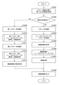
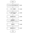
図6は、本実施形態の推論処理の流れの一例を示すフローチャートである。S601で、取得部501は、パラメータ選択の際に用いられる情報を取得する。S602で、パラメータ選択部502は、取得した情報に対応するパラメータを、パラメータ保存領域208-1~208-nから選択する。パラメータ保存領域208-1~208-nに保存されている各パラメータは、それぞれ異なる画像処理の補正条件で更新されたパラメータである。取得されたパラメータ選択の際に用いられる情報は、画像処理の補正条件に関する情報である。パラメータ選択部502は、取得したパラメータ選択の際に用いられる情報が表す画像処理の補正条件と同じであるか、または画像処理の補正条件が近いパラメータを取得する。 FIG. 6 is a flowchart showing an example of the flow of the inference process of the present embodiment. In S601, the acquisition unit 501 acquires the information used at the time of parameter selection. In S602, the parameter selection unit 502 selects the parameter corresponding to the acquired information from the parameter storage areas 208-1 to 208-n. Each parameter stored in the parameter storage areas 208-1 to 208-n is a parameter updated under the correction conditions of different image processing. The information used when selecting the acquired parameters is information regarding correction conditions for image processing. The parameter selection unit 502 acquires parameters that are the same as the image processing correction conditions represented by the information used at the time of the acquired parameter selection, or that the image processing correction conditions are close to each other.

S603で、制御部504は、選択されたパラメータをニューラルネットワーク204に適用する。これにより、ニューラルネットワーク204による推論処理を行うことが可能な状態になる。取得部501は、撮像装置120から、撮像画像を取得する。S604で取得される撮像画像は、RAW画像であるものとする。RAW画像に符号化処理が施されている場合、CPU105または画像処理回路103は、復号処理を行う。取得部501は、ストレージ装置140やROM106、RAM107等から、RAW画像を取得してもよい。 In S603, the control unit 504 applies the selected parameter to the neural network 204. As a result, it becomes possible to perform inference processing by the neural network 204. The acquisition unit 501 acquires an captured image from the image pickup device 120. The captured image acquired by S604 is assumed to be a RAW image. When the RAW image is coded, the CPU 105 or the image processing circuit 103 performs the decoding process. The acquisition unit 501 may acquire RAW images from the storage device 140, ROM 106, RAM 107, and the like.

S605で、制御部504は、取得した撮像画像をニューラルネットワーク204に入力する。このとき、制御部504は、取得した撮像画像をニューラルネットワーク204に入力するための入力画像に変換してもよい。推論処理を行う際にニューラルネットワーク204に入力する撮像画像のサイズと、学習処理を行った際にニューラルネットワーク204に入力した訓練画像のサイズとは同じであってもよいし、異なっていてもよい。制御部504は、撮像画像を入力画像に変換する際に、信号の規格化や色成分ごとの分離等を行ってもよい。 In S605, the control unit 504 inputs the acquired captured image to the neural network 204. At this time, the control unit 504 may convert the acquired captured image into an input image for inputting to the neural network 204. The size of the captured image input to the neural network 204 when performing the inference process may be the same as or different from the size of the training image input to the neural network 204 when performing the learning process. .. When the captured image is converted into the input image, the control unit 504 may normalize the signal, separate each color component, and the like.

S606で、ニューラルネットワーク204は、推論処理を行う。ニューラルネットワーク204による推論処理は、GPU109により実行されてもよいし、CPU105により実行されてもよいし、CPU105とGPU109との協働動作により実行されてもよい。S606の推論処理により、ニューラルネットワーク204の推論結果として推論画像が生成される。S607で、推論画像出力部503は、生成された推論画像をストレージ装置140に出力する。推論画像出力部503は、生成された推論画像を、ROM106やRAM107、表示装置130等に出力してもよい。S604で、撮像画像から入力画像に変換している場合、制御部504は、推論画像に対して、S604で行った変換を元に戻す逆変換を行ってもよい。 In S606, the neural network 204 performs inference processing. The inference process by the neural network 204 may be executed by the GPU 109, may be executed by the CPU 105, or may be executed by the cooperative operation of the CPU 105 and the GPU 109. The inference process of S606 generates an inference image as an inference result of the neural network 204. In S607, the inference image output unit 503 outputs the generated inference image to the storage device 140. The inference image output unit 503 may output the generated inference image to the ROM 106, the RAM 107, the display device 130, or the like. When the captured image is converted to the input image in S604, the control unit 504 may perform an inverse conversion of the inferred image to undo the conversion performed in S604.

他の撮像画像の推論処理が行われる場合、画像処理装置100は、S601~S607の各処理を実行する。上述したように、パラメータ保存領域208―1~208-nには、画像処理の補正条件ごとに学習処理されたニューラルネットワーク204のパラメータが保存される。そして、パラメータ選択部502は、画像処理の補正条件に基づいて、対応するパラメータを、パラメータ保存領域208―1~208-nから選択する。これにより、最適なパラメータを用いた、撮像画像の推論処理を行うことができる。その結果、ノイズを低減した画像を得ることができる。 When the inference processing of another captured image is performed, the image processing apparatus 100 executes each processing of S601 to S607. As described above, the parameters of the neural network 204 learned and processed for each correction condition of the image processing are stored in the parameter storage areas 208-1 to 208-n. Then, the parameter selection unit 502 selects the corresponding parameter from the parameter storage areas 208-1 to 208-n based on the correction conditions of the image processing. This makes it possible to perform inference processing of the captured image using the optimum parameters. As a result, it is possible to obtain an image with reduced noise.

以上において、画像処理装置100は、学習処理と推論処理との両方を行っている。この点、学習処理を行う画像処理装置と推論処理を行う画像処理装置とは別個の装置であってもよい。この場合、例えば、学習処理を行う画像処理装置(以下、学習装置)は、図2(A)または図2(B)の構成を有し、推論処理を行う画像処理装置(以下、推論装置)は、図5の構成を有する。この場合、学習処理を行う画像処理装置と推論処理を行う画像処理装置とは通信可能に接続される。 In the above, the image processing apparatus 100 performs both learning processing and inference processing. In this respect, the image processing device that performs learning processing and the image processing device that performs inference processing may be separate devices. In this case, for example, the image processing device (hereinafter, learning device) that performs learning processing has the configuration of FIG. 2A or FIG. 2B, and the image processing device that performs inference processing (hereinafter, inference device). Has the configuration of FIG. In this case, the image processing device that performs learning processing and the image processing device that performs inference processing are communicably connected.

推論装置は、学習装置から学習済みの各パラメータを取得して、上述した制御部209と同様に、取得した各パラメータをそれぞれ異なるパラメータ保存領域208に保存する。そして、推論装置は、図6のフローチャートの各処理を行う。以上のように、学習処理を行う画像処理装置と推論処理を行う画像処理装置とは別個の装置であっても、学習処理を行う画像処理装置と推論処理を行う画像処理装置とが同一の装置である場合と、同様の効果を得ることができる。 The inference device acquires each learned parameter from the learning device, and stores each acquired parameter in a different parameter storage area 208 in the same manner as the control unit 209 described above. Then, the inference device performs each process of the flowchart of FIG. As described above, even if the image processing device that performs learning processing and the image processing device that performs inference processing are separate devices, the image processing device that performs learning processing and the image processing device that performs inference processing are the same device. The same effect can be obtained as in the case of.

(第1の実施形態)
第1の実施形態では、画像処理としてISO感度補正を例にあげ、複数のISO感度補正のそれぞれに対応する補正値でISO感度補正が施された教師画像と訓練画像とを用いて学習処理が行われた学習モデルのパラメータの具体例について説明する。また、第1の実施形態では、温度条件も加味して学習処理が行われた学習モデルのパラメータの具体例についても説明する。
(First Embodiment)
In the first embodiment, ISO sensitivity correction is taken as an example of image processing, and learning processing is performed using a teacher image and a training image in which ISO sensitivity correction is performed with correction values corresponding to each of a plurality of ISO sensitivity corrections. A specific example of the parameters of the training model performed will be described. Further, in the first embodiment, a specific example of the parameters of the learning model in which the learning process is performed in consideration of the temperature condition will be described.

第1の実施形態では、上述した実施形態で説明した構成が用いられる。まず、ISO感度補正について説明する。ISO感度補正は、列アンプとランプとの組み合わせで決定されるアナログゲインに対して、目標とするISOの明るさとなるように、列アンプとランプとの組み合わせごとに感度補正を施す補正処理である。目標とするISOの明るさは、国際標準化機構(International Organization for Standardization)で定められた感度の基準である。ここで、列アンプとランプとの組み合わせは複数あり、組み合わせごとに最適なISO感度の補正値は異なる。従って、ISO感度補正を推論処理により行う場合に、学習処理がされたパラメータが1種類しか保存されていないと、推論精度が低下する。そこで、画像処理装置100は、列アンプとランプとの組み合わせごとに学習処理がされたパラメータを保存する。 In the first embodiment, the configuration described in the above-described embodiment is used. First, ISO sensitivity correction will be described. ISO sensitivity correction is a correction process that corrects the sensitivity of the analog gain determined by the combination of the column amplifier and the lamp for each combination of the column amplifier and the lamp so that the target ISO brightness is obtained. .. The target ISO brightness is a standard of sensitivity defined by the International Organization for Standardization. Here, there are a plurality of combinations of the column amplifier and the lamp, and the optimum ISO sensitivity correction value differs for each combination. Therefore, when the ISO sensitivity correction is performed by inference processing, if only one type of parameter for which learning processing has been performed is stored, the inference accuracy is lowered. Therefore, the image processing device 100 stores the parameters that have been learned for each combination of the column amplifier and the lamp.

また、アナログゲインの最適な補正値は、温度によっても異なる。つまり、ISO感度補正を推論処理により行う場合には、温度によっても最適なパラメータが異なる。そこで、本実施形態では、画像処理装置100は、ISO感度と温度とに応じたパラメータを保存することもできる。 The optimum correction value for analog gain also differs depending on the temperature. That is, when the ISO sensitivity correction is performed by inference processing, the optimum parameters differ depending on the temperature. Therefore, in the present embodiment, the image processing apparatus 100 can also store parameters according to the ISO sensitivity and the temperature.

図7は、本実施形態の画像処理部205の機能を示すブロック図である。図7(A)は、画像処理部205の入力側にニューラルネットワーク204が設けられる場合の図である。図7(B)は、画像処理部205の出力側にニューラルネットワーク204が設けられる場合の図である。図7(A)の場合、画像処理部205には、教師画像保持部203から教師画像が入力され、ニューラルネットワーク204から出力画像が入力される。図7(B)の場合、画像処理部205には、訓練画像保持部202から訓練画像が入力され、教師画像保持部203から教師画像が入力される。図7(A)では、画像処理部205に、訓練画像を入力としてニューラルネットワーク204により処理された出力画像が入力される。一方、図7(B)では、ニューラルネットワーク204による処理がされていない訓練画像が入力される。以下の処理は、図7(A)と図7(B)とで同じである。図7(A)および(B)に示されるように、画像処理部205は、抽出部702、補正値取得部703および補正部704を有する。 FIG. 7 is a block diagram showing the functions of the image processing unit 205 of the present embodiment. FIG. 7A is a diagram when the neural network 204 is provided on the input side of the image processing unit 205. FIG. 7B is a diagram when the neural network 204 is provided on the output side of the image processing unit 205. In the case of FIG. 7A, the teacher image is input to the image processing unit 205 from the teacher image holding unit 203, and the output image is input from the neural network 204. In the case of FIG. 7B, the training image is input to the image processing unit 205 from the training image holding unit 202, and the teacher image is input from the teacher image holding unit 203. In FIG. 7A, an output image processed by the neural network 204 with the training image as an input is input to the image processing unit 205. On the other hand, in FIG. 7B, a training image that has not been processed by the neural network 204 is input. The following processing is the same for FIGS. 7 (A) and 7 (B). As shown in FIGS. 7A and 7B, the image processing unit 205 includes an extraction unit 702, a correction value acquisition unit 703, and a correction unit 704.

抽出部702は、教師画像からメタデータを抽出する。メタデータは、教師画像に付加された情報であり、ISO感度についてのISO感度情報および温度についての温度情報を含む。本実施形態では、抽出部702は、教師画像のメタデータとしてISO感度情報および温度情報を抽出する。メタデータは、例えばEXIF(Exchange Image File Format)形式で画像に付加された情報であってもよい。ただし、メタデータは、EXIF形式のデータには限定されない。 The extraction unit 702 extracts metadata from the teacher image. The metadata is information added to the teacher image and includes ISO sensitivity information about ISO sensitivity and temperature information about temperature. In the present embodiment, the extraction unit 702 extracts ISO sensitivity information and temperature information as metadata of the teacher image. The metadata may be information added to the image in, for example, an EXIF (Exif Image File Form) format. However, the metadata is not limited to EXIF format data.

補正値取得部703は、抽出したISO感度情報と温度情報とに対応したISO感度補正のデータをROM106から取得する。ROM106には、ISO感度と温度との組み合わせに対応する補正値のデータが記憶されている。ROM106には、上記の組み合わせではなく、ISO感度に対応する補正値のデータが記憶されていてもよい。補正部704は、補正値取得部703が取得したISO感度補正のデータを用いて、ニューラルネットワーク204が出力した出力画像および教師画像に対してISO感度補正を施す。ISO感度補正が施された出力画像および教師画像は、誤差評価部206に出力される。 The correction value acquisition unit 703 acquires ISO sensitivity correction data corresponding to the extracted ISO sensitivity information and temperature information from the ROM 106. The ROM 106 stores data of correction values corresponding to the combination of ISO sensitivity and temperature. The ROM 106 may store the correction value data corresponding to the ISO sensitivity instead of the above combination. The correction unit 704 uses the ISO sensitivity correction data acquired by the correction value acquisition unit 703 to perform ISO sensitivity correction on the output image and the teacher image output by the neural network 204. The output image and the teacher image to which the ISO sensitivity correction has been performed are output to the error evaluation unit 206.

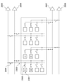
次に、ISO感度補正の第1の例について説明する。図8は、アナログゲインの第1の例を示す図である。図8(A)は、理想的なアナログゲインの一例を示す図である。図8(B)は、実際のアナログゲインの一例を示す図である。アナログゲインは、列アンプとランプとの組み合わせにより決定される。図8(B)に示されるアナログゲインは、図8(A)のアナログゲインに対してばらつきが生じている。このため、補正部704は、アナログゲインを補正する。 Next, a first example of ISO sensitivity correction will be described. FIG. 8 is a diagram showing a first example of analog gain. FIG. 8A is a diagram showing an example of an ideal analog gain. FIG. 8B is a diagram showing an example of an actual analog gain. The analog gain is determined by the combination of the column amplifier and the lamp. The analog gain shown in FIG. 8B has a variation with respect to the analog gain shown in FIG. 8A. Therefore, the correction unit 704 corrects the analog gain.

例えば、ISO1に着目した場合、図8(A)の例に示されるように、列アンプが「0.6倍」であり、ランプが「0.85倍」である場合のアナログゲイン「0.51倍(=0.6×0.85)」が理想値である。一方、実際のアナログゲインは、図8(B)の例では、列アンプが「0.59倍」であり、ランプが「0.84倍」であるため、アナログゲインは、「0.50倍(=0.59×0.84)」である。従って、ISO1についてのISO感度補正の補正値は、「1.02倍(=0.51/0.50)」である。 For example, when focusing on ISO 1, as shown in the example of FIG. 8A, the analog gain “0.” when the column amplifier is “0.6 times” and the lamp is “0.85 times”. 51 times (= 0.6 × 0.85) ”is the ideal value. On the other hand, in the example of FIG. 8B, the actual analog gain is "0.59 times" for the column amplifier and "0.84 times" for the lamp, so that the analog gain is "0.50 times". (= 0.59 × 0.84) ”. Therefore, the correction value of the ISO sensitivity correction for ISO1 is "1.02 times (= 0.51 / 0.50)".

ISO9に着目した場合、図8(A)の例に示されるように、列アンプが「8.0倍」であり、ランプが「1.00倍」である場合のアナログゲイン「8.00倍(=8.0×1.00)」が理想値である。一方、実際のアナログゲインは、図8(B)の例では、列アンプが「7.88倍」であり、ランプが「0.97倍」であるため、アナログゲインは、「7.64倍(=7.88×0.97)」である。従って、ISO1についてのISO感度補正の補正値は、「1.047倍(=8.00/7.64)」である。 Focusing on ISO9, as shown in the example of FIG. 8A, the analog gain “8.00 times” when the column amplifier is “8.0 times” and the lamp is “1.00 times”. (= 8.0 × 1.00) ”is the ideal value. On the other hand, in the example of FIG. 8B, the actual analog gain is "7.88 times" for the column amplifier and "0.97 times" for the lamp, so that the analog gain is "7.64 times". (= 7.88 × 0.97) ”. Therefore, the correction value of the ISO sensitivity correction for ISO1 is "1.047 times (= 8.00 / 7.64)".

以上のように、ISO感度ごとにISO感度補正の補正値が異なる。そこで、補正部704は、教師画像から抽出されたメタデータのISO感度情報に対応した補正値でISO感度補正を行う。ROM106には、ISO感度ごとのISO感度補正の補正値が記憶されている。ISO感度ごとのISO感度補正の補正値は、RAM107やストレージ装置140等に記憶されていてもよい。図8(B)の例では、実際のアナログゲインが理想的なアナログゲインよりも低い例を示しているが、実際のアナログゲインは理想的なアナログゲインよりも高くてもよい。 As described above, the correction value of the ISO sensitivity correction is different for each ISO sensitivity. Therefore, the correction unit 704 performs ISO sensitivity correction with a correction value corresponding to the ISO sensitivity information of the metadata extracted from the teacher image. The ROM 106 stores the correction value of the ISO sensitivity correction for each ISO sensitivity. The correction value of the ISO sensitivity correction for each ISO sensitivity may be stored in the RAM 107, the storage device 140, or the like. Although the example of FIG. 8B shows an example in which the actual analog gain is lower than the ideal analog gain, the actual analog gain may be higher than the ideal analog gain.

次に、ISO感度補正の第2の例について説明する。図9は、アナログゲインの第2の例を示す図である。図9に示されるアナログゲインは、温度により特性にばらつきがある。このため、ISO感度補正の補正値も温度により異なる。これは、チャンネルアンプの温度特性に起因している。そこで、ROM106は、各ISO感度と各温度との組み合わせごとに補正値を記憶してもよい。 Next, a second example of ISO sensitivity correction will be described. FIG. 9 is a diagram showing a second example of analog gain. The characteristics of the analog gain shown in FIG. 9 vary depending on the temperature. Therefore, the correction value of the ISO sensitivity correction also differs depending on the temperature. This is due to the temperature characteristics of the channel amplifier. Therefore, the ROM 106 may store the correction value for each combination of each ISO sensitivity and each temperature.

ここで、ROM106が全ての温度についての補正値を記憶する場合、ROM106に記憶される補正値の数も多くなる。この場合、各ISO感度と各温度との組み合わせの数が多くなり、パラメータ保存領域208に保存されるパラメータの数も多くなる。その結果、パラメータ保存領域208のために使用されるデータ量が大きくなる。そこで、ROM106は、所定範囲ごとの温度の補正値を纏めて記憶してもよい。 Here, when the ROM 106 stores the correction values for all the temperatures, the number of the correction values stored in the ROM 106 also increases. In this case, the number of combinations of each ISO sensitivity and each temperature increases, and the number of parameters stored in the parameter storage area 208 also increases. As a result, the amount of data used for the parameter storage area 208 is large. Therefore, the ROM 106 may collectively store the temperature correction values for each predetermined range.

例えば、ROM106は、第1温度範囲(0℃未満の低温)と第2温度範囲(0℃~40℃の温度)と第3温度範囲(40℃を超える高温)との3種類の温度範囲ごとに共通の補正値を記憶してもよい。上記のように各ISOのそれぞれについて3種類の温度範囲の補正値が用いられる場合、合計で33個(=11×3)の補正値がROM106に記憶される。これにより、複数の温度(例えば、0℃~40℃)については、共通の1つの補正値が用いられるため、パラメータ保存領域208に保存されるパラメータの数を削減でき、データ使用量を小さくすることができる。なお、温度範囲の設定方法や種類数等は上記の例には限定されない。例えば、温度範囲は、温度によるアナログゲインの変化の度合いに応じて、可変に設定されてもよい。この場合、上記の変化の度合いが所定度合い以上の区間では温度範囲が狭く設定され、所定度合い未満の区間では温度範囲が広く設定されてもよい。 For example, the ROM 106 has three types of temperature ranges: a first temperature range (low temperature less than 0 ° C.), a second temperature range (temperature of 0 ° C. to 40 ° C.), and a third temperature range (high temperature exceeding 40 ° C.). A common correction value may be stored in. When the correction values in the three types of temperature ranges are used for each of the ISOs as described above, a total of 33 correction values (= 11 × 3) are stored in the ROM 106. As a result, since one common correction value is used for a plurality of temperatures (for example, 0 ° C to 40 ° C), the number of parameters stored in the parameter storage area 208 can be reduced, and the amount of data used can be reduced. be able to. The temperature range setting method, the number of types, and the like are not limited to the above examples. For example, the temperature range may be set variably according to the degree of change in analog gain due to temperature. In this case, the temperature range may be set narrow in the section where the degree of change is equal to or greater than the predetermined degree, and the temperature range may be set wide in the section where the degree of change is less than the predetermined degree.

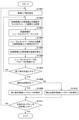
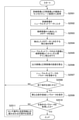
次に、第1の実施形態における学習処理の流れの一例について説明する。図10は、第1の実施形態の学習処理の流れの一例を示すフローチャートである。図10のフローチャートは、図7(A)のブロック図に対応する。S1001で、制御部209は、訓練画像および教師画像のペア(学習セット)をストレージ装置301から取得する。S1001の処理は、図3のS301の処理に対応する。S1002で、制御部209は、取得した複数の学習セットのうち1つの学習セットの訓練画像をニューラルネットワーク204に入力する。ニューラルネットワーク204が行う処理により、出力画像が生成される。S1002の処理は、図3のS302の処理に対応する。 Next, an example of the flow of the learning process in the first embodiment will be described. FIG. 10 is a flowchart showing an example of the flow of the learning process of the first embodiment. The flowchart of FIG. 10 corresponds to the block diagram of FIG. 7 (A). In S1001, the control unit 209 acquires a pair (learning set) of the training image and the teacher image from the storage device 301. The process of S1001 corresponds to the process of S301 of FIG. In S1002, the control unit 209 inputs the training image of one of the acquired learning sets to the neural network 204. The output image is generated by the process performed by the neural network 204. The process of S1002 corresponds to the process of S302 in FIG.

S1003で、画像処理部205の抽出部702は、教師画像からメタデータを抽出する。S1004で、補正値取得部703は、抽出されたメタデータのISO感度情報と温度情報との組み合わせに対応する補正値をROM106から取得する。S1005で、補正部704は、教師画像およびニューラルネットワーク204から出力された出力画像に対して、取得された補正値でISO感度補正を行う。ニューラルネットワーク204から出力された出力画像は、訓練画像に対してニューラルネットワーク204の処理が行われた画像である。 In S1003, the extraction unit 702 of the image processing unit 205 extracts metadata from the teacher image. In S1004, the correction value acquisition unit 703 acquires the correction value corresponding to the combination of the ISO sensitivity information and the temperature information of the extracted metadata from the ROM 106. In S1005, the correction unit 704 performs ISO sensitivity correction on the teacher image and the output image output from the neural network 204 with the acquired correction value. The output image output from the neural network 204 is an image obtained by processing the training image with the neural network 204.

S1006で、誤差評価部206は、誤差評価部206は、画像処理がされた出力画像と教師画像との誤差を算出する。S1006の処理は、図3のS304の処理に対応する。S1007で、パラメータ調整部207は、算出した誤差が小さくなるように、誤差逆伝播法を用いて、ニューラルネットワーク204の各パラメータを更新する。S1006の処理は、図3のS305の処理に対応する。S1008で、制御部209は、所定の終了条件を満たしたかを判定する。S1008の処理は、図3のS306の処理に対応する。制御部209は、S1008でNOと判定した場合、所定の終了条件を満たしていないため、フローをS1001に戻す。一方、制御部209は、S1008でYESと判定した場合、所定の終了条件を満たしたため、フローをS1009に進める。 In S1006, the error evaluation unit 206 calculates the error between the image-processed output image and the teacher image. The process of S1006 corresponds to the process of S304 of FIG. In S1007, the parameter adjusting unit 207 updates each parameter of the neural network 204 by using the error back propagation method so that the calculated error becomes small. The process of S1006 corresponds to the process of S305 of FIG. In S1008, the control unit 209 determines whether or not the predetermined end condition is satisfied. The process of S1008 corresponds to the process of S306 in FIG. When the control unit 209 determines NO in S1008, the control unit 209 returns the flow to S1001 because the predetermined end condition is not satisfied. On the other hand, if the control unit 209 determines YES in S1008, the control unit 209 satisfies the predetermined end condition, so that the flow proceeds to S1009.

S1009で、制御部209は、更新されたパラメータ(学習済みのパラメータ)を、ISO感度補正の補正条件ごとに異なるパラメータ保存領域208に保存する。本実施形態のISO感度補正の補正条件は、各ISO感度と各温度範囲との組み合わせに対応する補正値である。温度情報が用いられない場合、本実施形態のISO感度補正の補正条件は、各ISO感度に対応する補正値である。制御部209は、更新されたパラメータを、各ISO感度と各温度範囲との組み合わせごとに異なるパラメータ保存領域208に保存する。S1009の処理は、図3のS307に対応する。S1010で、制御部209は、全ての条件のパラメータを取得したかを判定する。このとき、制御部209は、各ISOと各温度範囲とについて全ての組み合わせを取得したかに基づいて、S1010の判定を行う。制御部209は、S1010でYESと判定した場合、図10のフローチャートの処理を終了させる。一方、制御部209は、S1010でNOと判定した場合、フローをS1011に進める。S1011で、制御部209は、ISOと温度範囲との組み合わせの条件を変更する。そして、制御部209は、フローをS1001に戻す。これにより、ISOと温度範囲との組み合わせを変更した学習処理が新たに行われる。 In S1009, the control unit 209 stores the updated parameter (learned parameter) in the parameter storage area 208 that is different for each correction condition of the ISO sensitivity correction. The correction condition for the ISO sensitivity correction of the present embodiment is a correction value corresponding to the combination of each ISO sensitivity and each temperature range. When the temperature information is not used, the correction condition for the ISO sensitivity correction of the present embodiment is a correction value corresponding to each ISO sensitivity. The control unit 209 stores the updated parameters in a parameter storage area 208 that is different for each combination of ISO sensitivity and each temperature range. The processing of S1009 corresponds to S307 of FIG. In S1010, the control unit 209 determines whether or not the parameters of all the conditions have been acquired. At this time, the control unit 209 determines S1010 based on whether all combinations of each ISO and each temperature range have been acquired. If the control unit 209 determines YES in S1010, the control unit 209 ends the processing of the flowchart of FIG. On the other hand, when the control unit 209 determines NO in S1010, the control unit 209 advances the flow to S1011. In S1011, the control unit 209 changes the conditions for the combination of ISO and the temperature range. Then, the control unit 209 returns the flow to S1001. As a result, a learning process in which the combination of ISO and the temperature range is changed is newly performed.

次に、第1の実施形態における処理の流れの他の例について説明する。図11は、第1の実施形態の学習処理の流れの他の例を示すフローチャートである。図11のフローチャートは、図7(B)のブロック図に対応する。図10のフローチャートの処理では、ニューラルネットワーク204から出力された出力画像に対してISO感度補正が行われて、学習処理が行われる。一方、図11のフローチャートの処理では、ニューラルネットワーク204に入力される訓練画像に対してISO感度補正が行われて、学習処理が行われる。 Next, another example of the processing flow in the first embodiment will be described. FIG. 11 is a flowchart showing another example of the flow of the learning process of the first embodiment. The flowchart of FIG. 11 corresponds to the block diagram of FIG. 7 (B). In the processing of the flowchart of FIG. 10, ISO sensitivity correction is performed on the output image output from the neural network 204, and learning processing is performed. On the other hand, in the processing of the flowchart of FIG. 11, ISO sensitivity correction is performed on the training image input to the neural network 204, and learning processing is performed.

S1101の処理は、S1001の処理に対応する。S1102で、画像処理部205の抽出部702は、教師画像からメタデータを抽出する。S1103で、補正値取得部703は、抽出されたメタデータのISO感度情報と温度情報との組み合わせに対応する補正値をROM106から取得する。S1102の処理はS1003の処理に対応し、S1103の処理はS1004の処理に対応する。S1104で、補正部704は、教師画像および訓練画像に対してISO感度補正を行う。つまり、補正部704は、ニューラルネットワーク204の処理がされていない訓練画像に対してISO感度補正を行う。 The process of S1101 corresponds to the process of S1001. In S1102, the extraction unit 702 of the image processing unit 205 extracts metadata from the teacher image. In S1103, the correction value acquisition unit 703 acquires the correction value corresponding to the combination of the ISO sensitivity information and the temperature information of the extracted metadata from the ROM 106. The process of S1102 corresponds to the process of S1003, and the process of S1103 corresponds to the process of S1004. In S1104, the correction unit 704 performs ISO sensitivity correction on the teacher image and the training image. That is, the correction unit 704 performs ISO sensitivity correction on the training image that has not been processed by the neural network 204.

S1105で、制御部209は、ISO感度補正がされた訓練画像をニューラルネットワーク204に入力する。ISO感度補正がされた訓練画像を入力として、ニューラルネットワーク204が行う処理により、出力画像が生成される。S1106で、誤差評価部206は、ISO感度補正がされた教師画像とS1105で生成された出力画像との誤差を算出する。S1107で、パラメータ調整部207は、算出した誤差が小さくなるように、誤差逆伝播法を用いて、ニューラルネットワーク204の各パラメータを更新する。S1108~S1111の各処理は、図10のS1008~S1011の各処理と同様であるため、説明を省略する。 In S1105, the control unit 209 inputs the training image corrected for ISO sensitivity to the neural network 204. An output image is generated by a process performed by the neural network 204 with the training image corrected for ISO sensitivity as an input. In S1106, the error evaluation unit 206 calculates the error between the ISO sensitivity-corrected teacher image and the output image generated in S1105. In S1107, the parameter adjusting unit 207 updates each parameter of the neural network 204 by using the error back propagation method so that the calculated error becomes small. Since each process of S1108 to S1111 is the same as each process of S1008 to S1011 of FIG. 10, the description thereof will be omitted.

図10のフローチャートおよび図11のフローチャートは、第1の実施形態のISO感度情報と温度情報との組み合わせに関する学習処理の流れを示す。図10のS1004または図11のS1103で、補正値取得部703は、抽出されたメタデータのISO感度情報と温度情報との組み合わせに対応する補正値をROM106から取得している。このとき、補正値取得部703は、ROM106からISO感度情報を取得し、温度情報を取得しなくてもよい。例えば、ROM106にISO感度情報が記憶されていない場合、補正値取得部703は、ROM106からISO感度情報を取得し、温度情報を取得しない。この場合でも、各ISOのそれぞれの補正値を用いて、ISO感度補正を行うことができる。 The flowchart of FIG. 10 and the flowchart of FIG. 11 show the flow of the learning process regarding the combination of the ISO sensitivity information and the temperature information of the first embodiment. In S1004 of FIG. 10 or S1103 of FIG. 11, the correction value acquisition unit 703 acquires the correction value corresponding to the combination of the ISO sensitivity information and the temperature information of the extracted metadata from the ROM 106. At this time, the correction value acquisition unit 703 does not have to acquire the ISO sensitivity information from the ROM 106 and acquire the temperature information. For example, when the ISO sensitivity information is not stored in the ROM 106, the correction value acquisition unit 703 acquires the ISO sensitivity information from the ROM 106 and does not acquire the temperature information. Even in this case, the ISO sensitivity correction can be performed using the respective correction values of each ISO.

次に、第1の実施形態の推論処理について説明する。図12は、第1の実施形態の推論処理の流れの一例を示すフローチャートである。S1201で、取得部501は、ISO感度情報および温度情報を取得する。取得部501は、撮像装置120からISO感度情報および温度情報を取得することができる。例えば、撮像装置120の設定条件に基づいて、取得部501はISO感度情報を取得することができる。また、撮像装置120がサーミスタのような温度測定機能を有している場合、取得部501は、撮像装置120のサーミスタが測定した温度から温度情報を取得することができる。取得部501は、ストレージ装置140に記憶されている画像データのメタデータからISO感度情報および温度情報を取得してもよい。 Next, the inference processing of the first embodiment will be described. FIG. 12 is a flowchart showing an example of the flow of the inference processing of the first embodiment. In S1201, the acquisition unit 501 acquires ISO sensitivity information and temperature information. The acquisition unit 501 can acquire ISO sensitivity information and temperature information from the image pickup apparatus 120. For example, the acquisition unit 501 can acquire ISO sensitivity information based on the setting conditions of the image pickup apparatus 120. Further, when the image pickup apparatus 120 has a temperature measurement function such as that of a thermistor, the acquisition unit 501 can acquire temperature information from the temperature measured by the thermistor of the image pickup apparatus 120. The acquisition unit 501 may acquire ISO sensitivity information and temperature information from the metadata of the image data stored in the storage device 140.

S1202で、パラメータ選択部502は、取得したISO感度情報と温度情報との組み合わせに対応するパラメータを、パラメータ保存領域208-1~208-nから選択する。S1203で、制御部504は、選択されたパラメータをニューラルネットワーク204に適用する。これにより、ニューラルネットワーク204による推論処理を行うことが可能な状態になる。S1204~S1207の各処理は、図6のS604~S607と同じであるため、説明を省略する。 In S1202, the parameter selection unit 502 selects the parameter corresponding to the combination of the acquired ISO sensitivity information and the temperature information from the parameter storage areas 208-1 to 208-n. In S1203, the control unit 504 applies the selected parameter to the neural network 204. As a result, it becomes possible to perform inference processing by the neural network 204. Since each process of S1204 to S1207 is the same as S604 to S607 of FIG. 6, the description thereof will be omitted.

第1の実施形態では、パラメータ保存領域208―1~208-nに、各ISO感度のそれぞれに応じて学習処理がされたニューラルネットワーク204のパラメータが保存される。そして、パラメータ選択部502は、ISO感度の条件に基づいて、対応するパラメータを、パラメータ保存領域208―1~208-nから選択する。これにより、ISO感度の条件に合ったパラメータを用いた撮像画像の推論処理を行うことができるため、推論精度が向上する。その結果、ノイズを低減した画像を得ることができる。また、第1の実施形態では、温度条件も加味した学習処理が行われる。つまり、パラメータ保存領域208―1~208-nに、各ISOと各温度範囲との組み合わせのそれぞれに応じて学習処理がされたニューラルネットワーク204のパラメータが保存することもできる。そして、パラメータ選択部502は、ISO感度と温度との両者の条件に基づいて、対応するパラメータを、パラメータ保存領域208―1~208-nから選択する。これにより、ISO感度の特性と温度の特性とに合ったパラメータを用いた撮像画像の推論処理を行うことができるため、より推論精度を向上させることができる。その結果、画像のノイズの低減効果をさらに向上させることができる。 In the first embodiment, the parameters of the neural network 204 that have been trained according to each ISO sensitivity are stored in the parameter storage areas 208-1 to 208-n. Then, the parameter selection unit 502 selects the corresponding parameter from the parameter storage areas 208-1 to 208-n based on the ISO sensitivity condition. As a result, the inference processing of the captured image can be performed using the parameters that match the ISO sensitivity conditions, so that the inference accuracy is improved. As a result, it is possible to obtain an image with reduced noise. Further, in the first embodiment, the learning process is performed in consideration of the temperature condition. That is, the parameters of the neural network 204 that have been trained according to the combination of each ISO and each temperature range can be stored in the parameter storage areas 208-1 to 208-n. Then, the parameter selection unit 502 selects the corresponding parameter from the parameter storage areas 208-1 to 208-n based on both the ISO sensitivity and the temperature conditions. As a result, it is possible to perform inference processing of the captured image using parameters that match the ISO sensitivity characteristics and the temperature characteristics, so that the inference accuracy can be further improved. As a result, the noise reduction effect of the image can be further improved.

(第2の実施形態)
第2の実施形態では、画像処理としてF値補正を例にあげ、複数のF値補正のそれぞれに対応する補正値でF値補正が施された教師画像と訓練画像とを用いて学習処理が行われた学習モデルのパラメータの具体例について説明する。
(Second embodiment)
In the second embodiment, F-number correction is taken as an example of image processing, and learning processing is performed using a teacher image and a training image in which F-number correction is performed with correction values corresponding to each of a plurality of F-number corrections. A specific example of the parameters of the training model performed will be described.

F値補正は、絞り値であるF値と光量(輝度)との関係が線形とならない場合に、F値と光量(輝度)との関係が線形に近づくように画像にゲインを適用する補正である。図13は、第2の実施形態におけるF値と光量との関係、および、F値と補正値との関係の一例を示すグラフである。図13(A)は、F値と光量との関係を示すグラフである。横軸はF値であり、縦軸は撮像装置120の撮像素子122が受光した光量を示す。上述したように、F値補正は、レンズユニット121の絞り値(F値)に応じて、ゲインを施す処理である。ここで、絞りを小絞り側から開放側に変化させたとき、小絞り側ではF値と光量(輝度)との関係は線形な関係になるが、開放側ではF値と光量(輝度)との関係は非線形な関係になる。開放側ではF値と光量(輝度)との関係が非線形な関係になる要因の1つとしては、開放側では撮像素子122に対して斜めから入射する光を十分に取り込めないことがある。そこで、F値が開放側の区間では、理想的な線形に近づけるために画像信号にゲインを乗じるF値補正が施される。開放側の区間では、F値補正が施されるため、画像にノイズが生じる。 F-number correction is a correction that applies gain to an image so that the relationship between the F-number and the amount of light (luminance) approaches linear when the relationship between the F-number, which is the aperture value, and the amount of light (luminance) is not linear. be. FIG. 13 is a graph showing an example of the relationship between the F value and the amount of light and the relationship between the F value and the correction value in the second embodiment. FIG. 13A is a graph showing the relationship between the F value and the amount of light. The horizontal axis is the F value, and the vertical axis shows the amount of light received by the image pickup device 122 of the image pickup device 120. As described above, the F value correction is a process of applying a gain according to the aperture value (F value) of the lens unit 121. Here, when the aperture is changed from the small aperture side to the open side, the relationship between the F value and the amount of light (luminance) is linear on the small aperture side, but the F value and the amount of light (luminance) are on the open side. The relationship is non-linear. One of the factors that causes the relationship between the F value and the amount of light (luminance) to be non-linear on the open side is that the light incident on the image sensor 122 from an angle cannot be sufficiently captured on the open side. Therefore, in the section where the F value is on the open side, F value correction is performed by multiplying the image signal by the gain in order to approach the ideal linearity. In the section on the open side, the F value is corrected, so that noise is generated in the image.

図13(A)では、F値が、Fx~Fsの区間におけるF値と光量との関係は、実線で表されるように線形に変化する。一方、Fe~Fxの区間におけるF値と光量との関係は、一点鎖線で表されるように非線形に変化する。そこで、上述したように、F値と光量との関係が非線形な区間でも線形となるように、Fe~Fxの区間(以下、非線形な区間)にノイズを除去するための補正値が乗じられる。非線形な区間における補正値は、図13(A)および図13(B)に示されるように一定の値ではない。一方、Fx~Fsの区間(以下、線形の区間)には、一定の値の補正値が乗じられる。つまり、非線形な区間の補正値は、F値と光量との関係が線形となるように、F値によって適正な値に変化させる必要がある。図13(B)では、非線形の区間の補正値が点線で示されている。 In FIG. 13A, the relationship between the F value and the amount of light in the section of Fx to Fs changes linearly as shown by the solid line. On the other hand, the relationship between the F value and the amount of light in the section from Fe to Fx changes non-linearly as represented by the alternate long and short dash line. Therefore, as described above, a correction value for removing noise is multiplied in the section from Fe to Fx (hereinafter referred to as the non-linear section) so that the relationship between the F value and the amount of light is linear even in the non-linear section. The correction value in the non-linear interval is not a constant value as shown in FIGS. 13 (A) and 13 (B). On the other hand, a correction value of a certain value is multiplied in the section from Fx to Fs (hereinafter, linear section). That is, the correction value of the non-linear section needs to be changed to an appropriate value depending on the F value so that the relationship between the F value and the amount of light becomes linear. In FIG. 13B, the correction value of the non-linear section is shown by the dotted line.

次に第2の実施形態における学習処理の流れの一例について説明する。図14は、第2の実施形態の学習処理の流れの一例を示すフローチャートである。図14のフローチャートは、図7(A)のブロック図に対応し、画像処理部205の補正部704がF値補正を行う。S1401で、制御部209は、学習処理を行う際のF値を新規に設定する。S1402で、制御部209は、訓練画像および教師画像のペア(学習セット)をストレージ装置301から取得する。S1403で、制御部209は、取得した複数の学習セットのうち1つの学習セットの訓練画像をニューラルネットワーク204に入力する。ニューラルネットワーク204が行う処理により、出力画像が生成される。訓練画像のノイズ量やノイズパターンは、他の訓練画像のノイズ量やノイズパターンと異なっている場合もあり、同じ場合もある。 Next, an example of the flow of the learning process in the second embodiment will be described. FIG. 14 is a flowchart showing an example of the flow of the learning process of the second embodiment. The flowchart of FIG. 14 corresponds to the block diagram of FIG. 7A, and the correction unit 704 of the image processing unit 205 corrects the F value. In S1401, the control unit 209 newly sets the F value when performing the learning process. In S1402, the control unit 209 acquires a pair (learning set) of the training image and the teacher image from the storage device 301. In S1403, the control unit 209 inputs the training image of one of the acquired learning sets to the neural network 204. The output image is generated by the process performed by the neural network 204. The noise amount and noise pattern of the training image may be different from the noise amount and noise pattern of other training images, and may be the same.

S1404で、画像処理部205は、教師画像とニューラルネットワーク204からの出力画像とに対してF値補正を行う。このとき、画像処理部205は、S1401で設定されたF値に応じた補正値でF値補正を行う。上述したように、画像処理部205は、図2(A)に示すようにニューラルネットワーク204の出力側にあってもよいし、図2(B)に示すように入力側にあってもよい。つまり、S1401の処理は、S1403の処理より前に行われてもよい。なお、画像処理部205の抽出部702が、教師画像のメタデータからF値を取得する構成とすれば、S1401を省略することができる。S1405で、誤差評価部206は、F値補正がされた出力画像と教師画像との誤差を算出する。S1406で、パラメータ調整部207は、算出した誤差が小さくなるように、誤差逆伝播法を用いて、ニューラルネットワーク204の各パラメータを更新する。S1407で、制御部209は、所定の終了条件を満たしたかを判定する。制御部209は、S1407でNOと判定した場合、フローをS1402に戻す。この場合、新たな訓練画像と正解画像との学習セットを用いて、S1402~S1406の処理が行われる。一方、制御部209は、S1407でYESと判定した場合、フローをS1408に進める。 In S1404, the image processing unit 205 corrects the F value with respect to the teacher image and the output image from the neural network 204. At this time, the image processing unit 205 corrects the F value with the correction value corresponding to the F value set in S1401. As described above, the image processing unit 205 may be on the output side of the neural network 204 as shown in FIG. 2A, or may be on the input side as shown in FIG. 2B. That is, the processing of S1401 may be performed before the processing of S1403. If the extraction unit 702 of the image processing unit 205 acquires the F value from the metadata of the teacher image, S1401 can be omitted. In S1405, the error evaluation unit 206 calculates the error between the output image corrected for the F value and the teacher image. In S1406, the parameter adjustment unit 207 updates each parameter of the neural network 204 by using the error back propagation method so that the calculated error becomes small. In S1407, the control unit 209 determines whether or not the predetermined end condition is satisfied. When the control unit 209 determines NO in S1407, the control unit 209 returns the flow to S1402. In this case, the processing of S1402 to S1406 is performed using the learning set of the new training image and the correct answer image. On the other hand, if the control unit 209 determines YES in S1407, the control unit 209 advances the flow to S1408.

S1408で、制御部209は、S1401で設定したF値が線形な区間にあるかを判定する。線形な区間については後述する。制御部209は、S1408でYESと判定した場合、フローをS1409に進める。S1409で、制御部209は、更新されたパラメータ(学習済みのパラメータ)を同じパラメータ保存領域208に保存する。一方、制御部209は、S1408でNOと判定した場合、フローをS1410に進める。S1410で、制御部209は、更新されたパラメータ(学習済みのパラメータ)を、S1401で設定されたF値に応じて、異なるパラメータ保存領域208に保存する。S1409およびS1410で、制御部209は、機械学習により更新されたパラメータやニューラルネットワーク204のモデル構造等に関する情報をS1401で設定したF値の条件と関連付けて、パラメータ保存領域208に保存してもよい。S1411で、制御部209は、全てのF値の条件についてのパラメータを取得したかを判定する。制御部209は、S1411でNOと判定した場合、フローをS1401に戻し、新規にF値の条件を設定する。制御部209は、S1411でYESと判定した場合、図14のフローチャートの処理を終了させる。 In S1408, the control unit 209 determines whether the F value set in S1401 is in the linear section. The linear section will be described later. If the control unit 209 determines YES in S1408, the control unit 209 advances the flow to S1409. In S1409, the control unit 209 stores the updated parameter (learned parameter) in the same parameter storage area 208. On the other hand, if the control unit 209 determines NO in S1408, the control unit 209 advances the flow to S1410. In S1410, the control unit 209 stores the updated parameter (learned parameter) in a different parameter storage area 208 according to the F value set in S1401. In S1409 and S1410, the control unit 209 may store the information related to the parameters updated by machine learning, the model structure of the neural network 204, etc. in the parameter storage area 208 in association with the F value condition set in S1401. .. In S1411, the control unit 209 determines whether or not the parameters for all the F value conditions have been acquired. When the control unit 209 determines NO in S1411, the flow is returned to S1401 and a new F value condition is set. If the control unit 209 determines YES in S1411, the control unit 209 ends the processing of the flowchart of FIG.

このように、制御部209は、補正するF値を変化させて、ニューラルネットワーク204の機械学習(ディープラーニング)を実施させる制御を行う。これにより、F値ごとの補正値を反映して機械学習がされ、パラメータが更新される。そして、図14のS1408で、制御部209は、機械学習を行う際に設定されたF値が線形の区間内であるかを判定する。制御部209は、例えば、設定されたF値が上述したFx以上であるかに基づいて、S1408の判定を行うことができる。Fxの値(所定の閾値)は任意の値に設定されてよいが、F値と光量との関係が線形から非線形に変化する境界に設定されることが好ましい。ただし、Fxの値は、境界から所定範囲内の値に設定されてもよい。 In this way, the control unit 209 controls to perform machine learning (deep learning) of the neural network 204 by changing the F value to be corrected. As a result, machine learning is performed reflecting the correction value for each F value, and the parameters are updated. Then, in S1408 of FIG. 14, the control unit 209 determines whether the F value set when performing machine learning is within the linear section. The control unit 209 can determine S1408, for example, based on whether the set F value is equal to or greater than the above-mentioned Fx. The value of Fx (predetermined threshold value) may be set to an arbitrary value, but it is preferably set to the boundary where the relationship between the F value and the amount of light changes from linear to non-linear. However, the value of Fx may be set to a value within a predetermined range from the boundary.

そして、制御部209は、S1408でYESと判定した場合、更新された学習済みのパラメータをパラメータ保存領域208-1~208-nのうち同じパラメータ保存領域208に保存する。制御部209は、異なるF値についての更新されたパラメータであっても、S1408でYESと判定した場合、同じパラメータ保存領域208-1に保存する。または、制御部209は、S1408でYESと判定した場合、更新されたパラメータを1度保存したのであれば、2回目以降は、S1409の処理を省略してもよい。一方、制御部209は、S1408でNOと判定した場合、異なるF値を設定して、更新された学習済みのパラメータをそれぞれ異なるパラメータ保存領域208に保存する。制御部209は、S1410の処理を実行するごとに、順次、異なるパラメータ保存領域208(例えば、パラメータ保存領域208-2~208-n)に保存する。 Then, when the control unit 209 determines YES in S1408, the control unit 209 stores the updated learned parameter in the same parameter storage area 208 of the parameter storage areas 208-1 to 208-n. If the control unit 209 determines YES in S1408 even if the updated parameters have different F values, the control unit 209 stores them in the same parameter storage area 208-1. Alternatively, when the control unit 209 determines YES in S1408, if the updated parameter is saved once, the processing of S1409 may be omitted from the second time onward. On the other hand, when the control unit 209 determines NO in S1408, a different F value is set and the updated learned parameters are stored in different parameter storage areas 208. Each time the process of S1410 is executed, the control unit 209 sequentially stores the parameters in different parameter storage areas 208 (for example, parameter storage areas 208-2 to 208-n).

従って、F値と光量(輝度)とが非線形な関係になる区間においては、細かい粒度のF値に応じたニューラルネットワーク204のパラメータを用いて、推論処理を実行することができる。これにより、推論精度が向上する。一方、F値と光量(輝度)とが線形な区間においては、1つのニューラルネットワーク204のパラメータを用いて、推論処理が実行される。これにより、保存するパラメータの数を削減できることから、データの使用量を低減できるとともに、ストレージ装置140やRAM107等のハードウェア資源の使用量を低減できる。つまり、画像処理装置100は、F値に応じて、保存するパラメータの粒度を変更していることから、推論精度が低下することを抑制しつつ、データの使用量を削減することができる。 Therefore, in the section where the F value and the amount of light (luminance) have a non-linear relationship, the inference process can be executed by using the parameters of the neural network 204 corresponding to the F value having a fine grain size. This improves the inference accuracy. On the other hand, in the section where the F value and the amount of light (luminance) are linear, the inference process is executed using one parameter of the neural network 204. As a result, the number of parameters to be stored can be reduced, so that the amount of data used can be reduced and the amount of hardware resources such as the storage device 140 and RAM 107 can be reduced. That is, since the image processing apparatus 100 changes the particle size of the parameter to be stored according to the F value, it is possible to reduce the amount of data used while suppressing the deterioration of the inference accuracy.

上述した例では、画像処理装置100は、非線形な区間では、F値ごとに、機械学習されたニューラルネットワーク204のパラメータを保存しているが、この例には限定されない。画像処理装置100は、例えば、非線形な区間では、撮像装置120のレンズユニット121に設けられた絞りの駆動分解能ごとに、学習済みのパラメータを保存してもよい。また、画像処理装置100は学習処理と推論処理との両方を行っている。この点、学習処理を行う画像処理装置と推論処理を行う画像処理装置とは別個の装置であってもよい。この点は、第1の実施形態と同様である。学習処理を行う画像処理装置と推論処理を行う画像処理装置とが別個の装置である例は、以下の各実施形態でも同様である。 In the above-mentioned example, the image processing apparatus 100 stores the parameters of the machine-learned neural network 204 for each F value in the non-linear section, but the present invention is not limited to this example. For example, in a non-linear section, the image processing device 100 may store learned parameters for each drive resolution of the diaphragm provided in the lens unit 121 of the image pickup device 120. Further, the image processing apparatus 100 performs both learning processing and inference processing. In this respect, the image processing device that performs learning processing and the image processing device that performs inference processing may be separate devices. This point is the same as that of the first embodiment. An example in which the image processing device that performs learning processing and the image processing device that performs inference processing are separate devices is the same in each of the following embodiments.

この場合、推論装置は、線形な区間では1つの学習済みのパラメータを取得して保存し、非線形な区間では複数の絞り値のそれぞれに応じた学習済みのパラメータを取得して保存する。そして、推論装置は、図6のフローチャートの各処理を行う。以上のように、学習処理を行う画像処理装置と推論処理を行う画像処理装置とは別個の装置であっても、同様の効果を得ることができる。 In this case, the inference device acquires and stores one trained parameter in the linear section, and acquires and stores the trained parameter corresponding to each of the plurality of aperture values in the non-linear section. Then, the inference device performs each process of the flowchart of FIG. As described above, the same effect can be obtained even if the image processing device that performs the learning process and the image processing device that performs the inference processing are separate devices.

次に、第2の実施形態の変形例について説明する。図15は、第2の実施形態の変形例におけるF値と補正値との関係の一例を示すグラフである。第1の実施形態では、F値がFx~Fsの区間における補正値は一定であったが、第2実施形態では、F値がFx~Fsの区間における補正値は線形に変化する。F値がFx~Fsの区間は、F値と光量(輝度)との関係が線形の区間である。第2実施形態では、制御部209は、F値をFxに設定して図14の処理を行って得られたパラメータ(第1パラメータ)とF値をFsに設定して図14の処理を行って得られたパラメータ(第2パラメータ)とを、パラメータ保存領域208に保存する。 Next, a modified example of the second embodiment will be described. FIG. 15 is a graph showing an example of the relationship between the F value and the correction value in the modified example of the second embodiment. In the first embodiment, the correction value in the section where the F value is Fx to Fs is constant, but in the second embodiment, the correction value in the section where the F value is Fx to Fs changes linearly. The section where the F value is Fx to Fs is a section in which the relationship between the F value and the amount of light (luminance) is linear. In the second embodiment, the control unit 209 sets the F value to Fx and performs the processing of FIG. 14, and sets the parameter (first parameter) obtained by performing the processing of FIG. 14 and the F value to Fs, and performs the processing of FIG. The obtained parameter (second parameter) is stored in the parameter storage area 208.

そして、図15に示されるように、F値がFzの場合の撮像画像の推論処理が行われる場合には、制御部504は、第1パラメータを用いた推論画像と第2パラメータを用いた推論画像とを用いて補間する。これにより、補正値が線形に変化するFx~Fsの区間の任意のF値についての推論画像を得ることができる。この場合、Fx~Fsの区間の任意のF値についての推論画像を得るために保存されるパラメータ(機械学習されたパラメータ)は2つである。 Then, as shown in FIG. 15, when the inference processing of the captured image is performed when the F value is Fz, the control unit 504 infers using the inference image using the first parameter and the inference using the second parameter. Interpolate using an image. As a result, it is possible to obtain an inferred image for an arbitrary F value in the section of Fx to Fs in which the correction value changes linearly. In this case, there are two parameters (machine-learned parameters) stored in order to obtain an inferred image for an arbitrary F value in the section of Fx to Fs.

ここで、制御部504は、補正値が線形に変化するFx~Fsの区間における任意の2つのF値を用いて、図14の処理を行い、第1パラメータおよび第2パラメータを保存してもよい。この場合でも、第1パラメータを用いた推論画像と第2パラメータを用いた推論画像とを用いて補間することにより、補正値が線形に変化するFx~Fsの区間の任意のF値についての推論画像を得ることができる。 Here, even if the control unit 504 performs the processing of FIG. 14 using any two F values in the section of Fx to Fs in which the correction value changes linearly, and saves the first parameter and the second parameter. good. Even in this case, inference about an arbitrary F value in the interval of Fx to Fs in which the correction value changes linearly by interpolating using the inference image using the first parameter and the inference image using the second parameter. You can get an image.

図16は、第2の実施形態の変形における推論処理の流れの一例を示すフローチャートである。S1601で取得部501は、撮像装置120から、F値の情報を取得する。S1602で、制御部504は、S1601で取得された情報が示すF値が線形な区間内であるかを判定する。上述したように、制御部504は、S1601で取得された情報が示すF値がFx以上(所定の閾値以上)である場合には、S1602でNOと判定し、F値がFx未満(所定の閾値未満)である場合には、S1602でYESと判定してもよい。制御部504は、S1602でNOと判定した場合、S1603で、パラメータ選択部502は、取得したF値の情報に対応するパラメータを、パラメータ保存領域208-1~208-nから選択する。パラメータ保存領域208-1~208-nに保存されている各パラメータは、それぞれ異なるF値の条件で更新されたパラメータである。パラメータ選択部502は、取得したF値の情報と同じであるF値についてのパラメータまたは最も値が近いF値についてのパラメータを取得する。 FIG. 16 is a flowchart showing an example of the flow of inference processing in the modification of the second embodiment. In S1601, the acquisition unit 501 acquires F-number information from the image pickup apparatus 120. In S1602, the control unit 504 determines whether the F value indicated by the information acquired in S1601 is within a linear section. As described above, when the F value indicated by the information acquired in S1601 is Fx or more (predetermined threshold value or more), the control unit 504 determines NO in S1602, and the F value is less than Fx (predetermined). If it is less than the threshold value), it may be determined as YES in S1602. When the control unit 504 determines NO in S1602, the parameter selection unit 502 selects the parameter corresponding to the acquired F value information from the parameter storage areas 208-1 to 208-n in S1603. Each parameter stored in the parameter storage areas 208-1 to 208-n is a parameter updated under different F value conditions. The parameter selection unit 502 acquires a parameter for the F value that is the same as the acquired F value information or a parameter for the F value that is the closest to the value.

S1604で、制御部504は、選択されたパラメータをニューラルネットワーク204に適用する。これにより、ニューラルネットワーク204による推論処理を行うことが可能な状態になる。S1605で、取得部501は、撮像装置120から、撮像画像を取得する。この撮像画像は、RAW画像であるものとする。RAW画像に符号化処理が施されている場合、CPU105または画像処理回路103は、復号処理を行う。取得部501は、ストレージ装置140やROM106、RAM107等から、RAW画像を取得してもよい。 In S1604, the control unit 504 applies the selected parameter to the neural network 204. As a result, it becomes possible to perform inference processing by the neural network 204. In S1605, the acquisition unit 501 acquires an captured image from the image pickup device 120. This captured image is assumed to be a RAW image. When the RAW image is coded, the CPU 105 or the image processing circuit 103 performs the decoding process. The acquisition unit 501 may acquire RAW images from the storage device 140, ROM 106, RAM 107, and the like.

S1606で、制御部504は、取得した撮像画像をニューラルネットワーク204に入力する。S1607で、ニューラルネットワーク204は、推論処理を行う。ニューラルネットワーク204による推論処理は、GPU109により実行されてもよいし、CPU105により実行されてもよいし、CPU105とGPU109との協働動作により実行されてもよい。S1607の推論処理により、ニューラルネットワーク204の推論結果として推論画像が生成される。S1608で、推論画像出力部503は、生成された推論画像をストレージ装置140に出力する。推論画像出力部503は、生成された推論画像を、ROM106やRAM107、表示装置130等に出力してもよい。このとき、S1603で選択されるパラメータは、非線形な区間内のF値を用いて学習処理がされた学習済みのパラメータである。 In S1606, the control unit 504 inputs the acquired captured image to the neural network 204. In S1607, the neural network 204 performs inference processing. The inference process by the neural network 204 may be executed by the GPU 109, may be executed by the CPU 105, or may be executed by the cooperative operation of the CPU 105 and the GPU 109. The inference process of S1607 generates an inference image as an inference result of the neural network 204. In S1608, the inference image output unit 503 outputs the generated inference image to the storage device 140. The inference image output unit 503 may output the generated inference image to the ROM 106, the RAM 107, the display device 130, or the like. At this time, the parameter selected in S1603 is a trained parameter that has been trained using the F value in the non-linear interval.

制御部504は、S1602でNOと判定した場合、フローをS1609に進める。S1609で、パラメータ選択部502は、上述した第1パラメータを選択する。例えば、第1パラメータがパラメータ保存領域208-1に保存されている場合、パラメータ選択部502は、パラメータ保存領域208-1から第1パラメータを選択する。S1610で、ニューラルネットワーク204は、第1パラメータを適用した推論処理を実行する。S1610の処理は、S1604~S1607の処理に相当する。つまり、第1パラメータが適用されたニューラルネットワーク204に対して、撮像画像を入力とした推論処理が実行される。これにより、第1パラメータをニューラルネットワーク204に適用した推論処理による推論画像(第1推論画像)が生成される。 If the control unit 504 determines NO in S1602, the control unit 504 advances the flow to S1609. In S1609, the parameter selection unit 502 selects the first parameter described above. For example, when the first parameter is stored in the parameter storage area 208-1, the parameter selection unit 502 selects the first parameter from the parameter storage area 208-1. In S1610, the neural network 204 executes an inference process to which the first parameter is applied. The processing of S1610 corresponds to the processing of S1604 to S1607. That is, the inference process using the captured image as an input is executed for the neural network 204 to which the first parameter is applied. As a result, an inference image (first inference image) is generated by inference processing in which the first parameter is applied to the neural network 204.

S1611で、パラメータ選択部502、上述した第2パラメータを選択する。例えば、第2パラメータがパラメータ保存領域208-2に保存されている場合、パラメータ選択部502は、パラメータ保存領域208-2から第2パラメータを取得する。そして、ニューラルネットワーク204は、第2パラメータを適用した推論処理を実行する。S1612の処理は、S1604~S1607の処理に相当する。つまり、第2パラメータが適用されたニューラルネットワーク204に対して、撮像画像を入力とした推論処理が実行される。これにより、第2パラメータをニューラルネットワーク204に適用した推論処理による推論画像(第2推論画像)が生成される。 In S1611, the parameter selection unit 502 selects the second parameter described above. For example, when the second parameter is stored in the parameter storage area 208-2, the parameter selection unit 502 acquires the second parameter from the parameter storage area 208-2. Then, the neural network 204 executes the inference process to which the second parameter is applied. The processing of S1612 corresponds to the processing of S1604 to S1607. That is, the inference process using the captured image as an input is executed for the neural network 204 to which the second parameter is applied. As a result, an inference image (second inference image) is generated by inference processing in which the second parameter is applied to the neural network 204.

S1613で、制御部504は、推論画像の補間処理を実行する。このとき、制御部504は、第1推論画像と第2推論画像とを合成して、補間処理を実行する。また、制御部504は、S1601で取得された情報が示すF値を基準として、第1推論画像と第2推論画像とに重み付けを行うことで、補間処理を実行する。例えば、S1601で取得された情報が示すF値が第1パラメータに対応するF値に近い場合には、制御部504は、第1推論画像の重みを重くして補間処理を実行してもよい。一方、S1601で取得された情報が示すF値が第2パラメータに対応するF値に近い場合には、制御部504は、第2推論画像の重みを重くして補間処理を実行してもよい。制御部504は、第1推論画像および第2推論画像を補間する際、画素ごとに補間してもよいし、画像全体を任意の範囲で分割したエリアごとに補間してもよい。そして、S1608で、制御部504は、補間処理が実行された推論画像を出力する。 In S1613, the control unit 504 executes the interpolation processing of the inferred image. At this time, the control unit 504 synthesizes the first inference image and the second inference image and executes the interpolation process. Further, the control unit 504 executes the interpolation process by weighting the first inference image and the second inference image with reference to the F value indicated by the information acquired in S1601. For example, when the F value indicated by the information acquired in S1601 is close to the F value corresponding to the first parameter, the control unit 504 may execute the interpolation process by increasing the weight of the first inference image. .. On the other hand, when the F value indicated by the information acquired in S1601 is close to the F value corresponding to the second parameter, the control unit 504 may execute the interpolation process by increasing the weight of the second inference image. .. When interpolating the first inference image and the second inference image, the control unit 504 may interpolate for each pixel, or may interpolate for each area in which the entire image is divided in an arbitrary range. Then, in S1608, the control unit 504 outputs an inferred image in which the interpolation process is executed.

このように、第2の実施形態では、補正値が線形な区間において、補正値が一定でなくても、第1の実施形態と同様の効果を得ることができる。第2の実施形態では、学習処理がされた第1パラメータと第2パラメータとの2つのパラメータが用いられる。学習処理が行われる際の第1パラメータに対応するF値と第2パラメータに対応するF値とは、補正値の線形性に応じて選択されてもよい。また、第2の実施形態において、制御部504は、F値と光量(輝度)とが線形な区間(Fx~Fsの区間)をさらに複数の区間に分割してもよい。この場合、制御部504は、分割された区間を1つの処理単位とし、処理単位ごとに2つのパラメータについて補間処理を実行してもよい。 As described above, in the second embodiment, the same effect as that of the first embodiment can be obtained even if the correction value is not constant in the section where the correction value is linear. In the second embodiment, two parameters, the first parameter and the second parameter, which have been trained, are used. The F value corresponding to the first parameter and the F value corresponding to the second parameter when the learning process is performed may be selected according to the linearity of the correction value. Further, in the second embodiment, the control unit 504 may further divide a section (a section of Fx to Fs) in which the F value and the amount of light (luminance) are linear into a plurality of sections. In this case, the control unit 504 may use the divided section as one processing unit and execute interpolation processing for two parameters for each processing unit.

(第3の実施形態)
第3の実施形態では、画像処理として色抑圧処理と色曲がり補正を例にあげ、複数の色抑圧処理、あるいは、複数の色曲がり補正のそれぞれに対応する補正値で画像処理が施された教師画像と訓練画像とを用いて学習処理が行われた学習モデルのパラメータの具体例について説明する。
(Third embodiment)
In the third embodiment, color suppression processing and color bending correction are taken as examples of image processing, and a teacher who has performed image processing with correction values corresponding to each of a plurality of color suppression processing or a plurality of color bending corrections. A specific example of the parameters of the training model in which the training process is performed using the image and the training image will be described.

撮像装置により高輝度の被写体を撮影した場合に、撮像素子から出力されるRGB信号の何れかが飽和した状態となる場合がある。この場合、RGB信号の比が、本来の被写体の色を表す値から変わることがある。この課題に対して、RGB信号の何れかが飽和している領域に対して彩度を下げる処理である色抑圧処理を適用することにより、信号の飽和によって生じる高輝度部の色の変化を緩和する方法が知られている。 When a high-luminance subject is photographed by the image pickup device, any of the RGB signals output from the image pickup element may be saturated. In this case, the ratio of the RGB signals may change from the value representing the original color of the subject. To solve this problem, by applying color suppression processing, which is a processing for reducing the saturation in a region where any of the RGB signals is saturated, the color change in the high-luminance portion caused by signal saturation is alleviated. How to do it is known.

また、撮像装置が低輝度で高彩度の被写体を撮影した場合に、RGB信号の何れかが下限である黒レベルに近づく場合がある。この場合、RGB信号に対して黒レベルでの立ち上がりが急峻なガンマ補正を適用すると、RGB信号に重畳しているノイズ成分が、ガンマ補正によって強調され、画質劣化を引き起こす。この課題に対して、RGB信号の何れかが下限に近い値を取る下限領域に対して色抑圧処理を適用することにより、RGB信号のうちの信号値が小さい信号の信号値を上げる方法が知られている。これにより、ガンマ補正によるノイズ成分の強調の度合いを低減することができる。 Further, when the image pickup apparatus captures a low-luminance and high-saturation subject, any of the RGB signals may approach the lower limit black level. In this case, when gamma correction with a sharp rise at the black level is applied to the RGB signal, the noise component superimposed on the RGB signal is emphasized by the gamma correction, causing deterioration in image quality. To solve this problem, we know how to increase the signal value of a signal with a small signal value among RGB signals by applying color suppression processing to the lower limit region where any of the RGB signals takes a value close to the lower limit. Has been done. This makes it possible to reduce the degree of enhancement of the noise component by gamma correction.

色抑圧処理は彩度を下げる処理であるため、処理が適用される領域のノイズは低減される。したがって、学習の際に色抑圧処理を行うことで、色抑圧処理により低減されるノイズを考慮したニューラルネットワークが得られる。また、色抑圧処理の特性はガンマ補正および色域変換の処理によって変わる。したがって、学習時に入力された出力形式と推論時に入力された画像の出力形式とが異なる場合には、色抑圧処理の特性も異なるため推論画像の推論精度が低下する。 Since the color suppression process is a process of reducing the saturation, noise in the area to which the process is applied is reduced. Therefore, by performing the color suppression process during learning, a neural network considering the noise reduced by the color suppression process can be obtained. Further, the characteristics of the color suppression processing are changed by the processing of gamma correction and color gamut conversion. Therefore, when the output format input at the time of learning and the output format of the image input at the time of inference are different, the inference accuracy of the inferred image is lowered because the characteristics of the color suppression processing are also different.

また、ユーザが鑑賞する画像には、出力形式に合わせたガンマ補正および色域変換の処理が行われている。この際、被写体の色によっては、元の被写体とは異なる色が出力されてしまう。この色の変化を抑制するために、色毎にゲインをかけることで補正する処理を色曲がり補正と称する。色の変化の仕方は、ガンマ補正および色域変換の処理によって異なる。すなわち、出力形式によって色曲がり補正の特性は変化する。したがって、学習時に入力された出力形式と推論時に入力された画像の出力形式が異なる場合には、色曲がり補正の特性も異なるため推論画像の推論精度が低下する。 Further, the image to be viewed by the user is subjected to gamma correction and color gamut conversion processing according to the output format. At this time, depending on the color of the subject, a color different from the original subject may be output. In order to suppress this color change, the process of correcting by applying a gain for each color is called color bending correction. How the color changes depends on the gamma correction and color gamut conversion processing. That is, the characteristics of color bending correction change depending on the output format. Therefore, when the output format input at the time of learning and the output format of the image input at the time of inference are different, the inference accuracy of the inferred image is lowered because the characteristics of the color bending correction are also different.

次に、第3の実施形態における学習処理の流れの一例について説明する。図17は、第3の実施形態の学習処理の流れの一例を示すフローチャートである。図17のフローチャートは、例えば、図2や図7(A)のブロック図を用いて実現することができる。画像処理部205の補正部704が後述する現像処理および色抑圧処理を行う。ここでは画像処理として色抑圧処理を例にあげて説明を行うが、色抑圧処理に代えて、色曲がり補正とした場合も同様である。 Next, an example of the flow of the learning process in the third embodiment will be described. FIG. 17 is a flowchart showing an example of the flow of the learning process of the third embodiment. The flowchart of FIG. 17 can be realized by using, for example, the block diagram of FIG. 2 and FIG. 7 (A). The correction unit 704 of the image processing unit 205 performs the development processing and the color suppression processing described later. Here, color suppression processing will be described as an example of image processing, but the same applies when color bending correction is used instead of color suppression processing.

S1701で、制御部209は、訓練画像および教師画像のペア(学習セット)をストレージ装置301から取得する。S1702で、制御部209は、取得した複数の学習セットのうち1つの学習セットの訓練画像をニューラルネットワーク204に入力する。ニューラルネットワーク204が行う処理により、出力画像が生成される。S1703で、画像処理部205の抽出部702は、教師画像から、ガンマ、色域、又は、ガンマおよび色域に関するメタデータを抽出する。ガンマは、後にカラーグレーディングのような色調整を行うことを前提としたものでもよく、ユーザが鑑賞することを目的としたもの(PQ、HLGなど)でもよい。また、色域は、BT.2020、BT.709、DCI-P3でもよく、表示装置130の表示特性に合わせたもの(2.2,2.4など)でもよい。また、これらの組み合わせでもよい。 In S1701, the control unit 209 acquires a pair (learning set) of the training image and the teacher image from the storage device 301. In S1702, the control unit 209 inputs the training image of one of the acquired learning sets to the neural network 204. The output image is generated by the process performed by the neural network 204. In S1703, the extraction unit 702 of the image processing unit 205 extracts gamma, color gamut, or metadata related to gamma and color gamut from the teacher image. The gamma may be one that is premised on performing color adjustment such as color grading later, or may be one that is intended for the user to appreciate (PQ, HLG, etc.). The color gamut is BT. 2020, BT. It may be 709 or DCI-P3, or it may be one that matches the display characteristics of the display device 130 (2.2, 2.4, etc.). Moreover, these combinations may be used.

S1704で、補正値取得部703は、抽出されたメタデータのガンマ、色域、または、ガンマおよび色域の組み合わせに対応する補正値をROM106から取得する。S1705で、補正部704は、教師画像およびニューラルネットワーク204から出力された出力画像に対して、現像処理を行うことによりYCC又はICtCpのような輝度および色相に分けた色空間に変換する。なお、現像処理は、ベイヤー配列の画像に対して行うディベイヤ―処理を含んでいてもよい。さらに、補正部704は、現像処理を適用した教師画像および出力画像に対して、取得された補正値で色抑圧補正を行う。 In S1704, the correction value acquisition unit 703 acquires a correction value corresponding to the gamma, color gamut, or combination of gamma and color gamut of the extracted metadata from the ROM 106. In S1705, the correction unit 704 converts the teacher image and the output image output from the neural network 204 into a color space divided into luminance and hue such as YCC or ICtCp by performing development processing. The development process may include a debayer process performed on the images in the Bayer array. Further, the correction unit 704 performs color suppression correction with the acquired correction value for the teacher image and the output image to which the development process is applied.

S1706で、誤差評価部206は、誤差評価部206は、画像処理がされた出力画像と教師画像との誤差を算出する。S1707で、パラメータ調整部207は、算出した誤差が小さくなるように、誤差逆伝播法を用いて、ニューラルネットワーク204の各パラメータを更新する。S1708で、制御部209は、所定の終了条件を満たしたかを判定する。制御部209は、S1708でNOと判定した場合、所定の終了条件を満たしていないため、フローをS1701に戻す。一方、制御部209は、S1708でYESと判定した場合、所定の終了条件を満たしたため、フローをS1709に進める。 In S1706, the error evaluation unit 206 calculates the error between the image-processed output image and the teacher image. In S1707, the parameter adjustment unit 207 updates each parameter of the neural network 204 by using the error back propagation method so that the calculated error becomes small. In S1708, the control unit 209 determines whether or not the predetermined end condition is satisfied. When the control unit 209 determines NO in S1708, the control unit 209 returns the flow to S1701 because the predetermined end condition is not satisfied. On the other hand, if the control unit 209 determines YES in S1708, the control unit 209 satisfies the predetermined end condition, so that the flow proceeds to S1709.

S1709で、制御部209は、更新されたパラメータ(学習済みのパラメータ)を、色抑圧処理の補正条件ごとに異なるパラメータ保存領域208に保存する。本実施形態の色抑圧処理の補正条件は、各ガンマと各色域との組み合わせに対応する補正値である。制御部209は、更新されたパラメータを、各ガンマと各色域との組み合わせごとに異なるパラメータ保存領域208に保存する。色域に変更がなければ、ガンマごとに異なるパラメータがパラメータ保存領域208に保存する。S1710で、制御部209は、全ての条件のパラメータを取得したかを判定する。このとき、制御部209は、各ガンマと各色域とについて全ての組み合わせを取得したかに基づいて、S1710の判定を行う。制御部209は、S1710でYESと判定した場合、図17のフローチャートの処理を終了させる。一方、制御部209は、S1710でNOと判定した場合、フローをS1711に進める。S1711で、制御部209は、ガンマと色域との組み合わせの条件を変更する。そして、制御部209は、フローをS1701に戻す。これにより、ガンマと色域との組み合わせを変更した学習処理が新たに行われる。なお、図17では、訓練画像をニューラルネットワーク204に入力し、ニューラルネットワーク204からの出力画像に対して現像処理と色抑圧処理を行っていたが、これに限られるものではない。訓練画像に現像処理と色抑圧処理を行ってから、これらの処理が行われた訓練画像をニューラルネットワーク204に入力するように構成してもよい。この場合、ニューラルネットワーク204からの出力画像と、現像処理と色抑圧処理が適用された教師画像が、誤差評価部206に入力される。 In S1709, the control unit 209 stores the updated parameter (learned parameter) in the parameter storage area 208 that is different for each correction condition of the color suppression process. The correction condition of the color suppression process of the present embodiment is a correction value corresponding to the combination of each gamma and each color range. The control unit 209 stores the updated parameters in a parameter storage area 208 that is different for each combination of each gamma and each color range. If there is no change in the color gamut, different parameters for each gamma are stored in the parameter storage area 208. In S1710, the control unit 209 determines whether or not the parameters of all the conditions have been acquired. At this time, the control unit 209 determines S1710 based on whether all combinations of each gamma and each color range have been acquired. If the control unit 209 determines YES in S1710, the control unit 209 ends the processing of the flowchart of FIG. On the other hand, if the control unit 209 determines NO in S1710, the control unit 209 advances the flow to S17111. In S1711, the control unit 209 changes the condition of the combination of the gamma and the color gamut. Then, the control unit 209 returns the flow to S1701. As a result, a new learning process in which the combination of gamma and color gamut is changed is performed. In FIG. 17, the training image is input to the neural network 204, and the output image from the neural network 204 is subjected to development processing and color suppression processing, but the present invention is not limited to this. The training image may be developed and color-suppressed, and then the trained image subjected to these processes may be input to the neural network 204. In this case, the output image from the neural network 204 and the teacher image to which the development processing and the color suppression processing are applied are input to the error evaluation unit 206.

次に、第3の実施形態の推論処理について説明する。図18は、第3の実施形態の推論処理の流れの一例を示すフローチャートである。S1801で、取得部501は、ガンマおよび色域の情報を取得する。あるいは、S1804の撮像画像の取得を最初に行い、撮像画像のメタデータからガンマおよび色域の情報を取得しても良い。S1802で、パラメータ選択部502は、取得したガンマおよび色域の情報に対応するパラメータを、パラメータ保存領域208-1~208-nから選択する。S1803で、制御部504は、選択されたパラメータをニューラルネットワーク204に適用する。これにより、ニューラルネットワーク204による推論処理を行うことが可能な状態になる。S1804~S1807の各処理は、図6のS604~S607と同じであるため、説明を省略する。 Next, the inference processing of the third embodiment will be described. FIG. 18 is a flowchart showing an example of the flow of inference processing according to the third embodiment. In S1801, the acquisition unit 501 acquires gamma and color gamut information. Alternatively, the captured image of S1804 may be acquired first, and the gamma and color gamut information may be acquired from the metadata of the captured image. In S1802, the parameter selection unit 502 selects the parameter corresponding to the acquired gamma and color gamut information from the parameter storage areas 208-1 to 208-n. In S1803, the control unit 504 applies the selected parameter to the neural network 204. As a result, it becomes possible to perform inference processing by the neural network 204. Since each process of S1804 to S1807 is the same as S604 to S607 of FIG. 6, the description thereof will be omitted.

なお、ガンマ補正および色域変換の処理に加え、露出補正、ゲイン補正、および、彩度補正などを調整するカラーバランス補正においても、これらの補正値の組合せに応じた、ニューラルネットワークのためのパラメータを用意することで、同様の効果を得ることができる。 In addition to gamma correction and color gamut conversion processing, color balance correction that adjusts exposure compensation, gain compensation, saturation correction, etc. also has parameters for neural networks according to the combination of these correction values. The same effect can be obtained by preparing.

(第4の実施形態)
第4の実施形態では、画像処理として周辺光量落ち補正を例にあげ、複数の周辺光量落ち補正のそれぞれに対応する補正値で周辺光量落ち補正が施された教師画像と訓練画像とを用いて学習処理が行われた学習モデルのパラメータの具体例について説明する。
(Fourth Embodiment)
In the fourth embodiment, peripheral light falloff correction is taken as an example of image processing, and a teacher image and a training image in which peripheral light falloff correction is performed with correction values corresponding to each of a plurality of peripheral light falloff corrections are used. A specific example of the parameters of the training model in which the training process has been performed will be described.

周辺光量落ち補正は、レンズの中心から周辺に向けて光量が徐々に落ちるレンズ特性を補正するように、画像にゲインを掛ける補正であり、ゲインはレンズの中心から周辺に向かうほど大きな値となる。また、周辺光量落ちの特性は、レンズの種類、絞り、焦点距離、および、ズーム位置の条件によって変化し、領域ごとの最適なゲインが異なる。 Peripheral illumination falloff correction is a correction that applies a gain to the image so as to correct the lens characteristics in which the amount of light gradually drops from the center of the lens to the periphery, and the gain becomes larger toward the periphery from the center of the lens. .. In addition, the characteristics of peripheral illumination drop vary depending on the lens type, aperture, focal length, and zoom position conditions, and the optimum gain differs for each region.

図19(a)および図19(b)は、周辺光量落ちの様子を示す図である。横軸はレンズの中心位置からの距離である像高であり、レンズの中心位置の像高を0%、レンズのイメージサークルの外周における像高を100%としている。縦軸は光量であり、レンズの中心位置における光量を100%としている。図19(a)および図19(b)では、レンズ条件(絞り、フォーカス、ズーム位置)が異なる。図19(a)では、像高が15%に相当位置の光量は100%に近く、像高が100%に相当する位置における光量は80%となる。図15(b)では、像高が70%に相当位置の光量は100%に近く、像高が100%に相当する位置における光量は90%となる。このように、レンズの状態によって周辺光量落ちの始まる開始点や、傾き等の形状が異なる。 19 (a) and 19 (b) are views showing a state of vignetting. The horizontal axis is the image height which is the distance from the center position of the lens, and the image height at the center position of the lens is 0% and the image height at the outer periphery of the image circle of the lens is 100%. The vertical axis is the amount of light, and the amount of light at the center position of the lens is 100%. The lens conditions (aperture, focus, zoom position) are different in FIGS. 19 (a) and 19 (b). In FIG. 19A, the amount of light at the position corresponding to the image height of 15% is close to 100%, and the amount of light at the position corresponding to the image height of 100% is 80%. In FIG. 15B, the amount of light at the position corresponding to the image height of 70% is close to 100%, and the amount of light at the position corresponding to the image height of 100% is 90%. As described above, the starting point at which the peripheral illumination starts to drop and the shape such as the inclination differ depending on the state of the lens.

図19(c)は、図19(a)に示される周辺光量落ちを補正するためのゲインカーブを示し、図19(d)は、図19(b)に示される周辺光量落ちを補正するためのゲインカーブを示す。横軸は像高であり、縦軸はゲインである。図19(c)のゲインカーブは各像高で光量を100%にするための形状を有し、像高100%の位置では約1.25倍のゲインが設定され、図19(d)のゲインカーブは、像高100%の位置では約1.1倍のゲインが設定される。ゲインを大きくするほど、画像に含まれるノイズ成分も増幅されるため、ゲインに上限を設けるようにしても良い。 19 (c) shows a gain curve for correcting the peripheral light falloff shown in FIG. 19 (a), and FIG. 19 (d) shows a gain curve for correcting the peripheral light falloff shown in FIG. 19 (b). The gain curve of is shown. The horizontal axis is the image height, and the vertical axis is the gain. The gain curve of FIG. 19 (c) has a shape for making the amount of light 100% at each image height, and a gain of about 1.25 times is set at the position of 100% image height, and the gain of FIG. 19 (d) is set. The gain curve is set to a gain of about 1.1 times at a position where the image height is 100%. As the gain is increased, the noise component contained in the image is also amplified, so that an upper limit may be set for the gain.

次に、第4の実施形態における学習処理の流れの一例について説明する。図20は、第4の実施形態の学習処理の流れの一例を示すフローチャートである。図20のフローチャートは、例えば、図2や図7(A)のブロック図を用いて実現することができる。画像処理部205の補正部704が後述する周辺光量落ち補正を行う。 Next, an example of the flow of the learning process in the fourth embodiment will be described. FIG. 20 is a flowchart showing an example of the flow of the learning process of the fourth embodiment. The flowchart of FIG. 20 can be realized by using, for example, the block diagram of FIG. 2 and FIG. 7 (A). The correction unit 704 of the image processing unit 205 performs peripheral light falloff correction, which will be described later.

S2001で、制御部209は、訓練画像および教師画像のペア(学習セット)をストレージ装置301から取得する。S2002で、制御部209は、取得した複数の学習セットのうち1つの学習セットの訓練画像をニューラルネットワーク204に入力する。ニューラルネットワーク204が行う処理により、出力画像が生成される。S2003で、画像処理部205の抽出部702は、教師画像から、レンズの種類、絞り、ズーム位置、および、焦点距離に関するメタデータを抽出する。 In S2001, the control unit 209 acquires a pair (learning set) of the training image and the teacher image from the storage device 301. In S2002, the control unit 209 inputs the training image of one of the acquired learning sets to the neural network 204. The output image is generated by the process performed by the neural network 204. In S2003, the extraction unit 702 of the image processing unit 205 extracts metadata regarding the lens type, aperture, zoom position, and focal length from the teacher image.

S2004で、補正値取得部703は、抽出されたレンズの種類、絞り、ズーム位置、および、焦点距離の組み合わせに対応する補正値をROM106から取得する。S2005で、補正部704は、教師画像およびニューラルネットワーク204から出力された出力画像に対して、取得された補正値で周辺光量落ち補正を行う。 In S2004, the correction value acquisition unit 703 acquires the correction value corresponding to the combination of the extracted lens type, aperture, zoom position, and focal length from the ROM 106. In S2005, the correction unit 704 performs peripheral illumination drop correction with the acquired correction value for the teacher image and the output image output from the neural network 204.

S2006で、誤差評価部206は、誤差評価部206は、画像処理がされた出力画像と教師画像との誤差を算出する。そして、S2007で、パラメータ調整部207は、算出した誤差が小さくなるように、誤差逆伝播法を用いて、ニューラルネットワーク204の各パラメータを更新する。S2008で、制御部209は、所定の終了条件を満たしたかを判定する。制御部209は、S2008でNOと判定した場合、所定の終了条件を満たしていないため、フローをS1001に戻す。一方、制御部209は、S2008でYESと判定した場合、所定の終了条件を満たしたため、フローをS2009に進める。 In S2006, the error evaluation unit 206 calculates the error between the image-processed output image and the teacher image. Then, in S2007, the parameter adjusting unit 207 updates each parameter of the neural network 204 by using the error back propagation method so that the calculated error becomes small. In S2008, the control unit 209 determines whether or not the predetermined end condition is satisfied. When the control unit 209 determines NO in S2008, the control unit 209 returns the flow to S1001 because the predetermined end condition is not satisfied. On the other hand, if the control unit 209 determines YES in S2008, the control unit 209 satisfies the predetermined end condition, so that the flow proceeds to S2009.

S2009で、制御部209は、更新されたパラメータ(学習済みのパラメータ)を、周辺光量落ち補正の補正条件ごとに異なるパラメータ保存領域208に保存する。本実施形態の周辺光量落ち補正の補正条件は、レンズの種類、絞り、ズーム位置、および、焦点距離の組み合わせに対応する補正値である。制御部209は、更新されたパラメータを、レンズの種類、絞り、ズーム位置、および、焦点距離の組み合わせごとに異なるパラメータ保存領域208に保存する。なお、レンズが交換レンズでなく、撮像装置と一体化されたレンズであれば、レンズの種類に応じたパラメータを保存する必要はない。また、レンズがズーム機能のない単焦点レンズであれば、ズーム位置に応じたパラメータを保存する必要はない。S2010で、制御部209は、全ての条件のパラメータを取得したかを判定する。制御部209は、S2010でYESと判定した場合、図20のフローチャートの処理を終了させる。一方、制御部209は、S2010でNOと判定した場合、フローをS2011に進める。S2011で、制御部209は、レンズの種類、絞り、ズーム位置、および、焦点距離の組み合わせの条件を変更する。そして、制御部209は、フローをS2001に戻す。 In S2009, the control unit 209 stores the updated parameters (learned parameters) in the parameter storage area 208, which is different for each correction condition of the peripheral illumination amount drop correction. The correction condition for the peripheral illumination fall correction of the present embodiment is a correction value corresponding to a combination of a lens type, an aperture, a zoom position, and a focal length. The control unit 209 stores the updated parameters in the parameter storage area 208, which is different for each combination of lens type, aperture, zoom position, and focal length. If the lens is not an interchangeable lens but a lens integrated with an image pickup device, it is not necessary to save parameters according to the type of lens. Further, if the lens is a single focus lens without a zoom function, it is not necessary to save the parameters according to the zoom position. In S2010, the control unit 209 determines whether or not the parameters of all the conditions have been acquired. If the control unit 209 determines YES in S2010, the control unit 209 ends the processing of the flowchart of FIG. On the other hand, if the control unit 209 determines NO in S2010, the control unit 209 advances the flow to S2011. In S2011, the control unit 209 changes the conditions for the combination of the lens type, the aperture, the zoom position, and the focal length. Then, the control unit 209 returns the flow to S2001.

図21は、周辺光量落ち補正データのテーブルデータの例を示す図である。テーブルデータ2100は、焦点距離がA1でのデータ群である。横軸は絞り値(S1,S2,S3・・・Sn)、縦軸はズーム位置(T1,T2,T3,・・・Tn)である。例えば、ズーム位置T1、絞り値S1、焦点距離A1での周辺光量落ち補正データはDt1s1a1である。また、テーブルデータ2101,2102,2103,2104はそれぞれ、焦点距離がA1,A2,A3,Anでのデータ群である。各レンズ条件に対応した周辺光量落ち補正データは、ROM106に保存されている。また、交換式レンズではレンズごとに周辺光量落ちの形状が異なるので、テーブルデータをレンズごとに持つ。交換式レンズは、レンズごとに割り振られたレンズIDにより、識別可能である。 FIG. 21 is a diagram showing an example of table data of peripheral light falloff correction data. The table data 2100 is a data group having a focal length of A1. The horizontal axis is the aperture value (S1, S2, S3 ... Sn), and the vertical axis is the zoom position (T1, T2, T3, ... Tn). For example, the peripheral light falloff correction data at the zoom position T1, the aperture value S1, and the focal length A1 is Dt1s1a1. Further, the table data 2101, 1022, 2103, 2104 are data groups having focal lengths A1, A2, A3, and An, respectively. The peripheral light falloff correction data corresponding to each lens condition is stored in the ROM 106. In addition, since the shape of the peripheral light falloff differs for each lens in the interchangeable lens, table data is provided for each lens. The interchangeable lens can be identified by the lens ID assigned to each lens.

次に、第4の実施形態の推論処理について説明する。図22は、第4の実施形態の推論処理の流れの一例を示すフローチャートである。S2201で、取得部501は、レンズの種類、絞り、ズーム位置、および、焦点距離の情報を取得する。あるいは、S2204の撮像画像の取得を最初に行い、撮像画像のメタデータからレンズの種類、絞り、ズーム位置、および、焦点距離の情報を取得しても良い。S2202で、パラメータ選択部502は、取得したレンズの種類、絞り、ズーム位置、および、焦点距離の情報に対応するパラメータを、パラメータ保存領域208-1~208-nから選択する。そして、S2203で、制御部504は、選択されたパラメータをニューラルネットワーク204に適用する。これにより、ニューラルネットワーク204による推論処理を行うことが可能な状態になる。S2204~S2207の各処理は、図6のS604~S607と同じであるため、説明を省略する。 Next, the inference processing of the fourth embodiment will be described. FIG. 22 is a flowchart showing an example of the flow of inference processing according to the fourth embodiment. In S2201, the acquisition unit 501 acquires information on the lens type, aperture, zoom position, and focal length. Alternatively, the captured image of S2204 may be acquired first, and the lens type, aperture, zoom position, and focal length information may be acquired from the metadata of the captured image. In S2202, the parameter selection unit 502 selects the parameters corresponding to the acquired lens type, aperture, zoom position, and focal length information from the parameter storage areas 208-1 to 208-n. Then, in S2203, the control unit 504 applies the selected parameter to the neural network 204. As a result, it becomes possible to perform inference processing by the neural network 204. Since each process of S2204 to S2207 is the same as S604 to S607 of FIG. 6, the description thereof will be omitted.

(第5の実施形態)
第5の実施形態では、画像処理としてチャンネル間ゲイン補正を例にあげ、複数のチャンネル間ゲイン補正のそれぞれに対応する補正値でチャンネル間ゲイン補正が施された教師画像と訓練画像とを用いて学習処理が行われた学習モデルのパラメータの具体例について説明する。
(Fifth Embodiment)
In the fifth embodiment, inter-channel gain correction is taken as an example of image processing, and a teacher image and a training image in which inter-channel gain correction is performed with correction values corresponding to each of a plurality of inter-channel gain corrections are used. A specific example of the parameters of the training model in which the training process has been performed will be described.

チャンネル間ゲイン補正は、センサのアナログ出力の最終段に配置されている出力アンプのゲインの補正を行う処理である。この出力アンプはアナログアンプであるため、アンプ毎にゲイン差を持っている。同一のセンサ内の複数の出力アンプ間でもゲインには差がある。また、温度に応じても変化するという特徴を持っている。そのため、1つのネットワークパラメータを用いただけでは温度条件により生じた出力アンプのゲイン差によるノイズ差が加味されず、十分なノイズ除去効果が得られない。つまり、チャンネル間ゲイン補正特性に合った最適なネットワークパラメータが温度条件ごとに必要となる。 The inter-channel gain correction is a process of correcting the gain of the output amplifier arranged in the final stage of the analog output of the sensor. Since this output amplifier is an analog amplifier, each amplifier has a gain difference. There is a difference in gain among multiple output amplifiers in the same sensor. It also has the characteristic that it changes depending on the temperature. Therefore, if only one network parameter is used, the noise difference due to the gain difference of the output amplifier caused by the temperature condition is not taken into consideration, and a sufficient noise reduction effect cannot be obtained. That is, the optimum network parameters suitable for the inter-channel gain correction characteristics are required for each temperature condition.

図23はセンサ構造を示す図である。光の強さを電圧に変換するフォトダイオード2301には、スイッチ2302を介して垂直線2303が接続されている。垂直線2303はスイッチ2304を介して出力アンプ2305~2308に接続されている。それらのスイッチ2302、2304のオンとオフを切り替えることにより、フォトダイオード2301から得られる電圧信号が出力アンプ2305~2308から読み出される。本実施形態におけるチャンネル間ゲイン補正は、この4つの出力アンプ2305~2308のゲインを補正する機能であり、この4つの出力アンプ2305~2308をチャンネルと呼んでいる。例えば、ここでは、出力アンプ2305をチャンネルA、出力アンプ2306をチャンネルB、出力アンプ2307をチャンネルC、出力アンプ2308をチャンネルDとする。 FIG. 23 is a diagram showing a sensor structure. A vertical line 2303 is connected to the photodiode 2301 that converts the intensity of light into a voltage via a switch 2302. The vertical line 2303 is connected to the output amplifiers 2305 to 2308 via the switch 2304. By switching the switches 2302 and 2304 on and off, the voltage signal obtained from the photodiode 2301 is read from the output amplifiers 2305 to 2308. The inter-channel gain correction in the present embodiment is a function of correcting the gains of the four output amplifiers 2305 to 2308, and the four output amplifiers 2305 to 2308 are referred to as channels. For example, here, the output amplifier 2305 is the channel A, the output amplifier 2306 is the channel B, the output amplifier 2307 is the channel C, and the output amplifier 2308 is the channel D.

図24は、フォトダイオード2301に入射する光量に対する各チャンネルの出力電圧を示す図である。 FIG. 24 is a diagram showing the output voltage of each channel with respect to the amount of light incident on the photodiode 2301.

図24(A)において、グラフ2401はチャンネルAの出力、グラフ2402はチャンネルBの出力、グラフ2403はチャンネルCの出力、グラフ2404はチャンネルDの出力を示す。出力アンプはアナログアンプであるため、図24に示すように、出力レベルに差が生じる。この出力レベルに差が生じる原因としては、チャンネル間のオフセットのばらつきとゲインのばらつきがあり、オフセットのばらつきが補正されてから、ゲインのばらつきが補正される。図24(B)は、図24(A)における黒レベルが一致するように、オフセットのばらつきを補正した状態での各チャンネルの出力電圧を示す図である。グラフ2411、2412、2413、および、2414はそれぞれ、グラフ2401、2402、2403、および、2404の黒レベルを補正したグラフである。チャンネル間ゲイン補正では、線2415で示される一定の光量をセンサに一様に照射して1枚の画像を取得し、取得した画素出力の中心位置における400画素×400画素の領域から、各チャンネルの出力電圧の平均を計算する。この各チャンネルの出力電圧の平均値からそれぞれオフセットを減算し、減算結果が一定の値となるように、チャンネルごとの補正用ゲインを算出する。この補正用ゲインを算出は、センサ温度が60度および30度のそれぞれのケースで行う。このようにして取得した補正用ゲインは、センサの個体を示すセンサ番号、チャンネル番号(チャンネルA~Dの番号)、および、温度情報を紐づけて、補正値としてROM106に保存される。 In FIG. 24A, graph 2401 shows the output of channel A, graph 2402 shows the output of channel B, graph 2403 shows the output of channel C, and graph 2404 shows the output of channel D. Since the output amplifier is an analog amplifier, there is a difference in output level as shown in FIG. 24. The cause of this difference in output level is the variation in offset between channels and the variation in gain. After the variation in offset is corrected, the variation in gain is corrected. FIG. 24B is a diagram showing the output voltage of each channel in a state where the offset variation is corrected so that the black levels in FIG. 24A match. Graphs 2411, 2412, 2413, and 2414 are graphs in which the black levels of graphs 2401, 2402, 2403, and 2404 are corrected, respectively. In the inter-channel gain correction, the sensor is uniformly irradiated with a constant amount of light indicated by the line 2415 to acquire one image, and each channel is obtained from the area of 400 pixels × 400 pixels at the center position of the acquired pixel output. Calculate the average of the output voltage of. The offset is subtracted from the average value of the output voltage of each channel, and the correction gain for each channel is calculated so that the subtraction result becomes a constant value. This correction gain is calculated in each case where the sensor temperature is 60 degrees and 30 degrees. The correction gain acquired in this way is stored in the ROM 106 as a correction value in association with the sensor number indicating the individual sensor, the channel number (numbers of channels A to D), and the temperature information.

次に、第5の実施形態における学習処理の流れの一例について説明する。図25は、第5の実施形態の学習処理の流れの一例を示すフローチャートである。図25のフローチャートは、図7(A)のブロック図に対応し、画像処理部205の補正部704がチャンネル間ゲイン補正を行う。S2501で、制御部209は、訓練画像および教師画像のペア(学習セット)をストレージ装置301から取得する。S2502で、制御部209は、取得した複数の学習セットのうち1つの学習セットの訓練画像をニューラルネットワーク204に入力する。ニューラルネットワーク204が行う処理により、出力画像が生成される。S2503で、画像処理部205の抽出部702は、教師画像からメタデータを抽出する。S2504で、補正値取得部703は、抽出されたメタデータのセンサ番号と温度情報との組み合わせに対応する補正値をROM106から取得する。S2505で、補正部704は、教師画像およびニューラルネットワーク204から出力された出力画像に対して、取得された補正値でチャンネル間ゲイン補正を行う。 Next, an example of the flow of the learning process in the fifth embodiment will be described. FIG. 25 is a flowchart showing an example of the flow of the learning process of the fifth embodiment. The flowchart of FIG. 25 corresponds to the block diagram of FIG. 7A, and the correction unit 704 of the image processing unit 205 performs interchannel gain correction. In S2501, the control unit 209 acquires a pair (learning set) of the training image and the teacher image from the storage device 301. In S2502, the control unit 209 inputs the training image of one of the acquired learning sets to the neural network 204. The output image is generated by the process performed by the neural network 204. In S2503, the extraction unit 702 of the image processing unit 205 extracts metadata from the teacher image. In S2504, the correction value acquisition unit 703 acquires the correction value corresponding to the combination of the sensor number of the extracted metadata and the temperature information from the ROM 106. In S2505, the correction unit 704 performs interchannel gain correction with the acquired correction value for the teacher image and the output image output from the neural network 204.

S2506で、誤差評価部206は、誤差評価部206は、画像処理がされた出力画像と教師画像との誤差を算出する。S2507で、パラメータ調整部207は、算出した誤差が小さくなるように、誤差逆伝播法を用いて、ニューラルネットワーク204の各パラメータを更新する。S2508で、制御部209は、所定の終了条件を満たしたかを判定する。制御部209は、S2508でNOと判定した場合、所定の終了条件を満たしていないため、フローをS2501に戻す。一方、制御部209は、S2508でYESと判定した場合、所定の終了条件を満たしたため、フローをS2509に進める。 In S2506, the error evaluation unit 206 calculates the error between the image-processed output image and the teacher image. In S2507, the parameter adjustment unit 207 updates each parameter of the neural network 204 by using the error back propagation method so that the calculated error becomes small. In S2508, the control unit 209 determines whether or not the predetermined end condition is satisfied. When the control unit 209 determines NO in S2508, the control unit 209 returns the flow to S2501 because the predetermined end condition is not satisfied. On the other hand, if the control unit 209 determines YES in S2508, the control unit 209 satisfies the predetermined end condition, so that the flow proceeds to S2509.

S2509で、制御部209は、更新されたパラメータ(学習済みのパラメータ)を、センサ番号および温度情報の補正条件ごとに異なるパラメータ保存領域208に保存する。本実施形態チャンネル間ゲイン補正の補正条件は、センサ番号と温度情報の組み合わせに対応する補正値である。制御部209は、更新されたパラメータを、センサ番号と温度情報の組み合わせごとに異なるパラメータ保存領域208に保存する。S2510で、制御部209は、全ての条件のパラメータを取得したかを判定する。このとき、制御部209は、センサ番号と温度情報の全ての組み合わせを取得したかに基づいて、S2510の判定を行う。なお、複数の撮像装置のそれぞれに別のパラメータを用意するのであれば、その撮像装置に対応するセンサ番号に対応するパラメータさえ取得されればよい。制御部209は、S2510でYESと判定した場合、図25のフローチャートの処理を終了させる。一方、制御部209は、S2510でNOと判定した場合、フローをS2511に進める。S2511で、制御部209は、センサ番号と温度情報との組み合わせの条件を変更する。そして、制御部209は、フローをS2501に戻す。これにより、センサ番号と温度情報の組み合わせを変更した学習処理が新たに行われる。 In S2509, the control unit 209 stores the updated parameter (learned parameter) in the parameter storage area 208 which is different for each correction condition of the sensor number and the temperature information. The correction condition for the gain correction between channels in the present embodiment is a correction value corresponding to the combination of the sensor number and the temperature information. The control unit 209 stores the updated parameters in the parameter storage area 208, which is different for each combination of the sensor number and the temperature information. In S2510, the control unit 209 determines whether or not the parameters of all the conditions have been acquired. At this time, the control unit 209 determines S2510 based on whether all combinations of the sensor number and the temperature information have been acquired. If different parameters are prepared for each of the plurality of image pickup devices, it is sufficient to acquire only the parameters corresponding to the sensor numbers corresponding to the image pickup devices. If the control unit 209 determines YES in S2510, the control unit 209 ends the processing of the flowchart of FIG. 25. On the other hand, when the control unit 209 determines NO in S2510, the control unit 209 advances the flow to S2511. In S2511, the control unit 209 changes the condition of the combination of the sensor number and the temperature information. Then, the control unit 209 returns the flow to S2501. As a result, a learning process in which the combination of the sensor number and the temperature information is changed is newly performed.

次に、第5の実施形態の推論処理について説明する。図26は、第5の実施形態の推論処理の流れの一例を示すフローチャートである。S2601で、取得部501は、センサ番号および温度情報を取得する。取得部501は、撮像装置120からセンサ番号および温度情報を取得することができる。S2602で、パラメータ選択部502は、取得したセンサ番号に対応するパラメータを、パラメータ保存領域208-1~208-nから選択する。本実施形態では、温度情報として30度における補正値と60度におけるパラメータのみが保存されているため、センサ番号に対応する30度における補正値と60度におけるパラメータを両方とも選択する。もちろん、30度と60度だけでなく、多くの温度に対応するパラメータを予め用意しておいて、取得した温度に最も近い温度に対応するパラメータを用いるようにしてもよい。S2603で、制御部504は、選択されたそれぞれのパラメータをニューラルネットワーク204に適用する。これにより、ニューラルネットワーク204による推論処理を行うことが可能な状態になる。 Next, the inference processing of the fifth embodiment will be described. FIG. 26 is a flowchart showing an example of the flow of the inference processing according to the fifth embodiment. In S2601, the acquisition unit 501 acquires the sensor number and temperature information. The acquisition unit 501 can acquire the sensor number and the temperature information from the image pickup apparatus 120. In S2602, the parameter selection unit 502 selects the parameter corresponding to the acquired sensor number from the parameter storage areas 208-1 to 208-n. In this embodiment, since only the correction value at 30 degrees and the parameter at 60 degrees are stored as the temperature information, both the correction value at 30 degrees and the parameter at 60 degrees corresponding to the sensor number are selected. Of course, not only 30 degrees and 60 degrees but also parameters corresponding to many temperatures may be prepared in advance and the parameters corresponding to the temperature closest to the acquired temperature may be used. In S2603, the control unit 504 applies each selected parameter to the neural network 204. As a result, it becomes possible to perform inference processing by the neural network 204.

S2604で、取得部501は、撮像画像を取得する。S2605で、制御部504は、取得した撮像画像をニューラルネットワーク204に入力する。S2606で、ニューラルネットワーク204は、推論処理を行う。本実施形態では、30度におけるパラメータを用いた推論処理を行って第1の推論画像を生成するとともに、60度におけるパラメータを用いた推論処理を行って第2の推論画像を生成する。S2607で、推論画像出力部503は、取得した温度情報に基づいて、第1の推論画像と第2の推論画像を補間して、温度情報に応じた推論画像を生成する。具体的には、tを取得した温度情報、αを加重加算の係数、Zを第1の推論画像における座標(x,y)の信号レベル、および、Zを第2の推論画像における座標(x,y)の信号レベルとする。この場合、第1の推論画像と第2の推論画像を補間して得られる推論画像における座標(x,y)の信号レベルZOUT(x,y)は、次の式2および式3を用いて、求めることができる。
α=(-1/(60-30))×t+2 ・・・(式2)
OUT(x,y)=α×Z(x,y)+(1-α)×Z(x,y) ・・・(式3)
In S2604, the acquisition unit 501 acquires a captured image. In S2605, the control unit 504 inputs the acquired captured image to the neural network 204. In S2606, the neural network 204 performs inference processing. In the present embodiment, the inference process using the parameters at 30 degrees is performed to generate the first inference image, and the inference process using the parameters at 60 degrees is performed to generate the second inference image. In S2607, the inference image output unit 503 interpolates the first inference image and the second inference image based on the acquired temperature information, and generates an inference image according to the temperature information. Specifically, t is the acquired temperature information, α is the weighted addition coefficient, Z 1 is the signal level of the coordinates (x, y) in the first inference image, and Z 2 is the coordinates in the second inference image. Let the signal level be (x, y). In this case, the signal level Z OUT (x, y) of the coordinates (x, y) in the inference image obtained by interpolating the first inference image and the second inference image uses the following equations 2 and 3. Can be asked.
α = (-1 / (60-30)) × t + 2 ・ ・ ・ (Equation 2)
Z OUT (x, y) = α × Z 1 (x, y) + (1-α) × Z 2 (x, y) ... (Equation 3)

なお、温度情報が30度未満のときは、温度情報が30度であるとみなし、温度情報が60度を超えるときは、温度情報が60度であるとみなしてもよい。S2608で、推論画像出力部503は、S2206で生成された推論画像をストレージ装置140に出力する。推論画像出力部503は、生成された推論画像を、ROM106やRAM107、表示装置130等に出力してもよい。 When the temperature information is less than 30 degrees, the temperature information may be regarded as 30 degrees, and when the temperature information exceeds 60 degrees, the temperature information may be regarded as 60 degrees. In S2608, the inference image output unit 503 outputs the inference image generated in S2206 to the storage device 140. The inference image output unit 503 may output the generated inference image to the ROM 106, the RAM 107, the display device 130, or the like.

以上のように、第1~第5の実施形態では、画像処理として、ISO感度補正、F値補正、色抑圧処理、色曲がり補正、カラーバランス補正、周辺光量落ち補正、および、チャネル間ゲイン補正を例にあげて学習モデルのパラメータの具体例を説明したが、これに限られるものではない。例えば、これまで説明した画像処理とは別の画像処理の例として、フリッカ補正がある。フリッカ補正は、蛍光灯などの光源の明滅によって、センサのライン間、あるいは、フレーム間で生じた輝度値の差を補正する処理である。ラインによって変化する輝度値の変化量(振幅)からフリッカの大きさを検出したり、ラインごとに変化する輝度値の周期からフリッカの周波数を検出したりすることができる。フリッカ、光源の明るさ、明滅の周波数、および、センサの蓄積時間等の条件により、発生の仕方が異なるという特徴がある。つまり、これらの条件ごとに、学習モデルのパラメータを用意するようにしてもよい。このような場合でも、第1~第5の実施形態と同様の効果を得ることができる。 As described above, in the first to fifth embodiments, as image processing, ISO sensitivity correction, F value correction, color suppression processing, color bending correction, color balance correction, peripheral light falloff correction, and interchannel gain correction are performed. Although a specific example of the parameters of the learning model has been described by taking the above as an example, the present invention is not limited to this. For example, there is flicker correction as an example of image processing different from the image processing described so far. The flicker correction is a process of correcting the difference in the luminance value generated between the lines of the sensor or between the frames due to the blinking of a light source such as a fluorescent lamp. The magnitude of flicker can be detected from the amount of change (amplitude) of the luminance value that changes depending on the line, and the frequency of flicker can be detected from the cycle of the luminance value that changes for each line. There is a feature that the generation method differs depending on the conditions such as flicker, brightness of the light source, blinking frequency, and accumulation time of the sensor. That is, the parameters of the learning model may be prepared for each of these conditions. Even in such a case, the same effect as that of the first to fifth embodiments can be obtained.

(第6の実施形態)
第6の実施形態では、画像処理として圧縮処理および伸張処理を例にあげ、教師画像と、複数の圧縮率のそれぞれで圧縮処理および伸張処理が施された訓練画像とを用いて学習処理が行われた学習モデルのパラメータの具体例について説明する。本実施形態では、ニューラルネットワーク204に入力する画像に圧縮処理を行うため、ニューラルネットワークの回路規模を抑えることができるという、第1~第5の実施形態とは異なる効果も得ることができる。
(Sixth Embodiment)
In the sixth embodiment, compression processing and decompression processing are taken as examples of image processing, and learning processing is performed using a teacher image and a training image that has been subjected to compression processing and decompression processing at each of a plurality of compression rates. A specific example of the parameters of the learning model obtained will be described. In the present embodiment, since the image input to the neural network 204 is compressed, the circuit scale of the neural network can be suppressed, which is different from the first to fifth embodiments.

本実施形態では、画像処理部205は、画素値をm分の1にする圧縮処理と、画素値をn分の1にすることで圧縮処理を行う。尚、圧縮処理の方法はこの方法に限らず、推論処理の工程で使用される圧縮処理と同様の手法であれば、他の方法でもよい。 In the present embodiment, the image processing unit 205 performs a compression process of reducing the pixel value to 1/m and a compression process of reducing the pixel value to 1/n. The compression processing method is not limited to this method, and any other method may be used as long as it is the same method as the compression processing used in the inference processing step.

図27は、第6の実施形態の実施形態における画像処理装置100の学習処理の機能を示すブロック図である。第6の実施形態では、画像処理部205は、ニューラルネットワーク204の入力側と出力側に配置される点が、第1の実施形態と異なる。訓練画像が画像処理部205に入力され、画像処理部205が訓練画像に対して複数の圧縮率のうちのいずれかで圧縮処理を行う。画像処理部205で圧縮された画像がニューラルネットワーク204に入力され、ニューラルネットワーク204が出力画像を生成し、出力する。そして、出力画像が、再度、画像処理部205に入力され、画像処理部205が出力画像に対して圧縮処理における圧縮率に対応する伸張処理を行う。そして、誤差評価部206が、画像処理部205によって伸張された出力画像と教師画像との誤差を算出する。 FIG. 27 is a block diagram showing a function of learning processing of the image processing apparatus 100 according to the embodiment of the sixth embodiment. In the sixth embodiment, the image processing unit 205 is different from the first embodiment in that the image processing unit 205 is arranged on the input side and the output side of the neural network 204. The training image is input to the image processing unit 205, and the image processing unit 205 performs compression processing on the training image at one of a plurality of compression rates. The image compressed by the image processing unit 205 is input to the neural network 204, and the neural network 204 generates and outputs an output image. Then, the output image is input to the image processing unit 205 again, and the image processing unit 205 performs decompression processing corresponding to the compression rate in the compression processing on the output image. Then, the error evaluation unit 206 calculates the error between the output image stretched by the image processing unit 205 and the teacher image.

各パラメータ保存領域208-1および208-2には、それぞれ異なる圧縮率で圧縮処理された学習済みのパラメータが保存される。ここでは圧縮率が2通りの例をあげて説明を行ったが、圧縮率は3種類以上であってもよい。圧縮率がn種類の場合、パラメータ保存領域208-1~208-nが使用される。 The learned parameters that have been compressed at different compression rates are stored in the parameter storage areas 208-1 and 208-2, respectively. Here, an example of two types of compression ratios has been described, but the compression ratios may be three or more. When there are n types of compression ratios, the parameter storage areas 208-1 to 208-n are used.

次に第6の実施形態における学習処理の流れの一例について説明する。図28は、第1の実施形態の学習処理の流れの一例を示すフローチャートである。S2801で、制御部209は、訓練画像および教師画像のペア(学習セット)をストレージ装置301から取得する。S2802で、制御部209は、圧縮情報を取得する。本実施形態では、圧縮情報は、訓練画像の各画素値に対して、画素値が所定の閾値未満の場合は0、閾値以上の場合は1の値が設定されている情報であり、訓練画像の画素数と同数のデータで構成される。尚、圧縮情報は、かかるデータ形式の情報に限らず、訓練画像の圧縮処理方法がわかる情報であれば他のデータ形式の情報でもよい。また、制御部209は、撮像装置120又はストレージ装置140のいずれかに予め記憶されている圧縮情報をステップS2802において取得するようにしてもよい。また、ステップS2802で圧縮情報を取得することなく、画像処理部205が以下のステップS2803で訓練画像から直接圧縮情報を算出してもよい。 Next, an example of the flow of the learning process in the sixth embodiment will be described. FIG. 28 is a flowchart showing an example of the flow of the learning process of the first embodiment. In S2801, the control unit 209 acquires a pair (learning set) of the training image and the teacher image from the storage device 301. In S2802, the control unit 209 acquires the compression information. In the present embodiment, the compressed information is information in which a value of 0 is set for each pixel value of the training image when the pixel value is less than a predetermined threshold value and a value of 1 is set when the pixel value is greater than or equal to the threshold value. It is composed of the same number of data as the number of pixels of. The compressed information is not limited to the information in such a data format, and may be information in another data format as long as the information shows the compression processing method of the training image. Further, the control unit 209 may acquire the compression information stored in advance in either the image pickup device 120 or the storage device 140 in step S2802. Further, the image processing unit 205 may directly calculate the compression information from the training image in the following step S2803 without acquiring the compression information in step S2802.

ステップS2803において、制御部209は、ステップS202で取得した圧縮情報に基づき、画像処理部205に訓練画像の圧縮処理を行わせる。画像処理部205においては、圧縮情報が0の場合には画素値をm分の1に、圧縮情報が1の場合には画素値をn分の1にすることで圧縮処理を行う。尚、圧縮処理の方法はこの方法に限らず、推論処理の工程で使用される圧縮処理と同様の手法であれば、他の方法でもよい。また、ステップS2801において取得した訓練画像がすでに圧縮処理されたものであってもよい。この場合、訓練画像の圧縮処理を行わなくてもよいため、ステップS2801から直接後述するステップS2804に進む。また、撮像装置120の動作モードが複数あり、夫々で圧縮処理の処理方法が異なる場合は、動作モードに合わせて、ステップS2802で取得する圧縮情報の変更や圧縮処理の有無の切り替えを行ってもよい。 In step S2803, the control unit 209 causes the image processing unit 205 to perform compression processing of the training image based on the compression information acquired in step S202. In the image processing unit 205, when the compression information is 0, the pixel value is reduced to 1/m, and when the compression information is 1, the pixel value is reduced to 1/n. The compression processing method is not limited to this method, and any other method may be used as long as it is the same method as the compression processing used in the inference processing step. Further, the training image acquired in step S2801 may have already been compressed. In this case, since it is not necessary to perform the compression process of the training image, the process directly proceeds from step S2801 to step S2804 described later. Further, when there are a plurality of operation modes of the image pickup apparatus 120 and the processing method of the compression processing is different for each, the compression information acquired in step S2802 may be changed or the presence / absence of the compression processing may be switched according to the operation mode. good.

S2804において、制御部209は、ステップS2803で圧縮された訓練画像をニューラルネットワーク204へ入力して出力画像を生成する。続いてステップS2805において、画像処理部205がステップS2804で生成された出力画像に対して伸張処理を実行し、誤差評価部206がその伸張処理された出力画像と正解画像との誤差を算出する。 In S2804, the control unit 209 inputs the training image compressed in step S2803 to the neural network 204 to generate an output image. Subsequently, in step S2805, the image processing unit 205 executes decompression processing on the output image generated in step S2804, and the error evaluation unit 206 calculates the error between the decompressed output image and the correct answer image.

本実施形態では、画像処理部205は、ステップS2803で訓練画像に対して行った圧縮処理と逆の処理となる伸張処理を行う。具体的には、圧縮情報が0の場合には画素値をm倍に、圧縮情報が1の場合には画素値をn倍にする伸張処理を行う。但し、伸張処理の方法は、本実施形態の方法に限らず、推論処理の工程で使用される伸張処理と同様の手法であれば、他の方法でもよい。また、撮像装置120の動作モードが複数あり、夫々で圧縮処理および伸張処理の処理方法が異なる場合は、動作モードに合わせて、圧縮処理および伸張処理の処理方法や、圧縮処理および伸張処理の有無を切り替えてもよい。推論画像を伸張する際に用いる伸張処理と、ステップS2805で出力画像に行う伸張処理とで用いる伸張処理方法を同一の手法にすることで、伸張処理後のノイズ量に依らないより安定した精度で推論が可能となる。続いてステップS2806において、パラメータ調整部207は、算出した誤差が小さくなるように、誤差逆伝播法を用いて、ニューラルネットワーク204の各パラメータを更新する。S2807で、制御部209は、所定の終了条件を満たしたかを判定する。制御部209は、S2807でNOと判定した場合、フローをS2801に戻す。この場合、新たな訓練画像と正解画像との学習セットを用いて、S2801~S2806の処理が行われる。一方、制御部209は、S2807でYESと判定した場合、フローをS2808に進める。 In the present embodiment, the image processing unit 205 performs a decompression process that is the reverse of the compression process performed on the training image in step S2803. Specifically, when the compression information is 0, the pixel value is multiplied by m, and when the compression information is 1, the pixel value is multiplied by n. However, the method of the decompression process is not limited to the method of the present embodiment, and any other method may be used as long as it is the same method as the decompression process used in the step of the inference process. Further, when there are a plurality of operation modes of the image pickup apparatus 120 and the processing methods of the compression processing and the decompression processing are different for each, the processing method of the compression processing and the decompression processing and the presence / absence of the compression processing and the decompression processing are performed according to the operation mode. May be switched. By using the same decompression processing method for the decompression process used when decompressing the inferred image and the decompression process performed on the output image in step S2805, the accuracy is more stable regardless of the amount of noise after the decompression process. Inference is possible. Subsequently, in step S2806, the parameter adjusting unit 207 updates each parameter of the neural network 204 by using the error back propagation method so that the calculated error becomes small. In S2807, the control unit 209 determines whether or not the predetermined end condition is satisfied. When the control unit 209 determines NO in S2807, the control unit 209 returns the flow to S2801. In this case, the processing of S2801 to S2806 is performed using the learning set of the new training image and the correct answer image. On the other hand, if the control unit 209 determines YES in S2807, the control unit 209 advances the flow to S2808.

ステップS2808において、制御部209は、更新されたパラメータやニューラルネットワークの構造などに関する情報をパラメータ保存領域208-1または208-2に保存する。S2809で、制御部209は、全ての圧縮情報についてのパラメータを取得したかを判定する。制御部209は、S2809でNOと判定した場合、フローをS2801に戻し、S2802で他の圧縮情報を取得する。制御部209は、S2809でYESと判定した場合、図28のフローチャートの処理を終了させる。以上の動作によって、回路規模を大きくすることなく、伸張処理された画像に対して、推論精度が影響されにくいニューラルネットワークを得ることができる。 In step S2808, the control unit 209 stores the updated parameters, the structure of the neural network, and the like in the parameter storage area 208-1 or 208-2. In S2809, the control unit 209 determines whether or not the parameters for all the compression information have been acquired. When the control unit 209 determines NO in S2809, the control unit 209 returns the flow to S2801 and acquires other compression information in S2802. If the control unit 209 determines YES in S2809, the control unit 209 ends the processing of the flowchart of FIG. 28. By the above operation, it is possible to obtain a neural network in which the inference accuracy is not easily affected by the decompressed image without increasing the circuit scale.

図29は、画像処理装置100の推論処理の機能を示すブロック図である。図5に示すブロックに対して、取得部501とニューラルネットワーク204の間、および、ニューラルネットワーク204と推論画像出力部503の間に画像処理部205が配置されている点が異なる。この画像処理部205は、画像の圧縮処理と伸張処理を行う。 FIG. 29 is a block diagram showing a function of inference processing of the image processing apparatus 100. The difference is that the image processing unit 205 is arranged between the acquisition unit 501 and the neural network 204 and between the neural network 204 and the inference image output unit 503 with respect to the block shown in FIG. The image processing unit 205 performs image compression processing and decompression processing.

図30は、第6の実施形態における推論処理の流れの一例を示すフローチャートである。S3001で、取得部501は、圧縮情報を取得する。取得部501は、撮像装置120から圧縮情報を取得することができる。例えば、撮像装置120の設定条件に基づいて、取得部501は圧縮情報を取得することができる。この圧縮情報は、学習処理の工程で使用された圧縮処理と同じ形式である。具体的には、本実施例では、撮像画像の画素値に対して、画素値が所定の閾値未満の場合は0、閾値以上の場合は1の値が設定されている情報である。なお、圧縮情報はこの形式に限らず、学習処理の工程で使用された圧縮処理と同じであれば他のデータ形式の情報であってもよい。S3002で、パラメータ選択部502は、取得した圧縮情報に対応するパラメータを、パラメータ保存領域208-1あるいは208-2から選択する。そして、S3003で、制御部504は、選択されたパラメータをニューラルネットワーク204に適用する。これにより、ニューラルネットワーク204による推論処理を行うことが可能な状態になる。 FIG. 30 is a flowchart showing an example of the flow of inference processing in the sixth embodiment. In S3001, the acquisition unit 501 acquires the compression information. The acquisition unit 501 can acquire compression information from the image pickup apparatus 120. For example, the acquisition unit 501 can acquire compression information based on the setting conditions of the image pickup apparatus 120. This compression information is in the same format as the compression process used in the learning process. Specifically, in this embodiment, the information is set with a value of 0 when the pixel value is less than a predetermined threshold value and 1 when the pixel value is greater than or equal to the threshold value with respect to the pixel value of the captured image. The compressed information is not limited to this format, and may be information in another data format as long as it is the same as the compression process used in the learning process. In S3002, the parameter selection unit 502 selects the parameter corresponding to the acquired compression information from the parameter storage area 208-1 or 208-2. Then, in S3003, the control unit 504 applies the selected parameter to the neural network 204. As a result, it becomes possible to perform inference processing by the neural network 204.

S3004で、取得部501は、撮像装置120から、撮像画像を取得する。この撮像画像は、非圧縮のRAW画像であり、訓練画像の画素数と同数のデータで構成される。またこの時取得する圧縮情報は、学習処理の工程で使用された圧縮処理と同じ形式である。取得部501は、ストレージ装置140からRAW画像を取得してもよい。S3005で、圧縮部1901は、取得した撮像画像に対して、S3001で取得した圧縮情報に応じた圧縮処理を行う。画像処理部205は、圧縮情報が0の場合には画素値をm分の1に、圧縮情報が1の場合には画素値をn分の1にすることで圧縮処理を行う。尚、圧縮処理の方法はこの方法に限らず、撮像画像のデータ量を低減できる手法であれば他の方法でもよい。また、S3004において取得した撮像画像がすでに圧縮処理されたものであってもよい。この場合、撮像画像の圧縮処理を行わなくてもよいため、S3004からS3006に進む。また、撮像装置120の動作モードが複数あり、夫々で圧縮処理の方法が異なる場合は、動作モードに合わせて、ステップS3001で取得する圧縮情報の変更や圧縮処理の有無の切り替えを行ってもよい。 In S3004, the acquisition unit 501 acquires an captured image from the image pickup device 120. This captured image is an uncompressed RAW image, and is composed of the same number of data as the number of pixels of the training image. The compression information acquired at this time is in the same format as the compression process used in the learning process. The acquisition unit 501 may acquire a RAW image from the storage device 140. In S3005, the compression unit 1901 performs a compression process on the acquired image according to the compression information acquired in S3001. The image processing unit 205 performs compression processing by reducing the pixel value to 1/m when the compression information is 0 and reducing the pixel value to 1/n when the compression information is 1. The compression processing method is not limited to this method, and any other method may be used as long as it can reduce the amount of data in the captured image. Further, the captured image acquired in S3004 may have already been compressed. In this case, since it is not necessary to perform the compression process of the captured image, the process proceeds from S3004 to S3006. Further, when there are a plurality of operation modes of the image pickup apparatus 120 and the compression processing method is different for each, the compression information acquired in step S3001 may be changed or the presence / absence of the compression processing may be switched according to the operation mode. ..

S3006で、制御部504は、圧縮された撮像画像をニューラルネットワーク204に入力する。S3007で、ニューラルネットワーク204は、推論処理を行い、推論画像を生成する。S3008で、画像処理部205がステップS3007で生成した推論画像に対して伸張処理を実行する。本実施形態では、画像処理部205は、ステップS3005で撮像画像に対して行った圧縮処理と逆の処理となる伸張処理を行う。具体的には、圧縮情報が0の場合には画素値をm倍に、圧縮情報が1の場合には画素値をn倍にする伸張処理を行う。但し、伸張処理の方法は、本実施形態の方法に限らず、学習処理の工程で使用された伸張処理と同様の手法であれば、他の方法でもよい。また、後段で別途伸張処理される場合は、ここで伸張処理を行わなくてもよい。 S3009で、推論画像出力部503は、伸張された推論画像をストレージ装置140に出力する。推論画像出力部503は、生成された推論画像を、ROM106やRAM107、表示装置130等に出力してもよい。 In S3006, the control unit 504 inputs the compressed captured image to the neural network 204. In S3007, the neural network 204 performs inference processing and generates an inference image. In S3008, the image processing unit 205 executes decompression processing on the inferred image generated in step S3007. In the present embodiment, the image processing unit 205 performs a decompression process that is the reverse of the compression process performed on the captured image in step S3005. Specifically, when the compression information is 0, the pixel value is multiplied by m, and when the compression information is 1, the pixel value is multiplied by n. However, the method of the decompression process is not limited to the method of the present embodiment, and any other method may be used as long as it is the same method as the decompression process used in the step of the learning process. Further, when the decompression process is separately performed in the subsequent stage, the decompression process may not be performed here. In S3009, the inference image output unit 503 outputs the decompressed inference image to the storage device 140. The inference image output unit 503 may output the generated inference image to the ROM 106, the RAM 107, the display device 130, or the like.

本実施形態によれば、ニューラルネットワーク204に入力する画像に圧縮処理を行うため、ニューラルネットワークの回路規模を抑えることができる。また、ニューラルネットワーク204からの出力画像に伸張処理を行った後、学習工程で各ネットワークパラメータの更新を行うため、上記圧縮処理による推論用のニューラルネットワークのノイズ抑圧効果の低下を抑制することができる。 According to this embodiment, since the image input to the neural network 204 is compressed, the circuit scale of the neural network can be suppressed. Further, since each network parameter is updated in the learning process after the expansion process is performed on the output image from the neural network 204, it is possible to suppress the decrease in the noise suppression effect of the neural network for inference due to the compression process. ..

なお、第1から第6の実施形態について説明を行ったが、各実施形態における補正条件の組み合わせに応じた、ニューラルネットワークのパラメータを用いるようにしてもよい。すなわち、ISO感度補正、F値補正、色抑圧処理、色曲がり補正、カラーバランス補正、周辺光量落ち補正、チャネル間ゲイン補正、フリッカ補正、および、圧縮および伸張処理うちの2つの以上を組み合わせた補正条件に応じたパラメータを用いるようにしてもよい。 Although the first to sixth embodiments have been described, the parameters of the neural network according to the combination of the correction conditions in each embodiment may be used. That is, ISO sensitivity correction, F value correction, color suppression processing, color bending correction, color balance correction, peripheral light falloff correction, interchannel gain correction, flicker correction, and correction that combines two or more of compression and decompression processing. You may use parameters according to the conditions.

以上、本発明の好ましい実施の形態について説明したが、本発明は上述した各実施の形態に限定されず、その要旨の範囲内で種々の変形および変更が可能である。本発明は、上述の各実施の形態の1以上の機能を実現するプログラムを、ネットワークや記憶媒体を介してシステムや装置に供給し、そのシステム又は装置のコンピュータの1つ以上のプロセッサがプログラムを読み出して実行する処理でも実現可能である。また、本発明は、1以上の機能を実現する回路(例えば、ASIC)によっても実現可能である。 Although the preferred embodiments of the present invention have been described above, the present invention is not limited to the above-described embodiments, and various modifications and changes can be made within the scope of the gist thereof. The present invention supplies a program that realizes one or more functions of each of the above-described embodiments to a system or device via a network or storage medium, and one or more processors of the computer of the system or device implements the program. It can also be realized by the process of reading and executing. The present invention can also be realized by a circuit (for example, ASIC) that realizes one or more functions.

100 画像処理装置
103 画像処理回路
105 CPU
106 RAM
109 GPU
108 メタデータ抽出回路
120 撮像装置
140 ストレージ装置
204 ニューラルネットワーク
205 画像処理部
206 誤差評価部
207 パラメータ調整部
208 パラメータ保存領域
501 取得部
502 パラメータ選択部
100 Image processing device 103 Image processing circuit 105 CPU
106 RAM
109 GPU
108 Metadata extraction circuit 120 Imaging device 140 Storage device 204 Neural network 205 Image processing unit 206 Error evaluation unit 207 Parameter adjustment unit 208 Parameter storage area 501 Acquisition unit 502 Parameter selection unit

Claims (27)

訓練画像と教師画像に対して複数の画像処理を施す画像処理手段と、
前記複数の画像処理がそれぞれ施された前記訓練画像と前記教師画像とを用いて、学習モデルの機械学習を行う学習手段と、
前記複数の画像処理のそれぞれで学習された前記学習モデルについての複数のパラメータを、前記画像処理の補正条件に対応付けて保存する制御を行う制御手段と、
を備えることを特徴とする画像処理装置。
An image processing means that performs multiple image processing on training images and teacher images,
A learning means for performing machine learning of a learning model using the training image and the teacher image to which the plurality of image processes have been applied, respectively.
A control means for controlling that a plurality of parameters for the learning model learned in each of the plurality of image processes are saved in association with the correction conditions of the image processing.
An image processing device characterized by comprising.
前記画像処理の補正条件に関する情報に応じて、保存された複数のパラメータから1つのパラメータを選択する選択手段と、
選択された前記パラメータを前記学習モデルに適用して、画像に対する推論処理を行う推論手段と、
をさらに備えることを特徴とする請求項1に記載の画像処理装置。
A selection means for selecting one parameter from a plurality of stored parameters according to the information regarding the correction condition of the image processing, and a selection means.
An inference means that applies the selected parameters to the learning model to perform inference processing on the image.
The image processing apparatus according to claim 1, further comprising.
前記画像処理が施される前記訓練画像は、前記学習モデルによる処理がされていることを特徴とする請求項1または2に記載の画像処理装置。 The image processing apparatus according to claim 1 or 2, wherein the training image to which the image processing is performed is processed by the learning model. 前記訓練画像は、前記教師画像に対して、ノイズが付加された画像であることを特徴とする請求項1乃至3のいずれか1項に記載の画像処理装置。 The image processing apparatus according to any one of claims 1 to 3, wherein the training image is an image in which noise is added to the teacher image. 前記画像処理は、列アンプとランプの組み合わせ応じてアナログゲインを補正する感度補正、レンズの絞り値と光量との関係が線形に近づくように前記絞り値に応じて画像にゲインを乗じる補正、彩度を補正する色抑圧処理、色の変化を補正する色曲がり補正、カラーバランス補正、周辺光量落ち補正、センサのチャンネル間のゲイン差に基づく補正、フリッカ補正、および、圧縮処理のうちの、少なくともいずれかであることを特徴とする請求項1乃至4のいずれか1項に記載の画像処理装置。 The image processing includes sensitivity correction that corrects the analog gain according to the combination of the column amplifier and the lamp, correction that multiplies the image by the gain according to the aperture value so that the relationship between the lens aperture value and the amount of light approaches linear, and color. At least one of color suppression processing to correct the degree, color bending correction to correct color change, color balance correction, peripheral light falloff correction, correction based on the gain difference between sensor channels, flicker correction, and compression processing. The image processing apparatus according to any one of claims 1 to 4, wherein the image processing apparatus is any one of the above. 前記画像処理は、列アンプとランプの組み合わせ応じてアナログゲインを補正する感度補正、レンズの絞り値と光量との関係が線形に近づくように前記絞り値に応じて画像にゲインを乗じる補正、彩度を補正する色抑圧処理、色の変化を補正する色曲がり補正、カラーバランス補正、周辺光量落ち補正、センサのチャンネル間のゲイン差に基づく補正、フリッカ補正、および、圧縮処理のうちの、少なくともいずれか2つ以上の組み合わせであることを特徴とする請求項1乃至4のいずれか1項に記載の画像処理装置。 The image processing includes sensitivity correction that corrects the analog gain according to the combination of the column amplifier and the lamp, correction that multiplies the image by the gain according to the aperture value so that the relationship between the lens aperture value and the amount of light approaches linear, and color. At least one of color suppression processing to correct the degree, color bending correction to correct color change, color balance correction, peripheral light falloff correction, correction based on the gain difference between sensor channels, flicker correction, and compression processing. The image processing apparatus according to any one of claims 1 to 4, wherein the image processing apparatus is a combination of any two or more. 前記画像処理は、列アンプとランプの組み合わせ応じてアナログゲインを補正するISO感度補正であることを特徴とする請求項1乃至4のいずれか1項に記載の画像処理装置。 The image processing apparatus according to any one of claims 1 to 4, wherein the image processing is an ISO sensitivity correction that corrects an analog gain according to a combination of a column amplifier and a lamp. 前記画像処理の補正条件はISO感度であり、前記制御手段はISO感度に対応付けて前記複数のパラメータを保存することを特徴とする請求項7に記載の画像処理装置。 The image processing apparatus according to claim 7, wherein the correction condition for the image processing is ISO sensitivity, and the control means stores the plurality of parameters in association with the ISO sensitivity. 前記画像処理の補正条件はISO感度と温度の組み合わせであり、前記制御手段はISO感度と温度の組み合わせに対応付けて前記複数のパラメータを保存することを特徴とする請求項7に記載の画像処理装置。 The image processing according to claim 7, wherein the correction condition of the image processing is a combination of ISO sensitivity and temperature, and the control means stores the plurality of parameters in association with the combination of ISO sensitivity and temperature. Device. 前記画像処理は、レンズの絞り値と光量との関係が線形に近づくように、絞り値に応じて画像にゲインを乗じる補正であることを特徴とする請求項1乃至4のいずれか1項に記載の画像処理装置。 The image processing is according to any one of claims 1 to 4, wherein the image processing is a correction for multiplying the image by a gain according to the aperture value so that the relationship between the aperture value of the lens and the amount of light approaches linearly. The image processing device described. 前記画像処理の補正条件は絞り値であり、前記制御手段は絞り値に対応付けて前記複数のパラメータを保存することを特徴とする請求項10に記載の画像処理装置。 The image processing apparatus according to claim 10, wherein the correction condition for the image processing is an aperture value, and the control means stores the plurality of parameters in association with the aperture value. 前記制御手段は、前記絞り値と前記ゲインの関係が線形な区間と非線形な区間とで、保存する前記パラメータの粒度を異ならせることを特徴とする請求項10または11に記載の画像処理装置。 The image processing apparatus according to claim 10, wherein the control means has a different grain size of the parameter to be stored in a section in which the relationship between the aperture value and the gain is linear and a non-linear section. 前記画像処理は、彩度を補正する色抑圧処理、および、色の変化を補正する色曲がり補正のすくなくともいずれかであることを特徴とする請求項1乃至4のいずれか1項に記載の画像処理装置。 The image according to any one of claims 1 to 4, wherein the image processing is at least one of a color suppression process for correcting saturation and a color bending correction for correcting color change. Processing device. 前記画像処理の補正条件はガンマおよび色域の少なくとも1つであり、前記制御手段はガンマおよび色域の少なくとも1つに対応付けて前記複数のパラメータを保存することを特徴とする請求項13に記載の画像処理装置。 13. The correction condition of the image processing is at least one of gamma and color gamut, and the control means stores the plurality of parameters in association with at least one of gamma and color gamut according to claim 13. The image processing device described. 前記画像処理は、周辺光量落ち補正であることを特徴とする請求項1乃至4のいずれか1項に記載の画像処理装置。 The image processing apparatus according to any one of claims 1 to 4, wherein the image processing is peripheral light falloff correction. 前記画像処理の補正条件はレンズの種類、絞り値、ズーム位置、および、焦点距離の少なくとも1つであり、前記制御手段はレンズの種類、絞り値、ズーム位置、および、焦点距離の少なくとも1つに対応付けて前記複数のパラメータを保存することを特徴とする請求項15に記載の画像処理装置。 The correction condition of the image processing is at least one of the lens type, the aperture value, the zoom position, and the focal length, and the control means is at least one of the lens type, the aperture value, the zoom position, and the focal length. The image processing apparatus according to claim 15, wherein the plurality of parameters are stored in association with the above. 前記画像処理は、センサのチャンネル間のゲイン差に基づく補正であることを特徴とする請求項1乃至4のいずれか1項に記載の画像処理装置。 The image processing apparatus according to any one of claims 1 to 4, wherein the image processing is a correction based on a gain difference between the channels of the sensor. 前記画像処理の補正条件はセンサおよび温度であり、前記制御手段はセンサの個体および温度に対応付けて前記複数のパラメータを保存することを特徴とする請求項17に記載の画像処理装置。 The image processing apparatus according to claim 17, wherein the correction condition of the image processing is a sensor and a temperature, and the control means stores the plurality of parameters in association with the individual sensor and the temperature. 前記画像処理は、フリッカ補正であることを特徴とする請求項1乃至4のいずれか1項に記載の画像処理装置。 The image processing apparatus according to any one of claims 1 to 4, wherein the image processing is flicker correction. 前記画像処理の補正条件は光源の明るさ、光源の明滅の周波数、および、センサの蓄積時間の少なくとも1つであり、前記制御手段は光源の明るさ、光源の明滅の周波数、および、センサの蓄積時間の少なくとも1つに対応付けて前記複数のパラメータを保存することを特徴とする請求項19に記載の画像処理装置。 The correction condition of the image processing is at least one of the brightness of the light source, the frequency of blinking of the light source, and the accumulation time of the sensor, and the control means is the brightness of the light source, the frequency of blinking of the light source, and the sensor. The image processing apparatus according to claim 19, wherein the plurality of parameters are stored in association with at least one of the storage times. 前記画像処理は、圧縮処理であることを特徴とする請求項1に記載の画像処理装置。 The image processing apparatus according to claim 1, wherein the image processing is a compression process. 前記画像処理の補正条件は圧縮率であり、前記制御手段は圧縮率に対応付けて前記複数のパラメータを保存することを特徴とする請求項21に記載の画像処理装置。 The image processing apparatus according to claim 21, wherein the correction condition for the image processing is a compression rate, and the control means stores the plurality of parameters in association with the compression rate. 前記圧縮率に応じて、保存された複数のパラメータから1つのパラメータを選択する選択手段と、
選択された前記パラメータを前記学習モデルに適用して、前記圧縮率で圧縮された画像に対する推論処理を行う推論手段と、
をさらに備えることを特徴とする請求項22に記載の画像処理装置。
A selection means for selecting one parameter from a plurality of stored parameters according to the compression ratio, and
An inference means that applies the selected parameters to the learning model and performs inference processing on the image compressed at the compression rate.
The image processing apparatus according to claim 22, further comprising.
複数の画像処理のそれぞれで学習された学習モデルについての複数のパラメータをそれぞれ異なる領域に保存する記憶手段と、
前記画像処理の補正条件に関する情報に応じて、保存された複数のパラメータから1つのパラメータを選択する選択手段と、
選択された前記パラメータを前記学習モデルに適用して、画像に対する推論処理を行う推論手段と、
を備えることを特徴とする画像処理装置。
A storage means that stores multiple parameters for the training model trained in each of the multiple image processes in different areas.
A selection means for selecting one parameter from a plurality of stored parameters according to the information regarding the correction condition of the image processing, and a selection means.
An inference means that applies the selected parameters to the learning model to perform inference processing on the image.
An image processing device characterized by comprising.
訓練画像と教師画像に対して複数の画像処理を施す工程と、
前記複数の画像処理がそれぞれ施された前記訓練画像と前記教師画像とを用いて、学習モデルの機械学習を行う工程と、
前記複数の画像処理のそれぞれで学習された前記学習モデルについての複数のパラメータを、前記画像処理の補正条件に対応付けて保存する工程と、
を備えることを特徴とする画像処理装置の制御方法。
The process of performing multiple image processing on training images and teacher images,
A process of performing machine learning of a learning model using the training image and the teacher image to which the plurality of image processes have been applied, respectively.
A step of saving a plurality of parameters for the learning model learned in each of the plurality of image processes in association with the correction conditions of the image processing.
A method for controlling an image processing apparatus, which comprises.
複数の画像処理のそれぞれで学習された学習モデルについての複数のパラメータをそれぞれ異なる領域に保存する工程と、
前記画像処理の補正条件に関する情報に応じて、保存された複数のパラメータから1つのパラメータを選択する工程と、
選択された前記パラメータを前記学習モデルに適用して、画像に対する推論処理を行う工程と、
を備えることを特徴とする画像処理装置の制御方法。
The process of storing multiple parameters for the training model trained in each of multiple image processes in different areas, and
A step of selecting one parameter from a plurality of stored parameters according to the information regarding the correction condition of the image processing, and a step of selecting one parameter.
A step of applying the selected parameters to the learning model to perform inference processing on the image, and
A method for controlling an image processing apparatus, which comprises.
請求項1乃至24のうちいずれか1項に記載の画像処理装置の各手段をコンピュータに実行させるためのプログラム。
A program for causing a computer to execute each means of the image processing apparatus according to any one of claims 1 to 24.
JP2021063580A 2020-06-17 2021-04-02 Image processing device, method for controlling image processing device, and program Active JP7696745B2 (en)

Priority Applications (1)

Application Number Priority Date Filing Date Title
US17/344,036 US11829885B2 (en) 2020-06-17 2021-06-10 Image processing apparatus that performs machine learning of learning model, method of controlling image processing apparatus, and storage medium

Applications Claiming Priority (8)

Application Number Priority Date Filing Date Title
JP2020104815 2020-06-17
JP2020114908 2020-07-02
JP2020118595 2020-07-09
JP2020123002 2020-07-17

Publications (2)

Publication Number Publication Date
JP2022008037A true JP2022008037A (en) 2022-01-13
JP7696745B2 JP7696745B2 (en) 2025-06-23

Family

ID=80110167

Family Applications (1)

Application Number Title Priority Date Filing Date
JP2021063580A Active JP7696745B2 (en) 2020-06-17 2021-04-02 Image processing device, method for controlling image processing device, and program

Country Status (1)

Country Link
JP (1) JP7696745B2 (en)

Cited By (1)

* Cited by examiner, † Cited by third party
Publication number Priority date Publication date Assignee Title
WO2025192569A1 (en) * 2024-03-12 2025-09-18 Sony Semiconductor Solutions Corporation Information processing apparatus, information processing method, program, imaging apparatus, and image processing method

Citations (4)

* Cited by examiner, † Cited by third party
Publication number Priority date Publication date Assignee Title
JP2012068965A (en) * 2010-09-24 2012-04-05 Denso Corp Image recognition device
US20180288440A1 (en) * 2015-09-30 2018-10-04 Piksel, Inc. Improved video stream delivery via adaptive quality enhancement using error correction models
US20190213719A1 (en) * 2018-01-10 2019-07-11 Canon Kabushiki Kaisha Image processing method, image processing apparatus, and storage medium
JP2020030569A (en) * 2018-08-22 2020-02-27 キヤノン株式会社 Image processing method, image processing device, imaging device, lens device, program, and storage medium

Patent Citations (6)

* Cited by examiner, † Cited by third party
Publication number Priority date Publication date Assignee Title
JP2012068965A (en) * 2010-09-24 2012-04-05 Denso Corp Image recognition device
US20180288440A1 (en) * 2015-09-30 2018-10-04 Piksel, Inc. Improved video stream delivery via adaptive quality enhancement using error correction models
US20190213719A1 (en) * 2018-01-10 2019-07-11 Canon Kabushiki Kaisha Image processing method, image processing apparatus, and storage medium
CN110021047A (en) * 2018-01-10 2019-07-16 佳能株式会社 Image processing method, image processing apparatus and storage medium
JP2019121252A (en) * 2018-01-10 2019-07-22 キヤノン株式会社 Image processing method, image processing apparatus, image processing program and storage medium
JP2020030569A (en) * 2018-08-22 2020-02-27 キヤノン株式会社 Image processing method, image processing device, imaging device, lens device, program, and storage medium

Non-Patent Citations (2)

* Cited by examiner, † Cited by third party
Title
ELI SCHWARTZ,RAJA GIRYES,ALEX M. BRONSTEIN: "DeepISP: Toward Learning an End-to-End Image Processing Pipeline", IEEE TRANSACTIONS ON IMAGE PROCESSING, vol. Volume: 28, Issue: 2, JPN6025007362, 2018, US, pages 912 - 923, ISSN: 0005591402 *
呂 建明,藤本 稔,谷萩 隆嗣: "ニューラルネットワークを用いたカラー劣化画像の雑音除去の一方法", 電子情報通信学会論文誌 (J86−A) 第5号, vol. 第J86-A巻 第5号, JPN6025007361, 2003, JP, pages 529 - 539, ISSN: 0005591401 *

Cited By (1)

* Cited by examiner, † Cited by third party
Publication number Priority date Publication date Assignee Title
WO2025192569A1 (en) * 2024-03-12 2025-09-18 Sony Semiconductor Solutions Corporation Information processing apparatus, information processing method, program, imaging apparatus, and image processing method

Also Published As

Publication number Publication date
JP7696745B2 (en) 2025-06-23

Similar Documents

Publication Publication Date Title
US11829885B2 (en) Image processing apparatus that performs machine learning of learning model, method of controlling image processing apparatus, and storage medium
KR101594292B1 (en) Digital imaging device, digital imaging device control method, and computer readable storage medium
JP2011010108A (en) Imaging control apparatus, imaging apparatus, and imaging control method
CN101953153B (en) Camera and camera method
US8508618B2 (en) Image pickup apparatus and restoration gain data generation method
JP2002204389A (en) Method for exposure control
US6909461B1 (en) Method and apparatus to extend the effective dynamic range of an image sensing device
CN107534761A (en) Imaging device, imaging method, program and image processing device
CN113273180A (en) Image processing apparatus and method
JPWO2010116923A1 (en) Image input device
DE60218585T2 (en) Method and apparatus for improving image quality in digital cameras
EP1209900B1 (en) Method and apparatus for performing tone scale modifications
US8259202B2 (en) Image processing device and image processing program for acquiring specific color component based on sensitivity difference between pixels of an imaging device
US7432962B2 (en) Dynamic range broadening method for a solid-state image sensor including photosensitive cells each having a main and a subregion
JP7696745B2 (en) Image processing device, method for controlling image processing device, and program
JP7504629B2 (en) IMAGE PROCESSING METHOD, IMAGE PROCESSING APPARATUS, IMAGE PROCESSING PROGRAM, AND STORAGE MEDIUM
KR101434897B1 (en) Image processing apparatus and method for controlling image processing apparatus
JP2012003454A (en) Image processing apparatus, imaging device and image processing program
JP2011100204A (en) Image processor, image processing method, image processing program, imaging apparatus, and electronic device
JP2021078074A (en) Video processing device, video processing method, and program
CN115187488A (en) Image processing method and device, electronic device and storage medium
US8223231B2 (en) Imaging apparatus and image processing program
JP5484015B2 (en) Imaging apparatus, imaging method, and program
US8736722B2 (en) Enhanced image capture sharpening
CN116208847A (en) Model application system using component value detection

Legal Events

Date Code Title Description
A621 Written request for application examination

Free format text: JAPANESE INTERMEDIATE CODE: A621

Effective date: 20240328

A977 Report on retrieval

Free format text: JAPANESE INTERMEDIATE CODE: A971007

Effective date: 20250122

A131 Notification of reasons for refusal

Free format text: JAPANESE INTERMEDIATE CODE: A131

Effective date: 20250225

A521 Request for written amendment filed

Free format text: JAPANESE INTERMEDIATE CODE: A523

Effective date: 20250423

TRDD Decision of grant or rejection written
A01 Written decision to grant a patent or to grant a registration (utility model)

Free format text: JAPANESE INTERMEDIATE CODE: A01

Effective date: 20250513

A61 First payment of annual fees (during grant procedure)

Free format text: JAPANESE INTERMEDIATE CODE: A61

Effective date: 20250611

R150 Certificate of patent or registration of utility model

Ref document number: 7696745

Country of ref document: JP

Free format text: JAPANESE INTERMEDIATE CODE: R150