JP2022008096A - Clamp device, clamp jaw and container-handling apparatus - Google Patents
Clamp device, clamp jaw and container-handling apparatus Download PDFInfo
- Publication number
- JP2022008096A JP2022008096A JP2021084608A JP2021084608A JP2022008096A JP 2022008096 A JP2022008096 A JP 2022008096A JP 2021084608 A JP2021084608 A JP 2021084608A JP 2021084608 A JP2021084608 A JP 2021084608A JP 2022008096 A JP2022008096 A JP 2022008096A
- Authority
- JP
- Japan
- Prior art keywords
- clamp
- container
- jaw
- arm
- holding
- Prior art date
- Legal status (The legal status is an assumption and is not a legal conclusion. Google has not performed a legal analysis and makes no representation as to the accuracy of the status listed.)
- Granted
Links
Images



Classifications
-
- B—PERFORMING OPERATIONS; TRANSPORTING
- B25—HAND TOOLS; PORTABLE POWER-DRIVEN TOOLS; MANIPULATORS
- B25J—MANIPULATORS; CHAMBERS PROVIDED WITH MANIPULATION DEVICES
- B25J15/00—Gripping heads and other end effectors
- B25J15/04—Gripping heads and other end effectors with provision for the remote detachment or exchange of the head or parts thereof
- B25J15/0475—Exchangeable fingers
-
- B—PERFORMING OPERATIONS; TRANSPORTING
- B65—CONVEYING; PACKING; STORING; HANDLING THIN OR FILAMENTARY MATERIAL
- B65G—TRANSPORT OR STORAGE DEVICES, e.g. CONVEYORS FOR LOADING OR TIPPING, SHOP CONVEYOR SYSTEMS OR PNEUMATIC TUBE CONVEYORS
- B65G47/00—Article or material-handling devices associated with conveyors; Methods employing such devices
- B65G47/74—Feeding, transfer, or discharging devices of particular kinds or types
- B65G47/84—Star-shaped wheels or devices having endless travelling belts or chains, the wheels or devices being equipped with article-engaging elements
- B65G47/846—Star-shaped wheels or wheels equipped with article-engaging elements
- B65G47/847—Star-shaped wheels or wheels equipped with article-engaging elements the article-engaging elements being grippers
-
- B—PERFORMING OPERATIONS; TRANSPORTING
- B65—CONVEYING; PACKING; STORING; HANDLING THIN OR FILAMENTARY MATERIAL
- B65G—TRANSPORT OR STORAGE DEVICES, e.g. CONVEYORS FOR LOADING OR TIPPING, SHOP CONVEYOR SYSTEMS OR PNEUMATIC TUBE CONVEYORS
- B65G47/00—Article or material-handling devices associated with conveyors; Methods employing such devices
- B65G47/74—Feeding, transfer, or discharging devices of particular kinds or types
- B65G47/90—Devices for picking-up and depositing articles or materials
-
- B—PERFORMING OPERATIONS; TRANSPORTING
- B25—HAND TOOLS; PORTABLE POWER-DRIVEN TOOLS; MANIPULATORS
- B25J—MANIPULATORS; CHAMBERS PROVIDED WITH MANIPULATION DEVICES
- B25J15/00—Gripping heads and other end effectors
- B25J15/04—Gripping heads and other end effectors with provision for the remote detachment or exchange of the head or parts thereof
- B25J15/0408—Connections means
Landscapes
- Engineering & Computer Science (AREA)
- Mechanical Engineering (AREA)
- Robotics (AREA)
- Filling Of Jars Or Cans And Processes For Cleaning And Sealing Jars (AREA)
- Manipulator (AREA)
Abstract
【課題】容器ハンドリング装置において容器を保持するための、特には、ボトリング工場の容器ハンドリング装置において飲料容器を保持するための、改良されたクランプ装置を提供すること。【解決手段】クランプ装置(1)は、互いに対して移動可能な2つのクランプアーム(2)を備え、少なくとも1つのクランプアーム(2)が、保持されるべき容器を保持するための保持部(43)を有する交換可能なクランプジョー(4)を有する。クランプジョー(4)は、関連するクランプアーム(2)に形成された凹部とのフォームフィットを行うためのラッチング要素(40)を有する。また、クランプジョー(4)及び容器ハンドリング装置に関する。【選択図】図1PROBLEM TO BE SOLVED: To provide an improved clamping device for holding a container in a container handling device, particularly for holding a beverage container in a container handling device of a bottling factory. A clamp device (1) comprises two clamp arms (2) that are movable relative to each other, and at least one clamp arm (2) holds a holding portion (2) for holding a container to be held. It has a replaceable clamp jaw (4) having 43). The clamp jaw (4) has a latching element (40) for form fitting with a recess formed in the associated clamp arm (2). It also relates to a clamp jaw (4) and a container handling device. [Selection diagram] Fig. 1
Description
本発明は、容器ハンドリング装置において容器を保持するための、例えば、ボトリング工場の容器ハンドリング装置において飲料容器を保持するためのクランプ装置に関する。また、本発明は、容器ハンドリング装置において容器を保持するためのクランプ装置のクランプアーム用のクランプジョー、及び、容器ハンドリング装置に関する。 The present invention relates to a clamp device for holding a container in a container handling device, for example, for holding a beverage container in a container handling device of a bottling factory. The present invention also relates to a clamp jaw for a clamp arm of a clamp device for holding a container in a container handling device, and a container handling device.
ボトリング工場において、取り扱われるべき容器が、クランプ装置を用いて容器ハンドリング装置の個々のハンドリングステーションを通って搬送されることが知られている。このようなクランプ装置は、互いに対して移動可能な2つのクランプアームを有し、これらの2つのクランプアームは、保持されるべき容器をクランプアーム間に配置できる開位置と、クランプアーム間に配置された容器をクランプアームにより保持できる閉位置との間で移動可能である。 In bottling factories, it is known that the containers to be handled are transported through the individual handling stations of the container handling device using a clamping device. Such clamp devices have two clamp arms that are movable relative to each other, and these two clamp arms are placed in an open position where the container to be held can be placed between the clamp arms and between the clamp arms. The container can be moved to and from the closed position where it can be held by the clamp arm.
容器を保持するために、各クランプアームが保持部を有し、この保持部を介してクランプアームが容器に接触することで容器を保持する。保持された容器と常に接触することで、保持部が徐々に摩耗する。この摩耗を考慮して、また、異なるタイプの容器を同一のクランプ装置により保持及び搬送できるようにするために、例えば、特許文献1から知られるように、それぞれのクランプアームに関連する保持部を各々が備えた交換可能なクランプジョーをクランプアームに設けることが知られている。
In order to hold the container, each clamp arm has a holding portion, and the clamp arm contacts the container through the holding portion to hold the container. The constant contact with the held container causes the holding to gradually wear. In consideration of this wear and in order to allow different types of containers to be held and transported by the same clamping device, for example, as is known from
従って、ハンドリングが、1つのタイプの容器から別のタイプの容器に変更される場合でも、必要なのは、クランプ装置のクランプジョーの交換だけである。クランプ装置の残りの部分、特にクランプアームは、ハンドリング装置上に、例えばそのクランプキャリア上に永久的に残され得る。 Therefore, even if the handling is changed from one type of container to another type of container, all that is required is to replace the clamp jaws of the clamping device. The rest of the clamp device, in particular the clamp arm, can be permanently left on the handling device, eg, on its clamp carrier.
クランプジョーをクランプアーム上に固定するために、例えば特許文献2から知られるように、クランプジョーをクランプアーム上にロックするためのロックユニットをクランプアームが有することが知られている。この公知の構造においては、ロックユニットをクランプアームにねじ止めや溶接などで取り付けて固定する必要があるため、クランプアームの製造に多大な労力を要する。一方で、ロックユニットをクランプアーム上に設けることで、クランプアームの複雑性が増す。また一方で、ロックユニットを備えたクランプアームは、ロックユニットの清掃に手間を要し、さらに、欠陥が見つかった場合、特に、クランプアームがハンドリング装置のクランプキャリアに固定されたままになるように規定されている場合(例えば、容器をリンスする(すすぐ)ための装置、いわゆる「リンサー」(“rinser)”の場合)、交換が困難である。
It is known that the clamp arm has a lock unit for locking the clamp jaw on the clamp arm in order to fix the clamp jaw on the clamp arm, for example, as is known from
公知の先行技術から進んで、本発明の目的は、容器ハンドリング装置において容器を保持するための、特には、ボトリング工場の容器ハンドリング装置において飲料容器を保持するための、改良されたクランプ装置を提供することである。 Proceeding from known prior art, an object of the present invention is to provide an improved clamping device for holding a container in a container handling device, in particular for holding a beverage container in a container handling device of a bottling factory. It is to be.
この目的は、請求項1の特徴を有する、容器ハンドリング装置において容器を保持するための、好ましくは、ボトリング工場の容器ハンドリング装置において飲料用容器を保持するためのクランプ装置により達成される。有利な展開が、従属請求項、詳細な説明及び図面から得られる。
This object is achieved by a clamp device having the characteristics of
従って、本発明は、容器ハンドリング装置において容器を保持するための、好ましくは、ボトリング工場の容器ハンドリング装置において飲料容器を保持するためのクランプ装置であって、互いに対して移動可能な2つのクランプアームを備え、少なくとも1つのクランプアームが、保持されるべき容器を保持するための保持部を備えた交換可能なクランプジョーを有するクランプ装置を提示する。このクランプ装置は、前記クランプジョーが、関連するクランプアームに形成された凹部とのフォームフィット(form fit)を行うためのラッチング要素を有することを特徴とする。 Therefore, the present invention is a clamp device for holding a container in a container handling device, preferably a clamp device for holding a beverage container in a container handling device of a bottling factory, and two clamp arms movable with respect to each other. Presenting a clamp device comprising a replaceable clamp jaw with at least one clamp arm provided with a retainer for holding the container to be held. The clamp device is characterized in that the clamp jaw has a latching element for performing a form fit with a recess formed in the associated clamp arm.
前記クランプジョーは、前記関連するクランプアームに形成された凹部とのフォームフィットを行うためのラッチング要素を有するので、前記クランプアームに、前記交換可能なクランプジョーをクランプアーム上に固定するための専用のロックユニットを設ける必要が、もはやなくなる。従って、前記クランプアームは、より単純な構造にされ得る。その結果、前記クランプアームの製造、そして、前記クランプ装置の製造も同様に、より単純になる。なぜなら、例えば、溶接又はその後の酸洗及び/又は電解研磨工程を省略できるからである Since the clamp jaw has a latching element for form-fitting with a recess formed in the associated clamp arm, the clamp arm is dedicated to fixing the replaceable clamp jaw onto the clamp arm. It is no longer necessary to install a lock unit. Therefore, the clamp arm may have a simpler structure. As a result, the manufacture of the clamp arm and the manufacture of the clamp device are similarly simplified. This is because, for example, welding or subsequent pickling and / or electrolytic polishing steps can be omitted.
また、前記クランプジョーを、従来のクランプ装置の場合よりも容易に交換することも可能である。前記クランプジョーを交換するために、サービス技術者が前記クランプジョーを握る必要がある。そのためにサービス技術者は前記クランプジョーのすぐ近くにいるであろう。前記クランプジョーは前記ラッチング要素を有するので、前記クランプアームに対するロックを解除するためにサービス技術者が前記クランプ装置のその他の場所を握る必要はなく、前記ラッチング要素を、従って前記クランプジョーを握る(どのような場合でも必要な動作)だけでよい。これは、例えば片手だけでクランプジョーを交換し、又は取り外し、そして取り付けることも可能であることを意味し、これにより、クランプジョーの取り扱いがかなり簡略化され、同時に、より確実になる。 It is also possible to replace the clamp jaw more easily than in the case of a conventional clamp device. In order to replace the clamp jaw, a service technician needs to grasp the clamp jaw. Therefore, the service technician will be in the immediate vicinity of the clamp jaw. Since the clamp jaw has the latching element, the service technician does not need to grip other parts of the clamping device to unlock the clamp arm, but grips the latching element and thus the clamp jaw (the clamp jaw). In any case, the required operation) is all that is required. This means that the clamp jaws can also be replaced, removed and attached, for example with just one hand, which greatly simplifies and at the same time makes the handling of the clamp jaws more secure.
さらなる好ましい実施形態によれば、前記ラッチング要素は、弾性変形可能な領域、好ましくは延在アームを含む。詳細には、ここでは、前記ラッチング要素をスナップインフック(snap-in hook)の形態で形成することが有利であることが分かっている。 According to a further preferred embodiment, the latching element comprises an elastically deformable region, preferably an extending arm. In particular, it has been found here that it is advantageous to form the latching element in the form of a snap-in hook.
前記ラッチング要素が、前記フォームフィットを解除するための相互作用セグメントを含む場合、当該相互作用要素の作動により、前記クランプアーム上の前記クランプジョーのロックを解除すること、従って前記クランプジョーを前記クランプアームから取り外すことが簡単に可能になる。 When the latching element includes an interaction segment for releasing the foam fit, the actuation of the interaction element unlocks the clamp jaw on the clamp arm, thus clamping the clamp jaw to the clamp jaw. It can be easily removed from the arm.
前記クランプジョーを前記クランプアーム上に押し込むことを容易にするために、前記ラッチング要素は、前記クランプジョーを前記関連するクランプアーム上に押し込み得る押し込み方向に対して傾斜している面取り部を含む。 To facilitate pushing the clamp jaw onto the clamp arm, the latching element includes a chamfer that is tilted with respect to a pushing direction in which the clamp jaw can be pushed onto the associated clamp arm.
さらなる好ましい実施形態によれば、前記クランプジョーは、前記クランプジョーを前記関連するクランプアーム上に押し込む前記押し込み方向に延在するマウントを含む。このマウントは、前記関連するクランプジョーの差し込み領域を受け入れるためのものである。このマウントは、前記クランプジョーを前記クランプアームに対して、前記押し込み方向に垂直な方向に配置することを可能にする。 According to a further preferred embodiment, the clamp jaw comprises a mount extending in the pushing direction that pushes the clamp jaw onto the associated clamp arm. This mount is for accepting the insertion area of the associated clamp jaw. This mount allows the clamp jaw to be placed in a direction perpendicular to the pushing direction with respect to the clamp arm.
前記クランプジョーは、好ましくは、少なくとも1つのクランプ延在部を有し、この延在部は、前記マウントの内壁から、前記押し込み方向に垂直な方向に延在している。このクランプ延在部は、ここでは、好ましくは、前記クランプ延在部と前記マウントの対向する内壁との間に存在する距離が、前記クランプアームの幅又は上述の距離の方向における差し込み領域の幅よりも所定の値だけ小さくなるように(例えば0.9~0.99倍)設計されている。これは、前記クランプアームの前記差し込み領域が、予め決められたクランプ力を前記クランプジョーから受けることができ、従って、前記クランプジョーが前記クランプアーム上に安定して配置されることを意味する。少なくとも2つのクランプ延在部が前記マウントに設けられていれば特に有利であることが分かっている。好ましくは、2つのクランプ延在部が互いに対向して配置され、且つ/又は、少なくとも2つのクランプ延在部が互いに対して90度の向きで配置される。 The clamp jaw preferably has at least one clamp extension, which extends from the inner wall of the mount in a direction perpendicular to the pushing direction. The clamp extension is here preferably such that the distance between the clamp extension and the opposing inner wall of the mount is the width of the clamp arm or the width of the insertion region in the direction of the distance described above. It is designed to be smaller by a predetermined value (for example, 0.9 to 0.99 times). This means that the insertion region of the clamp arm can receive a predetermined clamping force from the clamp jaw, and thus the clamp jaw is stably arranged on the clamp arm. It has been found to be particularly advantageous if at least two clamp extensions are provided on the mount. Preferably, the two clamp extensions are arranged to face each other and / or at least two clamp extensions are arranged at 90 degrees to each other.
前記クランプジョーが一体品として、好ましくは3Dプリント部品として形成される場合、特に有利であることが分かっている。詳細には、この場合の前記ラッチング要素は、前記クランプジョーの残りの部分と一体的に形成される。 It has been found to be particularly advantageous when the clamp jaws are formed as an integral part, preferably as a 3D printed component. In particular, the latching element in this case is integrally formed with the rest of the clamp jaw.
さらなる好ましい実施形態によれば、前記少なくとも1つのクランプアーム、好ましくは前記クランプジョーを備えた前記少なくとも1つのクランプアームが、射出成形の形態で設計される。 According to a further preferred embodiment, the at least one clamp arm, preferably the at least one clamp arm with the clamp jaw, is designed in the form of injection molding.
代替として、又は追加として、前記少なくとも1つのクランプアーム、好ましくは前記クランプジョーを備えた前記少なくとも1つのクランプアームが、切り出された形状の金属シートから形成され、前記切り出された形状の金属シートは、好ましくは、平坦な金属シートから切り出されたブランクから形成され、前記ブランクは、好ましくは、曲げ加工、熱成形、冷間加工及び/又は熱間加工により形成される。 Alternatively or additionally, the at least one clamp arm, preferably the at least one clamp arm with the clamp jaw, is formed from a cut-out metal sheet, the cut-out metal sheet. It is preferably formed from a blank cut out of a flat metal sheet, which is preferably formed by bending, thermoforming, cold working and / or hot working.
前記ブランクは、好ましくは、前記平坦な金属シートから、ウォータージェット切断、パンチング、レーザ切断又は鋸引きにより切り出される。 The blank is preferably cut from the flat metal sheet by water jet cutting, punching, laser cutting or sawing.
さらなる好ましい実施形態によれば、前記少なくとも1つのクランプアーム、好ましくは、前記クランプジョーを備えたクランプアームは、熱可塑性材料又は金属若しくは金属合金を含む。これらの材料は、特に、上述の製造プロセスに適している。 According to a further preferred embodiment, the at least one clamp arm, preferably the clamp arm with the clamp jaw, comprises a thermoplastic material or a metal or metal alloy. These materials are particularly suitable for the manufacturing processes described above.
前記クランプジョーがプラスチック材料を含む場合に、前記クランプジョーが好ましくはプラスチック材料から構成されることが有利であることが分かっている。 When the clamp jaws contain a plastic material, it has been found advantageous that the clamp jaws are preferably made of a plastic material.
代替案として、前記クランプジョーが金属又は金属合金を含むこともでき、前記クランプジョーは、好ましくは、金属又は金属合金から構成される。 As an alternative, the clamp jaws can also include a metal or a metal alloy, the clamp jaws are preferably composed of a metal or a metal alloy.
さらなる好ましい実施形態によれば、前記2つのクランプアームは、各々、前記関連するクランプアームに形成された凹部とのフォームフィットを行うためのラッチング要素を有するクランプジョーを有する。 According to a further preferred embodiment, each of the two clamp arms has a clamp jaw with a latching element for form fitting with a recess formed in the associated clamp arm.
上述の目的は、また、請求項10に記載の特徴を有する容器ハンドリング装置によっても達成される。有利な展開が、従属請求項並びに本明細書及び添付図面から得られる。 The above-mentioned object is also achieved by the container handling device having the characteristics according to claim 10. Advantageous developments are obtained from the dependent claims as well as the present specification and the accompanying drawings.
従って、本発明は、容器をハンドリングするためのハンドリングユニットを備え、且つ、クランプキャリアも備えた容器ハンドリング装置を提供する。上述の実施形態の1つによる少なくとも1つのクランプ装置が前記クランプキャリアに取り付けられる。 Therefore, the present invention provides a container handling device provided with a handling unit for handling a container and also provided with a clamp carrier. At least one clamp device according to one of the above embodiments is attached to the clamp carrier.
上述の実施形態の1つによる少なくとも1つのクランプ装置が前記クランプキャリアに取り付けられるので、前記クランプ装置に関して記載した利点及び効果が、前記容器ハンドリング装置により同様に達成され得る。前記ハンドリングユニットは、好ましくは、容器をリンスするためのリンスユニットを含む。すなわち、前記容器ハンドリング装置は、好ましくは、リンサーを構成している。 Since at least one clamp device according to one of the above embodiments is attached to the clamp carrier, the advantages and effects described with respect to the clamp device can be similarly achieved by the container handling device. The handling unit preferably includes a rinsing unit for rinsing the container. That is, the container handling device preferably constitutes a rinser.
上述の目的は、また、請求項12に記載の特徴を有する交換可能なクランプジョーによっても達成される。有利な展開が、本明細書及び添付図面から得られる。 The above-mentioned object is also achieved by a replaceable clamp jaw having the characteristics according to claim 12. Advantageous developments are obtained from this specification and the accompanying drawings.
前記クランプ装置に関して記載した利点及び効果は、前記クランプジョーにより同様に達成され得る。 The advantages and effects described for the clamp device can be similarly achieved with the clamp jaws.
前記クランプジョーの、前記クランプ装置に関して記載した実施形態が、前記クランプジョー自体にも適用される。 The embodiment of the clamp jaw described with respect to the clamp device also applies to the clamp jaw itself.
従って、本発明は、容器ハンドリング装置において容器を保持するためのクランプ装置の、好ましくは、ボトリング工場において飲料容器を保持するためのクランプ装置のクランプアーム用の交換可能なクランプジョーであり、当該クランプジョーは、保持されるべき前記容器を保持するための保持部を含む。また、当該クランプジョーは前記クランプアームに形成された凹部とのフォームフィットを行うためのラッチング要素も有する。 Accordingly, the present invention is a replaceable clamp jaw for a clamp arm of a clamp device for holding a container in a container handling device, preferably a clamp device for holding a beverage container in a bottling factory. The jaws include a holding part for holding the container to be held. The clamp jaw also has a latching element for form fitting with the recess formed in the clamp arm.
本発明の好ましいさらなる実施形態を、以下の図面の説明により、より詳細に説明する。 A preferred further embodiment of the present invention will be described in more detail with reference to the following drawings.
以下に、好ましい例示的な実施形態を、図面を参照して説明する。同一の要素、類似の要素、又は同等の要素は、異なる図においても同一の参照符号で示され、これらの要素の繰り返しの説明は、冗長性を避けるために、場合によっては省略される。 Hereinafter, preferred exemplary embodiments will be described with reference to the drawings. The same element, similar element, or equivalent element is indicated by the same reference numeral in different figures, and the repeated description of these elements is omitted in some cases to avoid redundancy.
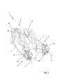
図1は、容器を保持するためのクランプ装置1の側方斜視図を概略的に示している。クランプ装置1は、互いに相対移動可能な2つのクランプアーム2を備え、これらのアームは、各々、それぞれの枢動軸20を中心に回動できるように中央のクランプアームキャリア3上に配置されている。クランプアームキャリア3の作動要素30を作動させることにより、クランプアーム2を、開位置と閉位置との間で枢動させることが可能である。
FIG. 1 schematically shows a side perspective view of a
2つのクランプアーム2の各々が、交換可能なクランプジョー4を有し、クランプジョー4は、保持されるべき容器を保持するためのそれぞれの保持部43を有する。クランプジョー4が、クランプアーム2上に押し込まれ(クランプジョー4が、関連するクランプアーム2の差し込み(プラグオン)領域21に、押し込み方向5に差し込まれることによる)、又は、差し込み領域21が、クランプジョー4に設けられたマウント45内に、押し込み方向5において押し込まれる。
Each of the two
クランプジョー4は、各々、ラッチング要素40を有する。ラッチング要素40は、関連するクランプアーム2に形成された凹部(図2及び図3参照)とのフォームフィットを押し込み方向5において行うためのものである。
Each
図2は、図1のクランプ装置1のさらなる側方斜視図を概略的に示し、この図においてはクランプジョー4がクランプアーム2から取り外されている。これにより、クランプアーム2の各々、及び、差し込み領域21に配置された凹部23を見ることができる。またこれにより、クランプジョー4がクランプアーム2上に押し付けられているときの押し込み方向5における移動を制限するストップ22が見られる。
FIG. 2 schematically shows a further side perspective view of the
図3は、図1及び図2のクランプ装置1のクランプアーム2の断面図を概略的に示している。ラッチング要素40が、クランプジョー4の本体から延在する延在アーム42を含み、延在アーム42は、弾性変形可能な領域41を構成している。ラッチング要素40は、また、相互作用セグメント48も含み、相互作用セグメント48は、延在アーム42を開放方向6(押し込み方向5に垂直な方向)に上昇させるように作動させ得る。この上昇において、ラッチング要素40は凹部23から係合解除され、それによりクランプジョー4はクランプアーム2から取り外される。
FIG. 3 schematically shows a cross-sectional view of the
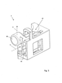
図6を参照してより詳細に説明すると、クランプジョー4のマウント45は以下のように設計される。すなわち、クランプジョー4が差し込み領域21上で、回転を防止されるようガイドされ、且つ、押し込み方向5の方向において本質的に遊びが生じないようにガイドされる。既に述べたように、ストップ22が、クランプジョー4の押し込み移動を制限する。
More specifically with reference to FIG. 6, the
クランプジョー4が差し込み領域21上に押し込まれることを容易にするために、ラッチング要素40は、押し込み方向5に対して逆向きに傾斜した面取り部44を有する。
To facilitate the
図4及び図5は、図1~図3のクランプ装置1の2つのクランプアーム2のクランプジョー4の側方斜視図を示している。クランプジョー4は、クランプ装置の中心軸に対して鏡面対称に設計されて、右側及び左側のクランプジョー4を構成している。
4 and 5 show side perspective views of the
図6は、図5のクランプジョー4を、押し込み方向5における図に対応する側面図で概略的に示している。この図から、マウント45が、押し込み方向5に垂直な方向にマウント45の内壁から延在するクランプ延在部47,47’を備えていることが明らかに分かる。ここで、クランプ延在部47,47’のそれぞれの対は、互いに対向して配置されている。クランプ延在部47はマウントの幅を限定し、一方、クランプ延在部47’は、マウントの高さを限定している。
FIG. 6 schematically shows the
参照符号26が、差し込み領域21の断面の輪郭を示している。断面の輪郭26は、マウント45の幅及び高さよりもそれぞれわずかに大きい幅及び高さを有する。これらはクランプ延在部47,47’により予め画定されている。マウント45の幅及び高さは、ここでは、差し込み領域21の幅及び高さよりも小さく0.98倍である。これは、クランプジョー4がクランプアーム2の差し込み領域21に、予め決められたクランプ力(クランプジョー4及び差し込み領域21の材料の剛性、並びに上述のスケーリングにより存在する高さ及び幅の差に起因する)を与え、従って、クランプジョー4がクランプアーム2上に安定して配置されることを意味する。
クランプジョー4は、ここでは、熱可塑性材料から3Dプリント部品として形成される。
The
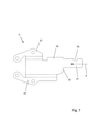
図7は、図1~図3によるクランプ装置1のクランプアーム2を作成するためのブランク24の平面図を概略的に示している。レーザ切断を用いて、ブランク24を、鋼合金製の平坦な金属シートから切り出し、又は切り取る。ここで、差し込み領域21全体が、凹部23及びストップ22と共に、その最終寸法(クランプ装置1に設置された状態のクランプアーム2により示される、所定の許容範囲内の寸法)で既に切り出されている。これは、差し込み領域21へのさらなる処理が、切断されたエッジのバリ取りのためのオプショナルのステップ(例えばサンドブラスト工程)以外には全く必要ないことを意味する。
FIG. 7 schematically shows a plan view of a blank 24 for creating the
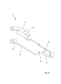
図8に示されているようなクランプアーム2の最終的な形状が、ブランク24に成形プロセスを施すことにより達成され、この場合、このプロセスは、2つの曲げ領域27を、それぞれ曲げ縁25の周りで曲げることにより行われる。
The final shape of the
特に、クランプアーム2が熱可塑性材料から形成されている場合、成形プロセスが熱成形プロセスであることも可能であり、この場合ブランク24は、少なくとも曲げ縁25の領域で加熱され、従って、曲げ領域27に成形プロセスを施すに前に熱変形が可能である。
In particular, if the
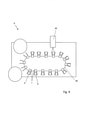
図9は、容器ハンドリング装置8の平面図を概略的に示しており、容器ハンドリング装置8は、容器ハンドリング装置8を介して搬送される容器9をハンドリングするためのハンドリングユニット82を備えている。容器9を、容器ハンドリング装置8を介して搬送するために、容器ハンドリング装置8は、搬送方向84に移動可能なクランプキャリア80を有し、クランプキャリア80上に、図1~図8に記載した実施形態による複数のクランプ装置1が取り付けられている。
FIG. 9 schematically shows a plan view of the
ここでのハンドリングユニット82は、容器9をリンスする(すすぐ)ためのリンスユニットの形態で設計されている。従って、容器ハンドリング装置8は、リンサーを構成している。
The
例示的な実施形態において提示された全ての個々の特徴は、適用可能であれば、本発明の範囲から逸脱せずに互いに組み合わせ、且つ/又は交換し得る。 All individual features presented in the exemplary embodiments may be combined and / or interchanged with each other without departing from the scope of the invention, if applicable.
1 クランプ装置
2 クランプアーム
20 枢動軸
21 差し込み領域
22 ストップ
23 凹部
24 ブランク
25 曲げ縁
26 断面輪郭
27 曲げ領域
3 クランプアームキャリア
30 作動要素
4 クランプジョー
40 ラッチング要素
41 弾性変形可能な領域
42 延在アーム
43 保持部
44 面取り部
45 マウント
46 内壁
47,47’ クランプ延在部
48 相互作用要素
5 押し込み方向
6 開放方向
8 容器ハンドリング装置
80 クランプキャリア
82 ハンドリングユニット
84 搬送方向
9 容器
1 Clamping device
2
8
84
Claims (12)
前記クランプジョー(4)が、関連するクランプアーム(2)に形成された凹部(23)とのフォームフィットを行うためのラッチング要素(40)を有することを特徴とする、クランプ装置(1)。 A clamp device (1) for holding a container (9) in a container handling device (8), preferably for holding a beverage container in a container handling device of a bottling factory, and two movable with respect to each other. Clamping device comprising a clamp arm (2), wherein at least one clamp arm (2) has a replaceable clamp jaw (4) having a holding portion (43) for holding the container (9) to be held. In (1)
The clamp device (1), characterized in that the clamp jaw (4) has a latching element (40) for form fitting with a recess (23) formed in the associated clamp arm (2).
請求項1~請求項9のいずれか一項に記載の少なくとも1つのクランプ装置(1)が前記クランプキャリア(80)に取り付けられていることを特徴とする容器ハンドリング装置(8)。 A container handling device (8) provided with a handling unit (82) for handling the container (9) and also provided with a clamp carrier (80).
A container handling device (8), wherein at least one clamp device (1) according to any one of claims 1 to 9 is attached to the clamp carrier (80).
前記クランプアーム(2)に形成された凹部(23)とのフォームフィットを行うためのラッチング要素(40)を有することを特徴とする、交換可能なクランプジョー(4)。 Replacement of the clamp device (1) for holding the container (9) in the container handling device (8), preferably for the clamp arm (2) of the clamp device (1) for holding the beverage container in the bottling factory. In the clamp jaw (4) which is a possible clamp jaw (4) and includes a holding portion (43) for holding the container (9) to be held.
A replaceable clamp jaw (4) comprising a latching element (40) for form fitting with a recess (23) formed in the clamp arm (2).
Applications Claiming Priority (2)
| Application Number | Priority Date | Filing Date | Title |
|---|---|---|---|
| DE102020113599.8 | 2020-05-20 | ||
| DE102020113599.8A DE102020113599A1 (en) | 2020-05-20 | 2020-05-20 | Clamping device, clamping jaw and container handling device |
Publications (2)
| Publication Number | Publication Date |
|---|---|
| JP2022008096A true JP2022008096A (en) | 2022-01-13 |
| JP7788226B2 JP7788226B2 (en) | 2025-12-18 |
Family
ID=76034529
Family Applications (1)
| Application Number | Title | Priority Date | Filing Date |
|---|---|---|---|
| JP2021084608A Active JP7788226B2 (en) | 2020-05-20 | 2021-05-19 | Clamping device, clamp jaw and container handling device |
Country Status (5)
| Country | Link |
|---|---|
| US (1) | US11806863B2 (en) |
| EP (1) | EP3912938B1 (en) |
| JP (1) | JP7788226B2 (en) |
| CN (1) | CN113697474A (en) |
| DE (1) | DE102020113599A1 (en) |
Families Citing this family (2)
| Publication number | Priority date | Publication date | Assignee | Title |
|---|---|---|---|---|
| BE1030740B1 (en) | 2022-07-28 | 2024-02-26 | Aseptic Tech Sa | Container handling system and handling method |
| DE102023105126A1 (en) * | 2023-03-01 | 2024-09-05 | Krones Aktiengesellschaft | Holding jaw and clamp device for holding a container |
Citations (6)
| Publication number | Priority date | Publication date | Assignee | Title |
|---|---|---|---|---|
| JPS62287893A (en) * | 1986-05-26 | 1987-12-14 | 東京コカコーラボトリング株式会社 | Bottle-inside washer |
| JPH01317989A (en) * | 1988-06-17 | 1989-12-22 | Murata Kogyo Kk | Transport apparatus |
| JPH04505426A (en) * | 1989-12-29 | 1992-09-24 | 株式会社アマダ | Manipulator for manipulating metal plate materials |
| US20170066139A1 (en) * | 2015-09-09 | 2017-03-09 | Carbon Robotics, Inc. | Reconfigurable robotic system and methods |
| JP2017054840A (en) * | 2015-09-07 | 2017-03-16 | パナソニックIpマネジメント株式会社 | Component mounting device |
| JP2019150944A (en) * | 2017-12-11 | 2019-09-12 | クロネス アーゲー | Active gripping device |
Family Cites Families (23)
| Publication number | Priority date | Publication date | Assignee | Title |
|---|---|---|---|---|
| DE226826C (en) | ||||
| US4676541A (en) * | 1982-11-27 | 1987-06-30 | Cleveland-Guest (Engineering) Limited | Robot hand |
| DD226826A1 (en) | 1984-09-07 | 1985-09-04 | Smab Forsch Entw Rat | REPLACEABLE GRIPPER FINGERS |
| US4621409A (en) * | 1985-03-06 | 1986-11-11 | Westinghouse Electric Corp. | Harness formation finger interchange |
| DE3602839A1 (en) * | 1986-01-30 | 1987-08-06 | Fraunhofer Ges Forschung | RECORDING DEVICE |
| US4961492A (en) * | 1988-07-22 | 1990-10-09 | Simplimatic Engineering Company | Article carrying conveyor and wearstrip set therefor |
| DE9003313U1 (en) * | 1990-03-21 | 1990-05-23 | Fritz Schäfer GmbH, 5908 Neunkirchen | Fastening and/or holding device for roller strips on support rails or similar, in particular of flow racks |
| ITRM20020147A1 (en) * | 2002-03-18 | 2003-09-18 | Sipa Spa | CLAMP GRIPPING DEVICE FOR BOTTLES AND SIMILAR. |
| US7328925B1 (en) * | 2003-04-04 | 2008-02-12 | Bouncing Brain Innovations Season Two Subsidiary 17, Llc | Gripper for plastic bag handles |
| DE20305988U1 (en) | 2003-04-14 | 2003-07-03 | Tyrolon-Schulnig Ges.M.B.H., Hochfilzen | transport star |
| FR2903927B1 (en) * | 2006-07-21 | 2008-09-05 | Sidel Participations | RAPID ASSEMBLY DEVICE FOR SUPPORTING TOOLS. |
| DE102007048861A1 (en) | 2007-10-11 | 2009-04-16 | Robert Bosch Gmbh | Cleaning device for e.g. syringe, has gripping units fastened with conveyor belt and engaging container, where each gripping unit comprises gripping elements and container engages between elements |
| DE102009003595A1 (en) * | 2009-03-10 | 2010-09-16 | Bucyrus Europe Gmbh | Scratch for chain scraper conveyor |
| IT1394320B1 (en) | 2009-05-07 | 2012-06-06 | Mbf Spa | MACHINE TO TREAT CONTAINERS, IN PARTICULAR IN A BOTTLING SYSTEM FOR FOOD PRODUCTS |
| JP5892765B2 (en) | 2011-10-24 | 2016-03-23 | 川崎重工業株式会社 | Replacement claw module for robot hand |
| DE102014101959A1 (en) * | 2014-02-17 | 2015-08-20 | Khs Gmbh | Tool-free protective body for protecting glass bottles in star pockets |
| DE102016004087A1 (en) * | 2016-02-15 | 2017-08-17 | Kastanienbaum GmbH | Effector unit for a robot, working device with a robot and method for changing an effector in robots |
| TWM539498U (en) * | 2016-11-10 | 2017-04-11 | guo-rong Luo | Delivery system for organized wax blocks |
| JP6551805B2 (en) * | 2017-03-06 | 2019-07-31 | パナソニックIpマネジメント株式会社 | Component mounting apparatus and component mounting method |
| DE102017105024B4 (en) | 2017-03-09 | 2021-02-11 | Tyrolon-Schulnig Gmbh | Rinser system |
| IT201800000708A1 (en) * | 2018-01-11 | 2019-07-11 | Pe Labellers Spa | CONTAINER TRANSPORT STAR. |
| CN110406886B (en) * | 2019-08-16 | 2024-05-31 | 上海牧森自动化设备有限公司 | Conveying side plate assembly |
| CN110802624B (en) * | 2019-11-22 | 2020-11-13 | 合肥常青机械股份有限公司 | Gripper-replaceable robot arm |
-
2020
- 2020-05-20 DE DE102020113599.8A patent/DE102020113599A1/en active Pending
-
2021
- 2021-05-19 CN CN202110546532.5A patent/CN113697474A/en active Pending
- 2021-05-19 US US17/324,391 patent/US11806863B2/en active Active
- 2021-05-19 JP JP2021084608A patent/JP7788226B2/en active Active
- 2021-05-20 EP EP21174987.4A patent/EP3912938B1/en active Active
Patent Citations (6)
| Publication number | Priority date | Publication date | Assignee | Title |
|---|---|---|---|---|
| JPS62287893A (en) * | 1986-05-26 | 1987-12-14 | 東京コカコーラボトリング株式会社 | Bottle-inside washer |
| JPH01317989A (en) * | 1988-06-17 | 1989-12-22 | Murata Kogyo Kk | Transport apparatus |
| JPH04505426A (en) * | 1989-12-29 | 1992-09-24 | 株式会社アマダ | Manipulator for manipulating metal plate materials |
| JP2017054840A (en) * | 2015-09-07 | 2017-03-16 | パナソニックIpマネジメント株式会社 | Component mounting device |
| US20170066139A1 (en) * | 2015-09-09 | 2017-03-09 | Carbon Robotics, Inc. | Reconfigurable robotic system and methods |
| JP2019150944A (en) * | 2017-12-11 | 2019-09-12 | クロネス アーゲー | Active gripping device |
Also Published As
| Publication number | Publication date |
|---|---|
| CN113697474A (en) | 2021-11-26 |
| JP7788226B2 (en) | 2025-12-18 |
| US20210362350A1 (en) | 2021-11-25 |
| EP3912938C0 (en) | 2025-07-30 |
| DE102020113599A1 (en) | 2021-11-25 |
| EP3912938A1 (en) | 2021-11-24 |
| US11806863B2 (en) | 2023-11-07 |
| EP3912938B1 (en) | 2025-07-30 |
Similar Documents
| Publication | Publication Date | Title |
|---|---|---|
| JP2022008096A (en) | Clamp device, clamp jaw and container-handling apparatus | |
| US10661451B2 (en) | Clamp gripping device and system consisting of such devices | |
| EP3678839B1 (en) | Facility for transporting preforms equipped with a device for angularly indexing spindles | |
| CN104540755B (en) | Container gripper and conveying element with the container gripper | |
| KR101991472B1 (en) | Method and system for the manufacture of a razor cartridge | |
| JP2018507791A (en) | Clamping system that can be automated | |
| KR102102860B1 (en) | Automatic Clamping Device for Cutting Steel for Automotive Split Mold | |
| US7748522B2 (en) | Conveyor device | |
| CN104736294A (en) | joint structure | |
| US10994940B1 (en) | Apparatus for guiding containers for a conveyor | |
| RU2362645C2 (en) | Method for shaping of metal container surface | |
| JP6088196B2 (en) | Gripper | |
| US7775381B2 (en) | Device for supporting bottles | |
| RU2384515C2 (en) | Manipulator for manipulating automotive wheel disk in surface treatment plant | |
| EP1950025A1 (en) | Plastic container with in-mould label | |
| JP2015155200A (en) | Blow molding machine with centering of blow mold base | |
| JP6046247B2 (en) | Forming device for container with handle, conveying jig and handle for container | |
| KR20220049162A (en) | Valve opening/closing seat polishing automation device and polishing method | |
| JP2008535673A (en) | Clamp collet | |
| CN111301924B (en) | Wine lifter | |
| JP6554784B2 (en) | Robot hand, robot and robot system | |
| CN114585575A (en) | Replacing system for a container element turnover device | |
| KR20070089842A (en) | Devices for selectively and progressively fixing metal containers | |
| FR3031918A1 (en) | TOOL FOR CLEANING CUTTING GRIDS | |
| JP7122992B2 (en) | jig |
Legal Events
| Date | Code | Title | Description |
|---|---|---|---|
| A621 | Written request for application examination |
Free format text: JAPANESE INTERMEDIATE CODE: A621 Effective date: 20240327 |
|
| A977 | Report on retrieval |
Free format text: JAPANESE INTERMEDIATE CODE: A971007 Effective date: 20250428 |
|
| A131 | Notification of reasons for refusal |
Free format text: JAPANESE INTERMEDIATE CODE: A131 Effective date: 20250507 |
|
| A521 | Request for written amendment filed |
Free format text: JAPANESE INTERMEDIATE CODE: A523 Effective date: 20250731 |
|
| A131 | Notification of reasons for refusal |
Free format text: JAPANESE INTERMEDIATE CODE: A131 Effective date: 20250826 |
|
| A521 | Request for written amendment filed |
Free format text: JAPANESE INTERMEDIATE CODE: A523 Effective date: 20251107 |
|
| TRDD | Decision of grant or rejection written | ||
| A01 | Written decision to grant a patent or to grant a registration (utility model) |
Free format text: JAPANESE INTERMEDIATE CODE: A01 Effective date: 20251118 |
|
| A61 | First payment of annual fees (during grant procedure) |
Free format text: JAPANESE INTERMEDIATE CODE: A61 Effective date: 20251208 |
|
| R150 | Certificate of patent or registration of utility model |
Ref document number: 7788226 Country of ref document: JP Free format text: JAPANESE INTERMEDIATE CODE: R150 |