JP2022008099A - Rotation axis center position measuring method of machine tool - Google Patents
Rotation axis center position measuring method of machine tool Download PDFInfo
- Publication number
- JP2022008099A JP2022008099A JP2021085332A JP2021085332A JP2022008099A JP 2022008099 A JP2022008099 A JP 2022008099A JP 2021085332 A JP2021085332 A JP 2021085332A JP 2021085332 A JP2021085332 A JP 2021085332A JP 2022008099 A JP2022008099 A JP 2022008099A
- Authority
- JP
- Japan
- Prior art keywords
- tool
- axis
- center position
- machine tool
- measuring
- Prior art date
- Legal status (The legal status is an assumption and is not a legal conclusion. Google has not performed a legal analysis and makes no representation as to the accuracy of the status listed.)
- Granted
Links
Images










Landscapes
- Length Measuring Devices By Optical Means (AREA)
- Machine Tool Sensing Apparatuses (AREA)
Abstract
Description
本発明は、工作機械の回転軸中心位置計測方法に関する。 The present invention relates to a method for measuring the center position of a rotating shaft of a machine tool.
工作機械においては、主軸に装着された工具により、テーブルに載置されたワークを加工する。加工時には、工具とワークとをX軸,Y軸,Z軸の各方向へ三次元移動させることで、ワークに任意の立体形状が加工できる。
工作機械のうち一部は、加工自由度を高めるために、XYZ方向の並進軸に加えて、並進軸回りに工具を回転させる回転軸を備えている。追加される回転軸としては、例えばX軸回りの回転であるA軸、Y軸回りの回転であるB軸、Z軸回りの回転であるC軸などがある。このような多軸制御工作機械としては、例えば、X軸,Y軸,Z軸の3つにA軸,C軸の2つを追加した5軸制御の工作機械が利用されている。
In a machine tool, a work placed on a table is machined by a tool mounted on a spindle. At the time of machining, an arbitrary three-dimensional shape can be machined on the work by three-dimensionally moving the tool and the work in each of the X-axis, Y-axis, and Z-axis directions.
Some machine tools are provided with a rotation axis that rotates the tool around the translation axis in addition to the translation axis in the XYZ direction in order to increase the degree of freedom in machining. Examples of the rotation axis to be added include an A axis that is a rotation around the X axis, a B axis that is a rotation around the Y axis, and a C axis that is a rotation around the Z axis. As such a multi-axis control machine tool, for example, a 5-axis control machine tool in which two axes, A-axis and C-axis, are added to three of X-axis, Y-axis, and Z-axis is used.
前述した多軸制御工作機械においては、加工精度の向上のために、並進軸の位置誤差を最小限とするとともに、回転軸の角度誤差および回転中心の位置精度を最小限とすることが必要である。このうち、回転軸中心位置の誤差による加工精度の低下を抑止するために、回転軸の中心位置を計測しておき、加工時にパラメータとして補正制御を行うことがなされている(特許文献1参照)。 In the above-mentioned multi-axis control machine tool, in order to improve the machining accuracy, it is necessary to minimize the position error of the translation axis and to minimize the angle error of the rotation axis and the position accuracy of the center of rotation. be. Of these, in order to suppress a decrease in machining accuracy due to an error in the center position of the rotating shaft, the center position of the rotating shaft is measured and correction control is performed as a parameter during machining (see Patent Document 1). ..
特許文献1では、回転軸の中心位置を計測する方法として、ワークに代えて基準マスタとなるターゲット球をテーブル上に固定するとともに、工具に代えてタッチプローブを主軸に装着しておき、計測すべき回転軸を複数の角度に割り出し、各角度位置でタッチプローブをターゲット球に接触させてターゲット球の中心位置を計測し、複数の角度位置での計測値から当該回転軸の中心位置を算出している。
とくに、特許文献1では、並進軸の動作範囲が構造的に制限される工作機械の場合でも回転軸の中心位置が高精度に計測できるように、回転軸の複数の角度位置でのタッチプローブとターゲット球との接触動作を、並進軸の動作可能範囲内だけで行い、移動が制限される範囲では接触動作を行うことなく、計算により回転軸中心位置を計測している。
In
In particular, in
一方、測定対象の工具と測定装置が干渉して旋回軸(第4軸,第5軸)の割出範囲が大きく制限される場合でも、1個の測定装置だけでX,Y,Z方向すべての誤差量を測定することができる刃先位置検出方法が開発されている(特許文献2)。
特許文献2では、旋回テーブルの回転軸上にある工具の最下点と、旋回テーブルの回転軸と直交する面内にある工具外周の2箇所以上とを測定して求まる工具中心点の2方向の誤差量より、X,Y,Z方向の刃先位置決め誤差量を求めている。
On the other hand, even if the tool to be measured and the measuring device interfere with each other and the indexing range of the swivel axis (4th axis, 5th axis) is greatly limited, only one measuring device is used in all the X, Y, and Z directions. A cutting edge position detection method capable of measuring the amount of error in the above has been developed (Patent Document 2).
In
前述した特許文献1の計測方法により、並進軸の動作範囲が制限されている工作機械の場合でも、回転軸の中心位置を高精度に計測できるようになった。
しかし、特許文献1の計測方法では、ターゲット球の位置を検出するために、刃物に代えてタッチプローブを主軸に装着する。
このため、計測時の工作機械は、主軸に工具が装着された実際の加工時の状態ではなく、計測した回転軸の中心位置は加工時の中心位置とは異なり、計測精度に限界があるという問題があった。
さらに、主軸にタッチプローブが装着できない工作機械では、そもそも特許文献1の計測方法を利用できないという問題があった。
一方、特許文献2では、工具中心点の2方向の誤差量を求めるために、幾つかの方法が提示されているが、工具種類がボールエンドミルに限定され、工具先端を「真円」として扱うことが前提となっており、異なる先端形状の工具には適用ができず、中心位置の高精度な計測は困難であった。このため、多様な先端形状の工具に対しても、単純な計算で回転軸の中心位置を高精度に計測できるようにすることが求められていた。
According to the measurement method of
However, in the measurement method of
For this reason, the machine tool at the time of measurement is not in the state at the time of actual machining with the tool attached to the spindle, and the center position of the measured rotation shaft is different from the center position at the time of machining, and the measurement accuracy is limited. There was a problem.
Further, there is a problem that the measurement method of
On the other hand, in
本発明の目的は、タッチプローブを用いずに単純な計算で回転軸の中心位置を高精度に計測できる工作機械の回転軸中心位置計測方法を提供することにある。
本発明の他の目的は、多様な先端形状の工具に対しても、単純な計算で回転軸の中心位置を高精度に計測できる工作機械の回転軸中心位置計測方法を提供することにある。
An object of the present invention is to provide a method for measuring the center position of a rotating shaft of a machine tool, which can measure the center position of the rotating shaft with high accuracy by a simple calculation without using a touch probe.
Another object of the present invention is to provide a method for measuring the center position of a rotating shaft of a machine tool, which can measure the center position of the rotating shaft with high accuracy by a simple calculation even for a tool having various tip shapes.
本発明の工作機械の回転軸中心位置計測方法は、主軸に工具を装着し、前記工具の位置を非接触で検出可能な検出ユニットをテーブルに設置しておき、計測対象の回転軸について前記工具と前記テーブルとを所定の角度位置に割り出し、各角度位置で前記検出ユニットを用いて前記テーブルに対する前記工具の位置を検出する検出動作を繰り返し、複数回の前記検出動作で検出された各角度位置での前記工具の位置から前記回転軸の中心位置を計算することを特徴とする。 In the method for measuring the center position of a rotary shaft of a machine tool of the present invention, a tool is mounted on a spindle, a detection unit capable of detecting the position of the tool in a non-contact manner is installed on a table, and the rotary shaft to be measured is the tool. And the table are indexed to a predetermined angle position, the detection operation of detecting the position of the tool with respect to the table is repeated at each angle position using the detection unit, and each angle position detected by the detection operation a plurality of times. It is characterized in that the center position of the rotating shaft is calculated from the position of the tool in.
このような本発明では、非接触式の検出ユニットを用いた検出動作を複数回繰り返し、各角度位置での工具の位置から幾何学的な計算を行うことで、回転軸の中心位置を高精度に計測することができる。
計測にあたって、工作機械の主軸には加工用の工具を装着でき、計測の直前に主軸を回転させて昇温させ、加工時と同様な状態で計測することができる。また、主軸にタッチプローブが装着できない工作機械にも、幅広く適用できる。
従って、本発明によれば、タッチプローブを用いずに単純な計算で回転軸の中心位置を高精度に計測できる工作機械の回転軸中心位置計測方法を提供することができる。
In the present invention as described above, the detection operation using the non-contact type detection unit is repeated a plurality of times, and the geometric calculation is performed from the position of the tool at each angle position to obtain the center position of the rotation axis with high accuracy. Can be measured.
In the measurement, a tool for machining can be attached to the spindle of the machine tool, and the spindle can be rotated to raise the temperature immediately before the measurement, and the measurement can be performed in the same state as during machining. It can also be widely applied to machine tools where the touch probe cannot be attached to the spindle.
Therefore, according to the present invention, it is possible to provide a method for measuring the center position of the rotation axis of a machine tool, which can measure the center position of the rotation axis with high accuracy by a simple calculation without using a touch probe.
なお、本発明では、テーブルに対する検出ユニットの位置および向きが高精度に把握できていれば、より少ない回数で回転軸の回転中心を計算できるが、テーブルに対する検出ユニットの位置および向きが高精度に把握できていなくても、複数回の検出動作により各角度位置での工具の位置を検出することで、幾何学的演算により工具の先端位置を絞り込んで高精度に確定することができる。 In the present invention, if the position and orientation of the detection unit with respect to the table can be grasped with high accuracy, the rotation center of the rotation axis can be calculated with a smaller number of times, but the position and orientation of the detection unit with respect to the table can be calculated with high accuracy. Even if it cannot be grasped, by detecting the position of the tool at each angle position by a plurality of detection operations, it is possible to narrow down the tip position of the tool by geometric calculation and determine it with high accuracy.
本発明の工作機械の回転軸中心位置計測方法において、前記検出ユニットは、前記工具の先端が前記検出ユニットにおける特定位置にあることを非接触で検出可能であり、前記検出動作では、前記主軸と前記テーブルとを相対移動させて前記工具と前記テーブルとを所定の角度位置に割り出し、前記各角度位置で前記工具が前記検出ユニットの前記特定位置にくるように前記主軸と前記テーブルとの相対位置を調節し、この状態で前記主軸と前記テーブルとの相対位置から前記各角度位置での前記テーブルに対する前記工具の位置を検出することが好ましい。 In the method for measuring the center position of a rotary axis of a machine tool of the present invention, the detection unit can detect that the tip of the tool is at a specific position in the detection unit in a non-contact manner, and in the detection operation, the detection unit and the spindle The table is moved relative to each other to index the tool and the table into predetermined angular positions, and the relative positions of the spindle and the table so that the tool comes to the specific position of the detection unit at each angle position. In this state, it is preferable to detect the position of the tool with respect to the table at each angle position from the relative position between the spindle and the table.
本発明において、検出動作として検出ユニットを用いてテーブルに対する工具の位置を検出する際には、検出ユニットにおいて工具の位置を検出してもよく、検出ユニットを工具の位置決め治具として用い、工作機械の制御装置から制御用の位置データを取得してもよい。すなわち、工作機械を制御装置の制御下で動作させ、主軸を移動させて工具を検出ユニットの特定位置に配置し、この状態で工作機械の制御装置における主軸の位置データを参照することで、工具の位置を取得することができる。特定位置としては、検出ユニットにおける工具検出領域の中心位置などが利用できる。 In the present invention, when the detection unit is used as a detection operation to detect the position of the tool with respect to the table, the position of the tool may be detected by the detection unit, and the detection unit is used as a tool positioning jig to be used as a machine tool. The position data for control may be acquired from the control device of. That is, by operating the machine tool under the control of the control device, moving the spindle to place the tool at a specific position of the detection unit, and referring to the position data of the spindle in the control device of the machine tool in this state, the tool You can get the position of. As the specific position, the center position of the tool detection area in the detection unit can be used.
本発明の工作機械の回転軸中心位置計測方法において、前記工具の前記テーブルの径方向の位置を検出可能な前記検出ユニットを用い、前記工具と前記テーブルとを、前記回転軸を挟んで第1方向に対向する2つの角度位置、および前記回転軸を挟んで前記第1方向と交差する第2方向に対向する2つの角度位置の4つの角度位置に割り出し、各角度位置で前記検出動作を行って前記工具の前記テーブルの径方向の位置を検出し、前記第1方向に対向する2つの角度位置で検出された前記工具の位置を結ぶ線分の中点を通りかつ前記第1方向に交差する第1直線と、前記第2方向に対向する2つの角度位置で検出された前記工具の位置を結ぶ線分の中点を通りかつ前記第2方向に交差する第2直線とを計算し、前記第1直線と前記第2直線との交点を前記回転軸の中心位置として計測してもよい。 In the method for measuring the center position of the rotary axis of the machine tool of the present invention, the detection unit capable of detecting the radial position of the table of the tool is used, and the tool and the table are first sandwiched between the rotary shaft. The detection operation is performed at each of the two angular positions facing the directions and the two angular positions facing the second direction intersecting the first direction with the rotation axis in between. Detects the radial position of the table of the tool, passes through the midpoint of the line segment connecting the positions of the tools detected at the two angular positions facing the first direction, and intersects in the first direction. The first straight line to be used and the second straight line passing through the midpoint of the line segment connecting the positions of the tools detected at the two angular positions facing the second direction and intersecting the second direction are calculated. The intersection of the first straight line and the second straight line may be measured as the center position of the rotation axis.
本発明において、テーブルの径方向の工具の位置を検出可能な検出ユニットとしては、
工具の側面からの画像を検出して画像上の工具の位置を検出する画像センサを、テーブルの周方向に向けて設置したものが利用できる。
回転軸を挟んで対向する4つの角度位置としては、例えばテーブルの0度位置と180度位置を第1方向に対向する2つの角度位置とし、90度位置および270度位置を第2方向に対向する2つの角度位置とすることができる。
このような本発明によれば、0度と180度の角度位置での検出動作では確定できない中心位置の推定範囲を、90度と270度の角度位置での検出動作による工具の位置により絞り込み、正確な回転軸の中心を確定することができ、計4つの角度位置での検出動作で、回転軸の中心位置を高精度に計測できる。
In the present invention, as a detection unit capable of detecting the position of the tool in the radial direction of the table,
An image sensor that detects an image from the side surface of the tool and detects the position of the tool on the image can be installed so as to face the circumferential direction of the table.
As the four angle positions facing each other across the axis of rotation, for example, the 0 degree position and the 180 degree position of the table are set as two angle positions facing each other in the first direction, and the 90 degree position and the 270 degree position face each other in the second direction. It can be two angular positions.
According to the present invention, the estimated range of the center position, which cannot be determined by the detection operation at the angle positions of 0 and 180 degrees, is narrowed down by the position of the tool by the detection operation at the angle positions of 90 degrees and 270 degrees. The center of the rotation axis can be determined accurately, and the center position of the rotation axis can be measured with high accuracy by the detection operation at a total of four angle positions.
本発明の工作機械の回転軸中心位置計測方法において、前記工具の前記テーブルの表面に沿った位置を検出可能な前記検出ユニットを用い、前記工具と前記テーブルとを、前記回転軸を挟んで対向する2つの角度位置に割り出し、各角度位置で前記検出動作を行って前記工具の前記テーブルの表面に沿った位置を検出し、2回の前記検出動作での前記工具の位置を結ぶ線分の中点を計算し、前記中点を前記回転軸の中心位置として計測してもよい。 In the method for measuring the center position of the rotation axis of a machine tool of the present invention, the detection unit capable of detecting the position of the tool along the surface of the table is used, and the tool and the table face each other with the rotation axis interposed therebetween. A line segment connecting the positions of the tool in the two detection operations to detect the position of the tool along the surface of the table of the tool by performing the detection operation at each angle position. The midpoint may be calculated and measured with the midpoint as the center position of the rotation axis.
本発明において、テーブルの表面に沿った工具の位置を検出可能な検出ユニットとしては、工具のテーブルの径方向の位置および周方向の位置を検出可能な検出ユニットが利用でき、より具体的には、オートフォーカス機能を有する画像センサシステムをテーブルの周方向に向けてテーブルに設置し、工具の側面からの画像上の工具の位置を径方向の位置とし、オートフォーカス機能で検出される画像の奥行き方向の工具の位置を周方向の位置として検出することができる。
回転軸を挟んで対向する2つの角度位置としては、例えばテーブルの0度位置と180度位置などとすることができる。
このような本発明によれば、2つの角度位置での検出動作という簡単な操作で、回転軸の中心位置を高精度に計測できる。
In the present invention, as a detection unit capable of detecting the position of the tool along the surface of the table, a detection unit capable of detecting the radial position and the circumferential position of the table of the tool can be used, and more specifically, the detection unit can be used. , An image sensor system with an autofocus function is installed on the table facing the circumferential direction of the table, the position of the tool on the image from the side of the tool is the radial position, and the depth of the image detected by the autofocus function. The position of the tool in the direction can be detected as the position in the circumferential direction.
The two angular positions facing each other across the rotation axis can be, for example, a 0 degree position and a 180 degree position of the table.
According to the present invention as described above, the center position of the rotating shaft can be measured with high accuracy by a simple operation of detection operation at two angular positions.
本発明の工作機械の回転軸中心位置計測方法において、前記工具の前記テーブルの径方向の位置を検出可能な前記検出ユニットを用い、前記工具と前記テーブルとを、前記回転軸を中心とした所定角度範囲内の複数の角度位置に割り出し、各角度位置で前記検出動作を行って前記工具の前記テーブルの径方向の位置を検出し、複数回の前記検出動作で得られた前記工具の位置をプロットし、近似計算により前記回転軸の中心位置を計算してもよい。 In the method for measuring the center position of the rotation axis of a machine tool of the present invention, the detection unit capable of detecting the radial position of the table of the tool is used, and the tool and the table are designated with the rotation axis as the center. The position of the tool obtained by performing the detection operation at each angle position is detected at a plurality of angular positions within the angle range, the radial position of the table of the tool is detected, and the position of the tool obtained by the detection operation is performed a plurality of times. You may plot and calculate the center position of the rotation axis by approximate calculation.
このような本発明では、工作機械の構造的な制約で、回転軸まわりの一部の角度範囲での検出動作ができない場合でも、同角度範囲を除く限定された角度範囲で複数回の検出動作を繰り返すことで、回転軸中心位置の候補位置を例えば円弧状にプロットすることができ、最小二乗法などの近似計算により中心位置を確定することができる。 In the present invention as described above, even if the detection operation cannot be performed in a part of the angle range around the rotation axis due to the structural restrictions of the machine tool, the detection operation is performed a plurality of times in a limited angle range excluding the same angle range. By repeating, the candidate position of the center position of the rotation axis can be plotted in an arc shape, for example, and the center position can be determined by an approximate calculation such as the least squares method.
本発明の工作機械の回転軸中心位置計測方法において、前記検出ユニットは、前記テーブルに対する固定手段を有することが好ましい。
本発明において、テーブルに設置される検出ユニットは、各角度位置での検出動作の間に、テーブルに対する設置位置が変動しないことが必要である。テーブルが上向きの場合、単に載置つまりテーブル表面に対して摩擦力で移動規制されるものであればよい。テーブルが上向き以外になる場合、検出ユニットがテーブルから落下しないように、テーブルに対して他の固定手段を用いることが好ましい。
固定手段としては、着脱が容易なものが好ましく、例えばマグネットによる吸着、粘着シートや接着剤などによる粘着、クランプなどの機械的な固定であってもよい。検出ユニットは非接触式であるため、工具との接触による移動は基本的になく、検出ユニットをテーブルに対して強固に固定する必要はない。
In the method for measuring the center position of a rotating shaft of a machine tool of the present invention, it is preferable that the detection unit has a fixing means to the table.
In the present invention, it is necessary that the detection unit installed on the table does not change its installation position with respect to the table during the detection operation at each angle position. When the table is facing upward, it is sufficient that the table is simply placed, that is, the movement is restricted by frictional force with respect to the table surface. If the table is not facing up, it is preferable to use other fixing means to the table to prevent the detection unit from falling off the table.
As the fixing means, those that are easily attached and detached are preferable, and for example, adsorption by a magnet, adhesion by an adhesive sheet or an adhesive, or mechanical fixing such as a clamp may be used. Since the detection unit is non-contact type, there is basically no movement due to contact with the tool, and it is not necessary to firmly fix the detection unit to the table.
本発明の工作機械の回転軸中心位置計測方法において、前記検出ユニットは、平行光束を照射する照明部と、前記平行光束を検出する撮像部と、を有し、前記撮像部で検出された画像から前記平行光束中に配置された前記工具の先端位置を検出することが好ましい。 In the method for measuring the center position of the rotation axis of a machine tool of the present invention, the detection unit includes an illumination unit that irradiates a parallel light flux and an image pickup unit that detects the parallel light flux, and the image detected by the image pickup unit. It is preferable to detect the tip position of the tool arranged in the parallel luminous flux.
本発明において、照射部としては、点光源とテレセントリックレンズを用いて平行光束を形成するもの、直線状に配列された光源により平行光束を形成するもの、光ビームを平行に振って擬似的に平行光束を形成するもの、などが適宜利用できる。
本発明において、撮像部としては、例えばCCD(Charge Coupled Device)式のカメラなど、撮影した画像をデータ出力して画像処理可能な画像検出器を用いることが好ましい。
本発明において、撮像部で検出された画像から平行光束中に配置された工具の先端位置を検出する際には、撮像部で検出された画像に対して既存の画像処理を行うことにより、平行光束中に配置された工具の影を検出し、エッジ検出により工具先端の輪郭からその中心位置を演算することで工具の先端位置を計算するソフトウェアを用いることができる。
このような本発明では、光学式の検出を行うことで、工具の先端位置を非接触で高精度に検出することができる。
また、位置検出にあたっては、照明部と撮像部との間の平行光束の中に工具の先端を配置するだけでよく、検出操作が容易である。
In the present invention, as the irradiation unit, a light beam is formed by using a point light source and a telecentric lens, a parallel light flux is formed by a linearly arranged light source, and a light beam is shaken in parallel to be pseudo-parallel. Those that form a light source can be used as appropriate.
In the present invention, it is preferable to use an image detector capable of outputting data and processing the captured image, such as a CCD (Charge Coupled Device) type camera, as the image pickup unit.
In the present invention, when the tip position of the tool arranged in the parallel light beam is detected from the image detected by the image pickup unit, the existing image processing is performed on the image detected by the image pickup unit to perform parallel processing. It is possible to use software that calculates the tip position of the tool by detecting the shadow of the tool placed in the light beam and calculating the center position from the contour of the tip of the tool by edge detection.
In the present invention as described above, the position of the tip of the tool can be detected with high accuracy without contact by performing optical detection.
Further, in the position detection, it is only necessary to arrange the tip of the tool in the parallel light flux between the illumination unit and the image pickup unit, and the detection operation is easy.
本発明の工作機械の回転軸中心位置計測方法において、前記工具を前記撮像部に対して回転した状態で、前記撮像部で前記画像を検出し、前記画像から前記工具の輪郭を検出し、前記輪郭の対称性から前記工具の中心軸線を検出し、前記中心軸線と前記輪郭との交点を前記工具の先端位置として検出することが好ましい。
このような本発明では、回転する工具の輪郭が線対称になることを利用して、工具の中心軸線を検出できるとともに、検出した中心軸線と工具の輪郭との交点をとることで、工具の先端位置を確定することができる。この際、工具の先端形状について制約はなく、多様な先端形状の工具に対して先端位置を確定できる。さらに、先端位置の確定は、工具の画像上の幾何学的演算処理だけでよく、単純な計算で工具の先端位置ないし回転軸の中心位置を高精度に計測できる。
In the method for measuring the center position of the rotation axis of a machine tool of the present invention, the image is detected by the image pickup unit in a state where the tool is rotated with respect to the image pickup unit, the contour of the tool is detected from the image, and the tool is detected. It is preferable to detect the central axis of the tool from the symmetry of the contour and detect the intersection of the central axis and the contour as the tip position of the tool.
In the present invention as described above, the central axis of the tool can be detected by utilizing the fact that the contour of the rotating tool becomes axisymmetric, and the intersection of the detected central axis and the contour of the tool is taken to obtain the tool of the tool. The tip position can be determined. At this time, there are no restrictions on the tip shape of the tool, and the tip position can be determined for tools having various tip shapes. Further, the tip position can be determined only by the geometric calculation process on the image of the tool, and the tip position of the tool or the center position of the rotation axis can be measured with high accuracy by a simple calculation.
本発明の工作機械の回転軸中心位置計測方法において、前記中心軸線と前記輪郭との交点を前記工具の先端位置として検出する際に、前記中心軸線の両側に所定距離をおいて一対の平行線を設定し、一対の前記平行線と前記輪郭との交点を通りかつ前記中心軸線と直交する補助輪郭線を設定し、前記中心軸線と前記補助輪郭線との交点を前記工具の先端位置として検出することが好ましい。
このような本発明では、例えば、先端に複数の突起をもつ工具や、偏った先端をもつ工具など、回転した状態では先端部の輪郭の形状が不明瞭になる工具についても、補助輪郭線を設定することで、中心から工具の先端位置を確定できる。これにより、多様な先端形状の工具に対しても、単純な計算で工具の先端位置ないし回転軸の中心位置を高精度に計測できる。
In the method for measuring the center position of the rotation axis of the machine tool of the present invention, when the intersection of the center axis and the contour is detected as the tip position of the tool, a pair of parallel lines are separated from each other on both sides of the center axis. Is set, an auxiliary contour line that passes through the intersection of the pair of parallel lines and the contour and is orthogonal to the central axis is set, and the intersection of the central axis and the auxiliary contour is detected as the tip position of the tool. It is preferable to do so.
In the present invention as described above, the auxiliary contour line is also provided for a tool having a plurality of protrusions at the tip, a tool having a biased tip, and the like, in which the shape of the contour of the tip becomes unclear in a rotated state. By setting, the tip position of the tool can be determined from the center. As a result, even for tools with various tip shapes, the tip position of the tool or the center position of the rotation axis can be measured with high accuracy by simple calculation.
本発明の工作機械の回転軸中心位置計測方法において、前記工具の延伸方向に前記輪郭を横断する複数の横断線を設定し、各々の前記横断線について前記輪郭との2つの交点および2つの前記交点の中点を検出し、各々の前記横断線の前記中点を通る直線を前記工具の中心軸線とすることができる。
このような本発明では、工具の延伸方向(工具の向き、概略的な軸線方向)を利用して、工具の正確な中心軸線(回転対称軸)を検出することができる。この際、複数の横断線を用いる幾何学的な演算処理により、簡単に工具の先端位置ないし回転軸の中心位置を高精度に計測できる。
In the method for measuring the center position of the rotation axis of the machine tool of the present invention, a plurality of transversals crossing the contour are set in the extending direction of the tool, and for each of the transversals, two intersections with the contour and two said heads. The midpoint of the intersection can be detected, and the straight line passing through the midpoint of each transversal line can be set as the central axis of the tool.
In the present invention as described above, the exact central axis (rotational symmetry axis) of the tool can be detected by using the extension direction of the tool (direction of the tool, approximate axis direction). At this time, the tip position of the tool or the center position of the rotation axis can be easily measured with high accuracy by the geometric calculation process using a plurality of crossing lines.
本発明の工作機械の回転軸中心位置計測方法において、前記工具の延伸方向に対して前記輪郭の片側の形状を基準パターンとして検出し、前記基準パターンを反転した形状に合致する対称パターンを前記輪郭から検出し、前記基準パターンと前記対称パターンとの中間を通る直線を前記工具の中心軸線とすることができる。
このような本発明では、工具の延伸方向(工具の向き、概略的な軸線方向)を利用して、工具の正確な中心軸線(回転対称軸)を検出することができる。この際、画像上のパターン認識により、簡単に工具の先端位置ないし回転軸の中心位置を高精度に計測できる。
In the method for measuring the center position of the rotation axis of a machine tool of the present invention, the shape of one side of the contour is detected as a reference pattern with respect to the stretching direction of the tool, and a symmetrical pattern matching the inverted shape of the reference pattern is detected as the contour. A straight line that is detected from the above and passes between the reference pattern and the symmetrical pattern can be used as the central axis of the tool.
In the present invention as described above, the exact central axis (rotational symmetry axis) of the tool can be detected by using the extension direction of the tool (direction of the tool, approximate axis direction). At this time, by recognizing the pattern on the image, the tip position of the tool or the center position of the rotation axis can be easily measured with high accuracy.
本発明によれば、タッチプローブを用いずに単純な計算で回転軸の中心位置を高精度に計測できる工作機械の回転軸中心位置計測方法を提供することができる。また、多様な先端形状の工具に対しても、単純な計算で回転軸の中心位置を高精度に計測できる工作機械の回転軸中心位置計測方法を提供することができる。 INDUSTRIAL APPLICABILITY According to the present invention, it is possible to provide a method for measuring the center position of a rotating shaft of a machine tool, which can measure the center position of the rotating shaft with high accuracy by a simple calculation without using a touch probe. Further, even for tools having various tip shapes, it is possible to provide a method for measuring the center position of the rotation axis of a machine tool, which can measure the center position of the rotation axis with high accuracy by a simple calculation.
〔第1実施形態〕
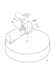
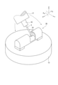
図1において、工作機械1は、ベッド11の上面に移動テーブル12および回転テーブル13を有する。
移動テーブル12は、ベッド11の上面に沿って移動自在に支持され、ベッド11に形成されたX軸移動機構(図示省略)により移動され、X軸方向の所定位置に位置決め可能である。
回転テーブル13は、移動テーブル12の上面に回転自在に設置され、移動テーブル12に形成されたC軸回転機構(図示省略)により回転され、C軸まわりの所定角度位置に位置決め可能である。
回転テーブル13の上面には、加工対象であるワーク2が固定される。
[First Embodiment]
In FIG. 1, the
The moving table 12 is movably supported along the upper surface of the
The rotary table 13 is rotatably installed on the upper surface of the moving table 12, is rotated by a C-axis rotation mechanism (not shown) formed on the moving table 12, and can be positioned at a predetermined angle position around the C-axis.
The
工作機械1は、ベッド11の上面に門型のコラム14を有する。
コラム14は、移動テーブル12のX軸方向の移動経路を跨ぐように門型に形成されている。コラム14には、サドル15およびスライダ16を介して主軸ヘッド17が支持されている。
サドル15は、コラム14の水平バーに沿って移動自在に支持され、コラム14に設置されたY軸移動機構(図示省略)により移動され、Y軸方向の所定位置に位置決め可能である。
スライダ16は、サドル15の垂直な表面に沿って昇降自在に支持され、サドル15に設置されたZ軸移動機構(図示省略)により移動され、Z軸方向の所定位置に位置決め可能である。
The
The
The
The
主軸ヘッド17は、スライダ16の下部表面に回転自在に支持され、スライダ16に形成されたA軸回転機構(図示省略)により回転され、A軸まわりの所定角度位置に位置決め可能である。
主軸ヘッド17には、主軸18が回転自在に支持され、主軸18の先端には工具3が装着される。
主軸18は、主軸ヘッド17に設置されたモータにより回転され、ワーク2の切削加工に必要な所定の回転数およびトルクで工具3を回転させることができる。
The
The
The
工作機械1は、前述した移動テーブル12のX軸移動、サドル15のY軸移動、スライダ16のZ軸移動の3つに、回転テーブル13のC軸回転、主軸ヘッド17のA軸回転の2つを追加した5軸制御により、ワーク2に対して多様な切削加工が可能である。これらの動作制御を行うために、工作機械1にはCNC(コンピュータ数値制御)式の制御装置9が接続されている。
このような工作機械1において、回転テーブル13のC軸の回転軸中心位置を以下の手順で計測する。
The
In such a
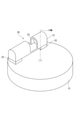
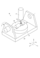
図2において、本実施形態では、工作機械1のC軸中心位置の計測を行うために、回転テーブル13に検出ユニット20を設置する。
図3において、検出ユニット20はケース21を有し、ケース21の両端の脚部22で回転テーブル13の表面に着脱可能である。脚部22は、粘着あるいはマグネットや吸盤などの固定手段を有し、回転テーブル13の表面にずれないように固定される。
In FIG. 2, in the present embodiment, the
In FIG. 3, the
ケース21は中間部上面側に開く開口部23を有する。ケース21の内部には、開口部23を挟んで一方の側に照明部24が設置され、反対側にテレセントリックレンズ25、撮像部であるCCDカメラ26および演算部27が設置されている。
照明部24は、開口部23を通してテレセントリックレンズ25に向けて平行光束28を照射可能である。
平行光束28は、テレセントリックレンズ25により集束され、CCDカメラ26で撮影される。
The
The
The parallel
撮像部であるCCDカメラ26は、入射された集束光から平行光束28の横断画像を検出する。ここで、開口部23に検出対象物29が配置されると、平行光束28の一部が遮断され、影281が形成される。
演算部27は、CCDカメラ26の検出画像を処理し、検出画像に表れる影281における幅および高さを測定することで、検出対象物29の幅および高さを非接触で検出可能である。
The
The
図4において、前述した検出ユニット20の開口部23に工具3の先端を導入することで、工具3の先端が検出対象物29として平行光束28中に配置され、工具3の先端位置を検出することができる。
検出ユニット20は、平行光束28が回転テーブル13の周方向(回転テーブル13の半径方向と直交する方向)となるように、つまり照明部24とCCDカメラ26とが回転テーブル13の周方向に沿って向き合う姿勢としておく。
検出ユニット20の位置は、回転テーブル13の中心から離れた位置であればよく、正確な位置を計測しておく必要はない。また、検出ユニット20の向きも、平行光束28が回転テーブル13の周方向に正確に沿う方向である必要はない。これは、正確でない成分があっても、後述する対向位置(角度位置A0と角度位置A180、角度位置A90と角度位置A270)での演算時に、正確でない成分が相殺されるからである。
工具3を検出ユニット20に導入する際には、工具3の先端位置がCCDカメラ26の検出画像(図5の検出画像261)の中央にくるように位置を調整する。
In FIG. 4, by introducing the tip of the
In the
The position of the
When the
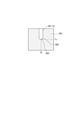
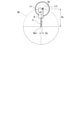
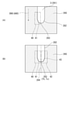
図5において、CCDカメラ26の検出画像261には、工具3の先端の影281が表れる。
検出画像261においては、影281の輪郭282から、工具3の先端位置283の座標(Tv,Th)を正確に割り出すことができる。
検出画像261で検出される座標(Tv,Th)のうち、垂直方向の座標Tvは工作機械1のZ軸座標に相当する。一方、水平方向の座標Thは、回転テーブル13の中心に対する工具3の径方向位置Rc(半径方向の距離)であり、回転テーブル13の角度位置に応じて工作機械1のX軸座標およびY軸座標に投影される。例えば、回転テーブル13が図7(A)の角度位置A0にあるとき、検出画像261は工作機械1のX軸に交差し、座標Thは工作機械1のY軸の座標Tyとなる。回転テーブル13が図8(A)の角度位置A90にあるとき、検出画像261は工作機械1のY軸に交差し、座標Thは工作機械1のX軸の座標Txとなる。
In FIG. 5, the
In the
Of the coordinates (Tv, Th) detected by the detected
工具3の先端位置283の座標(Tv,Th)の割り出しにあたっては、演算部27において検出画像261の画像処理による工具3の先端位置検出を行ってもよく、検出ユニット20を工具3の位置決め治具として用い、工作機械1の位置データを取得して工具3の先端位置としてもよい。この際の工具3の先端位置の検出処理は、検出ユニット20に設置された演算部27で行うことができるほか、検出ユニット20ではCCDカメラ26による画像検出までを行い、検出画像261の処理ないし工具3の先端位置の検出は工作機械1の制御装置9で行ってもよい。
In determining the coordinates (Tv, Th) of the
図6において、工作機械1の制御装置9は、前述した各軸移動などを制御するための動作制御部91を有するとともに、検出ユニット20から取得した検出画像261を画像処理して工具3の先端位置を検出する工具位置検出部92を有する。
検出動作においては、動作制御部91の制御のもとで工作機械1を動作させ、主軸18を移動させて工具3を検出ユニット20の開口部23内に導入し、工具3の先端が検出ユニット20の特定位置にくるように主軸18と回転テーブル13との相対位置を調節する。この状態で、工具位置検出部92は動作制御部91から主軸18の位置データ(工作機械1のZ軸座標、X軸座標およびY軸座標)を取得し、検出画像261における座標Tv,Thを計算し、これを工具3の先端位置とすることができる。
In FIG. 6, the
In the detection operation, the
特定位置としては、検出ユニット20における工具検出領域である開口部23の中心位置などが利用できる。工具3の先端を特定位置に配置するために、CCDカメラ26の検出画像261に特定位置を示すマーカなどを表示することができる。一方、CCDカメラ26の検出画像261の中央位置を特定位置とし、目視確認のみで特定位置と判定してもよい。これは、特定位置が正確でなくても、後述する対向位置(角度位置A0と角度位置A180、角度位置A90と角度位置A270)での演算時に、正確でない成分が相殺されるからである。
As the specific position, the center position of the
本実施形態では、上述した検出ユニット20を用いて、工作機械1のC軸中心位置を以下の手順で計測する。
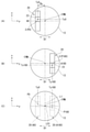
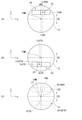
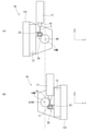
図7(A)において、先ず回転テーブル13を角度位置A0とし、回転テーブル13の中心から離れた位置に検出ユニット20を置く。
回転テーブル13の角度位置A0は、CCDカメラ26の光軸が工作機械1のX軸に沿った状態とする。ただし角度位置A0は任意の角度でよい。
In the present embodiment, the C-axis center position of the
In FIG. 7A, first, the rotary table 13 is set to the angular position A0, and the
The angle position A0 of the rotary table 13 is such that the optical axis of the
検出ユニット20を設置したら、回転テーブル13の上方から主軸18(図1参照)を下降させ、工具3を検出ユニット20の開口部23に導入する。そして、検出ユニット20により角度位置A0における工具3の位置P0(Tx0,Ty0)を記録しておく。
After installing the
次に、工具3を上昇させて検出ユニット20から抜き出したうえ、検出ユニット20を載せたまま回転テーブル13を角度位置A0から180度回転させ、角度位置A0に対してC軸を挟んで第1方向D1に対向する角度位置A180とする。
図7(B)において、回転テーブル13が角度位置A180にある状態で、再び工具3を検出ユニット20に導入する。そして、検出ユニット20により角度位置A180における工具3の先端位置P180(Tx180,Ty180)を記録しておく。
Next, after raising the
In FIG. 7B, the
図7(C)において、角度位置A0位置および角度位置A180での工具3の位置P0,P180が得られたら、演算部27により、C軸中心位置を通りかつ第1方向D1と交差する第1直線L1を計算する。具体的には、角度位置A0での工具3の位置P0と角度位置A180での工具3の先端位置P180とを線分L01で結び、その中点を通りかつ第1方向D1と交差する直線を第1直線L1とする。
In FIG. 7C, when the positions P0 and P180 of the
図7(A)~図7(C)の検出動作により第1直線L1が得られたら、同様の手順で第2直線L2を計算する。
図8(A)において、検出ユニット20および回転テーブル13を角度位置A90(角度位置A0から90度回転した角度位置)とし、工具3を検出ユニット20の開口部23に導入する。そして、検出ユニット20により角度位置A90における工具3の先端位置P90(Tx90,Ty90)を記録しておく。
図8(B)において、同様の操作により、検出ユニット20および回転テーブル13を、角度位置A90に対してC軸を挟んで第2方向D2(第1方向D1と交差する)に対向する角度位置A270とし、検出ユニット20により角度位置A270における工具3の先端位置P270(Tx270,Ty270)を記録しておく。
When the first straight line L1 is obtained by the detection operations of FIGS. 7A to 7C, the second straight line L2 is calculated by the same procedure.
In FIG. 8A, the
In FIG. 8B, by the same operation, the
図8(C)において、角度位置A90および角度位置A270での工具3の先端位置P90,P270が得られたら、演算部27により、C軸中心位置を通りかつ第2方向D2と交差する第2直線L2を計算する。具体的には、角度位置A90での工具3の先端位置P90と角度位置A270での工具3の先端位置P270とを線分L02で結び、その中点を通りかつ第2方向D2と交差する直線を第2直線L2とする。
図9において、第1直線L1および第2直線L2が得られたら、演算部27により第1直線L1と第2直線L2との交点Pcを計算する。これにより、C軸中心位置の存在可能範囲が交点Pcの1点に限定され、工作機械1の正確なC軸中心位置を計測することができる。
In FIG. 8C, when the tip positions P90 and P270 of the
In FIG. 9, when the first straight line L1 and the second straight line L2 are obtained, the
このような本実施形態によれば、次のような効果がある。
本実施形態では、主軸18に工具3を装着し、工具3の位置を非接触で検出可能な検出ユニット20を回転テーブル13に設置しておき、計測対象のC軸について工具3と回転テーブル13とを所定の角度位置(A0,A90,A180,A270)に割り出し、各角度位置で検出ユニット20により回転テーブル13に対する工具3の位置(P0,P90,P180,P270)を検出する検出動作を繰り返し、4回の検出動作で検出された各角度位置での工具3の位置からC軸の中心位置(Pc)を計算した。
According to the present embodiment as described above, there are the following effects.
In the present embodiment, the
このような本実施形態では、非接触式の検出ユニット20を用いた検出動作を4回繰り返し、各角度位置での工具3の位置から幾何学的な計算を行うことで、C軸の中心位置(Pc)を高精度に計測することができる。
計測にあたって、工作機械1の主軸18には加工用の工具3を装着でき、計測の直前に主軸18を回転させて昇温させ、加工時と同様な状態で計測することができる。また、主軸18にタッチプローブが装着できない工作機械1にも、幅広く適用できる。
従って、本実施形態によれば、タッチプローブを用いずに単純な計算でC軸の中心位置を高精度に計測できる。
In such an embodiment, the detection operation using the non-contact
In the measurement, the
Therefore, according to the present embodiment, the center position of the C axis can be measured with high accuracy by a simple calculation without using a touch probe.
本実施形態では、とくに工具3の回転テーブル13の径方向の位置を検出可能な検出ユニット20を用い、工具3と回転テーブル13とを、C軸を挟んで第1方向D1に対向する2つの角度位置A0,A180、およびC軸を挟んで第1方向D1と交差する第2方向D2に対向する2つの角度位置A90,A270の4つの角度位置に割り出し、各角度位置で検出動作を行って工具3の回転テーブル13の径方向の位置(P0,P90,P180,P270)を検出し、第1方向D1に対向する2つの角度位置A0,A180で検出された工具3の位置P0,P180を結ぶ線分L01の中点を通りかつ第1方向D1に交差する第1直線L1と、第2方向D2に対向する2つの角度位置A90,A270で検出された工具3の位置P90,P270を結ぶ線分L02の中点を通りかつ第2方向D2に交差する第2直線L2とを計算し、第1直線L1と第2直線L2との交点PcをC軸の中心位置として計測した。
In this embodiment, in particular, a
このため、本実施形態の検出ユニット20としては、回転テーブル13の径方向の工具3の位置を検出可能であればよく、工具3の側面からの検出画像261(図5参照)を検出して画像上の工具3の位置を検出する画像センサ(照明部24ないしCCDカメラ26、図3参照)を、回転テーブル13の周方向に向けて設置したものが利用できる。
このような本実施形態によれば、0度と180度の角度位置A0、A180での検出動作では確定できないC軸中心位置の推定範囲(直線L1)を、90度と270度の角度位置A90,A270での検出動作による工具3の位置(直線L2)により絞り込み、正確なC軸の中心を確定することができ、計4つの角度位置(A0,A90,A180,A270)での検出動作で、C軸の中心位置を高精度に計測できる。
Therefore, the
According to this embodiment, the estimated range (straight line L1) of the C-axis center position, which cannot be determined by the detection operation at the angle positions A0 and A180 of 0 degree and 180 degrees, is set to the angle position A90 of 90 degrees and 270 degrees. , The position of the tool 3 (straight line L2) by the detection operation at A270 can be narrowed down to determine the exact center of the C axis, and the detection operation at a total of four angular positions (A0, A90, A180, A270) , The center position of the C axis can be measured with high accuracy.
本実施形態では、検出ユニット20は、平行光束28を照射する照明部24と、平行光束28を検出する撮像部(テレセントリックレンズ25およびCCDカメラ26)と、検出画像261から平行光束28中に配置された工具3の先端位置を検出する演算部27と、を有するものとし、検出画像261に対して既存の画像処理を行うことにより、平行光束28中に配置された工具3の影281を検出し、エッジ検出により工具3の先端の輪郭282からその中心位置を演算することで、工具3の先端位置283を計算することができる。
その結果、検出ユニット20により、光学式の検出を行うことで、工具3の先端位置を非接触で高精度に検出することができる。
また、位置検出にあたっては、照明部24と撮像部(テレセントリックレンズ25およびCCDカメラ26)との間の平行光束28の中に工具3の先端を配置するだけでよく、検出操作が容易である。
本実施形態では、検出ユニット20は、回転テーブル13に対する固定手段を有するとしたため、検出ユニット20の回転テーブル13に対する設置位置が、各角度位置での検出動作の間に変動しないようにできる。
In the present embodiment, the
As a result, the
Further, in the position detection, it is only necessary to arrange the tip of the
In the present embodiment, since the
〔第2実施形態〕
図10には、本発明の第2実施形態が示されている。
前述した第1実施形態では、工作機械1(図1参照)のC軸中心位置の計測を行うために、回転テーブル13に検出ユニット20を設置し(図2および図3参照)、角度位置A0,A180での工具3の径方向位置の検出動作により第1直線L1を検出し、角度位置A90,A270での同検出動作により第2直線L2を検出し、その交点Pcを工作機械1の正確なC軸中心位置として計測していた。
これに対し、本実施形態では、角度位置A0,A180での検出動作において工具3の径方向位置とともに周方向位置、つまり回転テーブル13の表面に沿った平面位置を検出することで、工作機械1の正確なC軸中心位置を計測する。
[Second Embodiment]
FIG. 10 shows a second embodiment of the present invention.
In the first embodiment described above, in order to measure the C-axis center position of the machine tool 1 (see FIG. 1), the
On the other hand, in the present embodiment, in the detection operation at the angle positions A0 and A180, the
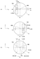
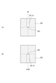
図10(A)において、角度位置A0にある回転テーブル13には検出ユニット20Aが置かれている。
検出ユニット20Aは、基本構成が第1実施形態の検出ユニット20と同様であり、さらに、オートフォーカス機能を利用した画像の奥行き方向の座標検出が可能である。オートフォーカス機能を用いた座標検出としては、例えば図5の検出画像261において、工具3の影281の輪郭282に対してエッジ検出を行い、コントラスト最大となる焦点位置を検出することで、画像の奥行き方向の座標を正確に検出できる。
従って、回転テーブル13に置かれた検出ユニット20Aに工具3を導入することにより、回転テーブル13に対する工具3の径方向位置Rcおよび周方向位置Ccを検出することができる。このような、角度位置A0における検出動作により、工具3の回転テーブル13に対する平面位置PA0が計測される。
In FIG. 10A, the
The
Therefore, by introducing the
図10(B)において、角度位置A0での検出動作が済んだら、回転テーブル13を角度位置A180へ移動させ、角度位置A180で同様の検出動作を行うことで、工具3の回転テーブル13に対する平面位置PA180が計測される。
図10(C)において、平面位置PA0および平面位置PA180が得られたら、演算部27により平面位置PA0と平面位置PA180とを結ぶ線分LAの中点PAcを計算する。この中点PAcにより、工作機械1の正確なC軸中心位置を計測できる。
In FIG. 10B, after the detection operation at the angle position A0 is completed, the rotary table 13 is moved to the angle position A180, and the same detection operation is performed at the angle position A180. Position PA180 is measured.
In FIG. 10C, when the plane position PA0 and the plane position PA180 are obtained, the
このような本実施形態によれば、前述した第1実施形態と同様な効果が得られるとともに、工具3の先端の検出動作が角度位置A0,A180の2箇所で済み、作業効率を向上することができる。
さらに、本実施形態では、第1実施形態における角度位置A90,A270など、他の角度位置での検出動作が必要ないため、例えば角度位置A90,A270が並進軸(XYZ軸)の構造的な制約により検出動作の範囲外となる工作機械1であっても、角度位置A0,A180での検出動作により正確なC軸中心位置を計測できる。
According to the present embodiment as described above, the same effect as that of the first embodiment described above can be obtained, and the detection operation of the tip of the
Further, in the present embodiment, since the detection operation at other angle positions such as the angle positions A90 and A270 in the first embodiment is not required, for example, the angle positions A90 and A270 are structurally restricted by the translation axis (XYZ axis). Therefore, even if the
〔第3実施形態〕
図11ないし図12には、本発明の第3実施形態が示されている。
前述した第1実施形態では角度位置A0,A180および角度位置A90,A270での検出動作を行い、第2実施形態では角度位置A0,A180での検出動作を行っており、それぞれ回転テーブル13の中心を挟んで対向する角度位置A0,A180での検出動作が必要であった。
これに対し、本実施形態では、角度位置A0から180度未満の複数の角度位置Anでそれぞれ第1実施形態と同様に、工具3の先端位置の検出動作を行い、検出結果の演算により工作機械1の正確なC軸中心位置を計測する。
本実施形態において、工作機械1、回転テーブル13および検出ユニット20については前述した第1実施形態と同様であり、これらの構成に関する重複する説明は省略する。
[Third Embodiment]
11 to 12 show a third embodiment of the present invention.
In the first embodiment described above, the detection operation is performed at the angle positions A0 and A180 and the angle positions A90 and A270, and in the second embodiment, the detection operation is performed at the angle positions A0 and A180. It was necessary to perform a detection operation at the angle positions A0 and A180 facing each other.
On the other hand, in the present embodiment, the detection operation of the tip position of the
In the present embodiment, the
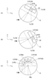
図11(A)において、先ず、検出ユニット20が設置された回転テーブル13を角度位置A0に配置し、検出ユニット20の開口部23に工具3の先端を導入し、その位置を検出ユニット20で検出して工具3の位置P0とする。
図11(B)において、次に、回転テーブル13を30度回転させて次の角度位置A30まで回転させ、角度位置A0と同様な操作により工具3の位置P30を検出する。
図11(C)において、さらに回転テーブル13を30度回転させて次の角度位置A60まで回転させ、角度位置A0と同様な操作により工具3の位置P60を検出する。
図12(A)において、回転テーブル13を次の角度位置A120まで回転させ、角度位置A0と同様な操作により工具3の位置P120を検出する。
図12(B)において、回転テーブル13を次の角度位置A150まで回転させ、角度位置A0と同様な操作により工具3の位置P150を検出する。
In FIG. 11A, first, the rotary table 13 in which the
In FIG. 11B, the rotary table 13 is then rotated by 30 degrees to be rotated to the next angle position A30, and the position P30 of the
In FIG. 11C, the rotary table 13 is further rotated by 30 degrees to be rotated to the next angle position A60, and the position P60 of the
In FIG. 12A, the rotary table 13 is rotated to the next angle position A120, and the position P120 of the
In FIG. 12B, the rotary table 13 is rotated to the next angle position A150, and the position P150 of the
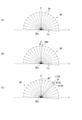
図12(C)において、前述した角度位置A0~A150で検出された工具3の位置P0~P150は画面上にプロットした際に円弧状に並ぶことになる。円弧状に並んだ位置P0~P150の点列に対して、例えば最小二乗法などにより、円弧状の中心点PBcの位置を高精度に計算することができ、ここで得られた中心点PBcを工作機械1の正確なC軸中心位置として計測することができる。
In FIG. 12C, the positions P0 to P150 of the
このような本実施形態によっても、前述した第1実施形態と同様な効果が得られるとともに、工作機械1における並進軸(XYZ軸)の構造的な制約により検出動作の可能範囲が180度未満であっても、複数位置での検出動作により正確なC軸中心位置を計測できる。
Even with this embodiment, the same effect as that of the first embodiment described above can be obtained, and the possible range of the detection operation is less than 180 degrees due to the structural restriction of the translational axis (XYZ axis) in the
〔第1~第3実施形態の変形〕
前述した第1~第3実施形態においては、角度位置Anでの検出動作の際に、検出ユニット20で工具3の先端の画像を撮影したが、工具3の検出画像上の位置は角度位置Anごとにずれていてもよい。
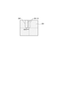
図13において、検出ユニット20の検出画像261において、工具3の影281の輪郭282の検出画像261上の位置は、角度位置A0と他の角度位置Anで常に同じ位置にならないことがある。しかし、検出画像261の画像処理によって、角度位置A0(2点鎖線)の位置からのずれ量dc0が算出できれば、その分の補正により工具3の座標を確定することができ、工具3の検出画像261上の位置は角度位置Anごとにずれていてもよい。
[Modifications of the first to third embodiments]
In the first to third embodiments described above, an image of the tip of the
In FIG. 13, in the
〔第4実施形態〕
図14ないし図16には、本発明の第4実施形態が示されている。
本実施形態は、工作機械1におけるA軸中心位置から工具3の先端までのずれの距離(オフセット量)を計測するものである。
本実施形態における工作機械1、および計測に用いる検出ユニット20については、前述した第1実施形態と同様であるので、重複する説明は省略する。
[Fourth Embodiment]
14 to 16 show a fourth embodiment of the present invention.
In this embodiment, the distance (offset amount) of the deviation from the center position of the A-axis to the tip of the
Since the
本実施形態では、回転テーブル13に検出ユニット20を設置する。
検出ユニット20は開口部23が回転テーブル13の中央(C軸回転中心位置)にくるように配置する。そして、平行光束28の向きが工作機械1のX軸方向となるように検出ユニット20の向きを調整しておく。検出ユニット20の向きは、回転テーブル13のC軸回転によって調整してもよい。
検出ユニット20が設置できたら、工作機械1の各軸動作により主軸ヘッド17を検出ユニット20に接近させ、主軸18に装着された工具3の先端を開口部23に導入して検出動作を行う。
In this embodiment, the
The
After the
図15(A)において、先ず、工作機械1のA軸回転により、工具3がY軸「+」方向に向いた状態(A軸まわりの角度位置A0)とし、この状態で工作機械1の各軸移動により工具3の先端を開口部23に導入する。さらに、工作機械1のY軸およびZ軸の移動により、検出ユニット20で得られる検出画像262において工具3の影281の先端位置283が検出画像262の中央にくるように調整し、この時の工作機械1のY軸位置およびZ軸位置(図16のY1,Z1)を記録しておく。
In FIG. 15A, first, the A-axis rotation of the
図15(B)において、次に、工作機械1のA軸回転により、工具3がY軸「-」方向に向いた状態(A軸を挟んで角度位置A0と対向する角度位置A180)とし、この状態で工作機械1の各軸移動により工具3の先端を開口部23に導入する。さらに、工作機械1のY軸およびZ軸の移動により、検出ユニット20で得られる検出画像262において工具3の影281の先端位置283が検出画像262の中央にくるように調整し、この時の工作機械1のY軸位置およびZ軸位置(図16のY2,Z2)を記録しておく。
In FIG. 15B, next, the A-axis rotation of the
図16において、角度位置A0での工作機械1のY軸位置Y1およびZ軸位置Z1と、角度位置A180での工作機械1のY軸位置Y2およびZ軸位置Z2との差は、それぞれ工具3の先端を同じ位置に配置した結果、A軸(主軸ヘッド17の回転軸171)における回転中心の振れに基づいている。
従って、角度位置A0および角度位置A180での各軸位置の差分の1/2から、工作機械1のA軸中心位置から工具3の先端までのずれの距離(オフセット量)(Y=(Y1-Y2)/2,Z=(Z1-Z2)/2)が計測できる。
このような本実施形態によっても、A軸中心位置から工具3の先端までのずれの距離(オフセット量)の計測にあたって、前述した第1実施形態と同様な効果が得られる。
In FIG. 16, the difference between the Y-axis position Y1 and the Z-axis position Z1 of the
Therefore, the distance (offset amount) of the deviation from the A-axis center position of the
Even with this embodiment as described above, the same effect as that of the first embodiment described above can be obtained in measuring the distance (offset amount) of the deviation from the center position of the A-axis to the tip of the
〔第5実施形態〕
図17ないし図20には、本発明の第5実施形態が示されている。
本実施形態は、いわゆる揺りかご式の工作機械1AにおけるA軸中心位置と工具3の先端が一致する座標を計測するものである。
図17において、回転テーブル13はクレードル131を介して移動テーブル12(図1参照)に支持され、クレードル131に対してC軸まわりに回転可能である。クレードル131は一対のトラニオン132により移動テーブル12に対してA軸まわりに回転可能である。
なお、工作機械1Aにおいては、主軸ヘッド17はスライダ16(図1参照)に対して固定され、A軸回転は行わず、常にZ軸下向きに保持されている。
[Fifth Embodiment]
17 to 20 show a fifth embodiment of the present invention.
In this embodiment, the coordinates at which the center position of the A-axis and the tip of the
In FIG. 17, the rotary table 13 is supported by the moving table 12 (see FIG. 1) via the
In the
本実施形態では、回転テーブル13に検出ユニット20を設置する。検出ユニット20については、前述した第1実施形態と同様であるので、重複する説明は省略する。
検出ユニット20は開口部23が回転テーブル13の中央(C軸回転中心位置)にくるように配置する。そして、平行光束28の向きが工作機械1AのX軸方向となるように検出ユニット20の向きを調整しておく。検出ユニット20の向きは、回転テーブル13のC軸回転によって調整してもよい。
検出ユニット20が設置できたら、工作機械1Aの各軸動作により主軸ヘッド17を検出ユニット20に接近させ、主軸18に装着された工具3の先端を開口部23に導入して検出動作を行う。
In this embodiment, the
The
After the
図18(A)において、先ず、クレードル131のA軸回転により、回転テーブル13がY軸「+」方向に向いた状態(A軸まわりの角度位置A0)とし、この状態で工作機械1Aの各軸移動により工具3の先端を開口部23に導入する。
図19(A)において、クレードル131を角度位置A0とした状態で、工作機械1AのY軸およびZ軸の移動により、検出ユニット20で得られる検出画像263において工具3の影281の先端位置283が検出画像263の中央にくるように調整し、この時の工作機械1AのY軸位置およびZ軸位置(図20のY1,Z1)を記録しておく。
In FIG. 18A, first, the rotary table 13 is oriented in the Y-axis “+” direction (angle position A0 around the A-axis) by rotating the
In FIG. 19A, the
図18(B)において、続いて、クレードル131のA軸回転により、回転テーブル13がY軸「-」方向に向いた状態(A軸を挟んで角度位置A0と対向する角度位置A180)とし、この状態で工作機械1Aの各軸移動により工具3の先端を開口部23に導入する。
図19(B)において、クレードル131を角度位置A180とした状態で、工作機械1AのY軸およびZ軸の移動により、検出ユニット20で得られる検出画像263において工具3の影281の先端位置283が検出画像263の中央にくるように調整し、この時の工作機械1AのY軸位置およびZ軸位置(図20のY2,Z2)を記録しておく。
In FIG. 18B, subsequently, by rotating the
In FIG. 19B, with the
図20において、角度位置A0での工作機械1AのY軸位置Y1およびZ軸位置Z1と、角度位置A180での工作機械1AのY軸位置Y2およびZ軸位置Z2との差は、それぞれ工具3の先端を同じ位置に配置した結果、クレードル131のA軸回転中心の振れに基づいている。
従って、角度位置A0および角度位置A180での各軸位置から、式(Y=(Y1+Y2)/2,Z=(Z1+Z2)/2)により、工作機械1AのA軸中心位置と工具3の先端が一致する座標が計測できる。
このような本実施形態によっても、A軸中心位置と工具3の先端が一致する座標の計測にあたって、前述した第1実施形態と同様な効果が得られる。
In FIG. 20, the difference between the Y-axis position Y1 and the Z-axis position Z1 of the
Therefore, from each axis position at the angle position A0 and the angle position A180, the A-axis center position of the
Even with this embodiment as described above, the same effect as that of the first embodiment described above can be obtained in measuring the coordinates at which the center position of the A axis and the tip of the
〔第6実施形態〕
図21ないし図23には、本発明の第6実施形態が示されている。
本実施形態は、前述した第4実施形態と同様の構成を用いて、工作機械1におけるA軸中心位置から工具3の先端までのずれの距離(オフセット量)を計測するものである。
ただし、第4実施形態が角度位置A0と、A軸を挟んで角度位置A0と対向する(つまり180度間隔となる)角度位置A180との、2箇所で工作機械1のY軸位置Y1,Y2およびZ軸位置Z1,Z2を検出したのに対し、本実施形態では、角度位置A0から180度の範囲内の複数の角度位置AnでY軸位置およびZ軸位置の検出動作を行う。
[Sixth Embodiment]
21 to 23 show a sixth embodiment of the present invention.
In this embodiment, the distance (offset amount) of the deviation from the center position of the A-axis in the
However, in the fourth embodiment, the Y-axis positions Y1 and Y2 of the
図21(A)において、先ず、工作機械1のA軸回転(主軸ヘッド17の回転軸171の回転)により、工具3がY軸「+」方向に向いた状態(A軸まわりの角度位置A0)とし、この状態で工作機械1の各軸移動により工具3の先端を開口部23に導入する。
図21(B)において、工具3が角度位置A0に配置されたのち、工作機械1のY軸およびZ軸の移動により、検出ユニット20で得られる検出画像264において工具3の影281の先端位置283が検出画像264の中央にくるように調整し、この時の工作機械1のY軸位置およびZ軸位置を記録しておく。記録されるY軸位置およびZ軸位置は、各角度位置AnにおけるA軸中心位置Q0となる。
In FIG. 21A, first, the
In FIG. 21B, after the
続いて、工作機械1のA軸回転により、工具3を角度位置A30(角度位置A0から30度回転した状態)とし、この状態で角度位置A0と同様に、工作機械1の各軸移動により工具3の先端を開口部23に導入し、検出ユニット20で得られる検出画像264において工具3の影281の先端位置283が検出画像264の中央にくるように調整し、その時の工作機械1のY軸位置およびZ軸位置(A軸中心位置Q30)を記録する。
さらに、工作機械1のA軸回転により、工具3を角度位置A60(角度位置A0から60度回転した状態)とし、角度位置A0,A30と同様な手順で工作機械1のY軸位置およびZ軸位置(A軸中心位置Q60)を記録する。
同様にして、角度位置A90,A120,A150,A180における工作機械1のY軸位置およびZ軸位置(A軸中心位置Q90,Q120,Q150,Q180)を記録してゆく。
Subsequently, the
Further, by rotating the A-axis of the
Similarly, the Y-axis position and the Z-axis position (A-axis center positions Q90, Q120, Q150, Q180) of the
図21(C)において、上述の検出動作を繰り返して得られた角度位置An(A0~A180)におけるA軸中心位置Qn(Q0~Q180)を画面上にプロットすると、これらは円弧状に並んだ点列QCとなる。これらの点列QCに対して、例えば最小二乗法などにより、円弧状の点列QCの中心点QCcの位置(各角度位置Anに共通の工具3の先端位置)を高精度に計算することができる。ここで得られた中心点QCcにより、工作機械1のA軸中心位置Qnから工具3の先端までのずれの距離(オフセット量)を正確に計測することができる。
In FIG. 21C, when the A-axis center positions Qn (Q0 to Q180) at the angular positions An (A0 to A180) obtained by repeating the above detection operation are plotted on the screen, they are arranged in an arc shape. It becomes a point sequence QC. For these point sequences QC, the position of the center point QCc of the arcuate point sequence QC (the tip position of the
このような本実施形態によっても、前述した第1実施形態および第4実施形態と同様な効果が得られるとともに、工作機械1における並進軸(XYZ軸)の構造的な制約により検出動作の可能範囲が180度未満であっても、複数の角度位置Anでの検出動作によりA軸中心位置Qnから工具3の先端までのずれの距離(オフセット量)を正確に計測できる。
Even with this embodiment as described above, the same effects as those of the first embodiment and the fourth embodiment described above can be obtained, and the possible range of the detection operation due to the structural restriction of the translational axis (XYZ axis) in the
〔第6実施形態の変形例〕
図22において、前述した第6実施形態で計測されたA軸中心位置Qnから工具3の先端までのずれの距離(オフセット量)は、工作機械1のNC装置に登録され、工作機械1の動作時の補正値として参照される。
工作機械1のNC装置に登録する際には、工具3の先端位置である中心点QCcから実際のA軸中心位置Qnまでの距離D(オフセット量)が必要になる。A軸中心位置Qnによる円弧状の点列QCの最小二乗法演算により、中心点QCcの位置とともに中心点QCcからA軸中心位置Qnまでの距離D(近似値)を示す近似円弧半径が得られるので、この半径を中心点QCcとA軸中心位置Qnとの実際の距離Dとすることができる。
[Variation example of the sixth embodiment]
In FIG. 22, the distance (offset amount) of the deviation from the A-axis center position Qn measured in the sixth embodiment described above to the tip of the
When registering in the NC device of the
工作機械1のNC装置に登録する場合、距離Dを工具3に平行なZ軸方向の成分Dzと工具3と直交するY軸方向の成分Dyに分離しなければならない。このために、A軸中心位置Qnと工具3の先端(中心点QCc)とを結ぶ線分の角度θが必要となる。しかし、中心点QCcの計算に用いた最小二乗法では、近似円弧半径(距離D)を与える線分の角度θは得られない。
図23(A)において、前述した角度θが得られないことに加えて、前述した複数の角度位置An(A0~A180)で円弧状の点列QCとして検出されるA軸中心位置Qn(サンプリング点)は、点列QCの近似円弧に対してばらつき(径方向の変位)がある。また、A軸中心位置Qnを検出する角度位置Anとされる角度(0度~180度)で中心点QCcから延びる基準線Lnを引くと、各角度でのA軸中心位置Qnはこれらの基準線Lnに対してもばらつき(周方向の変位)をもっている。
このような誤差分布の下で、先の角度θの最適値を決定するために、以下のような操作を採用することができる。
When registering in the NC device of the
In FIG. 23A, in addition to not being able to obtain the above-mentioned angle θ, the A-axis center position Qn (sampling) detected as an arcuate point sequence QC at the above-mentioned plurality of angle positions An (A0 to A180). The points) have variations (displacements in the radial direction) with respect to the approximate arc of the point sequence QC. Further, when the reference line Ln extending from the center point QCc is drawn at an angle (0 degree to 180 degrees) set as the angle position An for detecting the A-axis center position Qn, the A-axis center position Qn at each angle is these references. There is also variation (displacement in the circumferential direction) with respect to the line Ln.
Under such an error distribution, the following operation can be adopted to determine the optimum value of the above angle θ.
図23(B)において、第1の操作として、工具3がZ軸に沿った向き(角度位置A90)でのA軸中心位置Q90を採用してしまうことである。具体的には、中心点QCcからA軸中心位置Q90に伸ばした線分を求め、この線分とZ軸とのなす角度をθとする。
このような操作によれば、全体最適にはならないが、基準としては最もふさわしい。
In FIG. 23B, as the first operation, the
Such an operation does not result in overall optimization, but is the most suitable standard.
図23(C)において、第2の操作として、工具3がZ軸に対して所定角度(例えば40度)となる向き(角度位置A0から130度の角度位置A130)において、中心点QCcからA軸中心位置Q130に伸ばした線分を求め、この線分とZ軸から40度をなす基準線L130とのなす角度をθとしてもよい。
In FIG. 23C, as a second operation, the center point QCc to A in the direction (angle position A130 from the angle position A0 to 130 degrees) at which the
さらに、複数の角度位置AnにあるA軸中心位置Qnにおいて、基準線Lnとの角度θnを求め、その平均値を求めてもよい。
このような操作によれば、操作が煩雑であるが、全体最適となる角度θを得ることができる。
前述した複数の角度位置AnにあるA軸中心位置Qnにおいては、全範囲を均等割りして角度θを求めてもよいが、一部の角度範囲のサンプリング密度を高めたりあるいは低くしたりしてもよい。
以上の操作により、角度θが得られたら、前述したZ軸方向の成分Dzと工具3と直交するY軸方向の成分Dy(図22参照)は、それぞれDz=Dcosθ、Dy=Dsinθとして計算することができる。
Further, at the A-axis center position Qn at the plurality of angle positions An, the angle θn with the reference line Ln may be obtained, and the average value thereof may be obtained.
According to such an operation, although the operation is complicated, it is possible to obtain an angle θ that is optimal overall.
At the A-axis center position Qn at the plurality of angle positions An described above, the entire range may be evenly divided to obtain the angle θ, but the sampling density of some of the angle ranges may be increased or decreased. May be good.
After the angle θ is obtained by the above operation, the above-mentioned component Dz in the Z-axis direction and the component Dy in the Y-axis direction orthogonal to the tool 3 (see FIG. 22) are calculated as Dz = Dcosθ and Dy = Dsinθ, respectively. be able to.
〔第1~第6実施形態の変形〕
前述した第1ないし第6の各実施形態においては、それぞれ検出ユニット20,20Aにより工具3の先端位置を検出した。
例えば、第1実施形態では、図5に示すように、CCDカメラ26の検出画像261の中央に工具3の先端位置を捉え、検出画像261に表れる工具3の先端の影281の輪郭282から、工具3の先端位置283の座標(Tv,Th)を割り出していた。
この際、工具3の先端の凹凸形状が複雑であるなど、工具3の先端形状によっては、座標が正確に検出できないことがある。
これに対し、工具3の先端位置(Tv,Th)を簡単かつ正確に検出するために、以下に示す手順が利用できる。
[Modifications of the first to sixth embodiments]
In each of the first to sixth embodiments described above, the tip position of the
For example, in the first embodiment, as shown in FIG. 5, the tip position of the
At this time, the coordinates may not be accurately detected depending on the shape of the tip of the
On the other hand, in order to easily and accurately detect the tip position (Tv, Th) of the
〔第7実施形態〕
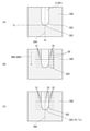
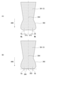
図24(A)に示すように、CCDカメラ26(図3参照)の検出画像261には、工具3の先端の影281が表れる(図5と同様)。影281の輪郭282の一部には、工具3の先端位置283が表れ、その座標(Tv,Th)の計測が求められる。
本実施形態では、工具3をCCDカメラ26に対して回転させた状態で、CCDカメラ26で検出画像265を検出し(第1~第6実施形態における検出画像261~264と同様)、検出画像265から工具3の輪郭282を検出する。
本実施形態では、工具3が回転していることで、検出画像265に表れる輪郭282は回転中心に対して対称となり、この輪郭282の対称性から工具3の中心軸線284を正確に検出し、中心軸線284と輪郭282との交点を工具3の先端位置283として検出することができる。
[7th Embodiment]
As shown in FIG. 24A, a
In the present embodiment, the
In the present embodiment, since the
本実施形態において、輪郭282から工具3の中心軸線284を検出する際には、次のような演算処理を行う。
図24(B)に示すように、検出画像265において、工具3を所定の角度位置(例えば図21(B)に示す角度位置A90)に配置し、その際の工具3の延伸方向D90とする。次に、延伸方向D90に沿って所定間隔で平行に、延伸方向D90に直交しつつ輪郭282を横断する複数の横断線30を設定してゆく。
図24(C)に示すように、設定した複数の横断線30に対して、それぞれ輪郭282との2つの交点31,32を検出し、さらに2つの交点31,32の中点33を検出する。そして、各横断線30の中点33を通る直線を検出することで、この直線を工具3の中心軸線284とすることができる。
In the present embodiment, when the
As shown in FIG. 24B, in the
As shown in FIG. 24C, two
このような本実施形態では、工具3の延伸方向Dn(各角度位置An,工具3の向き、概略的な軸線方向)を利用して、回転対称の軸を検出することで、工具3の正確な中心軸線284を検出でき、正確な中心軸線284と輪郭282との交点から、工具3の先端位置283の座標(Th,Tv)を高精度に検出できる。
この際、中心軸線284の検出には複数の横断線30の中点検出を行い、先端位置283の検出には輪郭282との交点検出を行うことで、それぞれは幾何学的な演算処理で実行でき、これにより工具3の先端位置283ないし回転軸(A軸あるいはC軸)の中心位置を高精度に、かつ簡単に計測できる。
In such an embodiment, the extension direction Dn of the tool 3 (each angle position An, the direction of the
At this time, the detection of the
本実施形態において、工具3の向き(延伸方向Dn)は任意の角度(角度位置An)とすることができる。
図25(A)において、工具3は角度位置A150とされ、延伸方向D150に直交する複数の横断線30が設定される。
図25(B)に示すように、各横断線30においては2つの交点31,32および中点33が検出され、複数の中点33を通る中心軸線284と輪郭282との交点から工具3の先端位置283の座標(Th,Tv)を正確に検出できる。
In the present embodiment, the orientation of the tool 3 (stretching direction Dn) can be any angle (angle position An).
In FIG. 25A, the
As shown in FIG. 25B, two
〔第8実施形態〕
前述した第7実施形態では、輪郭282から工具3の中心軸線284を検出する際に、複数の横断線30の中点検出を行った。
これに対し、本実施形態では、回転対称図形である輪郭282の片側ずつのパターン認識により工具3の中心軸線284を検出する。
図26(A)に示すように、検出画像265において、工具3を所定の角度位置(例えば図21(B)に示す角度位置A90)に配置し、その際の工具3の延伸方向D90とする。次に、延伸方向D90に対して輪郭282の片側(延伸方向D90に沿った直線で輪郭282を2分割した一部)の形状41を基準パターン40として検出する。
図26(B)に示すように、基準パターン40が検出できたら、基準パターン40を反転した形状に合致する対称パターン42を演算し、この対称パターン42に一致する形状43を輪郭282から検出する。対称パターン42が検出できたら、基準パターン40と対称パターン42との中間を通る直線(基準パターン40と対称パターン42との線対称の軸)を工具3の中心軸線284とする。
[Eighth Embodiment]
In the seventh embodiment described above, when the
On the other hand, in the present embodiment, the
As shown in FIG. 26 (A), in the
As shown in FIG. 26B, when the
このような本実施形態では、工具3の延伸方向Dn(各角度位置An,工具3の向き、概略的な軸線方向)を利用し、輪郭282の片側ずつのパターン認識により、工具3の正確な中心軸線284を検出でき、正確な中心軸線284と輪郭282との交点から、工具3の先端位置283の座標(Th,Tv)を高精度に検出できる。
この際、輪郭282の片側ずつのパターン認識として、基準パターン40および対称パターン42の検出は、それぞれ幾何学的な演算処理で実行でき、これにより工具3の先端位置283ないし回転軸(A軸あるいはC軸)の中心位置を高精度に、かつ簡単に計測できる。
In such an embodiment, the extension direction Dn of the tool 3 (each angle position An, the direction of the
At this time, as pattern recognition for each side of the
〔第9実施形態〕
前述した第7実施形態では、輪郭282から工具3の中心軸線284を検出したのち、中心軸線284と輪郭282との交点を検出して工具3の先端位置283とした。
これに対し、本実施形態では、工具3の先端部の輪郭282に補助輪郭線を設定することで、先端に複数の突起をもつ工具3や、中心から偏った先端をもつ工具3など、回転した状態では先端部の輪郭282の形状が不明瞭になる工具3についても、工具3の先端位置を確定できるようにする。
[9th Embodiment]
In the seventh embodiment described above, after detecting the
On the other hand, in the present embodiment, by setting an auxiliary contour line on the
図27(A)および図27(B)に示すように、工具3の先端部には回転中心を挟んで対向する一対の刃先3Tが形成されていたとする。図27(B)において、実線で示された刃先3Tは、工具3が回転することで、2点鎖線で示された位置へ移動する。
前述した各実施形態では、それぞれ工具3の側方(工具3の回転軸線と交差する方向)から、CCDカメラ26で工具3の先端部を撮影する。
例えば、CCDカメラ26が図27(B)の図中下側から工具3を撮影するとして、一対の刃先3TがCCDカメラ26の光軸と直交方向に対向する状態(図27(B)で実線の状態)では、一対の刃先3TをともにCCDカメラ26の合焦範囲Rf0に収めることができる。ところが、工具3が回転し、一対の刃先3TがCCDカメラ26の光軸に沿った状態に近づくにつれ(図27(B)で2点鎖線の状態)、CCDカメラ26から各々の刃先3Tまでの距離の差が拡大し、一方がCCDカメラ26から遠い焦点深度範囲Rf1にあり、他方がCCDカメラ26から近い焦点深度範囲Rf2にある状態となり、CCDカメラ26が一対の刃先3Tの双方に合焦することはできない。
As shown in FIGS. 27 (A) and 27 (B), it is assumed that a pair of cutting edge 3Ts facing each other with the center of rotation interposed therebetween are formed at the tip of the
In each of the above-described embodiments, the tip of the
For example, assuming that the
このように、工具3を回転させることで、一対の刃先3TのCCDカメラ26からの距離が周期的に変化し、CCDカメラ26で撮影される画像には一部にボケが生じる。
図27(C)に示すように、工具3の影281の輪郭282は、先端を除き明瞭であるが、先端については一対の刃先3TがCCDカメラ26の光軸方向に変位するため、ボケが生じた状態となる。その結果、前述した第7~第8実施形態のように、中心軸線284と輪郭282との交点により工具3の先端位置283の座標を確定することができない。
これに対し、本実施形態では、前述した第7または第8実施形態と同様にして中心軸線284を検出するとともに、工具3の先端部の輪郭282に補助輪郭線を設定し、この輪郭補助線と中心軸線284との交点を工具3の先端位置283として検出する。具体的には、以下の手順を用いる。
By rotating the
As shown in FIG. 27 (C), the
On the other hand, in the present embodiment, the
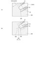
図28(A)において、工具3の影281に対して中心軸線284を検出したら、中心軸線284の両側に、所定距離Ofsをおいて、中心軸線284と平行な一対の平行線M,Mbを設定する。ここで、所定距離Ofsは、一対の平行線Ma,Mbと輪郭282との交点Ca,Cbが、輪郭282のボケが生じていない部分を通るように設定する。所定距離Ofsは、輪郭282の状態を見て調整してもよいが、工具3の刃先3Tの設計寸法に基づいて設定してもよい。
図28(B)において、一対の平行線Ma,Mbと輪郭282との交点Ca,Cbが得られたら、一対の交点Ca,Cbを通りかつ中心軸線284と直交する補助輪郭285を設定し、中心軸線284と補助輪郭285との交点を工具3の先端位置283として検出する。
In FIG. 28A, when the
In FIG. 28B, when the intersections Ca and Cb of the pair of parallel lines Ma and Mb and the
本実施形態では、補助輪郭285を設定することで、例えば一対の刃先3Tなど、先端に複数の突起をもつ工具3や、偏った先端をもつ工具3など、回転した状態では先端部の輪郭282の形状が不明瞭になる工具3についても、中心軸線284と補助輪郭285との交点により工具3の先端位置283を確定できる。これにより、多様な先端形状の工具3に対しても、単純な計算で工具3の先端位置283ないし回転軸(A軸あるいはC軸)の中心位置を高精度に計測できる。
In the present embodiment, by setting the
〔他の実施形態〕
なお、本発明は前述した実施形態に限定されるものではなく、本発明の目的を達成できる範囲での変形などは本発明に含まれる。
前記各実施形態では、5軸制御の工作機械1,1AのC軸あるいはA軸の回転中心位置を計測したが、本発明を適用する工作機械および軸は任意に選択できる。
例えば、工作機械としては回転軸としてA軸およびB軸を有する5軸制御であってもよく、そのB軸の回転中心位置を計測してもよい。また、工作機械は4軸制御あるいは6軸制御などであってもよく、少なくとも回転軸中心位置が問題となる回転軸を有するものであればよい。
[Other embodiments]
The present invention is not limited to the above-described embodiment, and modifications to the extent that the object of the present invention can be achieved are included in the present invention.
In each of the above embodiments, the rotation center positions of the C-axis or the A-axis of the 5-axis controlled
For example, the machine tool may be a 5-axis control having an A-axis and a B-axis as rotation axes, or the rotation center position of the B-axis may be measured. Further, the machine tool may be 4-axis control or 6-axis control, and may have at least a rotation axis at which the center position of the rotation axis becomes a problem.
前記実施形態では、工具3の先端位置を検出するために検出ユニット20,20Aを用いたが、検出ユニット20,20Aとしては平行光束28を形成するものに限らず、レーザ光ビームを平行に振って対象物を走査するもの(擬似的に平行光束となる)を用いてもよい。さらに、工具3に対して非接触であればよく、他の検出方式であってもよい。
In the above embodiment, the
本発明は、工作機械の回転軸中心位置計測方法に利用できる。 INDUSTRIAL APPLICABILITY The present invention can be used as a method for measuring the center position of a rotating shaft of a machine tool.
1,1A…工作機械、2…ワーク、3…工具、3T…刃先、9…制御装置、91…動作制御部、92…工具位置検出部、11…ベッド、12…移動テーブル、13…回転テーブル、131…クレードル、132…トラニオン、14…コラム、15…サドル、16…スライダ、17…主軸ヘッド、171…回転軸、18…主軸、20,20A…検出ユニット、21…ケース、22…固定手段を含む脚部、23…開口部、24…照明部、25…テレセントリックレンズ、26…撮像部であるCCDカメラ、261~265…検出画像、27…演算部、28…平行光束、281…影、282…輪郭、283…先端位置、284…中心軸線、285…補助輪郭線、29…検出対象物、31,32…交点、33…中点、A0~A270,An…角度位置、Ca,Cb…交点、Cc…周方向位置、D…距離、D1…第1方向、D2…第2方向、dc0…ずれ量、Dy…Y軸方向の成分、Dz…Z軸方向の成分、L01,L02…線分、L1…第1直線、L130…基準線、L2…第2直線、LA…線分、Ln…基準線、Ma,Mb…平行線、Ofs…所定間隔、P0~P270…工具先端位置、PA0,PA180…平面位置、PAc…中点、PBc…中心点、Pc…交点、Q0~Q180,Qn…A軸中心位置、QC…点列、QCc…中心点、Rc…径方向位置、Th,Tv…先端位置の座標、Tx0~Tx270…X軸座標、Ty0~Ty270…Y軸座標、Y1,Y2…Y軸位置、Z1,Z2…Z軸位置、θ,θn…角度。 1,1A ... Machine, 2 ... Work, 3 ... Tool, 3T ... Cutting edge, 9 ... Control device, 91 ... Motion control unit, 92 ... Tool position detection unit, 11 ... Bed, 12 ... Moving table, 13 ... Rotating table , 131 ... Cradle, 132 ... Tranion, 14 ... Column, 15 ... Saddle, 16 ... Slider, 17 ... Main shaft head, 171 ... Rotating shaft, 18 ... Main shaft, 20, 20A ... Detection unit, 21 ... Case, 22 ... Fixing means 23 ... opening, 24 ... lighting unit, 25 ... telecentric lens, 26 ... CCD camera which is an imaging unit, 261 to 265 ... detected image, 27 ... arithmetic unit, 28 ... parallel light beam, 281 ... shadow, 282 ... contour, 283 ... tip position, 284 ... central axis, 285 ... auxiliary contour line, 29 ... detection target, 31, 32 ... intersection, 33 ... middle point, A0 to A270, An ... angular position, Ca, Cb ... Intersection point, Cc ... Circumferential position, D ... Distance, D1 ... First direction, D2 ... Second direction, dc0 ... Deviation amount, Dy ... Y-axis direction component, Dz ... Z-axis direction component, L01, L02 ... Line Minutes, L1 ... 1st straight line, L130 ... reference line, L2 ... 2nd straight line, LA ... line segment, Ln ... reference line, Ma, Mb ... parallel lines, Ofs ... predetermined intervals, P0 to P270 ... tool tip position, PA0 , PA180 ... plane position, PAc ... middle point, PBc ... center point, Pc ... intersection point, Q0 to Q180, Qn ... A-axis center position, QC ... point sequence, QCc ... center point, Rc ... radial position, Th, Tv ... Coordinates of tip position, Tx0 to Tx270 ... X-axis coordinates, Ty0 to Ty270 ... Y-axis coordinates, Y1, Y2 ... Y-axis position, Z1, Z2 ... Z-axis position, θ, θn ... Angle.
Claims (11)
計測対象の回転軸について前記工具と前記テーブルとを所定の角度位置に割り出し、各角度位置で前記検出ユニットを用いて前記テーブルに対する前記工具の位置を検出する検出動作を繰り返し、
複数回の前記検出動作で検出された各角度位置での前記工具の位置から前記回転軸の中心位置を計算することを特徴とする工作機械の回転軸中心位置計測方法。 A tool is attached to the spindle, and a detection unit that can detect the position of the tool in a non-contact manner is installed on the table.
With respect to the rotation axis to be measured, the tool and the table are determined at predetermined angle positions, and the detection operation of detecting the position of the tool with respect to the table using the detection unit at each angle position is repeated.
A method for measuring the center position of a rotation axis of a machine tool, which calculates the center position of the rotation axis from the position of the tool at each angle position detected by the detection operation a plurality of times.
前記検出ユニットは、前記工具の先端が前記検出ユニットにおける特定位置にあることを非接触で検出可能であり、
前記検出動作では、前記主軸と前記テーブルとを相対移動させて前記工具と前記テーブルとを所定の角度位置に割り出し、前記各角度位置で前記工具が前記検出ユニットの前記特定位置にくるように前記主軸と前記テーブルとの相対位置を調節し、この状態で前記主軸と前記テーブルとの相対位置から前記各角度位置での前記テーブルに対する前記工具の位置を検出することを特徴とする工作機械の回転軸中心位置計測方法。 In the method for measuring the center position of the rotation axis of a machine tool according to claim 1,
The detection unit can non-contactly detect that the tip of the tool is at a specific position in the detection unit.
In the detection operation, the spindle and the table are relatively moved to determine the tool and the table at predetermined angle positions, and the tool is brought to the specific position of the detection unit at each angle position. Rotation of a machine tool, characterized in that the relative position of the spindle and the table is adjusted, and in this state, the position of the tool with respect to the table at each angle position is detected from the relative position of the spindle and the table. Axis center position measurement method.
前記工具の前記テーブルの径方向の位置を検出可能な前記検出ユニットを用い、
前記工具と前記テーブルとを、前記回転軸を挟んで第1方向に対向する2つの角度位置、および前記回転軸を挟んで前記第1方向と交差する第2方向に対向する2つの角度位置の4つの角度位置に割り出し、各角度位置で前記検出動作を行って前記工具の前記テーブルの径方向の位置を検出し、
前記第1方向に対向する2つの角度位置で検出された前記工具の位置を結ぶ線分の中点を通りかつ前記第1方向に交差する第1直線と、前記第2方向に対向する2つの角度位置で検出された前記工具の位置を結ぶ線分の中点を通りかつ前記第2方向に交差する第2直線とを計算し、前記第1直線と前記第2直線との交点を前記回転軸の中心位置として計測することを特徴とする工作機械の回転軸中心位置計測方法。 In the method for measuring the center position of a rotating shaft of a machine tool according to claim 1 or 2.
Using the detection unit capable of detecting the radial position of the table of the tool,
The tool and the table are at two angular positions facing the first direction across the rotation axis and two angular positions facing the first direction across the rotation axis. It is indexed to four angle positions, and the detection operation is performed at each angle position to detect the radial position of the table of the tool.
A first straight line that passes through the midpoint of the line segment connecting the positions of the tools detected at the two angular positions facing the first direction and intersects the first direction, and two facing the second direction. A second straight line that passes through the midpoint of the line segment connecting the positions of the tools detected at the angular position and intersects in the second direction is calculated, and the intersection of the first straight line and the second straight line is rotated. A method for measuring the center position of a rotating shaft of a machine tool, which is characterized by measuring as the center position of the shaft.
前記工具の前記テーブルの表面に沿った位置を検出可能な前記検出ユニットを用い、
前記工具と前記テーブルとを、前記回転軸を挟んで対向する2つの角度位置に割り出し、各角度位置で前記検出動作を行って前記工具の前記テーブルの表面に沿った位置を検出し、
2回の前記検出動作での前記工具の位置を結ぶ線分の中点を計算し、前記中点を前記回転軸の中心位置として計測することを特徴とする工作機械の回転軸中心位置計測方法。 In the method for measuring the center position of a rotating shaft of a machine tool according to claim 1 or 2.
Using the detection unit capable of detecting the position of the tool along the surface of the table,
The tool and the table are indexed at two angle positions facing each other across the rotation axis, and the detection operation is performed at each angle position to detect the position of the tool along the surface of the table.
A method for measuring the center position of a machine tool, which comprises calculating the midpoint of a line segment connecting the positions of the tools in the two detection operations and measuring the midpoint as the center position of the rotation axis. ..
前記工具の前記テーブルの径方向の位置を検出可能な前記検出ユニットを用い、
前記工具と前記テーブルとを、前記回転軸を中心とした所定角度範囲内の複数の角度位置に割り出し、各角度位置で前記検出動作を行って前記工具の前記テーブルの径方向の位置を検出し、
複数回の前記検出動作で得られた前記工具の位置をプロットし、近似計算により前記回転軸の中心位置を計算することを特徴とする工作機械の回転軸中心位置計測方法。 In the method for measuring the center position of a rotating shaft of a machine tool according to claim 1 or 2.
Using the detection unit capable of detecting the radial position of the table of the tool,
The tool and the table are indexed to a plurality of angular positions within a predetermined angle range about the rotation axis, and the detection operation is performed at each angle position to detect the radial position of the table of the tool. ,
A method for measuring the center position of a rotation axis of a machine tool, which comprises plotting the positions of the tools obtained by the detection operations a plurality of times and calculating the center position of the rotation axis by approximate calculation.
前記検出ユニットは、前記テーブルに対する固定手段を有することを特徴とする工作機械の回転軸中心位置計測方法。 In the method for measuring the center position of a rotating shaft of a machine tool according to any one of claims 1 to 5.
A method for measuring the center position of a rotation axis of a machine tool, wherein the detection unit has a fixing means to the table.
前記検出ユニットは、平行光束を照射する照明部と、前記平行光束を検出する撮像部と、を有し、
前記撮像部で検出された画像から前記平行光束中に配置された前記工具の先端位置を検出することを特徴とする工作機械の回転軸中心位置計測方法。 In the method for measuring the center position of a rotating shaft of a machine tool according to any one of claims 1 to 6.
The detection unit has an illumination unit that irradiates a parallel light flux and an image pickup unit that detects the parallel light flux.
A method for measuring the center position of a rotation axis of a machine tool, which comprises detecting the tip position of the tool arranged in the parallel luminous flux from an image detected by the image pickup unit.
前記工具を前記撮像部に対して回転した状態で、前記撮像部で前記画像を検出し、
前記画像から前記工具の輪郭を検出し、前記輪郭の対称性から前記工具の中心軸線を検出し、
前記中心軸線と前記輪郭との交点を前記工具の先端位置として検出することを特徴とする工作機械の回転軸中心位置計測方法。 In the method for measuring the center position of the rotation axis of a machine tool according to claim 7.
With the tool rotated with respect to the image pickup unit, the image pickup unit detects the image.
The contour of the tool is detected from the image, and the central axis of the tool is detected from the symmetry of the contour.
A method for measuring the center position of a rotation axis of a machine tool, which comprises detecting the intersection of the center axis and the contour as the tip position of the tool.
前記中心軸線と前記輪郭との交点を前記工具の先端位置として検出する際に、
前記中心軸線の両側に所定距離をおいて一対の平行線を設定し、一対の前記平行線と前記輪郭との交点を通りかつ前記中心軸線と直交する補助輪郭線を設定し、
前記中心軸線と前記補助輪郭線との交点を前記工具の先端位置として検出することを特徴とする工作機械の回転軸中心位置計測方法。 In the method for measuring the center position of the rotation axis of a machine tool according to claim 8.
When detecting the intersection of the central axis and the contour as the tip position of the tool,
A pair of parallel lines are set on both sides of the central axis at a predetermined distance, and an auxiliary contour line that passes through the intersection of the pair of parallel lines and the contour and is orthogonal to the central axis is set.
A method for measuring the center position of a rotating shaft of a machine tool, characterized in that the intersection of the center axis and the auxiliary contour line is detected as the tip position of the tool.
前記工具の延伸方向に前記輪郭を横断する複数の横断線を設定し、各々の前記横断線について前記輪郭との2つの交点および2つの前記交点の中点を検出し、各々の前記横断線の前記中点を通る直線を前記工具の中心軸線とすることを特徴とする工作機械の回転軸中心位置計測方法。 In the method for measuring the center position of a rotating shaft of a machine tool according to claim 8 or 9.
A plurality of transversals crossing the contour are set in the extending direction of the tool, two intersections with the contour and the midpoint of the two intersections are detected for each of the crossing lines, and each of the crossing lines A method for measuring the center position of a rotating shaft of a machine tool, wherein a straight line passing through the midpoint is set as the center axis of the tool.
前記工具の延伸方向に対して前記輪郭の片側の形状を基準パターンとして検出し、前記基準パターンを反転した形状に合致する対称パターンを前記輪郭から検出し、前記基準パターンと前記対称パターンとの中間を通る直線を前記工具の中心軸線とすることを特徴とする工作機械の回転軸中心位置計測方法。 In the method for measuring the center position of a rotating shaft of a machine tool according to claim 8 or 9.
The shape of one side of the contour with respect to the stretching direction of the tool is detected as a reference pattern, a symmetric pattern matching the shape obtained by inverting the reference pattern is detected from the contour, and an intermediate between the reference pattern and the symmetric pattern is detected. A method for measuring the center position of a rotation axis of a machine tool, wherein a straight line passing through the tool is used as the center axis of the tool.
Priority Applications (5)
| Application Number | Priority Date | Filing Date | Title |
|---|---|---|---|
| CN202180046712.5A CN115735094A (en) | 2020-06-26 | 2021-06-15 | Method for measuring center position of rotating shaft of machine tool |
| KR1020237000876A KR102745284B1 (en) | 2020-06-26 | 2021-06-15 | Method for measuring the center position of a rotary axis of a machine tool |
| PCT/JP2021/022651 WO2021261328A1 (en) | 2020-06-26 | 2021-06-15 | Method for measuring rotary axis center position of machine tool |
| DE112021003435.9T DE112021003435T5 (en) | 2020-06-26 | 2021-06-15 | Method of measuring a rotary axis center position of a machine tool |
| TW110122872A TWI769869B (en) | 2020-06-26 | 2021-06-23 | Method for measuring the center position of the rotating shaft of a machine tool |
Applications Claiming Priority (2)
| Application Number | Priority Date | Filing Date | Title |
|---|---|---|---|
| JP2020110638 | 2020-06-26 | ||
| JP2020110638 | 2020-06-26 |
Publications (2)
| Publication Number | Publication Date |
|---|---|
| JP2022008099A true JP2022008099A (en) | 2022-01-13 |
| JP7472079B2 JP7472079B2 (en) | 2024-04-22 |
Family
ID=80110446
Family Applications (1)
| Application Number | Title | Priority Date | Filing Date |
|---|---|---|---|
| JP2021085332A Active JP7472079B2 (en) | 2020-06-26 | 2021-05-20 | Method for measuring the center position of the rotating shaft of a machine tool |
Country Status (1)
| Country | Link |
|---|---|
| JP (1) | JP7472079B2 (en) |
Cited By (1)
| Publication number | Priority date | Publication date | Assignee | Title |
|---|---|---|---|---|
| WO2025074821A1 (en) * | 2023-10-06 | 2025-04-10 | 芝浦機械株式会社 | Measurement device, processing machine, program, and method for manufacturing object to be cut |
Citations (5)
| Publication number | Priority date | Publication date | Assignee | Title |
|---|---|---|---|---|
| JP2001259966A (en) * | 2000-03-15 | 2001-09-25 | Toyoda Mach Works Ltd | Method and device for correction of tool position |
| US20110213490A1 (en) * | 2010-02-26 | 2011-09-01 | National Formosa University | Method of detecting a dynamic path of a five-axis machine tool and detecting assembly for the same |
| JP2012093262A (en) * | 2010-10-27 | 2012-05-17 | Makino Milling Mach Co Ltd | Method and device for measuring tool dimensions, and machine tool |
| JP2016206120A (en) * | 2015-04-28 | 2016-12-08 | コニカミノルタ株式会社 | On-machine measurement method for tool |
| JP2019152574A (en) * | 2018-03-05 | 2019-09-12 | オークマ株式会社 | Method for measuring center position of rotation axis in machine tool |
-
2021
- 2021-05-20 JP JP2021085332A patent/JP7472079B2/en active Active
Patent Citations (5)
| Publication number | Priority date | Publication date | Assignee | Title |
|---|---|---|---|---|
| JP2001259966A (en) * | 2000-03-15 | 2001-09-25 | Toyoda Mach Works Ltd | Method and device for correction of tool position |
| US20110213490A1 (en) * | 2010-02-26 | 2011-09-01 | National Formosa University | Method of detecting a dynamic path of a five-axis machine tool and detecting assembly for the same |
| JP2012093262A (en) * | 2010-10-27 | 2012-05-17 | Makino Milling Mach Co Ltd | Method and device for measuring tool dimensions, and machine tool |
| JP2016206120A (en) * | 2015-04-28 | 2016-12-08 | コニカミノルタ株式会社 | On-machine measurement method for tool |
| JP2019152574A (en) * | 2018-03-05 | 2019-09-12 | オークマ株式会社 | Method for measuring center position of rotation axis in machine tool |
Non-Patent Citations (1)
| Title |
|---|
| 乾裕貴, 茨木創一, 洪策符, 下池昌広, 西川静雄: "主軸回転による熱変形を考慮した5軸加工機の幾何誤差キャリブレーション法", 精密工学会学術講演会講演論文集, vol. 2017年度精密工学会春季大会, JPN6024001553, 1 March 2017 (2017-03-01), JP, pages 203 - 204, ISSN: 0005243288 * |
Cited By (1)
| Publication number | Priority date | Publication date | Assignee | Title |
|---|---|---|---|---|
| WO2025074821A1 (en) * | 2023-10-06 | 2025-04-10 | 芝浦機械株式会社 | Measurement device, processing machine, program, and method for manufacturing object to be cut |
Also Published As
| Publication number | Publication date |
|---|---|
| JP7472079B2 (en) | 2024-04-22 |
Similar Documents
| Publication | Publication Date | Title |
|---|---|---|
| US10751883B2 (en) | Robot system with supplementary metrology position coordinates determination system | |
| CN113758421B (en) | Coordinate measuring machine | |
| CN105823435B (en) | A kind of gear measurement device and gear measuring method based on laser displacement sensor | |
| JP3021815B2 (en) | Method for measuring the surface of an object in a non-contact manner and a coordinate measuring machine for implementing the method | |
| CN109596073A (en) | A kind of origin position scaling method of the revolving platform central axis of view-based access control model measurement | |
| CN108908337B (en) | Measuring device and method for repetitive positioning accuracy of manipulator based on digital speckle interferometry | |
| CN108620955A (en) | Machine tool rotary axis error based on monocular vision measures and discrimination method | |
| KR102745284B1 (en) | Method for measuring the center position of a rotary axis of a machine tool | |
| CN108827187A (en) | A kind of measuring system for workpiece progress measuring three-dimensional profile | |
| TWM516714U (en) | Angular error correction device for machine tools | |
| JP2017150993A (en) | Inner wall measuring apparatus and offset amount calculating method | |
| TWI592252B (en) | Angular error correction device and method for machine tools | |
| CN105716547A (en) | Rapid measurement device and method for planeness of mechanical workpiece | |
| CN106737194B (en) | In-situ detection method and device for airbag contour | |
| TWI754563B (en) | Spatial accuracy error measurement method | |
| CN111408861A (en) | Five-axis laser equipment RTCP calibration equipment and method | |
| JP2022008099A (en) | Rotation axis center position measuring method of machine tool | |
| CN116481470B (en) | A method for measuring the coordinates of the rotation center of a visual coordinate measuring device | |
| JP2014081279A (en) | Three-dimensional shape measuring apparatus and three-dimensional shape measuring method | |
| CN114018174B (en) | Complex Surface Profile Measurement System | |
| CN113639633B (en) | Clamp angular zero alignment method in multi-axis vision measurement device | |
| JP6946584B1 (en) | Image processing equipment and machine tools | |
| CN116499356B (en) | Method for establishing a reference coordinate system based on a target device used as a reference | |
| JP2003121134A (en) | How to measure motion accuracy | |
| CN116358467B (en) | A method for determining the position of the rotation axis using an absolute position target |
Legal Events
| Date | Code | Title | Description |
|---|---|---|---|
| A621 | Written request for application examination |
Free format text: JAPANESE INTERMEDIATE CODE: A621 Effective date: 20221213 |
|
| A131 | Notification of reasons for refusal |
Free format text: JAPANESE INTERMEDIATE CODE: A131 Effective date: 20240123 |
|
| A521 | Request for written amendment filed |
Free format text: JAPANESE INTERMEDIATE CODE: A523 Effective date: 20240305 |
|
| TRDD | Decision of grant or rejection written | ||
| A01 | Written decision to grant a patent or to grant a registration (utility model) |
Free format text: JAPANESE INTERMEDIATE CODE: A01 Effective date: 20240319 |
|
| A61 | First payment of annual fees (during grant procedure) |
Free format text: JAPANESE INTERMEDIATE CODE: A61 Effective date: 20240410 |
|
| R150 | Certificate of patent or registration of utility model |
Ref document number: 7472079 Country of ref document: JP Free format text: JAPANESE INTERMEDIATE CODE: R150 |