JP2022010902A - Pressure resistant bottle - Google Patents
Pressure resistant bottle Download PDFInfo
- Publication number
- JP2022010902A JP2022010902A JP2020111687A JP2020111687A JP2022010902A JP 2022010902 A JP2022010902 A JP 2022010902A JP 2020111687 A JP2020111687 A JP 2020111687A JP 2020111687 A JP2020111687 A JP 2020111687A JP 2022010902 A JP2022010902 A JP 2022010902A
- Authority
- JP
- Japan
- Prior art keywords
- circumferential direction
- ground contact
- outer peripheral
- bottle
- wall portion
- Prior art date
- Legal status (The legal status is an assumption and is not a legal conclusion. Google has not performed a legal analysis and makes no representation as to the accuracy of the status listed.)
- Granted
Links
- 230000002093 peripheral effect Effects 0.000 claims abstract description 72
- 239000000463 material Substances 0.000 claims description 15
- 229920003002 synthetic resin Polymers 0.000 claims description 5
- 239000000057 synthetic resin Substances 0.000 claims description 5
- 238000000465 moulding Methods 0.000 description 9
- 229920005989 resin Polymers 0.000 description 8
- 239000011347 resin Substances 0.000 description 8
- 239000010410 layer Substances 0.000 description 7
- 238000000071 blow moulding Methods 0.000 description 5
- 230000007547 defect Effects 0.000 description 2
- 238000010438 heat treatment Methods 0.000 description 2
- 230000004048 modification Effects 0.000 description 2
- 238000012986 modification Methods 0.000 description 2
- -1 polyethylene terephthalate Polymers 0.000 description 2
- 235000002597 Solanum melongena Nutrition 0.000 description 1
- 244000061458 Solanum melongena Species 0.000 description 1
- 238000010521 absorption reaction Methods 0.000 description 1
- QVGXLLKOCUKJST-UHFFFAOYSA-N atomic oxygen Chemical compound [O] QVGXLLKOCUKJST-UHFFFAOYSA-N 0.000 description 1
- 230000004888 barrier function Effects 0.000 description 1
- 238000005452 bending Methods 0.000 description 1
- 235000014171 carbonated beverage Nutrition 0.000 description 1
- 230000008602 contraction Effects 0.000 description 1
- 239000007789 gas Substances 0.000 description 1
- 230000012447 hatching Effects 0.000 description 1
- 230000001771 impaired effect Effects 0.000 description 1
- 239000007788 liquid Substances 0.000 description 1
- 239000000203 mixture Substances 0.000 description 1
- 229910052760 oxygen Inorganic materials 0.000 description 1
- 239000001301 oxygen Substances 0.000 description 1
- 229920003207 poly(ethylene-2,6-naphthalate) Polymers 0.000 description 1
- 229920000728 polyester Polymers 0.000 description 1
- 239000011112 polyethylene naphthalate Substances 0.000 description 1
- 229920000139 polyethylene terephthalate Polymers 0.000 description 1
- 239000005020 polyethylene terephthalate Substances 0.000 description 1
- 230000000630 rising effect Effects 0.000 description 1
- 239000002356 single layer Substances 0.000 description 1
- 238000007740 vapor deposition Methods 0.000 description 1
- 239000013585 weight reducing agent Substances 0.000 description 1
Images
Landscapes
- Containers Having Bodies Formed In One Piece (AREA)
Abstract
Description
本発明は、耐圧ボトルに関する。 The present invention relates to a pressure resistant bottle.
従来から、例えば下記特許文献1に示されるように、口部、肩部、胴部、および底部が、ボトル軸方向に沿って上方から下方に向けてこの順に連設されるとともに、合成樹脂材料で一体に形成され、底部は、ボトル軸上に位置する中央壁部と、中央壁部の外周縁と胴部とを連結する連結周壁部と、を備え、連結周壁部に、周方向に間隔をあけて3つ以上の縦溝部が形成され、連結周壁部において周方向に隣り合う縦溝部同士の間に位置する各部分に、中央壁部よりも下方に向けて突出した脚部が形成された耐圧ボトルが知られている。
Conventionally, for example, as shown in
耐圧ボトルにおいては、近年の軽量化、および充填される内容液の強炭酸化等の要請もあり、内圧の上昇時に、例えば中央壁部を下方に向けて膨出変形しにくくする等、底部の耐圧性を向上させることに対する要望が高まっている。 In the case of pressure-resistant bottles, there is a recent demand for weight reduction and strong carbonation of the filling liquid, and when the internal pressure rises, for example, the central wall part is made to bulge downward to make it difficult to deform. There is a growing demand for improved pressure resistance.
本発明は、前述した事情に鑑みてなされたものであって、底部の耐圧性を向上させることができる耐圧ボトルを提供することを目的とする。 The present invention has been made in view of the above-mentioned circumstances, and an object of the present invention is to provide a pressure-resistant bottle capable of improving the pressure resistance of the bottom.
本発明は、上記課題を解決するために以下のような手段を採用した。すなわち、本発明の耐圧ボトルは、口部、肩部、胴部、および底部が、ボトル軸方向に沿って上方から下方に向けてこの順に連設されるとともに、合成樹脂材料で一体に形成され、前記底部は、ボトル軸上に位置する中央壁部と、前記中央壁部の外周縁と前記胴部とを連結する連結周壁部と、を備え、前記連結周壁部に、周方向に間隔をあけて3つ以上の縦溝部が形成され、前記連結周壁部において周方向に隣り合う前記縦溝部同士の間に位置する各部分に、前記中央壁部よりも下側に向けて突出した脚部が形成され、前記脚部の下端部に、周方向に延びる接地部が形成され、前記底部を下方から見て、前記接地部の外周縁は、径方向の外側に向けて突の曲線状を呈するとともに、複数の前記接地部の外周縁における周方向の各中央部は、ボトル軸を中心とする同一の円上に位置し、前記接地部の外周縁は、周方向の中央部から周方向に離れるに従い、前記円から径方向の内側に離れている。 The present invention employs the following means to solve the above problems. That is, in the pressure-resistant bottle of the present invention, the mouth, shoulder, body, and bottom are connected in this order from upper to lower along the bottle axis direction, and are integrally formed of a synthetic resin material. The bottom portion includes a central wall portion located on the bottle axis and a connecting peripheral wall portion connecting the outer peripheral edge of the central wall portion and the body portion, and the connecting peripheral wall portion is spaced apart in the circumferential direction. Three or more vertical grooves are formed by opening, and the legs protruding downward from the central wall in each portion located between the vertical grooves adjacent to each other in the circumferential direction in the connecting peripheral wall portion. Is formed, and a ground contact portion extending in the circumferential direction is formed at the lower end portion of the leg portion. In addition, each central portion in the circumferential direction on the outer peripheral edge of the plurality of ground contact portions is located on the same circle centered on the bottle axis, and the outer peripheral edge of the ground contact portion is circumferentially from the central portion in the circumferential direction. As the distance from the circle increases, the distance from the circle increases inward in the radial direction.
本発明によれば、底部を下方から見て(以下、底面視という)、接地部の外周縁が、径方向の外側に向けて突の曲線状を呈するとともに、複数の接地部の外周縁における周方向の各中央部が、ボトル軸を中心とする同一の円上に位置し、接地部の外周縁が、周方向の中央部から周方向に離れるに従い、前記円から径方向の内側に離れているので、接地部の外周縁における周方向の端部が、周方向に張り出すのを抑制することができる。
これにより、底部の表面積を抑えて底部の肉厚を確保することが可能になり、底部の耐圧性を向上することができる。
また、このように周方向の張り出しが抑えられることから、ブロー成形時に、成形金型のキャビティのうち、接地部の周方向の端部を成形する部分(以下、端成形部という)を流動する樹脂材料が、過度に延伸することが抑えられることとなり、ボイドが発生するのを抑制しつつ、前記端成形部に樹脂材料が行き渡りにくくなるのを抑制することが可能になり、賦形性を向上させることができる。
これにより、成形温度(プリフォームの加熱温度)を低く抑えたり、接地部の外周縁の直径を大きくしたりしても、ブロー成形時に、前記端成形部に樹脂材料が行き渡りにくくなるのを抑制することができる。したがって、成形不良の発生を抑えつつ、耐圧性を確実に向上することができるとともに、前述したように周方向の張り出しが抑えられていても、接地部の外周縁の周方向の長さを長く確保して、転倒角を大きく確保することができる。
According to the present invention, when the bottom portion is viewed from below (hereinafter referred to as bottom view), the outer peripheral edge of the ground contact portion exhibits a curved shape of a protrusion toward the outside in the radial direction, and at the outer peripheral edge of the plurality of ground contact portions. Each central portion in the circumferential direction is located on the same circle centered on the bottle axis, and the outer peripheral edge of the ground contact portion is separated from the central portion in the circumferential direction inward in the radial direction as the distance from the central portion in the circumferential direction increases in the circumferential direction. Therefore, it is possible to prevent the peripheral end portion of the outer peripheral edge of the ground contact portion from protruding in the circumferential direction.
As a result, it becomes possible to suppress the surface area of the bottom portion and secure the wall thickness of the bottom portion, and it is possible to improve the pressure resistance of the bottom portion.
Further, since the protrusion in the circumferential direction is suppressed in this way, the portion of the cavity of the molding die that forms the peripheral end portion of the ground contact portion (hereinafter referred to as the end molding portion) flows during blow molding. It is possible to suppress the resin material from being excessively stretched, and it is possible to suppress the generation of voids while suppressing the difficulty in distributing the resin material to the end molded portion, thereby improving the shapeability. Can be improved.
As a result, even if the molding temperature (heating temperature of the preform) is kept low or the diameter of the outer peripheral edge of the ground contact portion is increased, it is possible to prevent the resin material from being easily distributed to the end molded portion during blow molding. can do. Therefore, it is possible to surely improve the pressure resistance while suppressing the occurrence of molding defects, and even if the protrusion in the circumferential direction is suppressed as described above, the length of the outer peripheral edge of the ground contact portion in the circumferential direction is increased. It can be secured and a large tipping angle can be secured.
この発明によれば、底部の耐圧性を向上させることができる。 According to the present invention, the pressure resistance of the bottom can be improved.
以下、図面を参照し、本発明の一実施形態について説明する。
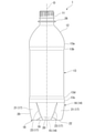
本実施形態に係る耐圧ボトル1は、図1に示されるように、口部11、肩部12、胴部13、および底部14が、ボトル軸O方向に沿って上方から下方に向けてこの順に連設されるとともに、合成樹脂材料で一体に形成されている。耐圧ボトル1は、例えば二軸延伸ブロー成形等により形成される。耐圧ボトル1には、密封された状態で内圧を上昇させる例えば炭酸飲料等が充填される。
Hereinafter, an embodiment of the present invention will be described with reference to the drawings.
In the pressure-
口部11、肩部12、胴部13および底部14はそれぞれ、円筒状に形成されるとともに、ボトル軸Oと同軸に配置されている。
以下、ボトル軸O方向から見て、ボトル軸Oに交差する方向を径方向といい、ボトル軸O周りに周回する方向を周方向という。
The
Hereinafter, the direction that intersects the bottle axis O when viewed from the bottle axis O direction is referred to as a radial direction, and the direction that orbits around the bottle axis O is referred to as a circumferential direction.
口部11の外面には、図示しないキャップが着脱可能に螺着される雄ねじ部が形成されている。口部11の外面において、雄ねじ部より下方に位置する部分に、周方向の全長にわたって連続して延びるネックリング26が設けられている。なお、ネックリング26を有しない耐圧ボトルを採用してもよい。
On the outer surface of the
肩部12は、上側から下側に向かうに従い、拡径している。肩部12の下端部は、胴部13の上端部に段差なく滑らかに連なっている。
胴部13の上端部は、肩部12の下端部から下方に真直ぐ延びる上直筒部13aと、上直筒部13aの下端部から下方に向かうに従い、径方向の内側に向けて延びる上縮径部13bと、を備えている。
The diameter of the
The upper end portion of the
底部14は、ボトル軸O上に位置する中央壁部15と、中央壁部15の外周縁と胴部13の下端部とを連結する連結周壁部16と、を備えている。連結周壁部16の上端部は、胴部13の下端部に段差なく滑らかに連なっている。
胴部13の下端部は、連結周壁部16の上端部から上方に真直ぐ延びる下直筒部13cと、下直筒部13cの上端部から上方に向かうに従い、径方向の内側に向けて延びる下縮径部13dと、を備えている。
The
The lower end of the
上直筒部13aおよび下直筒部13cが、この耐圧ボトル1において外径が最も大きい部分となっている。上直筒部13aおよび下直筒部13cの各外径は、例えば62.2mm以上70.5mm以下とされ、図示の例では約66mmとなっている。
耐圧ボトル1のボトル軸O方向の長さは、例えば198mm以上220mm以下とされ、図示の例では約206mmとなっている。耐圧ボトル1の内容量は、例えば400ml以上600ml以下とされ、図示の例では、耐圧ボトル1は500ml用となっている。
なお、以上の各数値は適宜変更してもよい。
The upper
The length of the pressure-
In addition, each of the above numerical values may be changed as appropriate.
中央壁部15は、ボトル軸Oと同軸に配置された円板状に形成されている。中央壁部15は平坦に形成されている。なお、中央壁部15は、下方または上方に向けて突の曲面状に形成されてもよい。
連結周壁部16に、周方向に間隔をあけて3つ以上の縦溝部17が形成されている。連結周壁部16において周方向に隣り合う縦溝部17同士の間に位置する各部分に、中央壁部15よりも下側に向けて突出した脚部18が形成されている。縦溝部17および脚部18はそれぞれ、連結周壁部16に奇数個ずつ形成され、図示の例では5個ずつ形成されている。複数の縦溝部17は、互いに同じ形状および大きさで形成され、周方向に同等の間隔をあけて配置されている。複数の脚部18は、互いに同じ形状および大きさで形成され、周方向に同等の間隔をあけて配置されている。底部14は、いわゆるペタロイド形状に形成されている。
なお、縦溝部17および脚部18はそれぞれ、連結周壁部16に偶数個ずつ形成されてもよい。
The
Three or more
In addition, an even number of the
脚部18は、接地部22と、接地部22から上方に向けて延び、胴部13の下端部に連結された外壁部20と、接地部22から径方向の内側に向けて延び、中央壁部15の外周縁に連結された内壁部19と、を備えている。
The
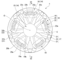
接地部22は、脚部18の下端部に形成されている。接地部22は、中央壁部15より下方に位置している。接地部22は、中央壁部15から下方に例えば4mm以上6mm以下離れ、図示の例では約5mm離れている。なお、この数値は適宜変更してもよい。接地部22は、図2にハッチングで示されるように、周方向の全長にわたって間欠的に配置されている。接地部22は、径方向の大きさを有する面状に形成されている。接地部22は、ボトル軸O方向を向く平坦面となっている。なお、接地部22は、径方向の大きさが極めて小さい線状に形成されてもよい。
The
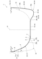
外壁部20の表裏面はそれぞれ、径方向を向いている。外壁部20は、上側から下側に向かうに従い、径方向の内側に向けて延びている。図3に示されるように、外壁部20において、接地部22に接地部22の径方向の外側から連なる下端部(以下、外連設部という)20aは、ボトル軸Oに沿う縦断面視において、径方向の外側に向けて突となる曲線状をなすように湾曲している。前記縦断面視で外連設部20aの曲率半径は、例えば12mm以上25mm以下とされ、図示の例では約18mmとなっている。なお、この数値は適宜変更してもよい。
The front and back surfaces of the
外壁部20のうち、外連設部20aより上方に位置する部分(以下、上部分という)20bは、径方向の外側に向けて突の曲面状に形成されている。前記縦断面視で上部分20bの曲率半径は、外連設部20aの曲率半径より大きく、例えば86mm以上207mm以下とされ、図示の例では約150mmとなっている。なお、この数値は適宜変更してもよい。上部分20bは、胴部13の下端部、および外連設部20aの上端部と段差なく滑らかに連なっている。
Of the
内壁部19の表裏面はそれぞれ、ボトル軸O方向を向いている。内壁部19は、接地部22から径方向の内側に向かうに従い、上方に向けて延びている。内壁部19において中央壁部15に連結された径方向の内端部は、中央壁部15と段差なく滑らかに連なっている。
内壁部19のうち、接地部22に径方向の内側から連なる部分(以下、内連設部という)19aは、ボトル軸O方向に沿う縦断面視において、下方に向けて突となる曲線状をなすように湾曲している。前記縦断面視において、内連設部19aの曲率半径は、例えば7mm以上12mm以下とされ、図示の例では約9mmとなっている。なお、この数値は適宜変更してもよい。
The front and back surfaces of the
Of the
内壁部19のうち、内連設部19aより径方向の内側に位置する部分(以下、内部分という)19bは、前記縦断面視において、上方に向けて突となる曲線状をなすように湾曲している。すなわち、前記縦断面視において、内連設部19aが突となる向きと、内部分19bが突となる向きと、が互いに逆向きになっている。前記縦断面視で、耐圧ボトル1の外面に沿う内部分19bの長さは、耐圧ボトル1の外面に沿う内連設部19aの長さより長く、内部分19bの曲率半径は、内連設部19aの曲率半径より大きくなっている。
内壁部19は、周方向の中央部から周方向に離れるに従い、下方に向けて延び、かつ上方に向けて突の曲面状に形成されている。
Of the
The
ここで、底部14は、接地部22、内壁部19および外壁部20それぞれにおける周方向の両端部を各別に一体に連結した一対の側壁部21を備えている。側壁部21の表裏面は周方向を向いている。
縦溝部17は、径方向の外側を向く溝底面23と、溝底面23における周方向の両端部から径方向の外側に向けて突出して周方向で互いに対向する側壁部21の表面と、により画成されている。
Here, the
The
図3に示されるように、溝底面23は、下方に向かうに従い、径方向の内側に向けて延びている。溝底面23は、胴部13から下方に向けて延びる上部31と、上部31から下方に向けて延び、中央壁部15の外周縁に連結された下部32と、を備えている。
As shown in FIG. 3, the
上部31は、上端部31aを除く全域にわたって、下方に向かうに従い、径方向の内側に向けて直線状に延びている。以下、上部31のうち、上端部31aより下方に位置する部分を直線部31bという。
上端部31aは、径方向の外側に向けて突の曲面状に形成されている。前記縦断面視において、上端部31aの曲率半径は、例えば約10mmとなっている。前記縦断面視において、耐圧ボトル1の外面に沿う上端部31aの長さ(符号A~B間)は、耐圧ボトル1の外面に沿う上部31の長さ(符号A~C間)の、例えば10%未満となっている。上端部31aは、胴部13の下端部に段差なく滑らかに連なっている。
直線部31bのボトル軸O方向に対する傾斜角度θは、例えば10°以上30°以下とされ、図示の例では約22°となっている。なお、この数値は適宜変更してもよい。
The
The
The inclination angle θ of the
前記縦断面視において、耐圧ボトル1の外面に沿う上部31の長さは、下部32と中央壁部15との接続部分Fと、ボトル軸Oと、の径方向の距離より長くなっている。図示の例では、耐圧ボトル1の外面に沿う直線部31bの長さも、前記接続部分Fとボトル軸Oとの径方向の距離より長くなっている。なお、耐圧ボトル1の外面に沿う直線部31bの長さを、前記接続部分Fとボトル軸Oとの径方向の距離以下としてもよい。
In the vertical cross-sectional view, the length of the
前記縦断面視において、耐圧ボトル1の外面に沿う上部31の長さは、耐圧ボトル1の外面に沿って、上部31の上端縁Aから下部32を介して、ボトル軸Oが位置する中央壁部15の中心に至るまでの長さの、例えば30%以上40%以下とされ、図示の例では約34%となっている。なお、この数値は適宜変更してもよい。
下部32と中央壁部15との接続部分Fと、ボトル軸Oと、の径方向の距離は、耐圧ボトル1の外面に沿って、上部31の上端縁Aから下部32を介して、中央壁部15の中心に至るまでの長さの、例えば15%以上25%以下とされ、図示の例では約21%となっている。なお、この数値は適宜変更してもよい。
In the vertical cross-sectional view, the length of the
The radial distance between the connecting portion F between the
下部32は、径方向の外側に向けて突の曲面状に形成されている。下部32は、上部31の下端縁、および中央壁部15の外周縁に段差なく滑らかに連なっている。下部32は、前記縦断面視で互いに曲率半径が異なる複数の円弧部分が連ねられて構成されている。図示の例では、前記縦断面視で、下部32のうち、下端部32aの曲率半径は、下端部32aより上方に位置する部分(以下、主部分という)32bの曲率半径より小さくなっている。前記縦断面視で、耐圧ボトル1の外面に沿う下部32の下端部32aの長さ(符号D~F間)は、耐圧ボトル1の外面に沿う下部32の主部分32bの長さ(符号C~D間)より短くなっている。前記縦断面視で、下部32の下端部32aの曲率半径は、例えば約16mmとされ、下部32の主部分32bの曲率半径は、例えば約21mmとなっている。
The
前記縦断面視において、耐圧ボトル1の外面に沿う下部32の長さ(符号C~F間)は、耐圧ボトル1の外面に沿う上部31の長さ以上となっている。耐圧ボトル1の外面に沿う下部32の長さは、前記縦断面視において、耐圧ボトル1の外面に沿って、上部31の上端縁Aから下部32を介して中央壁部15の中心に至るまでの長さの、例えば40%以上50%以下とされ、図示の例では約45%となっている。なお、この数値は適宜変更してもよい。耐圧ボトル1の外面に沿う下部32の長さを、耐圧ボトル1の外面に沿う上部31の長さより短くしてもよい。
In the vertical cross-sectional view, the length of the lower portion 32 (between reference numerals C and F) along the outer surface of the pressure
脚部18の内壁部19と中央壁部15との接続部分Eは、溝底面23の下部32と中央壁部15との接続部分Fより径方向の外側に位置している。前者の接続部分Eは、主部分32bの下端縁(符号D)より径方向の内側に位置している。前者の接続部分Eと後者の接続部分Fとの径方向の距離は、前者の接続部分Eと主部分32bの下端縁との径方向の距離より小さくなっている。なお、前者の接続部分Eと後者の接続部分Fとの径方向の距離を、前者の接続部分Eと主部分32bの下端縁との径方向の距離以上としてもよい。
The connecting portion E between the
そして、本実施形態では、図2に示されるように、底部14を下方から見た底面視において、接地部22の外周縁22aは、径方向の外側に向けて突の曲線状を呈するとともに、複数の接地部22の外周縁22aにおける周方向の各中央部が、ボトル軸Oを中心とする同一の円(以下、基準円Cという)上に位置し、接地部22の外周縁22aは、周方向の中央部から周方向に離れるに従い、基準円Cから径方向の内側に離れている。
Then, in the present embodiment, as shown in FIG. 2, when the
図示の例では、接地部22の外周縁22aは、前記底面視で単一の円弧形状を呈し、接地部22の外周縁22aの曲率半径は、ボトル軸Oと接地部22の外周縁22aにおける周方向の中央部との径方向の距離(以下、基準半径という)以下となっている。前記底面視において、接地部22の外周縁22aの曲率半径は、基準半径より小さくなっている。
なお、接地部22の外周縁22aは、前記底面視で互いに曲率半径が異なる複数の円弧部分が連ねられて構成されてもよい。
In the illustrated example, the outer
The outer
接地部22は、外周縁22aと、外周縁22aより径方向の内側に位置する内周縁22bと、外周縁22aおよび内周縁22bそれぞれの周方向の端部同士を連結する一対の周端縁22cと、により画成されている。
前記底面視において、接地部22の内周縁22bは、径方向の外側に向けて突の曲線状を呈するとともに、内周縁22bの曲率半径は、外周縁22aの曲率半径より大きくなっている。前記底面視において、接地部22の周端縁22cは、周方向の外側に向けて突の曲線状を呈する。接地部22の径方向の大きさは、接地部22における周方向の中央部から周方向に離れるに従い小さくなっている。
The grounding
In the bottom view, the inner peripheral edge 22b of the
以上説明したように、本実施形態による耐圧ボトル1によれば、前記底面視において、接地部22の外周縁22aが、径方向の外側に向けて突の曲線状を呈するとともに、複数の接地部22の外周縁22aにおける周方向の各中央部が、基準円C上に位置し、接地部22の外周縁22aが、周方向の中央部から周方向に離れるに従い、基準円Cから径方向の内側に離れているので、接地部22の外周縁22aにおける周方向の端部が、周方向に張り出すのを抑制することができる。
これにより、底部14の表面積を抑えて底部14の肉厚を確保することが可能になり、底部14の耐圧性を向上することができる。
As described above, according to the pressure-
As a result, the surface area of the
また、このように周方向の張り出しが抑えられることから、ブロー成形時に、成形金型のキャビティのうち、接地部22の周方向の端部を成形する部分(以下、端成形部という)を流動する樹脂材料が、過度に延伸することが抑えられることとなり、ボイドが発生するのを抑制しつつ、前記端成形部に樹脂材料が行き渡りにくくなるのを抑制することが可能になり、賦形性を向上させることができる。 Further, since the protrusion in the circumferential direction is suppressed in this way, the portion of the cavity of the molding die that forms the peripheral end portion of the ground contact portion 22 (hereinafter referred to as the end molding portion) flows during blow molding. It is possible to suppress excessive stretching of the resin material to be formed, and it is possible to suppress the generation of voids and to prevent the resin material from being easily distributed to the end molded portion. Can be improved.
これにより、成形温度(プリフォームの加熱温度)を低く抑えたり、接地部22の外周縁22aの直径を大きくしたりしても、ブロー成形時に、前記端成形部に樹脂材料が行き渡りにくくなるのを抑制することができる。したがって、成形不良の発生を抑えつつ、耐圧性を確実に向上することができるとともに、前述したように周方向の張り出しが抑えられていても、接地部22の外周縁22aの周方向の長さを長く確保して、転倒角を大きく確保することができる。
As a result, even if the molding temperature (heating temperature of the preform) is kept low or the diameter of the outer
溝底面23の上部31が、上端部31aを除く全域にわたって、下方に向かうに従い、径方向の内側に向けて直線状に延びているので、内圧の上昇時に、溝底面23の上部31が径方向の外側に向けて変形しやすくなり、内圧の上昇を抑えて中央壁部15に生ずる応力を緩和することができる。これにより、内圧の上昇時に、中央壁部15が下方に向けて膨出変形するのを抑制することができる。
Since the
溝底面23の下部32が、径方向の外側に向けて突の曲面状に形成され、前記縦断面視において、耐圧ボトル1の外面に沿う下部32の長さが、耐圧ボトル1の外面に沿う溝底面23の上部31の長さ以上となっているので、底部14内の面積を広く確保することが可能になり、内圧の上昇時に、溝底面23のうち、中央壁部15に連なる下部32ではなく上部31が、径方向の外側に向けて変形することと相俟って、中央壁部15に生ずる応力を確実に抑えることができる。
The
前記縦断面視において、耐圧ボトル1の外面に沿う上部31の長さが、耐圧ボトル1の外面に沿って、上部31の上端縁Aから下部32を介して、中央壁部15の中心に至るまでの長さの30%以上40%以下となっているので、内圧の上昇時に、下部32に上部31から加えられる負荷を抑えつつ、上部31を径方向の外側に向けて確実に変形させることができる。
30%未満になると、内圧の上昇時に、上部31を径方向の外側に向けて変形させにくくなるおそれがあり、40%を超えると、内圧の上昇時に、下部32に上部31から大きな負荷が加えられるおそれがある。
In the vertical cross-sectional view, the length of the
If it is less than 30%, it may be difficult to deform the
中央壁部15が、平坦な円板状に形成されているので、下方に向けて突の曲面状に形成されている場合と比べて、内圧の上昇時に、中央壁部15を下方に向けて膨出変形させにくくすることができる。
Since the
前記縦断面視において、耐圧ボトル1の外面に沿う上部31の長さが、下部32と中央壁部15との接続部分Fと、ボトル軸Oと、の径方向の距離より長くなっているので、中央壁部15のボトル軸O方向の曲げ剛性を確保しつつ、内圧の上昇時に、上部31を径方向の外側に向けて円滑に変形させることができる。
In the vertical cross-sectional view, the length of the
内壁部19と中央壁部15との接続部分E、および下部32と中央壁部15との接続部分Fそれぞれの径方向の位置が互いに異なっているので、これらの各接続部分E、Fの径方向の位置が互いに同じになっている場合と比べて、内圧の上昇時に、内壁部19および下部32と、中央壁部15と、の各接続部分E、Fに、周方向に延びる段部が発現しにくくなり、ひび割れが生ずるのを抑制することができる。
Since the radial positions of the connecting portion E between the
内壁部19と中央壁部15との接続部分Eが、下部32と中央壁部15との接続部分Fより径方向の外側に位置しているので、前者の接続部分Eが、後者の接続部分Fに対して、同じ径方向の位置に位置している場合、および径方向の内側に位置している場合と比べて、接地部22に対する内壁部19の立ち上がり角度を急峻にすることが可能になり、内圧の上昇時に、内壁部19が接地部22回りに下方に向けて倒れ込みにくくなり、接地安定性を具備させることができる。
Since the connection portion E between the
溝底面23の直線部31bのボトル軸O方向に対する傾斜角度θが、10°以上30°以下となっているので、接地安定性を阻害することなく、内圧の上昇時に、中央壁部15が下方に向けて膨出変形するのを抑制することができる。
前記傾斜角度θが10°未満になると、内圧の上昇時に、上部31が径方向の外側に向けて変形しにくくなり、中央壁部15に生ずる応力を緩和しにくくなるおそれがある。前記傾斜角度θが30°を超えると、接地部22とボトル軸Oとの径方向の距離が短くなり、接地安定性が阻害されるおそれがある。
Since the inclination angle θ of the
When the inclination angle θ is less than 10 °, when the internal pressure rises, the
なお、本発明の技術範囲は、前述した実施形態に限定されるものではなく、本発明の趣旨を逸脱しない範囲において種々の変更を加えることが可能である。 The technical scope of the present invention is not limited to the above-described embodiment, and various modifications can be made without departing from the spirit of the present invention.
例えば、前記実施形態では、接地部22として、径方向の大きさを有する面状の構成を示したが、径方向の大きさが極めて小さい線状の構成等を採用してもよい。
接地部22として、ボトル軸O方向を向く平坦面に形成された構成を示したが、前記底面視における接地部22の内側部分に、上方に向けて窪む凹部等を形成してもよい。
接地部22は、1つの脚部18において、例えば径方向、若しくは周方向等に分割されていてもよい。
接地部22の径方向の大きさは、接地部22における周方向の全域にわたって同等にしてもよい。
前記底面視において、接地部22の内周縁22bの曲率半径を、接地部22の外周縁22aの曲率半径以下としてもよい。
For example, in the above-described embodiment, the
Although the
The
The radial size of the
In the bottom view, the radius of curvature of the inner peripheral edge 22b of the
例えば、前記実施形態では、溝底面23の下部32として、前記縦断面視で互いに曲率半径が異なる複数の円弧部分が連ねられた構成を示したが、1つの円弧部分のみからなる構成を採用してもよい。
前記縦断面視において、耐圧ボトル1の外面に沿う溝底面23の上部31の長さを、溝底面23の下部32と中央壁部15との接続部分Fと、ボトル軸Oと、の径方向の距離以下としてもよい。
脚部18の内壁部19と中央壁部15との接続部分Eを、下部32と中央壁部15との接続部分Fに対して、同じ径方向の位置に位置させてもよいし、径方向の内側に位置させてもよい。
For example, in the above-described embodiment, the
In the vertical cross-sectional view, the length of the
The connecting portion E between the
また、耐圧ボトル1を形成する合成樹脂材料は、例えばポリエチレンテレフタレートや、ポリエチレンナフタレート、非晶性ポリエステル等、またはこれらのブレンド材料等、適宜変更してもよい。
さらに、耐圧ボトル1は、単層構造体に限らず中間層を有する積層構造体としてもよい。この中間層としては、例えばガスバリア性を有する樹脂材料からなる層、再生材からなる層、酸素吸収性を有する樹脂材料からなる層、若しくはこれらの層の組み合わせ、または蒸着層等が挙げられる。
Further, the synthetic resin material forming the pressure
Further, the pressure-
その他、本発明の趣旨を逸脱しない範囲で、前記実施形態における構成要素を周知の構成要素に置き換えることは適宜可能であり、また、前記実施形態および前記変形例を適宜組み合わせてもよい。 In addition, it is possible to appropriately replace the components in the embodiment with well-known components without departing from the spirit of the present invention, and the embodiments and the modifications may be appropriately combined.
1 耐圧ボトル
11 口部
12 肩部
13 胴部
14 底部
15 中央壁部
16 連結周壁部
17 縦溝部
18 脚部
22 接地部
22a 接地部の外周縁
O ボトル軸
1 Pressure-
Claims (1)
前記底部は、ボトル軸上に位置する中央壁部と、前記中央壁部の外周縁と前記胴部とを連結する連結周壁部と、を備え、
前記連結周壁部に、周方向に間隔をあけて3つ以上の縦溝部が形成され、
前記連結周壁部において周方向に隣り合う前記縦溝部同士の間に位置する各部分に、前記中央壁部よりも下側に向けて突出した脚部が形成され、
前記脚部の下端部に、周方向に延びる接地部が形成され、
前記底部を下方から見て、前記接地部の外周縁は、径方向の外側に向けて突の曲線状を呈するとともに、複数の前記接地部の外周縁における周方向の各中央部は、ボトル軸を中心とする同一の円上に位置し、
前記接地部の外周縁は、周方向の中央部から周方向に離れるに従い、前記円から径方向の内側に離れている、耐圧ボトル。 The mouth, shoulders, torso, and bottom are connected in this order from top to bottom along the bottle axis, and are integrally formed of a synthetic resin material.
The bottom portion comprises a central wall portion located on the bottle axis and a connecting peripheral wall portion connecting the outer peripheral edge of the central wall portion and the body portion.
Three or more flutes are formed on the connecting peripheral wall portion at intervals in the circumferential direction.
Legs protruding downward from the central wall are formed in each portion of the connecting peripheral wall portion located between the vertical grooves adjacent to each other in the circumferential direction.
A ground contact portion extending in the circumferential direction is formed at the lower end portion of the leg portion.
When the bottom portion is viewed from below, the outer peripheral edge of the ground contact portion exhibits a curved shape of a protrusion toward the outside in the radial direction, and each central portion in the circumferential direction of the outer peripheral edges of the plurality of ground contact portions is a bottle shaft. Located on the same circle centered on
A pressure-resistant bottle in which the outer peripheral edge of the ground contact portion is separated inward from the circle in the radial direction as the distance from the central portion in the circumferential direction increases in the circumferential direction.
Priority Applications (1)
| Application Number | Priority Date | Filing Date | Title |
|---|---|---|---|
| JP2020111687A JP7493396B2 (en) | 2020-06-29 | 2020-06-29 | Pressure-resistant bottle |
Applications Claiming Priority (1)
| Application Number | Priority Date | Filing Date | Title |
|---|---|---|---|
| JP2020111687A JP7493396B2 (en) | 2020-06-29 | 2020-06-29 | Pressure-resistant bottle |
Publications (2)
| Publication Number | Publication Date |
|---|---|
| JP2022010902A true JP2022010902A (en) | 2022-01-17 |
| JP7493396B2 JP7493396B2 (en) | 2024-05-31 |
Family
ID=80149041
Family Applications (1)
| Application Number | Title | Priority Date | Filing Date |
|---|---|---|---|
| JP2020111687A Active JP7493396B2 (en) | 2020-06-29 | 2020-06-29 | Pressure-resistant bottle |
Country Status (1)
| Country | Link |
|---|---|
| JP (1) | JP7493396B2 (en) |
Cited By (1)
| Publication number | Priority date | Publication date | Assignee | Title |
|---|---|---|---|---|
| JP2024033941A (en) * | 2022-08-31 | 2024-03-13 | 株式会社吉野工業所 | pressure resistant bottle |
Citations (11)
| Publication number | Priority date | Publication date | Assignee | Title |
|---|---|---|---|---|
| US4318489A (en) * | 1980-07-31 | 1982-03-09 | Pepsico, Inc. | Plastic bottle |
| JPH07132925A (en) * | 1993-11-04 | 1995-05-23 | Dainippon Printing Co Ltd | Pressure resistant freestanding container |
| JPH0958646A (en) * | 1995-08-16 | 1997-03-04 | Denki Kagaku Kogyo Kk | Heat-resistant and pressure-resistant self-supporting container |
| JPH0958647A (en) * | 1995-08-16 | 1997-03-04 | Denki Kagaku Kogyo Kk | Heat-resistant and pressure-resistant self-supporting container |
| JPH11227734A (en) * | 1998-02-17 | 1999-08-24 | Mitsubishi Plastics Ind Ltd | Self-standing pressure-resistant plastic bottle |
| JP2001031043A (en) * | 1999-07-22 | 2001-02-06 | Toyo Seikan Kaisha Ltd | Self-supporting thermoplastic resin container capable of preventing crack from occurring during storage |
| JP2009527383A (en) * | 2006-02-20 | 2009-07-30 | シデル パルティシパション | Mold base for molds for producing thermoplastic containers, and molding apparatus comprising at least one such mold base |
| JP2010036940A (en) * | 2008-08-01 | 2010-02-18 | Dainippon Printing Co Ltd | Plastic bottle |
| JP2012162290A (en) * | 2011-02-04 | 2012-08-30 | Dainippon Printing Co Ltd | Plastic bottle |
| JP2014172625A (en) * | 2013-03-07 | 2014-09-22 | Nihon Yamamura Glass Co Ltd | Resin bottle |
| JP2019119465A (en) * | 2017-12-28 | 2019-07-22 | 東洋製罐株式会社 | Synthetic resin container |
-
2020
- 2020-06-29 JP JP2020111687A patent/JP7493396B2/en active Active
Patent Citations (11)
| Publication number | Priority date | Publication date | Assignee | Title |
|---|---|---|---|---|
| US4318489A (en) * | 1980-07-31 | 1982-03-09 | Pepsico, Inc. | Plastic bottle |
| JPH07132925A (en) * | 1993-11-04 | 1995-05-23 | Dainippon Printing Co Ltd | Pressure resistant freestanding container |
| JPH0958646A (en) * | 1995-08-16 | 1997-03-04 | Denki Kagaku Kogyo Kk | Heat-resistant and pressure-resistant self-supporting container |
| JPH0958647A (en) * | 1995-08-16 | 1997-03-04 | Denki Kagaku Kogyo Kk | Heat-resistant and pressure-resistant self-supporting container |
| JPH11227734A (en) * | 1998-02-17 | 1999-08-24 | Mitsubishi Plastics Ind Ltd | Self-standing pressure-resistant plastic bottle |
| JP2001031043A (en) * | 1999-07-22 | 2001-02-06 | Toyo Seikan Kaisha Ltd | Self-supporting thermoplastic resin container capable of preventing crack from occurring during storage |
| JP2009527383A (en) * | 2006-02-20 | 2009-07-30 | シデル パルティシパション | Mold base for molds for producing thermoplastic containers, and molding apparatus comprising at least one such mold base |
| JP2010036940A (en) * | 2008-08-01 | 2010-02-18 | Dainippon Printing Co Ltd | Plastic bottle |
| JP2012162290A (en) * | 2011-02-04 | 2012-08-30 | Dainippon Printing Co Ltd | Plastic bottle |
| JP2014172625A (en) * | 2013-03-07 | 2014-09-22 | Nihon Yamamura Glass Co Ltd | Resin bottle |
| JP2019119465A (en) * | 2017-12-28 | 2019-07-22 | 東洋製罐株式会社 | Synthetic resin container |
Cited By (1)
| Publication number | Priority date | Publication date | Assignee | Title |
|---|---|---|---|---|
| JP2024033941A (en) * | 2022-08-31 | 2024-03-13 | 株式会社吉野工業所 | pressure resistant bottle |
Also Published As
| Publication number | Publication date |
|---|---|
| JP7493396B2 (en) | 2024-05-31 |
Similar Documents
| Publication | Publication Date | Title |
|---|---|---|
| US11634247B2 (en) | Bottle | |
| WO2013114760A1 (en) | Bottle | |
| TWI432364B (en) | Bottle and bottle containing content | |
| JP2022010902A (en) | Pressure resistant bottle | |
| JP7300922B2 (en) | pressure bottle | |
| US10597213B2 (en) | Pressure reduction-absorbing bottle | |
| US20140190928A1 (en) | Bottle | |
| JP6902934B2 (en) | Blow bottle | |
| JP7300880B2 (en) | Bottle | |
| JP2013154908A (en) | Bottle | |
| JP7833941B2 (en) | Round bottle made of synthetic resin | |
| JP2024033941A (en) | pressure resistant bottle | |
| JP2024079588A (en) | Pressure-resistant bottle | |
| JP7577419B2 (en) | Round bottle-shaped container | |
| JP2024051837A (en) | Bottle | |
| JP4823849B2 (en) | Bottle | |
| JP6670573B2 (en) | A bottle with a panel formed on the body | |
| JP7695032B2 (en) | Heat-resistant bottle | |
| JP6925204B2 (en) | Pressure resistant bottle | |
| JP2025020518A (en) | bottle | |
| JP6566604B2 (en) | Synthetic resin flat bottle bottom shape | |
| JP5062548B2 (en) | Synthetic plastic round bottle | |
| JP7451989B2 (en) | Synthetic resin container | |
| JP7788789B2 (en) | bottle | |
| JP2024150102A (en) | Round Blow Bottle |
Legal Events
| Date | Code | Title | Description |
|---|---|---|---|
| A621 | Written request for application examination |
Free format text: JAPANESE INTERMEDIATE CODE: A621 Effective date: 20230106 |
|
| A131 | Notification of reasons for refusal |
Free format text: JAPANESE INTERMEDIATE CODE: A131 Effective date: 20230801 |
|
| A521 | Request for written amendment filed |
Free format text: JAPANESE INTERMEDIATE CODE: A523 Effective date: 20230908 |
|
| A131 | Notification of reasons for refusal |
Free format text: JAPANESE INTERMEDIATE CODE: A131 Effective date: 20231017 |
|
| A521 | Request for written amendment filed |
Free format text: JAPANESE INTERMEDIATE CODE: A523 Effective date: 20231205 |
|
| A131 | Notification of reasons for refusal |
Free format text: JAPANESE INTERMEDIATE CODE: A131 Effective date: 20240109 |
|
| A521 | Request for written amendment filed |
Free format text: JAPANESE INTERMEDIATE CODE: A523 Effective date: 20240207 |
|
| TRDD | Decision of grant or rejection written | ||
| A01 | Written decision to grant a patent or to grant a registration (utility model) |
Free format text: JAPANESE INTERMEDIATE CODE: A01 Effective date: 20240423 |
|
| A61 | First payment of annual fees (during grant procedure) |
Free format text: JAPANESE INTERMEDIATE CODE: A61 Effective date: 20240521 |
|
| R150 | Certificate of patent or registration of utility model |
Ref document number: 7493396 Country of ref document: JP Free format text: JAPANESE INTERMEDIATE CODE: R150 |