JP2022012249A - Transporter for stacked boxes - Google Patents
Transporter for stacked boxes Download PDFInfo
- Publication number
- JP2022012249A JP2022012249A JP2020113945A JP2020113945A JP2022012249A JP 2022012249 A JP2022012249 A JP 2022012249A JP 2020113945 A JP2020113945 A JP 2020113945A JP 2020113945 A JP2020113945 A JP 2020113945A JP 2022012249 A JP2022012249 A JP 2022012249A
- Authority
- JP
- Japan
- Prior art keywords
- movable
- box
- frame
- support
- operating body
- Prior art date
- Legal status (The legal status is an assumption and is not a legal conclusion. Google has not performed a legal analysis and makes no representation as to the accuracy of the status listed.)
- Granted
Links
- 239000000463 material Substances 0.000 claims abstract description 23
- 239000004615 ingredient Substances 0.000 claims 1
- 238000005452 bending Methods 0.000 abstract description 2
- 210000000707 wrist Anatomy 0.000 description 7
- 239000000758 substrate Substances 0.000 description 5
- 230000000694 effects Effects 0.000 description 2
- 210000004247 hand Anatomy 0.000 description 2
- 239000002184 metal Substances 0.000 description 2
- 229920003002 synthetic resin Polymers 0.000 description 2
- 239000000057 synthetic resin Substances 0.000 description 2
- 238000009395 breeding Methods 0.000 description 1
- 230000001488 breeding effect Effects 0.000 description 1
- 210000000078 claw Anatomy 0.000 description 1
- 239000007788 liquid Substances 0.000 description 1
- 235000012149 noodles Nutrition 0.000 description 1
- 230000003014 reinforcing effect Effects 0.000 description 1
- XLYOFNOQVPJJNP-UHFFFAOYSA-N water Substances O XLYOFNOQVPJJNP-UHFFFAOYSA-N 0.000 description 1
- 239000013585 weight reducing agent Substances 0.000 description 1
Images




Landscapes
- Cultivation Receptacles Or Flower-Pots, Or Pots For Seedlings (AREA)
Abstract
Description
本発明は、例えば、育苗箱、麺箱のように積重した状態で保管し、運搬時には複数段に積重した状態の箱を手と腕で持って効率的に、かつ安全に運搬するのに好適な積重する箱の運搬具に関する。 In the present invention, for example, a seedling raising box, a noodle box, or the like, which is stored in a stacked state, and when transporting, the boxes in a state of being stacked in a plurality of stages are held by hands and arms and transported efficiently and safely. Concerning a stacking box carrier suitable for.
例えば、苗を生育する育苗箱は、苗床に苗を移植する際の作業効率を図るために3~4段の複数段に重ねて運搬することが行われている。育苗箱は横長長方形の上方が開放した合成樹脂製の箱体で、上側縁にフランジを形成して持ち易いようにしてある。そして、指先を痛めることなく効率的に運搬できるように、一対の掛け具を箱の左右のフランジ部の夫々に係止して持ち上げて運搬しているが、各掛け具をフランジに係着し、逆に取り外すには手首を返さなければならないので、作業性が悪い、手首に負担が係る、安定性と安全性に欠ける、一箱毎の運搬なので効率が悪いといった問題があった。 For example, a nursery box for growing seedlings is transported in a plurality of stages of 3 to 4 in order to improve work efficiency when transplanting seedlings to the nursery. The nursery box is a box made of synthetic resin with an open upper part of a horizontally long rectangle, and a flange is formed on the upper edge to make it easy to hold. Then, in order to carry the box efficiently without damaging the fingertips, a pair of hooks are locked to each of the left and right flanges of the box and lifted to carry, but each hook is attached to the flange. On the contrary, since the wrist must be returned to remove it, there are problems such as poor workability, burden on the wrist, lack of stability and safety, and inefficiency due to transportation of each box.
そこで、育苗箱を積重した状態で運搬する用具が提案されている。この運搬用具は、取手部14を上部に有する本体11の下端部に、育苗箱1のフランジ部2に係止する一対の保持爪15を形成し、本体11の中間部に積層体の最上段の育苗箱1の上面に当接する水平なガイド体16を取付けた構成からなるものです(特許文献1)。
Therefore, a tool for transporting seedling raising boxes in a stacked state has been proposed. In this transport tool, a pair of holding claws 15 that are locked to the
しかし、特許文献1の運搬用具は、育苗箱1の左右両端に本体11、11を係合するもので、作業者は育苗箱1の横幅まで腕を広げなければならず、持ちお上げる際に大きな力を出せない、腕に掛る負担が大きいという問題、育成箱1の段数に対応するガイド体16の調製が面倒である、運搬用具は一対の本体11で構成してあるので作業現場で散逸する虞があるといった問題がある。
However, the transport tool of
そこで、本件出願人は先に、運搬する箱の長さ方向幅に対応する長さを有する枠体1と、該枠体1の内側に立設した左右一対の持ち手3、3と、枠体1の長さ方向両端に回動可能に設けた可動係合体4、4とから構成した運搬具を考案し、実用新案登録を取得した(特許文献2)。
Therefore, the applicant first obtains a
上述した特許文献2の先行技術は、積重する箱を安全に、効率よく、選択した複数段の箱を正確に挟持して運搬することができ、また作業者の負担も小さいという幾多の効果を奏するものである。
しかし、箱を挟持する操作に手間が掛る、高い位置に積重する際に手首に負担が掛る、軽量化が望まれる、といった未解決の問題点がある。
The prior art of
However, there are unsolved problems such as the troublesome operation of holding the box, the burden on the wrist when stacking at a high position, and the desire for weight reduction.
本発明は上述した従来技術の未解決の問題点に鑑みなされたもので、積重した箱を両側から挟持する操作性及び運搬する操作性に優れているし、高い位置に積み上げ、積み下す際に腕と手首を痛めることも無く、また軽量であるので身体への負担も軽減できるといった課題を解決する積重する箱の運搬具を提供することを目的とする。 The present invention has been made in view of the above-mentioned unsolved problems of the prior art, and is excellent in operability of sandwiching and transporting stacked boxes from both sides, and when stacking and loading at a high position. The purpose is to provide a stacking box carrier that solves the problems of not damaging the arms and wrists and reducing the burden on the body because it is lightweight.
(1)上述した課題を解決するために構成した本願発明の手段は、運搬対象である箱の横幅に対応する横方向長さを有し、最上段に位置する箱の上側押え材になる四角形の枠体と、該枠体の前後幅の中間に位置して枠体の横幅方向に横架した支持軸と、該支持軸の両端側で肩幅に見合った位置に立設し、前記枠体の前後方向に回動可能な左右一対の持ち手と、前記枠体の横幅方向両端に回動可能に設けた左右一対の回動支持体と、該各回動支持体に基端側が軸支され、前記持ち手より横幅方向内側に位置させてある指掛け部は上下方向及び前後方向の回動が可能な可動操作体と、支持材が前記回動支持体に上下方向に高さ調整可能に設けられ、前記枠体の下方に伸長する該支持材の下端が内向きの係合部になった可動挟持体とからなる。
(2)そして、前記左右一対の持ち手と前記可動操作体は、前後方向の回動操作が一体に可能であるとよい。
(3)また、前記可動操作体の腕材は、前記指掛け部の引き揚げ時に前記持ち手の握り部に当接する構成にするとよい。
(4)また、前記可動挟持体は、前記可動操作体の上下方向の回動に連動して横方向に回動し、該可動操作体の前後方向の回動には連動しないように、可動操作体と結合してあるとよい。
(5)また、前記可動操作体は、前記可動挟持体より重量を重くし、使用待機時には該可動挟持体は外側方向に拡開状態にするとよい。
(6)更に、前記支持材の長さが異なる前記可動挟持体を、前記回動支持体に交換可能に設けるようにするとよい。
(1) The means of the present invention configured to solve the above-mentioned problems has a lateral length corresponding to the lateral width of the box to be transported, and is a square shape serving as an upper holding material of the box located at the uppermost stage. The frame body, the support shaft located in the middle of the front-rear width of the frame body and laid horizontally in the width direction of the frame body, and the frame body standing at both ends of the support shaft at positions commensurate with the shoulder width. A pair of left and right handles that can rotate in the front-rear direction, a pair of left and right rotation supports that are rotatably provided at both ends of the frame in the width direction, and a base end side is pivotally supported by each rotation support. The finger hook portion located inside in the width direction from the handle is provided with a movable operating body capable of rotating in the vertical direction and the front-back direction, and a support material is provided on the rotating support body so that the height can be adjusted in the vertical direction. It is composed of a movable holding body in which the lower end of the support member extending downward of the frame body is an inwardly engaging portion.
(2) Then, it is preferable that the pair of left and right handles and the movable operating body can be integrally rotated in the front-rear direction.
(3) Further, the arm material of the movable operating body may be configured to come into contact with the grip portion of the handle when the finger hook portion is lifted.
(4) Further, the movable holding body is movable so as to rotate laterally in conjunction with the vertical rotation of the movable operating body and not in conjunction with the forward / backward rotation of the movable operating body. It is good that it is connected to the operating body.
(5) Further, the movable operating body may be heavier than the movable holding body, and the movable holding body may be expanded outward in the standby state for use.
(6) Further, it is preferable to provide the movable holding body having a different length of the support member so as to be replaceably provided on the rotating support.
本発明は上述の如く構成したから、下記の諸効果を奏する。
(1)最上段の箱の上側は枠体が押え、積重した最下段の箱は高さ調整をした可動挟持体の係合部が係着することにより、積重した複数段の箱を容易に、また確実に挟持して運搬することができる。
(2)左右の持ち手と可動操作体は前後方向に一体に回動可能に構成したから、高い位置に箱を積重し、逆に積み下ろす場合でも、手首に負担を掛けることがない。
(3)可動挟持体は、可動操作体の上下動に連動して横方向に回動し、前後動には連動しないように結合したから、可動操作体で可動挟持を所定方向に一体に操作でき、かつ前後方向には異なる操作を可能にしたから操作性に優れている。
(4)可動操作体は可動挟持体より重量を重くし、使用待機時には可動挟持体は外側方向に拡開状態にすることで、積重する箱を挟持する操作を速やかに行うことができる。
(5)可動操作体の腕材は、引き揚げ時には持ち手の握り部に当接するようにしたから、持ち手と指掛け部を一体に引上げる操作時に指を挟む事態を防止することができる。
(6)可動操作体は可動挟持体より重量を重く設定し、使用待機時には可動挟持体は外側方向に拡開する状態にしたから、可動操作体を引上げるだけで可動挟持体を積重した箱に速やかに係合させることができる。
Since the present invention is configured as described above, it has the following effects.
(1) The upper part of the uppermost box is pressed by the frame, and the stacked lowermost box is engaged with the engaging part of the movable holding body whose height is adjusted, so that the stacked multiple-tiered boxes can be stacked. It can be easily and securely pinched and transported.
(2) Since the left and right handles and the movable operating body are configured to be integrally rotatable in the front-rear direction, the wrists are not burdened even when the boxes are stacked at a high position and unloaded.
(3) Since the movable holding body rotates laterally in conjunction with the vertical movement of the movable operating body and is coupled so as not to be linked in the back-and-forth movement, the movable holding body is integrally operated in a predetermined direction by the movable operating body. It is possible and has excellent operability because it enables different operations in the front-back direction.
(4) The movable operating body is heavier than the movable holding body, and the movable holding body is opened outward in the outward direction during standby for use, so that the operation of holding the stacked boxes can be performed quickly.
(5) Since the arm material of the movable operating body is brought into contact with the grip portion of the handle when it is lifted, it is possible to prevent the situation where the finger is pinched when the handle and the finger hook portion are pulled up integrally.
(6) Since the movable operating body is set to be heavier than the movable holding body and the movable holding body is in a state of expanding outward when waiting for use, the movable holding body is stacked by simply pulling up the movable holding body. Can be quickly engaged to the box.
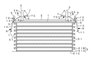
以下、本発明の実施の形態を図面に基づき詳述する。図において、51、51、・・・は合成樹脂製の育苗箱1(以下、箱51と称する。)を示し、該各箱51は上方が開放した横長四角形の箱本体51Aと、該箱本体51Aの上端外縁に枠状に形成したフランジ51Bと、箱本体51Aの底部外面に形成したリブ51Cとから形成してある。
1は前記箱51を運搬し、また積重するための運搬具を構成する金属製の枠体を示す。該枠体1は横長の前後枠材1A、1Bと、該前後枠材1A,1Bの両端に連結した左右一対の横枠材1C、1Cとから横長四角形に形成してあり、長手方向両端寄りに位置して前後枠材1A、1B間に左右一対の支持材1D、1Dが架設してある。
Hereinafter, embodiments of the present invention will be described in detail with reference to the drawings. In the figure, 51, 51, ... Indicates a
2は前記左右一対の支持材1D、1D間に横架した金属製の支持軸で、該支持軸2は枠体1の前後幅の略中間に位置させて配設してある。3、3は作業者の平均的肩幅に見合う間隔で支持軸2の両端側に、前後方向に回動可能に設けた左右一対の持ち手を示す。該各持ち手3は角型U字状に形成し、下端が支持軸2に嵌合する受け材3Aと、該受け材3Aの上端に架設した握り部3Bとから構成してあり、図6に示す矢視イ、ロ方向の前後方向に枠体1の前後枠材1A、1Bに当たるまで回動可能に設けてある。
4、4は枠体1の横枠材1C、1Cの各々に回動可能に嵌着した回動支持体を示す。5は該回動支持体4を構成し、横枠材1C、1Cに外嵌した可動筒で、該可動筒5の外面に接線方向に略四角形の基板6が略垂直の状態で固着してあり、基板6には上下に軸穴6A、6Bが夫々穿設してある。
7は該基板6の軸穴6Bに挿着した取付けねじ8により前後方向に回動可能に設けた可動操作体を示す。該可動操作体7は軸穴を有するボス7Aと、該ボス7Aから略Y字状に伸長して略中間の屈曲部7B1から平行に伸長し、該屈曲部7B1より先端側7B2を前記持ち手3の受け材3Aと握り部3Bの間に嵌入させた腕材7Bと、持ち手3より横方向内側に位置して該腕材7B、7Bの先端に架設した指掛け部7Cとから構成してある。
そして、可動操作体7は図3に示すように、回動支持体4を中心に矢示ハ、ニ方向の上下方向に昇降可能であり、かつ、取付けねじ8は支持軸2と同一軸線上に位置させてあるので、図6に示すように可動操作体7は持ち手3と一体に矢視イ、ロ方向の前後方向に回動可能になっている。
Then, as shown in FIG. 3, the
9、9は前記可動支持体4に連結し、枠体1の横幅方向両端に配設した左右一対の可動挟持体を示す。該各可動挟持体9は、逆U字状の支持材10と、該支持材10の下端に内向き水平方向に固着した帯板状の係合部11と、幅方向両端側が内向きに屈曲した平面視で略凵字状の板材からなり、支持材10に外側から当接して締着ねじ12で基板6に螺着する押え板13とから構成してある。
そして、箱51のフランジ51Bの裏に形成してある補強リブはメーカーによって長さが相違することから、係合部11にV字状の切込みを形成してある。
Since the length of the reinforcing rib formed on the back of the flange 51B of the
上述の構成からなる可動挟持体9は、締着ねじ12を緩めて係合部11の上下方向の高さ位置を調整し、締着ねじ12を締めることで、運搬する積重した箱51の段数に応じた位置に係合部11を設定することができる。
また、可動操作体7は可動挟持体9より重量を重くすることにより、使用待機時には可動挟持体9は図3に実線で示す外側方向に拡開した状態になるので、可動操作体7を引上げるだけで積重した箱51を速やかに挟持することができる。
In the
Further, since the
なお、箱51にはサイズの異なる種々のものがあるが、各種の箱51の高さ寸法は決まっているので、可動挟持体9の支持材10に目盛りを形成しておくことで、係合部11の位置設定を容易に、速やかに行うことができる。
また、可動挟持体9を構成する支持材10と係合部11はサイズの異なる複数種を用意しておくことで、多様な箱51に容易に対応することができる。
There are various types of
Further, by preparing a plurality of types of the
本実施の形態は上述の構成からなるもので、次にその作用について説明する。
先ず、運搬する最上段の箱51の上に枠体1を乗せ、左右の係合部11、11が積重する最下段の箱51のフランジ5Bに係止するように支持材10の上下方向の高さを設定し、押え板13で支持材10を基板6に挟んだ状態にして締付けねじ12で押え板13を締着して固定することにより、係合部11の高さ位置を決める。
そして、使用待機状態では可動挟持体9は図3に示す拡開した状態にあるから、枠体1を最上段の箱51に当てた状態にして可動操作体7を引上げると、可動挟持体9が矢示ホ方向に回動して係合部11が最下段の箱51のフランジ51Bに係合する。
The present embodiment has the above-mentioned configuration, and the operation thereof will be described next.
First, the
Since the
一方の持ち手3と可動操作体7を一体に持ち上げて可動挟持体9を積重した箱51に係合することで、他方の可動挟持体9も同様の操作で係合部11を最下段の箱51のフランジ51Bに容易に係合することができる。そして、可動挟持体9の係合部11には下向きに箱51の重量が掛っており、横方向に拡開することはないから、持ち手3を持った状態だけで箱51を持ち上げ、運搬することができる。
また、運搬後に箱51から運搬具を外す場合も、可動操作体7から指を離すだけで可動挟持体9が開き、係合部11が外方に回転してフランジ51Bから簡単に外すことができる。
By lifting one
Further, even when the carrier is removed from the
しかも、持ち手3と可動操作体7は前後方向に一体に回動可能であるから、作業者が腕を高く上げて積重する場合でも、図7に示すように手と腕を手前に引き寄せることで高い位置に持ち上げることができる。この際、腕と手首に掛る負担を小さくすることができるから手首を傷めることがない。
また、持ち手3と可動操作体7を手前に引き込めることで、上半身を前屈みにすることなく箱51を持ち上げることができるから、腰への負担も小さくできる。
Moreover, since the
Further, by retracting the
なお、持ち手3は高さ方向に長く、可動操作体7は腕材7Aを長く設定することにより、床面のような低い位置での移動や、水等の液体に浸す状態の時でも手を濡らすことなく作業ができる。
By setting the
1 枠体
2 支持軸
3 持ち手
3B 握り部
5 回動支持体
7 可動操作体
7B 腕材
7C 指掛け部
9 可動挟持体
10 支持材
11 係合部
1
Claims (6)
Priority Applications (1)
| Application Number | Priority Date | Filing Date | Title |
|---|---|---|---|
| JP2020113945A JP7387169B2 (en) | 2020-07-01 | 2020-07-01 | Stacking box carrier |
Applications Claiming Priority (1)
| Application Number | Priority Date | Filing Date | Title |
|---|---|---|---|
| JP2020113945A JP7387169B2 (en) | 2020-07-01 | 2020-07-01 | Stacking box carrier |
Publications (2)
| Publication Number | Publication Date |
|---|---|
| JP2022012249A true JP2022012249A (en) | 2022-01-17 |
| JP7387169B2 JP7387169B2 (en) | 2023-11-28 |
Family
ID=80148568
Family Applications (1)
| Application Number | Title | Priority Date | Filing Date |
|---|---|---|---|
| JP2020113945A Active JP7387169B2 (en) | 2020-07-01 | 2020-07-01 | Stacking box carrier |
Country Status (1)
| Country | Link |
|---|---|
| JP (1) | JP7387169B2 (en) |
Citations (6)
| Publication number | Priority date | Publication date | Assignee | Title |
|---|---|---|---|---|
| JP3062740U (en) * | 1999-04-05 | 1999-10-15 | 礼二郎 渡部 | Box transportation equipment |
| JP2000050737A (en) * | 1998-08-12 | 2000-02-22 | Yoshitoku Noki Kk | Holder for carrying seedling box |
| US20050005519A1 (en) * | 2003-07-10 | 2005-01-13 | Raker Timothy R. | Shipping cradle for trays of seedlings and the like |
| JP3157784U (en) * | 2009-11-19 | 2010-03-04 | 勝時 西森 | Pot transfer device |
| JP2016195696A (en) * | 2015-04-06 | 2016-11-24 | 株式会社プラナ | Cleaning mop |
| JP3215899U (en) * | 2018-02-09 | 2018-04-19 | 聡 黒壁 | Stacking box transporter |
-
2020
- 2020-07-01 JP JP2020113945A patent/JP7387169B2/en active Active
Patent Citations (6)
| Publication number | Priority date | Publication date | Assignee | Title |
|---|---|---|---|---|
| JP2000050737A (en) * | 1998-08-12 | 2000-02-22 | Yoshitoku Noki Kk | Holder for carrying seedling box |
| JP3062740U (en) * | 1999-04-05 | 1999-10-15 | 礼二郎 渡部 | Box transportation equipment |
| US20050005519A1 (en) * | 2003-07-10 | 2005-01-13 | Raker Timothy R. | Shipping cradle for trays of seedlings and the like |
| JP3157784U (en) * | 2009-11-19 | 2010-03-04 | 勝時 西森 | Pot transfer device |
| JP2016195696A (en) * | 2015-04-06 | 2016-11-24 | 株式会社プラナ | Cleaning mop |
| JP3215899U (en) * | 2018-02-09 | 2018-04-19 | 聡 黒壁 | Stacking box transporter |
Also Published As
| Publication number | Publication date |
|---|---|
| JP7387169B2 (en) | 2023-11-28 |
Similar Documents
| Publication | Publication Date | Title |
|---|---|---|
| US8226092B2 (en) | Equipment carrier | |
| CN215752437U (en) | Trolley assembly of workbench | |
| US20180290288A1 (en) | Portable workbench assembly | |
| CN103118578B (en) | Cleaner | |
| US5641170A (en) | Portable tool carrier and display box | |
| EP2837753B1 (en) | Panel Lifter | |
| CN112469619B (en) | Transport vehicle and transport device | |
| US11820411B2 (en) | Transport vehicle and transport device | |
| US6347907B1 (en) | Dolly and method of use | |
| JP7387169B2 (en) | Stacking box carrier | |
| US7784842B1 (en) | Hole digging device | |
| JP3215899U (en) | Stacking box transporter | |
| US2636626A (en) | Table moving dolly | |
| US979053A (en) | Hand-truck. | |
| JP3160619U (en) | Nursery box lifting tool | |
| JP2000050737A (en) | Holder for carrying seedling box | |
| CN214644164U (en) | A convenient edge cutting device for kraft paper | |
| CN211732712U (en) | Grabbing device and brick stacking equipment | |
| JP3260445B2 (en) | Holder for cargo handling of large plates such as glass plates | |
| US133299A (en) | Improvement in implements for picking up and carrying bricks | |
| CN205386799U (en) | Multi -functional buck of many mesas | |
| CN220162488U (en) | Foldable sucker lifting appliance | |
| CN218085546U (en) | A collapsible accurate carrier for transport of marble piece | |
| JP3117920U (en) | Trolley trolley on casters | |
| US6533246B1 (en) | Shoe clamp |
Legal Events
| Date | Code | Title | Description |
|---|---|---|---|
| A621 | Written request for application examination |
Free format text: JAPANESE INTERMEDIATE CODE: A621 Effective date: 20230306 |
|
| A977 | Report on retrieval |
Free format text: JAPANESE INTERMEDIATE CODE: A971007 Effective date: 20230927 |
|
| TRDD | Decision of grant or rejection written | ||
| A01 | Written decision to grant a patent or to grant a registration (utility model) |
Free format text: JAPANESE INTERMEDIATE CODE: A01 Effective date: 20231031 |
|
| A61 | First payment of annual fees (during grant procedure) |
Free format text: JAPANESE INTERMEDIATE CODE: A61 Effective date: 20231108 |
|
| R150 | Certificate of patent or registration of utility model |
Ref document number: 7387169 Country of ref document: JP Free format text: JAPANESE INTERMEDIATE CODE: R150 |