JP2022013017A - 緩衝器 - Google Patents
緩衝器 Download PDFInfo
- Publication number
- JP2022013017A JP2022013017A JP2020115279A JP2020115279A JP2022013017A JP 2022013017 A JP2022013017 A JP 2022013017A JP 2020115279 A JP2020115279 A JP 2020115279A JP 2020115279 A JP2020115279 A JP 2020115279A JP 2022013017 A JP2022013017 A JP 2022013017A
- Authority
- JP
- Japan
- Prior art keywords
- valve seat
- piston
- valve
- side chamber
- shock absorber
- Prior art date
- Legal status (The legal status is an assumption and is not a legal conclusion. Google has not performed a legal analysis and makes no representation as to the accuracy of the status listed.)
- Granted
Links
Images


Classifications
-
- F—MECHANICAL ENGINEERING; LIGHTING; HEATING; WEAPONS; BLASTING
- F16—ENGINEERING ELEMENTS AND UNITS; GENERAL MEASURES FOR PRODUCING AND MAINTAINING EFFECTIVE FUNCTIONING OF MACHINES OR INSTALLATIONS; THERMAL INSULATION IN GENERAL
- F16F—SPRINGS; SHOCK-ABSORBERS; MEANS FOR DAMPING VIBRATION
- F16F9/00—Springs, vibration-dampers, shock-absorbers, or similarly-constructed movement-dampers using a fluid or the equivalent as damping medium
- F16F9/10—Springs, vibration-dampers, shock-absorbers, or similarly-constructed movement-dampers using a fluid or the equivalent as damping medium using liquid only; using a fluid of which the nature is immaterial
- F16F9/14—Devices with one or more members, e.g. pistons, vanes, moving to and fro in chambers and using throttling effect
- F16F9/16—Devices with one or more members, e.g. pistons, vanes, moving to and fro in chambers and using throttling effect involving only straight-line movement of the effective parts
- F16F9/18—Devices with one or more members, e.g. pistons, vanes, moving to and fro in chambers and using throttling effect involving only straight-line movement of the effective parts with a closed cylinder and a piston separating two or more working spaces therein
- F16F9/185—Bitubular units
- F16F9/187—Bitubular units with uni-directional flow of damping fluid through the valves
-
- F—MECHANICAL ENGINEERING; LIGHTING; HEATING; WEAPONS; BLASTING
- F16—ENGINEERING ELEMENTS AND UNITS; GENERAL MEASURES FOR PRODUCING AND MAINTAINING EFFECTIVE FUNCTIONING OF MACHINES OR INSTALLATIONS; THERMAL INSULATION IN GENERAL
- F16F—SPRINGS; SHOCK-ABSORBERS; MEANS FOR DAMPING VIBRATION
- F16F9/00—Springs, vibration-dampers, shock-absorbers, or similarly-constructed movement-dampers using a fluid or the equivalent as damping medium
- F16F9/32—Details
- F16F9/3207—Constructional features
- F16F9/3214—Constructional features of pistons
-
- F—MECHANICAL ENGINEERING; LIGHTING; HEATING; WEAPONS; BLASTING
- F16—ENGINEERING ELEMENTS AND UNITS; GENERAL MEASURES FOR PRODUCING AND MAINTAINING EFFECTIVE FUNCTIONING OF MACHINES OR INSTALLATIONS; THERMAL INSULATION IN GENERAL
- F16F—SPRINGS; SHOCK-ABSORBERS; MEANS FOR DAMPING VIBRATION
- F16F9/00—Springs, vibration-dampers, shock-absorbers, or similarly-constructed movement-dampers using a fluid or the equivalent as damping medium
- F16F9/32—Details
- F16F9/34—Special valve constructions; Shape or construction of throttling passages
- F16F9/348—Throttling passages in the form of annular discs or other plate-like elements which may or may not have a spring action, operating in opposite directions or singly, e.g. annular discs positioned on top of the valve or piston body
Landscapes
- Engineering & Computer Science (AREA)
- General Engineering & Computer Science (AREA)
- Mechanical Engineering (AREA)
- Fluid-Damping Devices (AREA)
Abstract
Description
Claims (5)
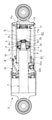
- シリンダと前記シリンダ内に軸方向へ移動自在に挿入されるロッドとを有する伸縮体と、
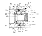
前記伸縮体内に2つの流体室を仕切るとともに前記流体室同士を連通する通路を有する隔壁部材と、
環状であって前記隔壁部材に軸方向に遠近可能であって前記通路を開閉するバルブとを備え、
前記隔壁部材は、前記バルブに臨む端部から前記軸方向に突出して前記バルブの内周面側が着座する環状の内周弁座と、前記バルブに臨む端部から前記軸方向へ突出し前記バルブの外周面側が着座する環状の外周弁座と、前記バルブに臨む端部から前記軸方向へ突出する中間弁座とを有し、
前記通路および前記中間弁座は、前記内周弁座と前記外周弁座との間に形成される
ことを特徴とする緩衝器。 - 前記中間弁座の突出高さは、前記内周弁座および前記外周弁座の突出高さと同じか或いは低い
ことを特徴とする請求項1に記載の緩衝器。 - 前記通路は、前記隔壁部材に同一円周上に複数設けられており、
前記中間弁座は、前記通路間に設けられる
ことを特徴とする請求項1または2に記載の緩衝器。 - 前記中間弁座は、前記隔壁部材の前記内周弁座と前記外周弁座との間に周方向に環状に形成されており、
前記通路は、前記内周弁座と前記中間弁座との間および前記中間弁座と前記外周弁座との間のそれぞれに複数設けられる
ことを特徴とする請求項1または2に記載の緩衝器。 - 前記隔壁部材は、前記シリンダ内に移動自在に挿入されるとともに前記シリンダ内を流体室である伸側室と圧側室とに区画するピストンであって、
前記通路は、前記伸側室と前記圧側室とを連通し、
流体を貯留するリザーバと、
前記伸側室と前記リザーバとを連通する排出通路と、
前記排出通路に設けられて前記伸側室から前記リザーバへ向かう前記流体の流れのみを許容するとともに前記流体の流れに抵抗を与える減衰バルブと、
前記リザーバと前記圧側室とを連通する吸込通路と、
前記吸込通路に設けられて前記リザーバから前記圧側室へ向かう前記流体の流れにのみを許容する吸込チェックバルブとを備え、
前記バルブは、前記通路を前記流体が前記圧側室から前記伸側室へ向かう方向へ流れのみを許容するチェックバルブである
ことを特徴とする請求項1から4のいずれか一項に記載の緩衝器。
Priority Applications (2)
| Application Number | Priority Date | Filing Date | Title |
|---|---|---|---|
| JP2020115279A JP7481929B2 (ja) | 2020-07-03 | 2020-07-03 | 緩衝器 |
| CN202110705517.0A CN113883207B (zh) | 2020-07-03 | 2021-06-24 | 缓冲器 |
Applications Claiming Priority (1)
| Application Number | Priority Date | Filing Date | Title |
|---|---|---|---|
| JP2020115279A JP7481929B2 (ja) | 2020-07-03 | 2020-07-03 | 緩衝器 |
Publications (2)
| Publication Number | Publication Date |
|---|---|
| JP2022013017A true JP2022013017A (ja) | 2022-01-18 |
| JP7481929B2 JP7481929B2 (ja) | 2024-05-13 |
Family
ID=79010515
Family Applications (1)
| Application Number | Title | Priority Date | Filing Date |
|---|---|---|---|
| JP2020115279A Active JP7481929B2 (ja) | 2020-07-03 | 2020-07-03 | 緩衝器 |
Country Status (2)
| Country | Link |
|---|---|
| JP (1) | JP7481929B2 (ja) |
| CN (1) | CN113883207B (ja) |
Citations (6)
| Publication number | Priority date | Publication date | Assignee | Title |
|---|---|---|---|---|
| JPS56122845U (ja) * | 1980-02-19 | 1981-09-18 | ||
| JPS6314038U (ja) * | 1986-07-14 | 1988-01-29 | ||
| JPH0266333A (ja) * | 1988-04-04 | 1990-03-06 | Atsugi Unisia Corp | 液圧緩衝器 |
| JP2005299791A (ja) * | 2004-04-12 | 2005-10-27 | Kayaba Ind Co Ltd | 緩衝器の減衰バルブ |
| JP2015224780A (ja) * | 2014-05-30 | 2015-12-14 | Kyb株式会社 | 緩衝器 |
| WO2020137207A1 (ja) * | 2018-12-25 | 2020-07-02 | 日立オートモティブシステムズ株式会社 | 緩衝器 |
Family Cites Families (3)
| Publication number | Priority date | Publication date | Assignee | Title |
|---|---|---|---|---|
| KR20040024705A (ko) * | 2002-09-16 | 2004-03-22 | 주식회사 만도 | 쇽 업소버의 바디밸브 |
| CN2859081Y (zh) * | 2005-12-31 | 2007-01-17 | 南阳金冠汽车减振器有限公司 | 液压减振器压缩阻尼阀 |
| CN210565969U (zh) * | 2019-08-14 | 2020-05-19 | 台州九桔科技股份有限公司 | 一种筒式减振器 |
-
2020
- 2020-07-03 JP JP2020115279A patent/JP7481929B2/ja active Active
-
2021
- 2021-06-24 CN CN202110705517.0A patent/CN113883207B/zh active Active
Patent Citations (6)
| Publication number | Priority date | Publication date | Assignee | Title |
|---|---|---|---|---|
| JPS56122845U (ja) * | 1980-02-19 | 1981-09-18 | ||
| JPS6314038U (ja) * | 1986-07-14 | 1988-01-29 | ||
| JPH0266333A (ja) * | 1988-04-04 | 1990-03-06 | Atsugi Unisia Corp | 液圧緩衝器 |
| JP2005299791A (ja) * | 2004-04-12 | 2005-10-27 | Kayaba Ind Co Ltd | 緩衝器の減衰バルブ |
| JP2015224780A (ja) * | 2014-05-30 | 2015-12-14 | Kyb株式会社 | 緩衝器 |
| WO2020137207A1 (ja) * | 2018-12-25 | 2020-07-02 | 日立オートモティブシステムズ株式会社 | 緩衝器 |
Also Published As
| Publication number | Publication date |
|---|---|
| JP7481929B2 (ja) | 2024-05-13 |
| CN113883207A (zh) | 2022-01-04 |
| CN113883207B (zh) | 2025-11-28 |
Similar Documents
| Publication | Publication Date | Title |
|---|---|---|
| US11536344B2 (en) | Valve and shock absorber | |
| KR20120093255A (ko) | 디지털 밸브를 이용한 댐퍼 | |
| US20200003272A1 (en) | Damper | |
| JP5827871B2 (ja) | 油圧緩衝器 | |
| JP2017003017A (ja) | 緩衝器 | |
| US4442926A (en) | Simplified hydraulic damper | |
| JP4453000B2 (ja) | 油圧緩衝器 | |
| JP2009243634A (ja) | 液圧緩衝器 | |
| JP6255249B2 (ja) | ショックアブソーバ | |
| JP2022013017A (ja) | 緩衝器 | |
| WO2021166214A1 (ja) | 圧力緩衝装置 | |
| JP6501887B2 (ja) | シリンダ装置 | |
| JPH01238727A (ja) | ショックアブソーバ | |
| CN113883208B (zh) | 缓冲器 | |
| JP4898607B2 (ja) | 空圧緩衝器のバルブ構造 | |
| JP2019178692A (ja) | バルブシート部材、バルブ、及び緩衝器 | |
| JPH0642114Y2 (ja) | ショックアブソーバのバルブ構造 | |
| JP7465163B2 (ja) | 緩衝器および緩衝器の組み立て方法 | |
| JP6496197B2 (ja) | 緩衝器 | |
| JP2006183775A (ja) | 油圧緩衝器 | |
| JPH11153172A (ja) | 油圧緩衝器用チェック弁 | |
| JPS63152740A (ja) | 油圧緩衝器 | |
| JP2022187255A (ja) | 緩衝器 | |
| JP2007271065A (ja) | 油圧緩衝器 | |
| JP2024008421A (ja) | 減衰バルブおよび緩衝器 |
Legal Events
| Date | Code | Title | Description |
|---|---|---|---|
| A621 | Written request for application examination |
Free format text: JAPANESE INTERMEDIATE CODE: A621 Effective date: 20230519 |
|
| A977 | Report on retrieval |
Free format text: JAPANESE INTERMEDIATE CODE: A971007 Effective date: 20231225 |
|
| A131 | Notification of reasons for refusal |
Free format text: JAPANESE INTERMEDIATE CODE: A131 Effective date: 20240109 |
|
| A521 | Request for written amendment filed |
Free format text: JAPANESE INTERMEDIATE CODE: A523 Effective date: 20240222 |
|
| TRDD | Decision of grant or rejection written | ||
| A01 | Written decision to grant a patent or to grant a registration (utility model) |
Free format text: JAPANESE INTERMEDIATE CODE: A01 Effective date: 20240402 |
|
| A61 | First payment of annual fees (during grant procedure) |
Free format text: JAPANESE INTERMEDIATE CODE: A61 Effective date: 20240426 |
|
| R150 | Certificate of patent or registration of utility model |
Ref document number: 7481929 Country of ref document: JP Free format text: JAPANESE INTERMEDIATE CODE: R150 |