JP2022057504A - Appearance inspection device - Google Patents

Appearance inspection device Download PDF

Info

Publication number
JP2022057504A
JP2022057504A JP2020165795A JP2020165795A JP2022057504A JP 2022057504 A JP2022057504 A JP 2022057504A JP 2020165795 A JP2020165795 A JP 2020165795A JP 2020165795 A JP2020165795 A JP 2020165795A JP 2022057504 A JP2022057504 A JP 2022057504A
Authority
JP
Japan
Prior art keywords
work
unit
light
image
inspection target
Prior art date
Legal status (The legal status is an assumption and is not a legal conclusion. Google has not performed a legal analysis and makes no representation as to the accuracy of the status listed.)
Granted
Application number
JP2020165795A
Other languages
Japanese (ja)
Other versions
JP7593034B2 (en
Inventor
賢也 坂東
Kenya Bando
昭 野村
Akira Nomura
Current Assignee (The listed assignees may be inaccurate. Google has not performed a legal analysis and makes no representation or warranty as to the accuracy of the list.)
Nidec Powertrain Systems Corp
Original Assignee
Nidec Tosok Corp
Priority date (The priority date is an assumption and is not a legal conclusion. Google has not performed a legal analysis and makes no representation as to the accuracy of the date listed.)
Filing date
Publication date
Application filed by Nidec Tosok Corp filed Critical Nidec Tosok Corp
Priority to JP2020165795A priority Critical patent/JP7593034B2/en
Publication of JP2022057504A publication Critical patent/JP2022057504A/en
Application granted granted Critical
Publication of JP7593034B2 publication Critical patent/JP7593034B2/en
Active legal-status Critical Current
Anticipated expiration legal-status Critical

Links

Images

Landscapes

  • Investigating Materials By The Use Of Optical Means Adapted For Particular Applications (AREA)

Abstract

To provide an appearance inspection device that can reduce the length of time for an inspection.SOLUTION: The appearance inspection device inspects a workpiece for the appearance. The appearance inspection device includes: a light application unit for applying light to a workpiece; a light receiving unit for receiving light applied from the light application unit and reflected by the workpiece; an imaging processing unit for generating an image of the whole workpiece on the basis of the result of light reception by the light receiving unit; and a determination unit for extracting an inspection target image of an inspection target region to inspect of the whole workpiece, taking in the inspection target image, comparing a reference image as a basis of determination as to whether the inspection target region has an excellent appearance and the inspection target image, and determining whether the inspection target region has an excellent appearance.SELECTED DRAWING: Figure 16

Description

本発明は、外観検査装置に関する。 The present invention relates to a visual inspection apparatus.

部品を検査する検査装置が知られている(例えば、特許文献1参照)。特許文献1に記載の検査装置は、部品を撮像する撮像部と、前記撮像部からの画像データ(撮像信号)を処理する信号処理部とを備える。 Inspection devices for inspecting parts are known (see, for example, Patent Document 1). The inspection device described in Patent Document 1 includes an imaging unit that captures an image of a component and a signal processing unit that processes image data (imaging signal) from the imaging unit.

特開2004-023256号公報Japanese Unexamined Patent Publication No. 2004-023256

特許文献1に記載の検査装置では、部品の一部分に対する部分検査を行う際には、まず、部品全体の画像データを信号処理部に取り込む。次いで、部品全体の画像データから、検査対象となる前記一部分の画像データをさらに取り込んで、当該画像データに基づいて部分検査が行われる。このように、部分検査では、部品全体の画像データを取り込んでいるため、検査対象以外の画像データ、すなわち、部分検査に必要がない(用いられない)画像データも取り込むことととなり、その分、検査時間が長くなるという問題が生じる。
本発明の目的は、検査時間の短縮が可能な外観検査装置を提供することにある。
In the inspection device described in Patent Document 1, when performing a partial inspection on a part of a part, first, the image data of the entire part is taken into the signal processing unit. Next, the image data of the part to be inspected is further taken in from the image data of the entire component, and the partial inspection is performed based on the image data. In this way, since the partial inspection captures the image data of the entire part, the image data other than the inspection target, that is, the image data that is not necessary (not used) for the partial inspection is also captured. There is a problem that the inspection time becomes long.
An object of the present invention is to provide a visual inspection apparatus capable of shortening an inspection time.

本発明の外観検査装置の一つの態様は、ワークの外観を検査する外観検査装置であって、
ワークに向けて光を照射する光照射ユニットと、
光照射ユニットからの光がワークで反射した反射光を受光する受光ユニットと、
受光ユニットでの受光結果に基づいてワーク全体の画像を生成する画像処理部と、
ワーク全体のうちの検査対象となる検査対象領域の検査対象画像を抽出し、検査対象画像を取り込んで、検査対象領域の外観の良否判断の基準となる基準画像と、検査対象画像とを比較して、良否判断を行う判断部とを備えることを特徴とする。
One aspect of the visual inspection device of the present invention is a visual inspection device for inspecting the appearance of a work.
A light irradiation unit that irradiates light toward the work,
A light receiving unit that receives the reflected light reflected by the work from the light from the light irradiation unit,
An image processing unit that generates an image of the entire work based on the light receiving result of the light receiving unit,
The inspection target image of the inspection target area of the entire work is extracted, the inspection target image is taken in, and the reference image that is the standard for judging the quality of the appearance of the inspection target area is compared with the inspection target image. It is characterized by having a judgment unit for making a pass / fail judgment.

本発明の外観検査装置の一つの態様によれば、検査時間の短縮が可能となる。 According to one aspect of the visual inspection apparatus of the present invention, the inspection time can be shortened.

図1は、本発明の外観検査装置の実施形態を示す平面図である。FIG. 1 is a plan view showing an embodiment of the visual inspection apparatus of the present invention. 図2は、図1中の矢印A方向から見た図である。FIG. 2 is a view seen from the direction of arrow A in FIG. 図3は、図1に示す外観検査装置の主要部のブロック図である。FIG. 3 is a block diagram of a main part of the visual inspection apparatus shown in FIG. 図4は、レーザ光の発光、受光状態を示す平面図である。FIG. 4 is a plan view showing a state of light emission and light reception of laser light. 図5は、良品となるコネクティングロッドへのレーザ光の照射状態を示す平面図である。FIG. 5 is a plan view showing a state in which a connecting rod, which is a non-defective product, is irradiated with a laser beam. 図6は、図5中のB-B線断面図である。FIG. 6 is a cross-sectional view taken along the line BB in FIG. 図7は、不良品となるコネクティングロッドへのレーザ光の照射状態を示す平面図である。FIG. 7 is a plan view showing a state in which a connecting rod, which is a defective product, is irradiated with a laser beam. 図8は、図5に示すコネクティングロッドの全体画像および検査対象画像である。FIG. 8 is an overall image of the connecting rod shown in FIG. 5 and an image to be inspected. 図9は、図7に示すコネクティングロッドの全体画像および検査対象画像である。FIG. 9 is an overall image of the connecting rod shown in FIG. 7 and an image to be inspected. 図10は、第1基準画像である。FIG. 10 is a first reference image. 図11は、第2基準画像である。FIG. 11 is a second reference image. 図12は、第3基準画像である。FIG. 12 is a third reference image. 図13は、コネクティングロッドの検査対象領域を示す平面図である。FIG. 13 is a plan view showing an inspection target area of the connecting rod. 図14は、コネクティングロッドの検査対象領域を示す平面図である。FIG. 14 is a plan view showing an inspection target area of the connecting rod. 図15は、図1に示す外観検査装置で実行される制御プログラムのフローチャートである。FIG. 15 is a flowchart of a control program executed by the visual inspection apparatus shown in FIG. 図16は、図15に示すフローチャート中のサブルーチンである。FIG. 16 is a subroutine in the flowchart shown in FIG.

図1~図16を参照して、本発明の外観検査装置の実施形態について説明する。なお、以下では、説明の便宜上、互いに直交する3軸をX軸、Y軸およびZ軸を設定する。一例として、X軸とY軸を含むXY平面が水平となっており、Z軸が鉛直となっている。本明細書中において、上下方向、水平方向、上側および下側とは、単に各部の相対位置関係を説明するための名称であり、実際の配置関係等は、これらの名称で示される配置関係等以外の配置関係等であってもよい。また、以下では、説明の都合上、図2および図6中の上側を「上(または上方)」、下側を「下(または下方)」と言うことがある。 An embodiment of the visual inspection apparatus of the present invention will be described with reference to FIGS. 1 to 16. In the following, for convenience of explanation, the X-axis, the Y-axis, and the Z-axis are set as the three axes orthogonal to each other. As an example, the XY plane including the X-axis and the Y-axis is horizontal, and the Z-axis is vertical. In the present specification, the vertical direction, the horizontal direction, the upper side and the lower side are merely names for explaining the relative positional relationship of each part, and the actual arrangement relationship and the like are the arrangement relationship and the like indicated by these names. It may be an arrangement relation other than the above. Further, in the following, for convenience of explanation, the upper side in FIGS. 2 and 6 may be referred to as “upper (or upper)” and the lower side may be referred to as “lower (or lower)”.

図1~図3に示す外観検査装置1は、ワーク9の外観を検査する装置である。外観検査装置1は、光学ユニット2と、搬送部4と、反転機構5と、報知部6と、制御部3とを備える。以下、各部の構成について説明する。
なお、ワーク9としては、特に限定されず、例えば、コネクティングロッド(略称:コンロッド)等の自動車部品等が挙げられる。本実施形態では、ワーク9がコネクティングロッドの場合を一例にして説明する。
The visual inspection device 1 shown in FIGS. 1 to 3 is a device for inspecting the appearance of the work 9. The visual inspection device 1 includes an optical unit 2, a transport unit 4, an inversion mechanism 5, a notification unit 6, and a control unit 3. Hereinafter, the configuration of each part will be described.
The work 9 is not particularly limited, and examples thereof include automobile parts such as a connecting rod (abbreviation: connecting rod). In this embodiment, the case where the work 9 is a connecting rod will be described as an example.

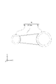
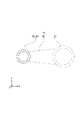
図4に示すように、ワーク9としてのコネクティングロッドは、リング状の大端部91と、リング状の小端部92と、大端部91と小端部92とを連結する連結部93とを有する。大端部91は、クランクシャフトと連結される部分である。小端部92は、ピストンと連結される部分である。また、ワーク9は、鍛造品である。 As shown in FIG. 4, the connecting rod as the work 9 includes a ring-shaped large end portion 91, a ring-shaped small end portion 92, and a connecting portion 93 connecting the large end portion 91 and the small end portion 92. Has. The large end portion 91 is a portion connected to the crankshaft. The small end portion 92 is a portion connected to the piston. The work 9 is a forged product.

搬送部4は、ワーク9を搬送する装置である。搬送部4の構成は、特に限定されないが、本実施形態では、ベルトコンベアである。そして、搬送部4がベルトコンベアで構成された場合、ワーク9は、ベルト41上に載置された状態で、X軸方向に沿って搬送される。ここで、「所定方向(例えばX軸方向)に沿う」とは、所定方向(例えばX軸方向)と並行な状態を言う。また、本実施形態での搬送方向は、X軸方向負側から正側に向かう方向となり、X軸方向負側が「搬送方向上流側」、X軸方向正側が「搬送方向下流側」となる。
また、ベルト41上でのワーク9は、搬送方向上流側に小端部92が位置し、搬送方向下流側に大端部91が位置した状態で載置され、その向き(姿勢)のまま搬送される。
The transport unit 4 is a device for transporting the work 9. The configuration of the transport unit 4 is not particularly limited, but in the present embodiment, it is a belt conveyor. When the transport unit 4 is composed of a belt conveyor, the work 9 is transported along the X-axis direction while being placed on the belt 41. Here, "along the predetermined direction (for example, the X-axis direction)" means a state parallel to the predetermined direction (for example, the X-axis direction). Further, the transport direction in the present embodiment is a direction from the negative side in the X-axis direction to the positive side, the negative side in the X-axis direction is the "upstream side in the transport direction", and the positive side in the X-axis direction is the "downstream side in the transport direction".
Further, the work 9 on the belt 41 is placed in a state where the small end portion 92 is located on the upstream side in the transport direction and the large end portion 91 is located on the downstream side in the transport direction, and the work 9 is transported in that direction (posture). Will be done.

図1に示すように、反転機構5は、ワーク9の搬送途中で、当該ワーク9を表裏反転させる装置である。反転機構5は、ワーク9を搬送方向上流側と下流側とから挟んで保持する保持部51と、保持部51をX軸方向と平行な軸O52回りに回転可能に支持する回転支持部52とを有する。そして、反転機構5は、保持部51でワーク9を保持した状態で、保持部51をワーク9ごと軸O52回りに180度回転させることができる。これにより、ワーク9の表裏を反転させることができる。 As shown in FIG. 1, the reversing mechanism 5 is a device that reverses the work 9 in the middle of transporting the work 9. The reversing mechanism 5 includes a holding portion 51 that sandwiches and holds the work 9 from the upstream side and the downstream side in the transport direction, and a rotary support portion 52 that rotatably supports the holding portion 51 around an axis O52 parallel to the X-axis direction. Has. Then, the reversing mechanism 5 can rotate the holding portion 51 together with the work 9 by 180 degrees around the axis O52 while the work 9 is held by the holding portion 51. As a result, the front and back of the work 9 can be reversed.

ワーク9を反転させる前は、当該ワーク9の表側に対する外観検査(以下、「第1検査(第1外観検査)」と言う。)を行うことができる。また、ワーク9を反転させた後は、当該ワーク9の裏側に対する外観検査(以下、「第2検査(第1外観検査)」と言う。)と行うことができる。そして、第1検査および第2検査の双方により、ワーク9の外観検査を過不足なく行うことができ、よって、ワーク9が良品かまたは不良品かを正確に判断することができる。なお、第1検査および第2検査には、ワーク9の全体の画像(全体画像)7が用いられる。また、以降では、良品のワーク9を「ワーク9A」と言い、不良品のワーク9を「ワーク9B」と言うことがある。 Before the work 9 is inverted, a visual inspection (hereinafter referred to as "first inspection (first visual inspection)") can be performed on the front side of the work 9. Further, after the work 9 is inverted, an appearance inspection on the back side of the work 9 (hereinafter referred to as "second inspection (first appearance inspection)") can be performed. Then, by both the first inspection and the second inspection, the appearance inspection of the work 9 can be performed without excess or deficiency, and therefore it is possible to accurately determine whether the work 9 is a good product or a defective product. The entire image (overall image) 7 of the work 9 is used for the first inspection and the second inspection. Further, hereinafter, the non-defective work 9 may be referred to as “work 9A”, and the defective work 9 may be referred to as “work 9B”.

図1に示すように、本実施形態では、光学ユニット2は、ベルト41に対し、Z軸方向正側(ベルト41の上側)に12個配置される。各光学ユニット2は、ワーク9を撮像するユニットである。
また、これら12個の光学ユニット2のうち、6個の光学ユニット2は、搬送方向上流側で第1検査に用いられる。また、残りの6個の光学ユニット2は、搬送方向下流側で第2検査に用いられる。上流側の6個の光学ユニット2と、下流側の6個の光学ユニット2とは、配置箇所が異なること以外は、同じ構成であるため、上流側の6個の光学ユニット2について、代表的に説明する。
As shown in FIG. 1, in the present embodiment, twelve optical units 2 are arranged on the positive side in the Z-axis direction (upper side of the belt 41) with respect to the belt 41. Each optical unit 2 is a unit that captures an image of the work 9.
Further, of these 12 optical units 2, 6 optical units 2 are used for the first inspection on the upstream side in the transport direction. Further, the remaining 6 optical units 2 are used for the second inspection on the downstream side in the transport direction. Since the six optical units 2 on the upstream side and the six optical units 2 on the downstream side have the same configuration except that the arrangement locations are different, the six optical units 2 on the upstream side are representative. Explain to.

6個の光学ユニット2は、それぞれ、光照射部23と、受光部24とを有する。そして、光学ユニット2、1つ当たり、隣り合って配置された光照射部23と受光部24とが組(対)となる。また、各光学ユニット2では、光照射部23と受光部24とが、ワーク9との距離を測定するレーザ測長器を構成する。これにより、距離の大小に応じてワーク9の凹凸等の外形形状(3次元形状)を検出することができる。そして、レーザ測長器での検出結果に基づいて、ワーク9の全体の画像7を正確に得ることができる。 Each of the six optical units 2 has a light irradiation unit 23 and a light receiving unit 24. Then, for each of the optical units 2, the light irradiation unit 23 and the light receiving unit 24 arranged adjacent to each other form a pair. Further, in each optical unit 2, the light irradiation unit 23 and the light receiving unit 24 form a laser length measuring device for measuring the distance to the work 9. Thereby, the outer shape (three-dimensional shape) such as the unevenness of the work 9 can be detected according to the size of the distance. Then, based on the detection result of the laser length measuring instrument, the entire image 7 of the work 9 can be accurately obtained.

なお、光照射部23と受光部24とは、互いに軸線同士が所定の角度(仰角)θをもって配置されている。角度θは、特に限定されないが、例えば、20°~30°が好ましい。
また、外観検査装置1では、光照射部23と受光部24とが光学ユニット2を構成すると言うこととは別に、6個の光照射部23が光照射ユニット21を構成し、6個の受光部24が受光ユニット22を構成すると言うこともできる。
The light irradiation unit 23 and the light receiving unit 24 are arranged so that their axes are aligned with each other at a predetermined angle (elevation angle) θ. The angle θ is not particularly limited, but is preferably 20 ° to 30 °, for example.
Further, in the visual inspection device 1, apart from the fact that the light irradiation unit 23 and the light receiving unit 24 form the optical unit 2, the six light irradiation units 23 form the light irradiation unit 21 and the six light receiving units are received. It can also be said that the unit 24 constitutes the light receiving unit 22.

図1、図2に示すように、各光照射部23(光照射ユニット21)は、ワーク9に向けて光LBを照射することができる。光LBとしては、特に、レーザ光が好ましい。レーザ光は、指向性に優れている。これにより、光LBをワーク9に容易かつ正確に照射することができる。
また、各光照射部23は、レーザ光(光LB)をワーク9の搬送方向と交差する方向、すなわち、Y軸方向に沿ったライン状に照射することができる。これにより、図5、図7に示すように、ワーク9に対して、Y軸方向に沿ったライン状のレーザ光が当たる。そして、ワーク9の平面視での形状に応じて、すなわち、ワーク9が良品なのか不良品なのかに応じて、ワーク9上でレーザ光が当たる位置(状態)が変わる(図5~図7参照)。従って、外観検査装置1は、「光切断法」によりワーク9の平面視での形状を検出する装置であると言うことができる。また、ワーク9に対しては、レーザ光がライン状に当たるため、例えばレーザ光がスポット状(点状)に当たる場合に比べて、スムースな画像7を取得することができる。
As shown in FIGS. 1 and 2, each light irradiation unit 23 (light irradiation unit 21) can irradiate the work 9 with light LB. As the optical LB, laser light is particularly preferable. Laser light has excellent directivity. This makes it possible to easily and accurately irradiate the work 9 with the light LB.
Further, each light irradiation unit 23 can irradiate the laser beam (light LB) in a direction intersecting the transport direction of the work 9, that is, in a line shape along the Y-axis direction. As a result, as shown in FIGS. 5 and 7, a line-shaped laser beam along the Y-axis direction hits the work 9. Then, the position (state) where the laser beam hits on the work 9 changes according to the shape of the work 9 in a plan view, that is, whether the work 9 is a good product or a defective product (FIGS. 5 to 7). reference). Therefore, it can be said that the visual inspection device 1 is a device that detects the shape of the work 9 in a plan view by the "light cutting method". Further, since the laser beam hits the work 9 in a line shape, a smooth image 7 can be obtained as compared with the case where the laser beam hits a spot shape (point shape), for example.

図4に示すように、各受光部24(受光ユニット22)は、当該受光部24と対をなす光照射部23からの光LBが、ワーク9で反射した反射光LB’を受光することができる。受光部24としては、特に限定されず、例えば、CCDカメラ等を用いることができる。 As shown in FIG. 4, in each light receiving unit 24 (light receiving unit 22), the light LB from the light irradiation unit 23 paired with the light receiving unit 24 may receive the reflected light LB'reflected by the work 9. can. The light receiving unit 24 is not particularly limited, and for example, a CCD camera or the like can be used.

図1に示すように、外観検査装置1では、ワーク9の搬送方向(X軸方向)に沿って光学ユニット2が2つずつ設けられ、ワーク9の搬送方向と交差する方向(Y軸方向)に沿って光学ユニット2が3つずつ設けられる。すなわち、光学ユニット2は、2行3列に配置される。
そして、Y軸方向に沿って並ぶ3つの光学ユニット2のうち、中央に位置する光学ユニット2は、平面視でベルト41の中心線O41上に配置され、残りの2つの光学ユニット2は、中央の光学ユニット2から等距離に配置される。
As shown in FIG. 1, in the visual inspection apparatus 1, two optical units 2 are provided along the transport direction (X-axis direction) of the work 9, and the direction intersects the transport direction of the work 9 (Y-axis direction). Three optical units 2 are provided along the line. That is, the optical units 2 are arranged in 2 rows and 3 columns.
Of the three optical units 2 arranged along the Y-axis direction, the optical unit 2 located at the center is arranged on the center line O41 of the belt 41 in a plan view, and the remaining two optical units 2 are at the center. It is arranged equidistant from the optical unit 2 of the above.

また、Y軸方向に沿って並ぶ3つの光学ユニット2は光照射部23から互いに波長が異なる光LBを照射することができる。以下では、赤色の光LBを照射する光学ユニット2を「光学ユニット2R」と言い、緑色の光LBを照射する光学ユニット2を「光学ユニット2G」と言い、青色の光LBを照射する光学ユニット2を「光学ユニット2B」と言う。 Further, the three optical units 2 arranged along the Y-axis direction can irradiate light LBs having different wavelengths from the light irradiation unit 23. In the following, the optical unit 2 that irradiates the red light LB is referred to as "optical unit 2R", the optical unit 2 that irradiates the green light LB is referred to as "optical unit 2G", and the optical unit that irradiates the blue light LB is referred to. 2 is referred to as "optical unit 2B".

搬送方向上流側では、3つの光学ユニット2は、Y軸方向負側から光学ユニット2B、光学ユニット2G、光学ユニット2Rの順に配置される。また、光学ユニット2B、光学ユニット2G、光学ユニット2Rの各光照射部23は、それぞれ、搬送方向上流側から下流側に向かって光LBを照射する。なお、各色の光LBは、ワーク9に対してほぼ同じ位置に照射される。 On the upstream side in the transport direction, the three optical units 2 are arranged in the order of the optical unit 2B, the optical unit 2G, and the optical unit 2R from the negative side in the Y-axis direction. Further, each of the light irradiation units 23 of the optical unit 2B, the optical unit 2G, and the optical unit 2R irradiates the light LB from the upstream side to the downstream side in the transport direction. The light LB of each color is applied to the work 9 at substantially the same position.

一方、搬送方向下流側では、3つの光学ユニット2は、Y軸方向負側から光学ユニット2R、光学ユニット2G、光学ユニット2Bの順に配置される。また、光学ユニット2B、光学ユニット2G、光学ユニット2Rの各光照射部23は、それぞれ、搬送方向下流側から上流側に向かって光LBを照射する。搬送方向下流側でも同様に、各色の光LBは、ワーク9に対してほぼ同じ位置に照射される。
また、搬送方向上流側と下流側とでは、光学ユニット2R同士が対向し、光学ユニット2B同士が対向し、光学ユニット2G同士が対向して配置される。
On the other hand, on the downstream side in the transport direction, the three optical units 2 are arranged in the order of the optical unit 2R, the optical unit 2G, and the optical unit 2B from the negative side in the Y-axis direction. Further, each of the light irradiation units 23 of the optical unit 2B, the optical unit 2G, and the optical unit 2R irradiates the light LB from the downstream side to the upstream side in the transport direction. Similarly, on the downstream side in the transport direction, the light LBs of each color are irradiated to substantially the same position with respect to the work 9.
Further, on the upstream side and the downstream side in the transport direction, the optical units 2R face each other, the optical units 2B face each other, and the optical units 2G face each other.

各受光部24は、波長が異なる光LB(反射光LB’)を個別に受光することができる。
例えば、光学ユニット2Rに着目すると、当該光学ユニット2Rを構成する光照射部23からは、赤色の光LBが照射される。光照射部23とともに光学ユニット2Rを構成する受光部24は、赤色の光LBが透過し、それ以外の波長の光LBの透過を遮断する特定波長透過フィルタが内蔵されている。これにより、受光部24は、赤色の光LBを安定して受光することができる。
Each light receiving unit 24 can individually receive light LB (reflected light LB') having a different wavelength.
For example, focusing on the optical unit 2R, red light LB is emitted from the light irradiation unit 23 constituting the optical unit 2R. The light receiving unit 24, which constitutes the optical unit 2R together with the light irradiation unit 23, has a built-in specific wavelength transmission filter that transmits red light LB and blocks the transmission of light LB of other wavelengths. As a result, the light receiving unit 24 can stably receive the red light LB.

同様に、光学ユニット2Gに着目すると、当該光学ユニット2Gを構成する光照射部23からは、緑色の光LBが照射される。光照射部23とともに光学ユニット2Gを構成する受光部24は、赤色の光LBが透過し、それ以外の波長の光LBの透過を遮断する特定波長透過フィルタが内蔵されている。これにより、緑色の光LBを安定して受光することができる。 Similarly, focusing on the optical unit 2G, green light LB is irradiated from the light irradiation unit 23 constituting the optical unit 2G. The light receiving unit 24, which constitutes the optical unit 2G together with the light irradiation unit 23, has a built-in specific wavelength transmission filter that transmits red light LB and blocks the transmission of light LB of other wavelengths. As a result, the green light LB can be stably received.

また、光学ユニット2Bに着目すると、当該光学ユニット2Bを構成する光照射部23からは、青色の光LBが照射される。光照射部23とともに光学ユニット2Bを構成する受光部24は、赤色の光LBが透過し、それ以外の波長の光LBの透過を遮断する特定波長透過フィルタが内蔵されている。これにより、青色の光LBを安定して受光することができる。 Focusing on the optical unit 2B, blue light LB is emitted from the light irradiation unit 23 constituting the optical unit 2B. The light receiving unit 24, which constitutes the optical unit 2B together with the light irradiation unit 23, has a built-in specific wavelength transmission filter that transmits red light LB and blocks the transmission of light LB of other wavelengths. As a result, the blue light LB can be stably received.

以上のような構成の光学ユニット2により、搬送方向上流側では、ワーク9を撮像する際、平面視でワーク9を中心に囲んで、死角の発生を防止することができる。これにより、第1検査を正確に行うのに十分な程度の撮像を行うことができる。
また、前述したように、Y軸方向に沿って並ぶ3つの光学ユニット2は、互いに波長が異なる光LBの発光と受光とがなされる。これにより、例えば光学ユニット2Rの光LBが光学ユニット2Gで受光されるのを防止する、すなわち、誤受光を防止することができ、よって、ワーク9を正確に撮像することができる。
With the optical unit 2 having the above configuration, on the upstream side in the transport direction, when the work 9 is imaged, the work 9 can be surrounded by the center in a plan view to prevent the occurrence of a blind spot. As a result, it is possible to perform imaging to a sufficient extent to accurately perform the first inspection.
Further, as described above, the three optical units 2 arranged along the Y-axis direction emit and receive light LB having different wavelengths from each other. Thereby, for example, it is possible to prevent the optical LB of the optical unit 2R from being received by the optical unit 2G, that is, to prevent erroneous light reception, so that the work 9 can be accurately imaged.

また、前述したように、光学ユニット2B、光学ユニット2G、光学ユニット2RがY軸方向に沿って配置される。このような配置は、例えば、光学ユニット2B、光学ユニット2G、光学ユニット2RをX軸方向に沿って配置した場合に比べて、外観検査装置1の全長を短くすることができる。これにより、ワーク9、1つ当たりの検査に要する撮像時間や搬送時間を短縮することができる。 Further, as described above, the optical unit 2B, the optical unit 2G, and the optical unit 2R are arranged along the Y-axis direction. In such an arrangement, the total length of the visual inspection device 1 can be shortened as compared with the case where the optical unit 2B, the optical unit 2G, and the optical unit 2R are arranged along the X-axis direction, for example. As a result, it is possible to shorten the imaging time and the transport time required for the inspection of each work 9.

また、図1に示すように、外観検査装置1は、第1カバー10Aと、第2カバー10Bとを備える。第1カバー10Aは、搬送方向上流側で第1検査に用いられる各光学ユニット2をワーク9ごと一括して外側から覆う。第2カバー10Bは、搬送方向上流側で第2検査に用いられる各光学ユニット2をワーク9ごと一括して外側から覆う。 Further, as shown in FIG. 1, the visual inspection apparatus 1 includes a first cover 10A and a second cover 10B. The first cover 10A collectively covers each optical unit 2 used for the first inspection on the upstream side in the transport direction together with the work 9 from the outside. The second cover 10B collectively covers each optical unit 2 used for the second inspection on the upstream side in the transport direction together with the work 9 from the outside.

第1カバー10Aおよび第2カバー10Bは、それぞれ、自然光等の外部(外側)からの光を遮断する光不透過性を有する。外部からの光は、撮像時のノイズとなるおそれがあるが、第1カバー10Aおよび第2カバー10Bにより、外部からの光を遮断して、ノイズを防止することができる。 The first cover 10A and the second cover 10B each have a light impermeable property of blocking light from the outside (outside) such as natural light. The light from the outside may cause noise at the time of imaging, but the first cover 10A and the second cover 10B can block the light from the outside and prevent the noise.

報知部6は、各種の情報を報知することができる。なお、各種の情報としては、例えば、後述する「良否判断において否と判断された検査対象領域94」や、その他、各光学ユニット2、搬送部4および反転機構5の各部の作動エラー等が挙げられる。また、報知部6での報知方法としては、例えば、音声による報知方法、発光による報知方法等が挙げられ、これらを単独または組み合わせて用いることができる。 The notification unit 6 can notify various information. In addition, as various information, for example, "inspection target area 94 which was judged as rejected in the quality judgment" which will be described later, and the operation error of each part of each optical unit 2, the transport part 4 and the reversing mechanism 5 and the like. Be done. Further, as the notification method in the notification unit 6, for example, a notification method by voice, a notification method by light emission, and the like can be mentioned, and these can be used alone or in combination.

図3に示すように、制御部3は、各光学ユニット2、搬送部4、反転機構5、報知部6に電気的に接続され、各部の作動をそれぞれ制御する。制御部3は、CPU31と、記憶部32とを有する。記憶部32には、例えば、外観検査を行うためのプログラムが予め記憶される。CPU31は、記憶部32に記憶されたプログラムを実行することができる。これにより、各光学ユニット2等が作動して、外観検査が行われる。
なお、本実施形態では、制御部3は、第1検査で用いられる光学ユニット2と、第2検査で用いられる光学ユニット2とを制御しているが、これに限定されない。例えば、第1検査で用いられる光学ユニット2を制御する制御部3と、第2検査で用いられる光学ユニット2を制御する制御部3とがそれぞれ設けられていてもよい。
また、搬送部4は、PLC(Programmable Logic Controller)にて制御されていてもよい。
As shown in FIG. 3, the control unit 3 is electrically connected to each optical unit 2, a transport unit 4, a reversing mechanism 5, and a notification unit 6 to control the operation of each unit. The control unit 3 has a CPU 31 and a storage unit 32. In the storage unit 32, for example, a program for performing a visual inspection is stored in advance. The CPU 31 can execute the program stored in the storage unit 32. As a result, each optical unit 2 and the like are operated to perform a visual inspection.
In the present embodiment, the control unit 3 controls the optical unit 2 used in the first inspection and the optical unit 2 used in the second inspection, but the present invention is not limited thereto. For example, a control unit 3 for controlling the optical unit 2 used in the first inspection and a control unit 3 for controlling the optical unit 2 used in the second inspection may be provided respectively.
Further, the transport unit 4 may be controlled by a PLC (Programmable Logic Controller).

ワーク9は、製造過程で、例えば、欠損、傷、打痕等の損傷が生じる場合がある。損傷が生じたワーク9は、不良品として扱われる。
外観検査装置1は、第1検査および第2検査の2つの検査結果に基づいて、ワーク9が良品であるか、または、不良品であるかを判断することができる。以下、ワーク9に対する良不良を判断する構成について説明する。
In the manufacturing process of the work 9, for example, damage such as defects, scratches, and dents may occur. The damaged work 9 is treated as a defective product.
The visual inspection device 1 can determine whether the work 9 is a non-defective product or a defective product based on the two inspection results of the first inspection and the second inspection. Hereinafter, a configuration for determining the quality of the work 9 will be described.

外観検査装置1では、ワーク9を複数の部位に分けて、各部位を検査対象領域94に設定する。これにより、ワーク9は、検査が行われるのに際し、互いに位置が異なる複数の検査対象領域94を有することとなる。本実施形態では、大端部91を検査対象領域94に設定する場合と、小端部92を検査対象領域94に設定する場合と、連結部93を検査対象領域94に設定する場合とがあり、代表的に大端部91を検査対象領域94に設定する場合について説明する。なお、図7に示すように、不良品であるワーク9Bは、大端部91の周方向の一部が欠損した欠損部95を有する。
また、外観検査装置1では、検査対象領域94が予め特定されており、光LBが照射される照射領域には、検査対象領域94が含まれる。
In the visual inspection apparatus 1, the work 9 is divided into a plurality of parts, and each part is set in the inspection target area 94. As a result, the work 9 has a plurality of inspection target areas 94 having different positions from each other when the inspection is performed. In the present embodiment, the large end portion 91 may be set in the inspection target area 94, the small end portion 92 may be set in the inspection target area 94, or the connecting portion 93 may be set in the inspection target area 94. , The case where the large end portion 91 is typically set in the inspection target area 94 will be described. As shown in FIG. 7, the defective work 9B has a defective portion 95 in which a part of the large end portion 91 in the circumferential direction is missing.
Further, in the visual inspection apparatus 1, the inspection target area 94 is specified in advance, and the irradiation target area 94 to which the light LB is irradiated includes the inspection target area 94.

図3に示すように、制御部3のCPU31は、画像処理部33としての機能を発揮する部分と、判断部34としての機能を発揮する部分とを有する。なお、本実施形態では、画像処理部33と、判断部34とは、1つのCPU31で機能が発揮されるが、これに限定されない。例えば、画像処理部33の機能を発揮するCPU31と、判断部34の機能を発揮するCPU31とがそれぞれ設けられていてもよい。
画像処理部33は、受光ユニット22での受光結果、すなわち、前述したレーザ測長器での検出結果に基づいて、ワーク9全体の画像7を生成することができる。
例えば、図5、図7に示すように、良品のワーク9Aと、不良品のワーク9Bとでは、光LBが当たる部分と、当たらない部分とが異なる。すなわち、図5に示す状態では、光LBは、ワーク9Aの大端部91上の2箇所に当たっているが、図7に示す状態では、ワーク9Bに欠損部95がある分、当該欠損部95には、光LBが当たらず、大端部91上での光LBの当たる箇所は、1箇所である。そして、ワーク9が良品である場合(ワーク9Aの場合)には、図8に示す画像7が生成される。一方、ワーク9が不良品である場合(ワーク9Bの場合)には、図9に示す画像7が生成される。
なお、ベルト41上に当たる光LBも撮像されるが、当該光LBに関する画像データは、画像処理部33で削除される。
As shown in FIG. 3, the CPU 31 of the control unit 3 has a portion that exerts a function as an image processing unit 33 and a portion that exerts a function as a determination unit 34. In the present embodiment, the image processing unit 33 and the determination unit 34 exert their functions by one CPU 31, but the function is not limited to this. For example, a CPU 31 that exerts the function of the image processing unit 33 and a CPU 31 that exerts the function of the determination unit 34 may be provided.
The image processing unit 33 can generate an image 7 of the entire work 9 based on the light receiving result of the light receiving unit 22, that is, the detection result of the laser length measuring device described above.
For example, as shown in FIGS. 5 and 7, the non-defective work 9A and the defective work 9B have different parts that are exposed to the light LB and parts that are not exposed to the light LB. That is, in the state shown in FIG. 5, the optical LB hits two points on the large end portion 91 of the work 9A, but in the state shown in FIG. 7, the defective portion 95 is present in the work 9B, so that the defective portion 95 is present. Is not hit by the light LB, and is hit by the light LB on the large end 91 at one place. Then, when the work 9 is a non-defective product (in the case of the work 9A), the image 7 shown in FIG. 8 is generated. On the other hand, when the work 9 is a defective product (in the case of the work 9B), the image 7 shown in FIG. 9 is generated.
The optical LB that hits the belt 41 is also imaged, but the image data related to the optical LB is deleted by the image processing unit 33.

なお、判断部34は、ワーク9全体のうちの検査対象となる検査対象領域94の検査対象画像71を画像7から抽出する。例えば、ワーク9が良品であり、当該ワーク9の検査対象領域94が大端部91の場合には、図8に示す検査対象画像71が抽出される。一方、ワーク9が不良品であり、当該ワーク9の検査対象領域94が大端部91の場合には、図9に示す検査対象画像71が抽出される。 The determination unit 34 extracts the inspection target image 71 of the inspection target area 94 to be inspected from the entire work 9 from the image 7. For example, when the work 9 is a non-defective product and the inspection target area 94 of the work 9 is the large end portion 91, the inspection target image 71 shown in FIG. 8 is extracted. On the other hand, when the work 9 is a defective product and the inspection target area 94 of the work 9 is the large end portion 91, the inspection target image 71 shown in FIG. 9 is extracted.

また、制御部3の記憶部32には、基準画像8が予め記憶される。基準画像8は、検査対象領域94の外観の良否判断の基準となる画像である。また、基準画像8は、ワーク9(ワーク9A)の設計値、すなわち、CADデータに基づいて得られた画像である。
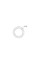
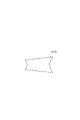
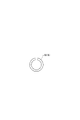
本実施形態では、基準画像8として、図10に示す第1基準画像81、図11に示す第2基準画像82、図12に示す第3基準画像83が用意される。第1基準画像81は、大端部91の画像である。第2基準画像82は、連結部93の画像である。第3基準画像83は、小端部92の画像である。
Further, the reference image 8 is stored in advance in the storage unit 32 of the control unit 3. The reference image 8 is an image that serves as a reference for determining the quality of the appearance of the inspection target area 94. Further, the reference image 8 is an image obtained based on the design value of the work 9 (work 9A), that is, the CAD data.
In the present embodiment, as the reference image 8, the first reference image 81 shown in FIG. 10, the second reference image 82 shown in FIG. 11, and the third reference image 83 shown in FIG. 12 are prepared. The first reference image 81 is an image of the large end portion 91. The second reference image 82 is an image of the connecting portion 93. The third reference image 83 is an image of the small end portion 92.

検査対象領域94が大端部91の場合、当該大端部91の外観の良否判断には、第1基準画像81が用いられる。
なお、図13に示すように、検査対象領域94が連結部93の場合、当該連結部93の外観の良否判断には、第2基準画像82が用いられる。
また、図14に示すように、検査対象領域94が小端部92の場合、当該小端部92の外観の良否判断には、第3基準画像83が用いられる。
When the inspection target area 94 is the large end portion 91, the first reference image 81 is used to determine the quality of the appearance of the large end portion 91.
As shown in FIG. 13, when the inspection target area 94 is the connecting portion 93, the second reference image 82 is used to determine the quality of the appearance of the connecting portion 93.
Further, as shown in FIG. 14, when the inspection target area 94 is the small end portion 92, the third reference image 83 is used to determine the quality of the appearance of the small end portion 92.

画像処理部33は、基準画像8と検査対象画像71との縮尺を合わせる処理を行う。ここで、「縮尺を合わせる処理」とは、単位長さ(実長さ)当たりのスキャン点データ(点群データ)を合わせることを言う。具体的には、画像処理部33は、基準画像8をワーク9の実寸の大きさに対応する第1対応画像とし、検査対象画像71をワーク9の実寸の大きさに対応する第2対応画像とする処理を行う。これにより、後述する判断部34で、基準画像8と検査対象画像71と比較する際、第1対応画像と第2対応画像とを用いれば、基準画像8と検査対象画像71とを同スケールで比較することができる。よって、検査対象領域94に対する良否判断を正確に行うことができる。
また、ワーク9に損傷がある場合、検査対象画像71に対する縮尺の程度によっては、検査対象画像71から損傷が消失するおそれがあるが、画像処理部33では、損傷を強調する処理を行うことができる。これにより、判断部34では、損傷があるワーク9をワーク9Bとして判断することができる。
The image processing unit 33 performs processing for adjusting the scale of the reference image 8 and the inspection target image 71. Here, the "process of adjusting the scale" means to match the scan point data (point cloud data) per unit length (actual length). Specifically, the image processing unit 33 uses the reference image 8 as the first corresponding image corresponding to the actual size of the work 9, and the inspection target image 71 as the second corresponding image corresponding to the actual size of the work 9. Perform the processing. As a result, when the reference image 8 and the inspection target image 71 are compared with each other by the determination unit 34 described later, if the first corresponding image and the second corresponding image are used, the reference image 8 and the inspection target image 71 are on the same scale. Can be compared. Therefore, it is possible to accurately determine the quality of the inspection target area 94.
Further, when the work 9 is damaged, the damage may disappear from the inspection target image 71 depending on the scale of the inspection target image 71, but the image processing unit 33 may perform a process of emphasizing the damage. can. As a result, the determination unit 34 can determine the damaged work 9 as the work 9B.

判断部34は、第1検査および第2検査が行われる際、まず、抽出した検査対象画像71を取り込む。これにより、検査対象領域94以外を含むワーク9の全体の画像7を取り込む場合に比べて、判断部34で処理するスキャン点データを、例えば60%以下に低減することができ、よって、検査時間の短縮が可能となる。
次いで、判断部34は、例えばテンプレートマッチングにより、基準画像8と検査対象画像71とを比較して、良否判断を行う。例えば、基準画像8と検査対象画像71との一致数が閾値を越えた場合には、検査対象領域94の外観が「良」と判断され、閾値以下の場合には、検査対象領域94の外観が「不良」と判断される。
When the first inspection and the second inspection are performed, the determination unit 34 first captures the extracted inspection target image 71. As a result, the scan point data processed by the determination unit 34 can be reduced to, for example, 60% or less as compared with the case where the entire image 7 of the work 9 including the area other than the inspection target area 94 is captured, and thus the inspection time can be reduced. Can be shortened.
Next, the determination unit 34 compares the reference image 8 with the inspection target image 71 by, for example, template matching, and makes a pass / fail determination. For example, when the number of matches between the reference image 8 and the inspection target image 71 exceeds the threshold value, the appearance of the inspection target area 94 is determined to be “good”, and when the number is equal to or less than the threshold value, the appearance of the inspection target area 94 is determined. Is judged to be "bad".

また、判断部34は、各検査対象領域94に対して、良否判断を行う。すなわち、判断部34は、大端部91を検査対象領域94に設定した場合の大端部91に対する良否判断と、連結部93を検査対象領域94に設定した場合の連結部93に対する良否判断と、小端部92を検査対象領域94に設定した場合の小端部92に対する良否判断とを行う。これにより、ワーク9の全体に対する外観の良否判断を過不足なく行うことができる。
なお、外観検査装置1は、検査対象領域94ごとに、例えば閾値等の検査条件を変更することもできる。
In addition, the determination unit 34 makes a pass / fail determination for each inspection target area 94. That is, the determination unit 34 determines the quality of the large end portion 91 when the large end portion 91 is set in the inspection target area 94, and determines the quality of the connection unit 93 when the connection unit 93 is set in the inspection target area 94. , When the small end portion 92 is set in the inspection target area 94, the quality of the small end portion 92 is judged. As a result, it is possible to judge the quality of the appearance of the entire work 9 without excess or deficiency.
The visual inspection device 1 can also change inspection conditions such as a threshold value for each inspection target area 94.

そして、判断部34は、全(複数の)検査対象領域94のうち、少なくとも1つの検査対象領域94に対する良否判断において否と判断した場合には、ワーク9を不良品と判断する。これにより、不良品を高精度に検出することができる。
また、報知部6は、良否判断において否と判断された検査対象領域94を報知することができる。これにより、損傷が生じているのはどこの部分であるのかを把握ことができる。
なお、画像処理部33または判断部34は、各受光部24(受光ユニット22)で各波長の光LBを受光した後、信号処理上、または、当該受光部24で特定の波長に対応した検査対象画像71を抽出することもできる。これにより、波長を特定した分、判断部34で処理する検査対象画像71のスキャン点データを低減して、検査時間の短縮に寄与する。
Then, when the determination unit 34 determines whether or not the quality of at least one inspection target area 94 among all (plural) inspection target areas 94 is good or bad, the determination unit 34 determines that the work 9 is a defective product. As a result, defective products can be detected with high accuracy.
In addition, the notification unit 6 can notify the inspection target area 94 determined to be negative in the quality determination. This makes it possible to know where the damage is occurring.
The image processing unit 33 or the determination unit 34 receives light LB of each wavelength at each light receiving unit 24 (light receiving unit 22), and then performs signal processing or an inspection corresponding to a specific wavelength at the light receiving unit 24. The target image 71 can also be extracted. As a result, the scan point data of the inspection target image 71 processed by the determination unit 34 is reduced by the amount of specifying the wavelength, which contributes to shortening the inspection time.

次に、ワーク9に対する良不良を判断するプログラムについて、図15、図16に示すフローチャートに基づいて説明する。なお、ワーク9に対する良不良を判断するプログラムは、制御部3の記憶部32に予め記憶され、CPU31で実行される。
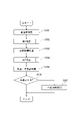
まず、搬送部4を作動させて(ステップS101)、ワーク9を搬送する。
次いで、第1検査を行う(ステップS102)。ステップS102は、サブルーチンである(図16参照)。
Next, a program for determining the quality of the work 9 will be described with reference to the flowcharts shown in FIGS. 15 and 16. The program for determining the quality of the work 9 is stored in advance in the storage unit 32 of the control unit 3 and executed by the CPU 31.
First, the transport unit 4 is operated (step S101) to transport the work 9.
Next, the first inspection is performed (step S102). Step S102 is a subroutine (see FIG. 16).

次いで、反転機構5を作動させて(ステップS103)、ワーク9の表裏を反転させる。
次いで、第2検査を行う(ステップS104)。ステップS104は、サブルーチンである(図16参照)。
次いで、第1検査および第2検査の検査結果に基づいて、ワーク9が良品であるか、または、不良品であるかを判断する(ステップS105)。ステップS105での判断の結果、「ワーク9を良品とする」ことができれば、プログラムを終了する。一方、ステップS105での判断の結果、「ワーク9を良品とする」ことができない場合には、ワーク9の不良個所、すなわち、損傷が生じているのはどこの部分であるのかを、報知部6により報知して、プログラムを終了する。
Next, the reversing mechanism 5 is operated (step S103) to invert the front and back of the work 9.
Then, a second inspection is performed (step S104). Step S104 is a subroutine (see FIG. 16).
Next, it is determined whether the work 9 is a non-defective product or a defective product based on the inspection results of the first inspection and the second inspection (step S105). As a result of the determination in step S105, if "work 9 can be regarded as a non-defective product", the program is terminated. On the other hand, as a result of the determination in step S105, when it is not possible to "make the work 9 a non-defective product", the notification unit informs the defective part of the work 9, that is, the part where the damage is caused. Notify by 6 and terminate the program.

また、ステップS102とステップS104とは、同じステップを有するサブルーチンである(図16参照)。
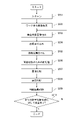
サブルーチンでは、まず、光学ユニット2により、ワーク9全体をスキャンして、撮像する(ステップS201)。
次いで、画像処理部33がワーク9全体の画像7を生成するとともに(ステップS202)、判断部34が画像7から検査対象画像71を抽出する(ステップS203)。
Further, step S102 and step S104 are subroutines having the same step (see FIG. 16).
In the subroutine, first, the optical unit 2 scans the entire work 9 and captures an image (step S201).
Next, the image processing unit 33 generates an image 7 of the entire work 9 (step S202), and the determination unit 34 extracts the inspection target image 71 from the image 7 (step S203).

次いで、判断部34が検査対象画像71を取り込んだ後(ステップS204)、画像処理部33は、基準画像8と検査対象画像71との位置合わせを行って(ステップS205)、当該基準画像8と検査対象画像71とのスケール(縮尺)を合わせる処理(画像比較のための前処理)を行う(ステップS206)。
次いで、判断部34は、基準画像8(第1対応画像)と検査対象画像71(第2対応画像)とを比較して(ステップS207)、検査対象領域94の外観に対する良否を判断する(ステップS208)。
Next, after the determination unit 34 captures the inspection target image 71 (step S204), the image processing unit 33 aligns the reference image 8 and the inspection target image 71 (step S205) with the reference image 8. A process of matching the scale (scale) with the image to be inspected 71 (preprocessing for image comparison) is performed (step S206).
Next, the determination unit 34 compares the reference image 8 (first corresponding image) with the inspection target image 71 (second corresponding image) (step S207), and determines whether the inspection target area 94 is good or bad with respect to the appearance (step). S208).

次いで、判断部34は、ステップS208での判断結果を記憶部32に記憶させる(ステップS209)。
次いで、判断部34は、全検査対象領域94に対して検査(第1検査または第2検査)が終了したか否かを判断する(ステップS210)。
ステップS210での判断の結果、検査が終了した場合には、サブルーチンを終了し、検査が終了していない場合には、ステップS203に戻り、以降のステップを順次実行する。
以上のようなプログラムにより、ワーク9に対する良不良の判断を迅速かつ正確に行うことができる。
Next, the determination unit 34 stores the determination result in step S208 in the storage unit 32 (step S209).
Next, the determination unit 34 determines whether or not the inspection (first inspection or second inspection) has been completed for the entire inspection target area 94 (step S210).
As a result of the determination in step S210, if the inspection is completed, the subroutine is terminated, and if the inspection is not completed, the process returns to step S203 and the subsequent steps are sequentially executed.
With the above program, it is possible to quickly and accurately judge whether the work 9 is good or bad.

また、スケール(縮尺)を合わせる処理(平滑化処理)を行う利点としては、以下の利点もある。
実際に製造されたワーク9の寸法は、寸法公差を含めた外形に仕上がるため、現物のワーク9の画像7と、設計値に基づいて得られた基準画像8、すなわち、寸法公差を含めていない基準画像8とでは、完全に一致することはなく、ワーク9が全て不良品として判断されてしまうおそれがある。そこで、外観検査装置1では、画像7と基準画像8との差を解消するために、スケールを合わせる処理が行われる。これにより、検査時間の短縮を図ることができる。
Further, as an advantage of performing the process of adjusting the scale (scale) (smoothing process), there are also the following advantages.
Since the dimensions of the actually manufactured work 9 are finished in the outer shape including the dimensional tolerance, the image 7 of the actual work 9 and the reference image 8 obtained based on the design value, that is, the dimensional tolerance is not included. It does not completely match the reference image 8, and there is a risk that all the works 9 will be judged as defective products. Therefore, in the visual inspection apparatus 1, a process of adjusting the scale is performed in order to eliminate the difference between the image 7 and the reference image 8. As a result, the inspection time can be shortened.

以上、本発明の外観検査装置を図示の実施形態について説明したが、本発明は、これに限定されるものではなく、外観検査装置を構成する各部は、同様の機能を発揮し得る任意の構成のものと置換することができる。また、任意の構成物が付加されていてもよい。
また、光学ユニット2の配置態様は、搬送方向上流側と下流側とで、それぞれ、前記実施形態では2行3列に配置されるが、これに限定されず、例えば、2行1列であってもよいし、2行2列であってもよい。また、各光学ユニット2の配置箇所については、平面視でベルト41と重なる位置であればよい。
Although the visual inspection apparatus of the present invention has been described above with respect to the illustrated embodiment, the present invention is not limited thereto, and each part constituting the visual inspection apparatus may have any configuration capable of exhibiting the same function. Can be replaced with one. Further, any component may be added.
Further, the arrangement mode of the optical unit 2 is arranged on the upstream side and the downstream side in the transport direction in 2 rows and 3 columns, respectively, but is not limited to this, and is, for example, 2 rows and 1 column. It may be 2 rows and 2 columns. Further, the arrangement location of each optical unit 2 may be a position that overlaps with the belt 41 in a plan view.

1…外観検査装置、2…光学ユニット、2R…光学ユニット、2G…光学ユニット、2B…光学ユニット、21…光照射ユニット、22…受光ユニット、23…光照射部、24…受光部、3…制御部、31…CPU、32…記憶部、33…画像処理部、34…判断部、4…搬送部、41…ベルト、5…反転機構、6…報知部、7…画像(全体画像)、71…検査対象画、8…基準画像、81…第1基準画像、82…第2基準画像、83…第3基準画像、9…ワーク、9A…ワーク、9B…ワーク、91…大端部、92…小端部、93…連結部、94…検査対象領域、95…欠損部、10A…第1カバー、10B…第1カバー、LB…光、LB’…反射光、O41…中心線、O52…軸、S101~S107、S201~S210…ステップ、θ…角度(仰角)

1 ... Visual inspection device, 2 ... Optical unit, 2R ... Optical unit, 2G ... Optical unit, 2B ... Optical unit, 21 ... Light irradiation unit, 22 ... Light receiving unit, 23 ... Light irradiation unit, 24 ... Light receiving unit, 3 ... Control unit, 31 ... CPU, 32 ... Storage unit, 33 ... Image processing unit, 34 ... Judgment unit, 4 ... Transport unit, 41 ... Belt, 5 ... Inversion mechanism, 6 ... Notification unit, 7 ... Image (overall image), 71 ... Inspection target image, 8 ... Reference image, 81 ... First reference image, 82 ... Second reference image, 83 ... Third reference image, 9 ... Work, 9A ... Work, 9B ... Work, 91 ... Large end, 92 ... Small end part, 93 ... Connecting part, 94 ... Inspection target area, 95 ... Defect part, 10A ... First cover, 10B ... First cover, LB ... Light, LB'... Reflected light, O41 ... Center line, O52 ... Axis, S101 to S107, S201 to S210 ... Step, θ ... Angle (elevation angle)

Claims (14)

ワークの外観を検査する外観検査装置であって、
前記ワークに向けて光を照射する光照射ユニットと、
前記光照射ユニットからの前記光が前記ワークで反射した反射光を受光する受光ユニットと、
前記受光ユニットでの受光結果に基づいて前記ワーク全体の画像を生成する画像処理部と、
前記ワーク全体のうちの検査対象となる検査対象領域の検査対象画像を抽出し、該検査対象画像を取り込んで、前記検査対象領域の外観の良否判断の基準となる基準画像と、前記検査対象画像とを比較して、前記良否判断を行う判断部とを備えることを特徴とする外観検査装置。
It is a visual inspection device that inspects the appearance of the work.
A light irradiation unit that irradiates light toward the work,
A light receiving unit that receives the reflected light reflected by the work from the light from the light irradiation unit, and a light receiving unit.
An image processing unit that generates an image of the entire work based on the light receiving result of the light receiving unit, and an image processing unit.
An inspection target image of an inspection target area to be inspected in the entire work is extracted, the inspection target image is taken in, a reference image used as a reference for judging the quality of the appearance of the inspection target area, and the inspection target image. A visual inspection apparatus comprising a determination unit for determining the quality of the image in comparison with the above.
前記光照射ユニットは、前記光として、レーザ光を照射する請求項1に記載の外観検査装置。 The visual inspection device according to claim 1, wherein the light irradiation unit irradiates a laser beam as the light. 前記ワークを搬送する搬送部を備え、
前記光照射ユニットは、前記レーザ光を前記ワークの搬送方向と交差する方向に沿ったライン状に照射する請求項2に記載の外観検査装置。
A transport unit for transporting the work is provided.
The visual inspection device according to claim 2, wherein the light irradiation unit irradiates the laser beam in a line shape along a direction intersecting the transport direction of the work.
前記光照射ユニットは、互いに波長が異なる前記光をそれぞれ照射する複数の光照射部を有し、
前記画像処理部は、前記受光ユニットで各前記波長の光を受光した後、信号処理上、または、前記受光ユニットで特定の波長に対応した前記検査対象画像を抽出する請求項1~3のいずれか1項に記載の外観検査装置。
The light irradiation unit has a plurality of light irradiation units that irradiate the light having different wavelengths from each other.
Any of claims 1 to 3, wherein the image processing unit receives light of each wavelength by the light receiving unit, and then extracts the image to be inspected corresponding to a specific wavelength in signal processing or by the light receiving unit. The visual inspection apparatus according to item 1.
前記光照射ユニットは、互いに波長が異なる前記光をそれぞれ照射する複数の光照射部を有し、
前記受光ユニットは、各前記光照射部からの前記波長が異なる光を個別に受光する複数の受光部を有する請求項1~4のいずれか1項に記載の外観検査装置。
The light irradiation unit has a plurality of light irradiation units that irradiate the light having different wavelengths from each other.
The visual inspection apparatus according to any one of claims 1 to 4, wherein the light receiving unit has a plurality of light receiving units that individually receive light from each light irradiation unit having different wavelengths.
前記ワークを搬送する搬送部を備え、
前記複数の光照射部は、前記ワークの搬送方向と交差する方向に沿って設けられる請求項5に記載の外観検査装置。
A transport unit for transporting the work is provided.
The visual inspection device according to claim 5, wherein the plurality of light irradiation units are provided along a direction intersecting the transport direction of the work.
前記ワークを搬送する搬送部を備え、
前記光照射ユニットは、前記ワークの搬送方向に沿って設けられた少なくとも2つの光照射部を有し、
前記2つの光照射部のうち、前記搬送方向上流側に設けられた前記光照射部は、前記搬送方向上流側から下流側に向かって前記光を照射し、前記搬送方向下流側に設けられた前記光照射部は、前記搬送方向下流側から上流側に向かって前記光を照射する請求項1~6のいずれか1項に記載の外観検査装置。
A transport unit for transporting the work is provided.
The light irradiation unit has at least two light irradiation units provided along the transport direction of the work.
Of the two light irradiation units, the light irradiation unit provided on the upstream side in the transport direction irradiates the light from the upstream side in the transport direction toward the downstream side, and is provided on the downstream side in the transport direction. The visual inspection apparatus according to any one of claims 1 to 6, wherein the light irradiation unit irradiates the light from the downstream side to the upstream side in the transport direction.
前記光照射ユニットと前記受光ユニットとは、前記ワークとの距離を測定するレーザ測長器を構成する請求項1~7のいずれか1項に記載の外観検査装置。 The visual inspection apparatus according to any one of claims 1 to 7, wherein the light irradiation unit and the light receiving unit constitute a laser length measuring device that measures a distance between the work and the work. 前記ワークは、互いに位置が異なる複数の前記検査対象領域を有し、
前記判断部は、各前記検査対象領域に対して、前記良否判断を行う請求項1~8のいずれか1項に記載の外観検査装置。
The work has a plurality of the inspection target areas having different positions from each other.
The visual inspection apparatus according to any one of claims 1 to 8, wherein the determination unit determines whether or not the inspection target area is good or bad.
前記判断部は、複数の前記検査対象領域のうち、少なくとも1つの前記検査対象領域に対する前記良否判断において否と判断した場合には、前記ワークを不良品と判断する請求項9に記載の外観検査装置。 The visual inspection according to claim 9, wherein when the determination unit determines whether or not the work is defective in the quality determination for at least one of the inspection target areas among the plurality of inspection target areas. Device. 前記良否判断において否と判断された前記検査対象領域を報知する報知部を備える請求項10に記載の外観検査装置。 The visual inspection apparatus according to claim 10, further comprising a notification unit for notifying the inspection target area determined to be negative in the quality determination. 前記画像処理部は、前記基準画像と前記検査対象画像との縮尺を合わせる処理を行う請求項1~11のいずれか1項に記載の外観検査装置。 The visual inspection apparatus according to any one of claims 1 to 11, wherein the image processing unit performs a process of adjusting the scale of the reference image and the inspection target image. 前記基準画像は、前記ワークの設計値に基づいて得られた画像であり、
前記画像処理部は、前記基準画像を前記ワークの実寸の大きさに対応する第1対応画像とし、前記検査対象画像を前記ワークの実寸の大きさに対応する第2対応画像とする処理を行い、
前記判断部は、前記第1対応画像と前記第2対応画像とを比較して、前記良否判断を行う請求項1~12のいずれか1項に記載の外観検査装置。
The reference image is an image obtained based on the design value of the work.
The image processing unit performs processing to make the reference image a first corresponding image corresponding to the actual size of the work and the inspection target image to be a second corresponding image corresponding to the actual size of the work. ,
The visual inspection apparatus according to any one of claims 1 to 12, wherein the determination unit compares the first corresponding image with the second corresponding image and makes a quality determination.
前記ワークを表裏反転させる反転機構を備え、
前記ワークの表側に対する外観検査と、裏側に対する外観検査と行う請求項1~13のいずれか1項に記載の外観検査装置。

It is equipped with an inversion mechanism that inverts the work upside down.
The visual inspection apparatus according to any one of claims 1 to 13, wherein the visual inspection on the front side of the work and the visual inspection on the back side are performed.

JP2020165795A 2020-09-30 2020-09-30 Visual Inspection Equipment Active JP7593034B2 (en)

Priority Applications (1)

Application Number Priority Date Filing Date Title
JP2020165795A JP7593034B2 (en) 2020-09-30 2020-09-30 Visual Inspection Equipment

Applications Claiming Priority (1)

Application Number Priority Date Filing Date Title
JP2020165795A JP7593034B2 (en) 2020-09-30 2020-09-30 Visual Inspection Equipment

Publications (2)

Publication Number Publication Date
JP2022057504A true JP2022057504A (en) 2022-04-11
JP7593034B2 JP7593034B2 (en) 2024-12-03

Family

ID=81110210

Family Applications (1)

Application Number Title Priority Date Filing Date
JP2020165795A Active JP7593034B2 (en) 2020-09-30 2020-09-30 Visual Inspection Equipment

Country Status (1)

Country Link
JP (1) JP7593034B2 (en)

Cited By (2)

* Cited by examiner, † Cited by third party
Publication number Priority date Publication date Assignee Title
WO2023188889A1 (en) 2022-03-30 2023-10-05 株式会社神戸製鋼所 Welding control method for automatic welding, control device, welding system, program, and welding method
JP2024156288A (en) * 2023-04-24 2024-11-06 日伸工業株式会社 Processing System

Citations (10)

* Cited by examiner, † Cited by third party
Publication number Priority date Publication date Assignee Title
JPH1068607A (en) * 1996-08-27 1998-03-10 Matsushita Electric Works Ltd Three dimensional shape measuring method
JP2004085204A (en) * 2002-08-22 2004-03-18 Kurabo Ind Ltd Buckling inspection apparatus and method
JP2008064486A (en) * 2006-09-05 2008-03-21 Dainippon Printing Co Ltd Printed matter inspection device, printed matter inspection method
US20080273211A1 (en) * 2005-12-09 2008-11-06 Fraunhofer-Gesellschaft Zur Forderung Der Angewandten Forschung E.V. Apparatus and Method for Measuring the Surface of a Body
JP2017190962A (en) * 2016-04-11 2017-10-19 日本電産トーソク株式会社 Work appearance inspection device and appearance inspection method
JP2018040767A (en) * 2016-09-09 2018-03-15 大日本印刷株式会社 Device and method for supporting visual confirmation
JP2018203418A (en) * 2017-05-31 2018-12-27 ウエブテック株式会社 Workpiece feeding device
EP3470778A1 (en) * 2017-10-13 2019-04-17 Cognex Corporation System and method for field calibration of a vision system imaging two opposite sides of a calibration object
WO2020039567A1 (en) * 2018-08-23 2020-02-27 日本電気株式会社 Object collation device
JP2020051998A (en) * 2018-09-28 2020-04-02 日本電産トーソク株式会社 Product irregularity determination device

Patent Citations (10)

* Cited by examiner, † Cited by third party
Publication number Priority date Publication date Assignee Title
JPH1068607A (en) * 1996-08-27 1998-03-10 Matsushita Electric Works Ltd Three dimensional shape measuring method
JP2004085204A (en) * 2002-08-22 2004-03-18 Kurabo Ind Ltd Buckling inspection apparatus and method
US20080273211A1 (en) * 2005-12-09 2008-11-06 Fraunhofer-Gesellschaft Zur Forderung Der Angewandten Forschung E.V. Apparatus and Method for Measuring the Surface of a Body
JP2008064486A (en) * 2006-09-05 2008-03-21 Dainippon Printing Co Ltd Printed matter inspection device, printed matter inspection method
JP2017190962A (en) * 2016-04-11 2017-10-19 日本電産トーソク株式会社 Work appearance inspection device and appearance inspection method
JP2018040767A (en) * 2016-09-09 2018-03-15 大日本印刷株式会社 Device and method for supporting visual confirmation
JP2018203418A (en) * 2017-05-31 2018-12-27 ウエブテック株式会社 Workpiece feeding device
EP3470778A1 (en) * 2017-10-13 2019-04-17 Cognex Corporation System and method for field calibration of a vision system imaging two opposite sides of a calibration object
WO2020039567A1 (en) * 2018-08-23 2020-02-27 日本電気株式会社 Object collation device
JP2020051998A (en) * 2018-09-28 2020-04-02 日本電産トーソク株式会社 Product irregularity determination device

Cited By (2)

* Cited by examiner, † Cited by third party
Publication number Priority date Publication date Assignee Title
WO2023188889A1 (en) 2022-03-30 2023-10-05 株式会社神戸製鋼所 Welding control method for automatic welding, control device, welding system, program, and welding method
JP2024156288A (en) * 2023-04-24 2024-11-06 日伸工業株式会社 Processing System

Also Published As

Publication number Publication date
JP7593034B2 (en) 2024-12-03

Similar Documents

Publication Publication Date Title
TWI414782B (en) Apparatus and method for use in automatically inspecting and repairing prined circuit boards, and apparutus for use in automatically marking printed circuit boards
JP7566334B2 (en) SYSTEM AND METHOD FOR MEASURING THE SURFACE OF A FORMED GLASS SHEET - Patent application
CN104114992A (en) System and method for controlling the quality of an object
CA3158524A1 (en) Systems and methods for analyzing weld quality
JP2022509137A (en) Detection of machining errors in laser machining systems using deep convolutional neural networks
US20180061718A1 (en) Method of inspecting surface and method of manufacturing semiconductor device
CN113506236B (en) Inspection equipment and welding equipment
JP2022057504A (en) Appearance inspection device
CN112884743A (en) Detection method and device, detection equipment and storage medium
JP2006300663A (en) Defect detection system
US20230282499A1 (en) Apparatus, method and recording medium storing command for inspection
JP4477980B2 (en) X-ray inspection apparatus, X-ray inspection method, and X-ray inspection program
JP2001183124A (en) Method and device for inspecting surface property
KR20250112907A (en) Compensation welding method and joint treatment device for compensation welding
JP2012002605A (en) Defect inspection method of welded surface
JP4056934B2 (en) Spark plug manufacturing method and spark plug manufacturing apparatus
JP2018179812A (en) In-hole inspection apparatus and in-hole inspection method
JP2018054430A (en) Inspection apparatus and measurement trajectory path generation method
JP7557843B2 (en) Laser repair method and laser repair device
TW202109025A (en) Laser review method and laser review device
JP2019070545A (en) Surface inspection apparatus and surface inspection method
KR100750899B1 (en) Inspection equipment for welding defect inspection
JP2018036203A (en) Hole internal inspection device and hole internal inspection method
KR20260012708A (en) Identification and correction of welding paths using optical coherence tomography
JP7435147B2 (en) Glass work inspection method and glass work inspection device

Legal Events

Date Code Title Description
A621 Written request for application examination

Free format text: JAPANESE INTERMEDIATE CODE: A621

Effective date: 20230824

RD03 Notification of appointment of power of attorney

Free format text: JAPANESE INTERMEDIATE CODE: A7423

Effective date: 20230824

A977 Report on retrieval

Free format text: JAPANESE INTERMEDIATE CODE: A971007

Effective date: 20240430

A131 Notification of reasons for refusal

Free format text: JAPANESE INTERMEDIATE CODE: A131

Effective date: 20240514

A521 Request for written amendment filed

Free format text: JAPANESE INTERMEDIATE CODE: A523

Effective date: 20240710

TRDD Decision of grant or rejection written
A01 Written decision to grant a patent or to grant a registration (utility model)

Free format text: JAPANESE INTERMEDIATE CODE: A01

Effective date: 20241022

A61 First payment of annual fees (during grant procedure)

Free format text: JAPANESE INTERMEDIATE CODE: A61

Effective date: 20241104

R150 Certificate of patent or registration of utility model

Ref document number: 7593034

Country of ref document: JP

Free format text: JAPANESE INTERMEDIATE CODE: R150