JP2022111237A - foldable personal vehicle - Google Patents
foldable personal vehicle Download PDFInfo
- Publication number
- JP2022111237A JP2022111237A JP2022092413A JP2022092413A JP2022111237A JP 2022111237 A JP2022111237 A JP 2022111237A JP 2022092413 A JP2022092413 A JP 2022092413A JP 2022092413 A JP2022092413 A JP 2022092413A JP 2022111237 A JP2022111237 A JP 2022111237A
- Authority
- JP
- Japan
- Prior art keywords
- vehicle
- body member
- front bar
- stowed
- orientation
- Prior art date
- Legal status (The legal status is an assumption and is not a legal conclusion. Google has not performed a legal analysis and makes no representation as to the accuracy of the status listed.)
- Granted
Links
Images









Classifications
-
- B—PERFORMING OPERATIONS; TRANSPORTING
- B62—LAND VEHICLES FOR TRAVELLING OTHERWISE THAN ON RAILS
- B62K—CYCLES; CYCLE FRAMES; CYCLE STEERING DEVICES; RIDER-OPERATED TERMINAL CONTROLS SPECIALLY ADAPTED FOR CYCLES; CYCLE AXLE SUSPENSIONS; CYCLE SIDECARS, FORECARS, OR THE LIKE
- B62K5/00—Cycles with handlebars, equipped with three or more main road wheels
-
- B—PERFORMING OPERATIONS; TRANSPORTING
- B62—LAND VEHICLES FOR TRAVELLING OTHERWISE THAN ON RAILS
- B62K—CYCLES; CYCLE FRAMES; CYCLE STEERING DEVICES; RIDER-OPERATED TERMINAL CONTROLS SPECIALLY ADAPTED FOR CYCLES; CYCLE AXLE SUSPENSIONS; CYCLE SIDECARS, FORECARS, OR THE LIKE
- B62K13/00—Cycles convertible to, or transformable into, other types of cycles or land vehicle
- B62K13/04—Cycles convertible to, or transformable into, other types of cycles or land vehicle to a tricycle
-
- B—PERFORMING OPERATIONS; TRANSPORTING
- B62—LAND VEHICLES FOR TRAVELLING OTHERWISE THAN ON RAILS
- B62B—HAND-PROPELLED VEHICLES, e.g. HAND CARTS OR PERAMBULATORS; SLEDGES
- B62B7/00—Carriages for children; Perambulators, e.g. dolls' perambulators
- B62B7/04—Carriages for children; Perambulators, e.g. dolls' perambulators having more than one wheel axis; Steering devices therefor
- B62B7/042—Steering devices
-
- B—PERFORMING OPERATIONS; TRANSPORTING
- B62—LAND VEHICLES FOR TRAVELLING OTHERWISE THAN ON RAILS
- B62B—HAND-PROPELLED VEHICLES, e.g. HAND CARTS OR PERAMBULATORS; SLEDGES
- B62B7/00—Carriages for children; Perambulators, e.g. dolls' perambulators
- B62B7/04—Carriages for children; Perambulators, e.g. dolls' perambulators having more than one wheel axis; Steering devices therefor
- B62B7/044—Carriages for children; Perambulators, e.g. dolls' perambulators having more than one wheel axis; Steering devices therefor three wheeled
-
- B—PERFORMING OPERATIONS; TRANSPORTING
- B62—LAND VEHICLES FOR TRAVELLING OTHERWISE THAN ON RAILS
- B62B—HAND-PROPELLED VEHICLES, e.g. HAND CARTS OR PERAMBULATORS; SLEDGES
- B62B7/00—Carriages for children; Perambulators, e.g. dolls' perambulators
- B62B7/04—Carriages for children; Perambulators, e.g. dolls' perambulators having more than one wheel axis; Steering devices therefor
- B62B7/06—Carriages for children; Perambulators, e.g. dolls' perambulators having more than one wheel axis; Steering devices therefor collapsible or foldable
-
- B—PERFORMING OPERATIONS; TRANSPORTING
- B62—LAND VEHICLES FOR TRAVELLING OTHERWISE THAN ON RAILS
- B62B—HAND-PROPELLED VEHICLES, e.g. HAND CARTS OR PERAMBULATORS; SLEDGES
- B62B7/00—Carriages for children; Perambulators, e.g. dolls' perambulators
- B62B7/04—Carriages for children; Perambulators, e.g. dolls' perambulators having more than one wheel axis; Steering devices therefor
- B62B7/12—Carriages for children; Perambulators, e.g. dolls' perambulators having more than one wheel axis; Steering devices therefor convertible, e.g. into children's furniture or toy
-
- B—PERFORMING OPERATIONS; TRANSPORTING
- B62—LAND VEHICLES FOR TRAVELLING OTHERWISE THAN ON RAILS
- B62K—CYCLES; CYCLE FRAMES; CYCLE STEERING DEVICES; RIDER-OPERATED TERMINAL CONTROLS SPECIALLY ADAPTED FOR CYCLES; CYCLE AXLE SUSPENSIONS; CYCLE SIDECARS, FORECARS, OR THE LIKE
- B62K15/00—Collapsible or foldable cycles
- B62K15/006—Collapsible or foldable cycles the frame being foldable
- B62K15/008—Collapsible or foldable cycles the frame being foldable foldable about 2 or more axes
-
- B—PERFORMING OPERATIONS; TRANSPORTING
- B62—LAND VEHICLES FOR TRAVELLING OTHERWISE THAN ON RAILS
- B62K—CYCLES; CYCLE FRAMES; CYCLE STEERING DEVICES; RIDER-OPERATED TERMINAL CONTROLS SPECIALLY ADAPTED FOR CYCLES; CYCLE AXLE SUSPENSIONS; CYCLE SIDECARS, FORECARS, OR THE LIKE
- B62K9/00—Children's cycles
- B62K9/02—Tricycles
Landscapes
- Engineering & Computer Science (AREA)
- Mechanical Engineering (AREA)
- Chemical & Material Sciences (AREA)
- Combustion & Propulsion (AREA)
- Transportation (AREA)
- Automatic Cycles, And Cycles In General (AREA)
- Motorcycle And Bicycle Frame (AREA)
- Carriages For Children, Sleds, And Other Hand-Operated Vehicles (AREA)
- Vehicle Waterproofing, Decoration, And Sanitation Devices (AREA)
Abstract
Description
本出願の主題は、特に、子供の玩具及び車両製品の分野における、折り畳み可能なパーソナル車両に関する。 The subject matter of the present application relates to foldable personal vehicles, particularly in the field of children's toys and vehicle products.
成人と子供との両方のためのスクーター、車両、及び自転車などの折り畳み可能なパーソナル車両がよく知られている。子供用には、コンパクトな収納及び持ち運びのために車両を折り畳むことができることが時々有益であり得る。 Foldable personal vehicles such as scooters, vehicles, and bicycles for both adults and children are well known. For children, it can sometimes be beneficial to be able to fold the vehicle for compact storage and transport.
分解と折り畳みとの2つの基本原理を中心とした公知の多様なこのような折り畳み可能な車両が存在する。第1のグループの下で、車両は基本部品に分解され、これらは一緒にコンパクトに嵌めることができる。第2のグループの下で、車両のほとんどの部品は、それらの相互接続を維持するが、それらが車両として機能する動作状態と、部品の互いに対する配向及び/又は位置が変化する折り畳まれた収納状態とをとることができる。 There are a variety of such foldable vehicles known that revolve around two basic principles of disassembly and folding. Under the first group, the vehicle is dismantled into basic parts, which can be compactly fitted together. Under the second group, most parts of the vehicle maintain their interconnections, but the operational state in which they function as a vehicle and the folded stowage in which the orientation and/or position of the parts with respect to each other changes. state can be taken.
上記の第2のグループの車両は、例えば、米国特許第6152473号、米国特許第6530589号、及びhttp://www.iimo-life.com/vehicle2_01.htmで説明され、後者は、IIMO Folding Tricycleとして販売される製品である。 Vehicles of the second group mentioned above are for example US Pat. No. 6,152,473, US Pat. No. 6,530,589 and http://www. iimo-life. com/vehicle2_01. htm, the latter being a product marketed as the IIMO Folding Tricycle.
本明細書で開示される主題は、前述の第2のグループの車両を指す。 The subject matter disclosed herein refers to the aforementioned second group of vehicles.
本出願の主題は、動作状態と、極めてコンパクトな形態をとることができる収納状態とを有する、折り畳み可能なパーソナル車両を指す。車両は、その垂直対称面内にあり且つ対称面に垂直な水平基準面を有する、縦軸を有し、収納状態において、対称面と対称面に垂直な垂直面との両方に沿って、その縦軸に沿った方向とこの軸に垂直な方向との両方にそのコンパクトな形態をとる。 The subject of the present application refers to a foldable personal vehicle that has an operational state and a stowed state that allows for a very compact form. The vehicle has a longitudinal axis lying in its vertical plane of symmetry and having a horizontal reference plane perpendicular to the plane of symmetry, and in the stowed state along both the plane of symmetry and a vertical plane perpendicular to the plane of symmetry. It assumes its compact form both along the longitudinal axis and perpendicular to this axis.
本明細書で開示される主題の第1の態様によれば、上記の車両は、
- 座席を保持する上面と、縦軸に沿って互いから離間された前端及び後端と、後端に隣接して配置され、対称面に垂直な方向に互いから離間される後部右側面及び後部左側面とを有する、ボディ部材と、
- フロントバー及びフロントバーに設置された前輪であって、フロントバーは、動作配向及び収納配向をとるべくボディ部材にその前端に隣接して少なくとも間接的にピボット式に連接される、フロントバー及び前輪と、
- それぞれ、後輪を備える脚遠位端と、動作配向及び収納配向をとるべく脚がボディ部材の各後部側面にピボット式に連接される脚近位端とを有する、右後脚及び左後脚であって、脚のうちの少なくとも一方は、脚近位端と脚遠位端との間に接続領域を有する右後脚及び左後脚と、
- フロントバーのその動作配向と収納配向との間のピボットが少なくとも1つの接続部材に後脚をボディ部材の各後部側面に沿ってそれらのそれぞれの動作配向と収納配向との間でピボットさせるようにフロントバーを脚のうちの少なくとも一方の接続領域と少なくとも間接的に接続する、少なくとも1つの接続部材と、
を備えることができる。
According to a first aspect of the presently disclosed subject matter, the vehicle comprises:
- the upper surface holding the seat, the front and rear edges spaced apart from each other along the longitudinal axis, and the rear right and rear sides located adjacent to the rear edge and spaced from each other in a direction perpendicular to the plane of symmetry; a body member having a left side;
- a front bar and a front wheel mounted on the front bar, the front bar being pivotally articulated at least indirectly adjacent a front end thereof to a body member for working and stowed orientations; front wheel;
- a right rear leg and a left rear leg, each having a leg distal end with a rear wheel and a leg proximal end where the leg is pivotally connected to each rear side of the body member for working and stowed orientations; a right hind leg and a left hind leg, at least one of the legs having a connection region between a proximal leg end and a distal leg end;
- so that the pivot of the front bar between its operative and retracted orientations causes the at least one connecting member to pivot the rear legs along each rear side of the body member between their respective operative and retracted orientations; at least one connecting member at least indirectly connecting the front bar to the connecting region of at least one of the legs;
can be provided.
ボディ部材の後部の左右の側面への後脚の近位端のピボット連接と、このような連接のための上記の接続領域(単数又は複数)及び接続部材(単数又は複数)の使用に起因して、車両の後脚は、脚をボディ部材にピボット式に接続するために脚の近位端から離間された位置でそれらの間に延びるどの共通の要素からも自由とすることができる。これは、後脚のピボット角度が、車両の収納状態において、車両の側面図で見られるように各脚の領域の少なくとも大部分がボディ部材の領域の少なくとも大部分と重なる位置を後脚がとることができるほど大きくなることを可能にし、これにより、車両の縦軸に沿った方向とその対称面に沿ったこの軸に垂直な方向との両方におけるこの状態での車両の寸法を本質的に減少させることを可能にする。これは、車両の収納状態において各後脚が少なくともそれらの縦方向の寸法の大部分に沿ってボディ部材と十分に又はほぼ十分に同延とすることができることを意味し、例えば、各後脚は、この端(関連する後輪を含まない)がボディ部材の前端から前方に本質的に突き出ない程度にボディ部材の前端に近いその遠位端を有することができる。この場合、フロントバーは、その収納配向において前輪がボディ部材の前方に配置される種類のものであり、関連する後輪を備える各後脚の少なくとも大部分は、車両の側面図で見られるようにその収納状態においてボディ部材の後端と前輪との間に収容することができ、これにより、この状態でのその縦軸に沿った車両の長さを本質的に減少させることを可能にする。 due to the pivotal articulation of the proximal ends of the hind legs to the left and right lateral sides of the rear of the body member and the use of the aforementioned connecting region(s) and connecting member(s) for such articulation; Thus, the rear legs of the vehicle may be free of any common element extending therebetween at a spaced location from the proximal ends of the legs for pivotally connecting the legs to the body member. This is because the pivot angle of the rear legs is such that, in the stowed condition of the vehicle, the rear legs assume a position in which at least a majority of the area of each leg overlaps at least a majority of the area of the body member as seen in a side view of the vehicle. as large as possible, thereby essentially reducing the dimensions of the vehicle in this condition both along the longitudinal axis of the vehicle and perpendicular to this axis along its plane of symmetry. allow to decrease. This means that in the stowed state of the vehicle each rear leg can be fully or substantially coextensive with the body member along at least the majority of their longitudinal dimension, e.g. may have its distal end proximate to the front end of the body member to the extent that this end (not including the associated rear wheel) protrudes essentially forward from the front end of the body member. In this case, the front bar is of the kind in which the front wheels are arranged in front of the body member in its stowed orientation, and at least a majority of each rear leg with its associated rear wheel is as seen in a side view of the vehicle. In its stowed condition, it can be accommodated between the rear end of the body member and the front wheels, thereby allowing the length of the vehicle along its longitudinal axis in this condition to be substantially reduced. .
上記の観点から、各脚は、ボディ部材の形状及び幅に対して、車両の収納状態においてその側面図で見られるようにそれらが前述のようにそれらの長さの大部分に沿ってだけでなくそれらの高さの大部分に沿っても、すなわち縦軸に垂直な方向に及び対称面に沿って、重なることができるような形状及び幅を有することができ、収納状態でのこの方向の車両の全高を本質的に減少させることを可能にする。 In view of the above, each leg, relative to the shape and width of the body member, is only along most of their length as previously described as seen in a side view thereof in the stowed condition of the vehicle. but also along most of their height, i.e. in the direction perpendicular to the longitudinal axis and along the plane of symmetry, and can have such a shape and width that they can overlap in this direction in the stowed state. Allows the overall height of the vehicle to be substantially reduced.
ボディ部材の対応する後部側面に対する車両の右後脚及び左後脚のそれぞれのピボット連接は、ボディ部材の関連する後部側面から突き出る外側部分を有し、後脚の近位端に形成された貫通チャネル内に自由に受け入れられる、対応する連接軸によって提供することができ、貫通チャネルは後脚の内側側面と外側側面との間に延びる。連接軸は、それぞれ、ボディ部材と一体型に形成する又は連接軸の内側部分によってボディ部材に固定的に設置することができる。いずれにしても、各連接軸の外側部分、すなわちボディ部材の関連する後部側面から突き出る部分は、その近位端で脚の内側側面からチャネルに入り、その連接軸自由端で、脚が連接軸から外れることを防止しながら脚の連接軸を中心としたピボットを可能にするべく脚の外側側面に隣接して配置されるストッパと固定的に係合するように構成することができる。これは、例えば、ストッパを構成しその近位端で脚の外側側面のポケット内に受け入れられる対応するナットにねじ込まれるように構成される連接軸係合端によって行うことができる。 Each pivotal connection of the right rear leg and left rear leg of the vehicle with respect to the corresponding rear side of the body member has an outer portion projecting from the associated rear side of the body member and through-holes formed in the proximal ends of the rear legs. The through channel may be provided by a corresponding articulation shaft freely received within the channel, the through channel extending between the medial side and the lateral side of the rear leg. The articulating shafts may each be integrally formed with the body member or fixedly mounted to the body member by an inner portion of the articulating shaft. In any event, the outer portion of each articulation shaft, i.e. the portion projecting from the associated rear side of the body member, enters the channel at its proximal end from the medial side of the leg, and at its free end of the articulation shaft the leg extends into the articulation shaft. It may be configured to fixedly engage a stop positioned adjacent the lateral side of the leg to allow pivoting of the leg about the articulation axis while preventing disengagement from the leg. This can be done, for example, by an articulating shaft engagement end that constitutes a stopper and is configured to be screwed into a corresponding nut received in a pocket on the outer side of the leg at its proximal end.
代替的に、各連接軸は、後脚と一体型に形成され又はそれに固定的に設置されている状態で、その近位端で対応する後脚の内側側面から突き出ることができ、その対応する後部側面でボディ部材内にピボット式に受け入れることができる。 Alternatively, each articulating shaft, integrally formed with or fixedly attached to the hind leg, can protrude at its proximal end from the medial side surface of the corresponding hind leg, and the corresponding It can be pivotally received in the body member at the rear side.
右連接軸及び左連接軸は、車両の対称面から離間する又は車両の対称面で出会うことができる。後者の場合、2つの連接軸は、ボディ部材内に配置される中央内側部分と前述のようにその後部側面から突き出る2つの横方向外側部分とを有する単一の軸体として形成することができる。 The right articulation axis and the left articulation axis can be spaced from the plane of symmetry of the vehicle or meet at the plane of symmetry of the vehicle. In the latter case, the two articulating shafts may be formed as a single shaft having a central inner portion located within the body member and two lateral outer portions projecting from the rear sides as previously described. .
連接軸のそれぞれの内側部分及び外側部分は、共線とすることができ、単一の後ピボット軸に沿って延びることができ、又はそれらは互いに関して角度をなすことができる。 The respective inner and outer portions of the articulation axis can be collinear, can extend along a single rear pivot axis, or they can be angled with respect to each other.
2つの後脚の連接軸又は少なくともそれらの外側部分は、それらのそれぞれの後ピボット軸に沿ってそれらの間にゼロでない角度をなして延びることができ、各軸は、それぞれの後部右及び左連接点でボディ部材の後部側面と交差する。 The articulation axes of the two hind legs, or at least their lateral portions, may extend along their respective rear pivot axes with a non-zero angle between them, each axis being aligned with the respective rear right and left It intersects the rear side of the body member at the point of articulation.
2つの脚の後ピボット軸は、それぞれ、車両の背面図で見られるときに基準面と鋭角をなすことができる。これは、ピボット軸が基準面に平行な平面内に位置する状態で後脚が有することになる間隔に対して、それらの動作配向において後脚の遠位端間の増加した間隔を得ることを可能にし得る。 The rear pivot axes of the two legs can each make an acute angle with the reference plane when viewed in rear view of the vehicle. This is to obtain increased spacing between the distal ends of the hind legs in their motion orientation relative to the spacing the hind legs would have with the pivot axis lying in a plane parallel to the reference plane. can make it possible.
加えて又は代替的に、右後ピボット軸及び左後ピボット軸のそれぞれは、車両の対称面に関して鋭角に配向することができる。この場合、後脚の動作配向から収納配向への後ピボット軸を中心としたピボットは、それらの遠位端が対称面により近くなること、例えば、対称面からそれらの近位端と同じ又はほぼ同じ程度に離間されることを可能にし、これにより、対称面に垂直な方向の車両の「収納状態」でのコンパクトさを向上させる。 Additionally or alternatively, each of the right rear pivot axis and the left rear pivot axis may be oriented at an acute angle with respect to the plane of symmetry of the vehicle. In this case, the pivot about the posterior pivot axis from the operative orientation of the hind legs to the retracted orientation is such that their distal ends are closer to the plane of symmetry, e.g. It allows them to be spaced to the same extent, which improves the compactness in the "stowed state" of the vehicle in the direction perpendicular to the plane of symmetry.
ピボット軸が対称面及び対称面に垂直な平面と鋭角をなす場合、車両の動作状態では後脚の遠位端間の間隔が増加するにもかかわらず、上述の「収納状態」でのコンパクト性が達成される。 If the pivot axis makes an acute angle with the plane of symmetry and the plane perpendicular to the plane of symmetry, compactness in the above-mentioned "stowed state" despite the increased spacing between the distal ends of the rear legs in the operating state of the vehicle. is achieved.
ボディ部材は、その前部左側面及び前部右側面を備えるボディ前部と、その後部右側面及び後部左側面を備えるボディ後部とを有することができる。前部の左右の側面は、後部の左右の側面よりも対称面の近くに配置することができ、これは対称面に垂直な方向にボディ後部をボディ前部よりも広くすることができることを意味する。 The body member may have a front body portion with a front left side and a front right side thereof, and a body rear portion with a rear right side and a rear left side. The left and right flanks of the front can be placed closer to the plane of symmetry than the left and right flanks of the rear, which means that the rear body can be wider than the front body in a direction perpendicular to the plane of symmetry. do.
加えて、ボディ部材の後部は、ボディ後部の左右の側面の対応する配向によって提供される、その平面図及び背面図のうちの少なくとも1つで見られるように集束する構成を有することができる。この場合、その近位端に隣接する各後脚の内側側面は、ボディ部材の対応する後部側面と同様に同延となるように配向することができ、これらの表面は車両の収納状態と動作状態との両方において互いに密接に接触することができる。例えば、その近位端での接触するボディ部材の後部側面と後脚の内側側面との左右の対のそれぞれの配向は、左右のピボット軸の上記の鋭角のうちの一方又は両方を提供するような配向とすることができ、この場合、これらの軸は、対応する接触面に垂直とすることができる。 Additionally, the rear portion of the body member can have a converging configuration as seen in at least one of its top and rear views provided by the corresponding orientation of the left and right sides of the body rear portion. In this case, the medial side of each rear leg adjacent its proximal end may be oriented so as to be coextensive as well as the corresponding rear side of the body member, these surfaces being aligned with the stowed condition and operation of the vehicle. can be in intimate contact with each other in both states. For example, the orientation of each left and right pair of the posterior sides of the contacting body members and the medial sides of the hind legs at their proximal ends to provide one or both of the above acute angles of the left and right pivot axes. orientation, where these axes can be perpendicular to the corresponding contact surfaces.
ボディ部材は、一体型の形態とすることができ、又はいくつかの要素から組み立てることができる。例えば、これらの要素は、それらのリムが車両の対称面で出会い、且つそれらの間に少なくとも部分的に中空の内部を画定するように組み立てられるボディ右部及びボディ左部を含むことができる。 The body member may be of unitary form or may be assembled from several elements. For example, these elements may include a right body portion and a left body portion assembled such that their rims meet at a plane of symmetry of the vehicle and define an at least partially hollow interior therebetween.
フロントバーは、前輪に関連したフロントバーの前輪端とハンドルバーに関連したハンドルバー端との間でフロントバー軸に沿って延びることができる。フロントバー軸は、車両の収納状態においてとられるフロントバーの収納配向にあるときよりも、車両の動作状態においてとられるバーの動作配向にあるときに、車両の縦軸と本質的により大きい角度をなすことができる。具体的には、この構成は、フロントバーの収納配向において、フロントバー軸が縦軸と25度を超えない、より具体的には20度を超えない、さらにより具体的には15度を超えない角度をなすようなものとすることができる。随意的に、フロントバー軸は、車両の収納状態において縦軸に平行又はほぼ平行とすることができる。 The front bar may extend along a front bar axis between a front wheel end of the front bar associated with the front wheel and a handlebar end associated with the handlebar. The front bar axis makes a substantially greater angle with the longitudinal axis of the vehicle when in the operational orientation of the bars taken in the vehicle's operating condition than when in the stowed orientation of the front bars taken in the stored condition of the vehicle. It can be done. Specifically, the configuration is such that in the stowed orientation of the front bar, the front bar axis does not exceed 25 degrees, more specifically does not exceed 20 degrees, and even more specifically does not exceed 15 degrees with the longitudinal axis. can be such that they form a non-linear angle. Optionally, the front bar axis can be parallel or nearly parallel to the longitudinal axis in the stowed condition of the vehicle.
フロントバーは、それによりフロントバーが前ピボット軸を中心としてボディ部材の前端にピボット式に連接される連接部材をさらに備える、フロント組立体の一部を構成することができ、連接部材は接続部材(単数又は複数)に接続される。車両の動作状態におけるフロントバーの動作配向においてフロントバーがボディ部材の前方に配置され、車両の収納状態におけるその収納配向においてフロントバーがフロントバーの長さの少なくとも大部分に沿ってボディ部材の上面よりも上に配置され且つボディ部材の上面に沿って延びるように、前ピボット軸をフロントバー軸から間隔をおいて配置することができる。 The front bar may form part of a front assembly further comprising a connecting member whereby the front bar is pivotally connected to the front end of the body member about the front pivot axis, the connecting member being the connecting member connected to (singular or plural); The front bar is positioned in front of the body member in its operating orientation in the vehicle's operating state, and in its stowed orientation in the vehicle's stowed state the front bar extends along at least a majority of the length of the front bar on the upper surface of the body member. A front pivot axis may be spaced from the front bar axis so as to be positioned above and extend along the upper surface of the body member.
上記の構成により、フロントバーは、車両の収納状態において、縦軸から上方に、フロントバー自体の任意の点以外の車両の最高点の距離よりも短い距離に離間されるように配向することができる。この最高点は、例えば、車両の収納状態における前輪及び/又は座席の最高点とすることができる。 With the above arrangement, the front bar can be oriented in the stowed condition of the vehicle so that it is spaced upwardly from the longitudinal axis a distance less than the distance of the highest point of the vehicle other than any point on the front bar itself. can. This highest point can be, for example, the highest point of the front wheels and/or the seat in the stowed state of the vehicle.
連接部材は、フロントバーがフロントバー軸を中心として旋回することを可能にする様態でフロントバーを取り囲むフロントバー関連部分と、後脚(単数又は複数)の接続領域(単数又は複数)に取り付けられる端とは反対の端に少なくとも1つの接続部材が取り付けられる後脚関連部分と、連接部材がボディ部材の前端にピボット式に連接されるボディ部材関連部分とを有することができる。 The connecting member is attached to the front bar-related portion surrounding the front bar in a manner that allows the front bar to pivot about the front bar axis, and to the connection region(s) of the rear leg(s). There may be a rear leg associated portion having at least one connecting member attached to the opposite end and a body member associated portion having a connecting member pivotally connected to the front end of the body member.
少なくとも1つの接続部材は、その長さが車両の動作中及び車両の状態が変化されるときに一定に維持されるように、剛性の材料で作製することができる。より具体的には、接続部材は、連接部材によって押されるときに、対応して後脚をそれらの収納配向からそれらの動作配向に押すことができるのに十分な剛性とすることができる。車両は、連接部材をそれぞれの右及び左後脚の接続領域とそれぞれ接続する、右及び左の2つの接続部材を備えることができる。 The at least one connecting member may be made of a rigid material such that its length remains constant during operation of the vehicle and as vehicle conditions change. More specifically, the connecting member may be sufficiently rigid to be able to correspondingly push the hind legs from their stowed orientation to their operational orientation when pushed by the articulating member. The vehicle may comprise two connecting members, right and left, connecting the connecting member with respective connecting regions of the respective right and left rear legs.
車両は、前輪に取り外し可能に設置可能な又はこれと一体に組み立てられるペダルをさらに備えることができる。 The vehicle may further comprise pedals removably attachable to or integrally assembled with the front wheels.
車両は、ボディ部材に沿った座席の位置を調節するようにさらに構成することができる。 The vehicle may be further configured to adjust the position of the seat along the body member.
車両は、座席にいるそのユーザが自分で車両を操縦することを可能にする、又は別の人によって操作される操縦ハンドルを介して車両がその後方から操縦されることを可能にしながらユーザによる操縦を防ぐことを可能にするように構成することができる。この場合、車両は、以下の特徴:
- ハンドルバーの操作によって操縦可能な単一の一体のユニットとして機能するようにその上部と下部を互いに係止すること、及び下部を、上部を含まない別個の操縦機構によって操縦することを可能にし、且つ下部の操縦へのどのような影響も有さずに上部の所望の機能を可能にするように互いから係止解除することができる、フロントバーの一体でない設計と、
- ハンドルバーの操作によってフロントバー又はその上部がフロントバー軸を中心として回転する可能性をなくすべく、少なくともフロントバーの少なくとも上部を車両の動作状態にあるときに移動可能ではない例えばその安全フレームなどの車両の要素に係止するための、フロントバー係止クランプと、
- ボディ部材の後端に設置されたときに回転可能なリア操縦ハンドルと共に用いるための、折り畳み可能なリア操縦機構であって、該機構は、車両を操縦するためにハンドルの操作がフロントバー又はその下部を、フロントバー軸を中心として回転させるようにハンドルをフロントバー又は少なくともその下部と接続するリア操縦機構と、
- 前輪よりも座席により近い場所でボディ部材に少なくとも間接的に固定的に設置可能な、フットレストであって、この場所は、連接部材とすることができ、より具体的には、そのボディ部材関連部分又はその後脚関連部分とすることができ、又はこれらの2つの部分間とすることができ、フットレストは、前輪から取り外されるときに上記のペダルによって構成することができるフットレストと、
のうちの1つ又は複数を有することができる。
The vehicle can be steered by the user while allowing the user in the seat to steer the vehicle himself or to allow the vehicle to be steered from behind via a steering wheel operated by another person. can be configured to prevent In this case, the vehicle has the following characteristics:
- allow its upper and lower parts to lock together so as to function as a single integral unit steerable by operation of the handlebars, and the lower part to be steered by a separate steering mechanism that does not include the upper part; and a non-integral design of the front bars that can be unlocked from each other to allow the desired function of the upper portion without any impact on the steering of the lower portion;
- At least the upper part of the front bar is not displaceable when the vehicle is in motion, e.g. its safety frame, in order to eliminate the possibility of the front bar or its upper part rotating about the front bar axis due to manipulation of the handlebars. a front bar locking clamp for locking to a vehicle element of the
- a collapsible rear steering mechanism for use with a rotatable rear steering handle when mounted at the rear end of a body member, the mechanism enabling manipulation of the handle to steer the vehicle from the front bar or a rear steering mechanism connecting the handle with the front bar or at least the lower portion thereof so as to rotate the lower portion about the front bar axis;
- a footrest that can be fixedly mounted at least indirectly on a body member at a location closer to the seat than the front wheels, which location can be an articulation member, more specifically associated with that body member; a footrest, which may be a part or a rear leg-related part, or between these two parts, the footrest being constituted by said pedals when removed from the front wheel;
can have one or more of
車両は、フロントバー下部がその動作配向と収納配向との間でピボットされることを可能にする任意の設計の操縦機構を有することができる。このような設計の一例によれば、操縦機構は、以下の要素:
- フロントバーに固定的に設置された、フロント回転部材と、
- ボディ部材の後端に存在し、ハンドル軸を中心としたハンドルの回転が対応してポートを回転させるようにリア操縦ハンドルを固定的に受け入れるように構成された、リア回転可能ポートと、
- それぞれフロント回転部材とポートとの間に延びる右ケーブル区域及び左ケーブル区域を含み、ポートの異なる方向の回転が左区域又は右区域を引っぱり、このような引っぱりがフロント回転部材、続いて、少なくともフロントバーの下部の回転運動をもたらすようにフロント回転部材及びポートに接続される、少なくとも一対のケーブル区域であって、右ケーブル区域及び左ケーブル区域は、前ピボット軸の近傍の位置で屈曲するように構成される少なくとも一対のケーブル区域と、
を備えることができる。
The vehicle may have any design of steering mechanism that allows the front bar lower portion to be pivoted between its operative and stowed orientations. According to one example of such a design, the steering mechanism includes the following elements:
- a front rotating member fixedly mounted on the front bar;
- a rear rotatable port at the rear end of the body member and configured to fixedly receive the rear steering handle such that rotation of the handle about the handle axis correspondingly rotates the port;
- including a right cable section and a left cable section respectively extending between the front rotating member and the port, wherein rotation of the port in different directions pulls the left section or the right section, such pulling the front rotating member followed by at least At least one pair of cable sections connected to the front rotating member and port to provide rotational movement of the lower portion of the front bar, the right cable section and the left cable section being bent at a location near the front pivot axis. at least one pair of cable segments configured in
can be provided.
右ケーブル区域及び左ケーブル区域は、それらの長さの大部分に沿って車両のボディ部材に沿って及び内部に延びることができる。右ケーブル区域及び左ケーブル区域は、フロント回転部材に及び回転ポートに固定的に取り付けられる1つのケーブルの部品とすることができる。 The right cable section and the left cable section may extend along and into the body member of the vehicle along most of their length. The right cable section and the left cable section may be parts of one cable fixedly attached to the front rotating member and to the rotating port.
本出願の主題の別の態様によれば、概要の項目の第1のパラグラフで概して説明される車両は、
- 座席を保持する上面と、縦軸に沿って互いから離間された前端及び後端と、後端に隣接して配置され、対称面に垂直な方向に互いから離間される後部右側面及び後部左側面とを有する、ボディ部材と、
- フロントバー及びフロントバーに設置された前輪であって、フロントバーは、動作配向及び収納配向をとるべくボディ部材にその前端に隣接して少なくとも間接的にピボット式に連接される、フロントバー及び前輪と、
- それぞれ脚近位端と後輪が設置される脚遠位端とを有する、右後脚及び左後脚と、
- 対応する右後脚又は左後脚が動作配向及び収納配向をとるべくボディ部材の各後部側面にそれを中心としてピボット式に連接される、右後ピボット軸及び左後ピボット軸であって、後ピボット軸のそれぞれは、後脚の動作配向から収納配向への後ピボット軸を中心としたピボットが、それらの遠位端が対称面により近くなること、例えば、それらの動作配向にあるときよりもそれらの収納配向において対称面からより小さい程度に離間されること、随意的に、対称面からそれらの近位端と同じ又はほぼ同じ程度に離間されることを可能にするように、その平面図において車両の対称面に鋭角に配向される右後ピボット軸及び左後ピボット軸と、
を備えることができる。
According to another aspect of the present subject matter, a vehicle as generally described in the first paragraph of the general section includes:
- the upper surface holding the seat, the front and rear edges spaced apart from each other along the longitudinal axis, and the rear right and rear sides located adjacent to the rear edge and spaced from each other in a direction perpendicular to the plane of symmetry; a body member having a left side;
- a front bar and a front wheel mounted on the front bar, the front bar being pivotally articulated at least indirectly adjacent a front end thereof to a body member for working and stowed orientations; front wheel;
- a right hind leg and a left hind leg, each having a proximal leg end and a distal leg end on which the rear wheel is mounted;
- a right rear pivot axis and a left rear pivot axis pivotally articulated about each rear side of the body member for a working or retracted orientation with a corresponding right rear leg or left rear leg; Each of the posterior pivot axes pivots about the posterior pivot axis from the operative orientation of the hind legs to the stowed orientation so that their distal ends are closer to the plane of symmetry, e.g., than when in their operative orientation. are spaced from the plane of symmetry in their stowed orientation to a lesser extent, optionally to the same or about the same extent as their proximal ends from the plane of symmetry. a right rear pivot axis and a left rear pivot axis oriented at an acute angle to the plane of symmetry of the vehicle in the figure;
can be provided.
本明細書で開示される主題のこの態様に係る車両は、本明細書で開示される主題の前述した態様に関して上記で特定される特徴のいずれかをその任意の組み合わせで有することができる。 A vehicle according to this aspect of the presently disclosed subject matter may have any of the features identified above with respect to the foregoing aspects of the presently disclosed subject matter, in any combination thereof.
本出願の主題のさらなる態様によれば、概要の項目の第1のパラグラフで概して説明される車両は、
- 座席を保持する上面と、縦軸に沿って互いから離間された前端及び後端と、両方とも後端に隣接して配置され、対称面に垂直な方向に互いから離間される後部右側面及び後部左側面とを備えるボディ部材と、
- フロントバー及びフロントバーに設置された前輪であって、フロントバーは、動作配向及び収納配向をとるべくボディ部材にその前端に隣接して少なくとも間接的にピボット式に連接される、フロントバー及び前輪と、
- それぞれ脚近位端と後輪が設置される脚遠位端とを有する、右後脚及び左後脚と、
- 対応する右後脚又は左後脚が動作配向及び収納配向をとるべくボディ部材の各後部側面にそれを中心としてピボット式に連接される、右後ピボット軸及び左後ピボット軸であって、後ピボット軸のそれぞれは、ピボット軸が基準面に平行な平面内に位置する状態で脚が有することになる間隔に対して、それらの動作配向において後脚の遠位端間の増加した間隔を得るべく、車両の背面図において基準面に対して鋭角に配向される、右後ピボット軸及び左後ピボット軸と、
を備えることができる。
According to a further aspect of the subject matter of the present application, a vehicle as generally described in the first paragraph of the general section includes:
- the upper surface holding the seat, the front and rear edges spaced apart from each other along the longitudinal axis, both located adjacent to the rear edge and the right rear flank spaced apart from each other in a direction perpendicular to the plane of symmetry; and a rear left side surface;
- a front bar and a front wheel mounted on the front bar, the front bar being pivotally articulated at least indirectly adjacent a front end thereof to a body member for working and stowed orientations; front wheel;
- a right hind leg and a left hind leg, each having a proximal leg end and a distal leg end on which the rear wheel is mounted;
- a right rear pivot axis and a left rear pivot axis pivotally articulated about each rear side of the body member for a working or retracted orientation with a corresponding right rear leg or left rear leg; Each of the rear pivot axes provides increased spacing between the distal ends of the rear legs in their motion orientation relative to the spacing the legs would have with the pivot axes lying in a plane parallel to the reference plane. To obtain, a right rear pivot axis and a left rear pivot axis oriented at an acute angle to a reference plane in a rear view of the vehicle;
can be provided.
本明細書で開示される主題のこの態様に係る車両は、本明細書で開示される主題の前述した態様に関して上記で特定される特徴のいずれかをその任意の組み合わせで有することができる。 A vehicle according to this aspect of the presently disclosed subject matter may have any of the features identified above with respect to the foregoing aspects of the presently disclosed subject matter, in any combination thereof.
本出願の主題のさらに別の態様によれば、概要の項目の第1のパラグラフで概して説明される車両は、
- 前部及び後部を有するボディ部材と、
- その動作配向と収納配向との間でピボットされるように、前ピボット軸を介してボディの前部に少なくとも間接的にピボット式に連接され、車両の前輪を保持する、フロントバーと、
- 動作配向及び収納配向をとるべく後ピボット軸を介してそれぞれボディの後部にピボット式に連接され、車両の後輪を保持する、2つの後脚と、
- 車両がその動作状態にあるときにハンドルを用いるためにリア操縦ハンドルを固定的に受け入れるように構成された、回転可能なリア操縦ポートと、
- 車両を操縦するためにその動作状態にあるときにハンドルによるポートの回転が少なくともフロントバーの下部を回転させるように前記ポートをフロントバーと接続する、操縦機構であって、ボディ部材内に少なくとも部分的に延び、フロントバーがその動作配向からその収納配向にピボットされるときに前ピボット軸の近傍で屈曲されるように構成された、少なくとも1つの操縦要素を備える操縦機構と、
を備えることができる。
According to yet another aspect of the present subject matter, a vehicle as generally described in the first paragraph of the Summary Section includes:
- a body member having a front portion and a rear portion;
- a front bar pivotally connected at least indirectly to the front part of the body via a front pivot axis so as to be pivoted between its working and stowed orientations, and holding the front wheels of the vehicle;
- two rear legs, each pivotally connected to the rear part of the body via a rear pivot axis for working and stowed orientations, holding the rear wheels of the vehicle;
- a rotatable rear steering port configured to fixedly receive a rear steering handle for using the steering wheel when the vehicle is in its operational state;
- a steering mechanism connecting the port with the front bar such that rotation of the port by the handle when in its operational state to steer the vehicle rotates at least the lower part of the front bar, the steering mechanism being at least in the body member; a steering mechanism comprising at least one steering element partially extending and configured to bend about the front pivot axis when the front bar is pivoted from its operating orientation to its stowed orientation;
can be provided.
操縦機構は、フロントバーに固定的に設置されたフロント回転部材と、それぞれフロント回転部材とポートとの間に延び、ポートの時計回り又は反時計回りの回転がそれぞれの右区域又は左区域を引っぱり、このような引っぱりがフロント回転部材、続いて、フロントバーの回転運動をもたらすようにフロント回転部材及びポートに接続される、操縦要素を構成する一対の屈曲可能な右ケーブル区域及び左ケーブル区域とをさらに備えることができる。右ケーブル区域及び左ケーブル区域は、ボディ部材内にそれらの長さの大部分に沿って延びることができ、それぞれ前ピボット軸の近傍で屈曲されるように構成される。 The steering mechanism extends between a front rotating member fixedly mounted on the front bar and the respective front rotating member and the port, wherein clockwise or counterclockwise rotation of the port pulls the respective right or left section. , a pair of bendable right and left cable sections forming a steering element connected to the front rotating member and ports such that such tension provides rotational movement of the front rotating member and, in turn, the front bar; can be further provided. The right cable section and the left cable section may extend into the body member along a majority of their length and are each configured to be bent about the forward pivot axis.
本明細書で開示される主題のこの態様に係る車両は、本明細書で開示される主題の前述した態様に関して上記で特定される特徴のいずれかをその任意の組み合わせで有することができる。 A vehicle according to this aspect of the presently disclosed subject matter may have any of the features identified above with respect to the foregoing aspects of the presently disclosed subject matter, in any combination thereof.
本明細書で開示される主題のまたさらなる態様によれば、概要の項目の第1のパラグラフで概して説明される車両は、望まれるときに子供が車両を操縦できないように構成された乳母車へ変換可能とすることができ、車両は、
- 前部及び後部を有するボディ部材と、
- その動作配向と収納配向との間でピボットされるように、前ピボット軸を介してボディの前部に少なくとも間接的にピボット式に連接され、一対のペダルを設置することができる又は一対のペダルが設置される車両の前輪を保持する、フロントバーと、
- 動作配向及び収納配向をとるべく後ピボット軸を介してそれぞれボディの後部にピボット式に連接され、車両の後輪を保持する、2つの後脚と、
を備え、車両は、以下の特徴:
- ハンドルバーの操作によって操縦可能な単一の一体のユニットとして機能するようにその上部と下部を互いに係止すること、及び下部を、上部を含まない別個の操縦機構によって操縦することを可能にし、且つ下部の操縦へのどのような影響も有さずに上部の所望の機能を可能にするように互いから係止解除することができる、フロントバーの一体でない設計と、
- ハンドルバーの操作によってフロントバー又はその上部がフロントバー軸を中心として回転する可能性をなくすべく、少なくともフロントバーの上部を車両の動作状態にあるときに移動可能ではない、例えばその安全フレームなどの車両の要素に係止するための、フロントバー係止クランプと、
- ボディ部材の後端に設置されたときに回転可能なリア操縦ハンドルと共に用いるための、折り畳み可能なリア操縦機構であって、車両を操縦するためにハンドルの操作がフロントバーの下部を、フロントバー軸を中心として回転させるようにハンドルをフロントバーと接続するリア操縦機構と、
- 前輪よりも座席により近い場所でボディ部材に少なくとも間接的に固定的に設置可能なフットレストであって、この場所は、連接部材とすることができ、より具体的には、そのボディ部材関連部分又はその後脚関連部分とすることができ、又はこれらの2つの部分間とすることができ、フットレストは、前輪から取り外されるときにペダルによって構成することができる、フットレストと、
のいずれか1つ、いずれか2つ、いずれか3つ、又はすべてをさらに有する。
According to still further aspects of the presently disclosed subject matter, the vehicle generally described in the first paragraph of the Summary Section converts into a baby carriage configured to prevent a child from steering the vehicle when desired. It is possible that the vehicle
- a body member having a front portion and a rear portion;
- pivotally connected at least indirectly to the front part of the body via a front pivot axis so as to be pivoted between its working and stowed orientations, capable of mounting a pair of pedals or a pair of a front bar holding the front wheels of the vehicle on which the pedals are mounted;
- two rear legs, each pivotally connected to the rear part of the body via a rear pivot axis for working and stowed orientations, holding the rear wheels of the vehicle;
Equipped with the vehicle features the following:
- allow its upper and lower parts to lock together so as to function as a single integral unit steerable by operation of the handlebars, and the lower part to be steered by a separate steering mechanism that does not include the upper part; and a non-integral design of the front bars that can be unlocked from each other to allow the desired function of the upper portion without any impact on the steering of the lower portion;
- At least the upper part of the front bar is not movable when the vehicle is in motion, e.g. its safety frame, in order to eliminate the possibility of the front bar or its upper part rotating about the front bar axis due to manipulation of the handlebars. a front bar locking clamp for locking to a vehicle element of the
- a foldable rear steering mechanism for use with a rotatable rear steering handle when mounted at the rear end of a body member, the operation of the handle to steer the vehicle over the lower portion of the front bar; a rear steering mechanism connecting the handle with the front bar for rotation about the bar axis;
- a footrest that can be fixedly mounted at least indirectly on a body member at a location closer to the seat than the front wheels, which location can be an articulation member, more specifically the body member associated part thereof; a footrest, which may be the leg-related part after, or between these two parts, the footrest being constituted by the pedals when removed from the front wheel;
any one, any two, any three, or all of
本明細書で開示される主題のこの態様に係る車両は、本明細書で開示される主題の前述した態様に関して上記で特定される特徴のいずれかをその任意の組み合わせで有することができる。 A vehicle according to this aspect of the presently disclosed subject matter may have any of the features identified above with respect to the foregoing aspects of the presently disclosed subject matter, in any combination thereof.
本明細書で開示される主題をよりよく理解するため及びこれが実際にどのように実施され得るかを例示するために、ここで実施形態を限定ではない単なる例として添付図を参照しながら説明する。 For a better understanding of the subject matter disclosed herein and to illustrate how this may be implemented in practice, embodiments will now be described, by way of non-limiting example only, with reference to the accompanying figures. .
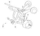
上記に挙げた図面は、それぞれ本明細書の全体を通して、図1A~図3Eに例示された車両1、図4A及び図4Bに例示された車両100、及び図5A~図5Cに例示された車両200を含む「車両」として言及される、子供用のいくつかの三輪車を例示する。車両1、100、及び200のそれぞれは、車両の対称面SP内に位置する縦軸Lを有し、且つ、
- 対称面に垂直な本明細書では基準面RPとして言及される平面に沿った車両に乗ることができる、その動作状態と、
- その縦軸Lが基準面と車両の動作状態においてそれらの間に形成される角度を超えない又は少なくとも本質的に超えない角度LRをなすように車両を基準面RP上に自由に置くことができるその収納状態と、
の間で折り畳み可能である。
Each of the above-listed drawings will be used throughout this specification to refer to the
- its operating state, in which the vehicle can be ridden along a plane perpendicular to the plane of symmetry, referred to herein as reference plane RP;
- the vehicle is free to lay on the reference plane RP such that its longitudinal axis L makes an angle LR which does not exceed, or at least essentially does not exceed, the angle formed between the reference plane and the vehicle in its operational state; The storage state that can be done,
It can be folded between
車両の縦軸、対称面、基準面、及び収納状態は、車両1に関する図面にのみ示され、車両1の説明は、車両100及び200に十分に適用することができる。
The longitudinal axis, plane of symmetry, reference plane and stowed state of the vehicle are only shown in the drawings relating to
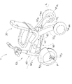
図1Aを参照すると、車両1は、剛性のボディ部材10と、座席部30と、ペダルPを有する前輪WF付きのフロント組立体50と、それぞれ後輪WRR及びWRL付きの右後脚70R及び左後脚70Lと、接続機構90とを備える。これらの後脚及びその後輪は同一の設計を有するので、これらの後脚は図1A以外の図面に単一の参照番号70で表され、その後輪は、以下、WRとして表される。
Referring to FIG. 1A, a
図1B及び図1Gを参照すると、ボディ部材10は、ボディ前端12Fを含むボディ前部11Fと、ボディ後端12Rを含むボディ後部11Rとを備え、前部及び後部は、車両の動作状態と収納状態との両方において一定の相互配置を有する。ボディ部材は、一体型の形態とすることができ、或いは、いくつかの要素で組み立てることができる。
1B and 1G, the
図1Bで見られるように、ボディ部材10は、上方に又は基準面RPから離れる方に面する上面13と、下方に又は基準面RPの方に面する下面14と、ボディ部材の前部の上面と下面との間に延び、ボディ前部11Fを画定する、前部の左右の側面15Fと、ボディ部材の後部の上面と下面との間に延び、後脚70がピボット式に連接されるボディ後部11Rを画定する、後部の左右の側面15Rとを備える。図1Gで最も良く見られるように、ボディ部材10の前部の左右の側面15Fは、後部の左右の側面15Rよりも対称面SPにより近く、これは、ボディ後部11Rがボディ前部11Fよりも対称面SPに垂直な方向により広いことを意味する。
As seen in FIG. 1B, the
図1A及び図1Cで最も良く見られるように、座席部30は、ボディ後部11Rによって少なくとも部分的に支持されるようにボディ部材10の上面13に設置される座席32を備える。座席部は、ボディ後部11Rの上面が座席の領域によって異なる程度に覆われる状態で、ボディ部材に沿った少なくとも2つの異なる位置のうちの1つに設置されるように構成することができる。
As best seen in FIGS. 1A and 1C, the
座席部30は、座席32と一体に組み立てられる又は一体型に形成される固定の背もたれ部35と、折り畳み可能な背もたれ部37とを有する、背もたれ34をさらに備える。背もたれ部37は、車両1の動作状態における背もたれ部37の概して直立した配向と車両の収納状態における背もたれ部37の概して水平な配向との間で、基準面RPに平行な軸XBRを中心としてピボット運動可能であり、固定の座席部分35によって座席32から離間される。加えて、背もたれ部は、車両の動作状態において乗る人/ユーザの背中へのより具合の良い支持を選ぶことを可能にするべく、少なくとも2つの異なる直立位置をとるように構成することができる。
The
座席部30は、この例では、座席32に座っている子供が車両1から落下するのを防ぐことができるその概して水平な動作配向と車両を折り畳むプロセスで用いられる概して垂直な非動作配向との間でピボットする背もたれ部37と同じ軸XBRを中心としてピボットすることができる、随意的な安全フレーム36をさらに備える。安全フレームは、車両に取り外し可能に取り付けることができるように構成することができる。
The
座席は、固定の部分及び/又は安全フレームなしに形成することができ、折り畳み可能な背もたれ部は、それを中心としてピボットすることができる異なる軸を有することができ、この場合、背もたれのピボット軸は、車両の動作状態において安全フレームのピボット軸よりも座席により近く配置される。背もたれは、座席に恒久的にピボット式に設置することができる、剛性の材料で作製することができ、又は背もたれフレーム(図示せず)上に装着されるように構成されたファブリックケーシングの形態とすることができ、又は車両をその動作状態にするべく必要なときに座席に取り外し可能に取り付けることができる。 The seat can be formed without fixed parts and/or safety frames and the foldable back part can have a different axis about which it can be pivoted, in which case the pivot axis of the backrest is located closer to the seat than the pivot axis of the safety frame in vehicle operating conditions. The backrest can be made of a rigid material that can be permanently pivotally mounted on the seat, or in the form of a fabric casing configured to be mounted over a backrest frame (not shown). or can be removably attached to the seat when needed to bring the vehicle into its operational state.
ボディ後部11Rの形状と、これに後脚70がピボット式に連接される様態を、ここで図1B、図1F、図1G、及び図1Hを参照してより詳細に説明する。
The shape of the rear body portion 11R and the manner in which the
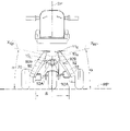
ボディ後部11Rは、後部の左右の側面15Rの対応する配向に起因して、その平面図(図1G)及び背面図(図1F)で見られるように、集束する構成を有する。より具体的には、これらの側面15Rは、ボディ後端12R(図1G)から離れる方向に且つ基準面RP(図1F)から離れる方向に互いにより近づいていくように傾斜される。
The body rear 11 R has a converging configuration, as seen in its plan view (FIG. 1G) and rear view (FIG. 1F), due to the corresponding orientation of the left and
図1Hを参照すると、ボディ部材10の後部側面15Rは、それぞれ、対応する後脚70をその上に保持するためにその外側部分18がその自由端19と共に後部側面から突き出るようにボディ後部11R(右の軸だけが見られる)に固定的に設置される連接軸16を備える。連接軸16の各外側部分18は、対応するピボット軸XRPに沿って延び、ピボット軸XRPは、関連する後部側面15Rに垂直に配向され、この後部側面15Rと後部連接点PRA(このような点の1つだけが見られる)で交差する。2つの後部の左右の側面15Rの後部連接点PRAは、それらを接続する想像線が車両の縦軸Lと交差するように存在することができる(図示せず)。
Referring to FIG. 1H, the rear sides 15R of the
後部側面15Rは、これに垂直な後軸XRPが基準面RPと所望の角度をなすように配向される。より具体的には、図1Fで見られるように、後ピボット軸XRPは、それぞれ基準面RPと鋭角αをなす。これにより、それらのピボット軸XRPが基準面RPに平行な平面内に位置する状態で同じ脚が有することになる間隔に対して、それらの動作配向において後脚の遠位端間の増加した間隔Sを得ることができる。加えて、図1Gで見られるように、各ピボット軸XRPは、車両の対称面SPに関して鋭角βに配向される。これにより、後脚の後ピボット軸XRPを中心とした動作配向から収納配向へのピボットが、結果的に、上記の増加した間隔にもかかわらず、対称面からそれらの近位端と同じ又はほぼ同じ程度に離間されるように、それらの遠位端を対称面に確実により近くする。さらに、実際には、上記の角度βに起因して、脚の収納配向にあるときの後脚の遠位端は、それらの近位端よりも互いにより一層近くすることができ、これにより、図3A及び図3Bを参照してより詳細に後述するように、対称面に垂直な方向の車両の「収納状態」でのコンパクトさを向上させる。
The
図1B、図1G、及び図1Hを参照すると、後脚70のそれぞれは、近位端74、後輪WRを支える遠位端76、及び接続機構90(図1Aでより良く見られる)に関連した脚近位端と脚遠位端との間の接続領域78(図1B及び図1Hでは1つだけ見られる)を備える、細長い本体72を有する。各後脚70は、ボディ部材から離れる方に面する後脚外面75と、ボディ部材の方向に面し、接続領域78を備える後脚内面77とをさらに備える。
1B, 1G, and 1H, each of the
後脚70のそれぞれには、その近位端に隣接して貫通チャネル79が形成され、貫通チャネル79は、後脚の内側側面77と外側側面75との間に延び、脚が連接軸から外れることを防止しながら脚の連接軸を中心としたピボットを可能にするべく、脚の内側側面から連接軸16の外側部分18を受け入れ、且つ外側側面から連接軸16の自由端19と固定的に係合するように構成されたストッパ(図示せず)を受け入れるように構成される。
Each of the
脚の近位端にある各後脚内面77は、車両の収納状態と動作状態との両方においてこれらの表面が互いに密接に接触することができるように、ボディ部材10の対応する後部側面15Rと同様に配向され、これと同延である。
Each rear leg
車両の動作状態において、脚70は、後輪WRが平面RPに沿って前輪WFから最大距離に配置される動作配向を有する。後輪WRは、後脚70の動作配向において互いに共線の車輪軸XWRを有し、2つの後輪WRが車両1の動作状態において互いに平行に機能的に一緒に走行することを可能にする。
In the operating state of the vehicle, the
図1Dを参照すると、フロント組立体50は、対称面SP内に位置するフロントバー軸XFBに沿って延び、前輪WFに関連したホイール端52A及びハンドルバー57に関連したハンドルバー端52Bを有する、フロントバー52を備える。フロントバー52は、そのハンドルバー57と共に、車両1を操縦するためにフロントバー軸XFBを中心として旋回するように構成することができる。フロントバー52の動作配向において、そのハンドルバー端52Bは、基準面RPから最大距離に配置される。
Referring to FIG. 1D, the
図1Eを参照すると、ハンドルバー57は、それらの動作配向において、それらの端がフロントバー52及び対称面SPから最大限に離間され、且つそれらがハンドルバー軸XHBを中心としてそれぞれ回転可能であるように、車両の対称面SPに対して概して横方向に延びるハンドル部58を有し、ハンドルバー軸XHBは、ハンドル部58の収納配向において、それらの端を対称面SPから最小限に離間することができるように、平面SPに概して平行に延びる。
Referring to FIG. 1E, the
フロントバー52のホイール端52Aに、前輪WFを回転可能に保持するフォーク54が形成される。フォーク54の開口部を通して前輪に設置された対応するペダル軸53によってペダルPがそれぞれ保持され、フォークの開口部をペダル軸は自由に通る。各ペダルは、その軸53に対して横方向に配向される動作配向と、この軸と整列される収納配向との間で旋回するように構成することができる。ペダルは、それらの軸と共に、前輪から取り外し可能とすることができる。
A wheel end 52A of the
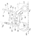
図1Cを参照すると、フロント組立体50は、前ピボット軸XFPを中心としてフロントバー52をボディ部材10の前端12Fにピボット連接するための連接部材60をさらに備え、前ピボット軸XFPは、対称面SPに垂直(且つ基準面RPに平行)であり、且つ前連接点PFでボディ部材10の前部の各側部15と出会う。前ピボット軸XFPは車両の縦軸Lと交差する。
Referring to FIG. 1C, the
連接部材60は、前ピボット軸XFPを中心としてボディ部材の前部にピボット運動可能に接続されるボディ部材関連部分62と、フロントバーの2つの端間に位置する区域に沿ってフロントバー52に接続されるフロントバー関連部分64と、接続機構90の一部をなす後脚関連部分66とを備える。フロントバー関連部分64及び後脚関連部分66は、連接部材60の動作配向において、フロントバー関連部分64がボディ部材関連部分62の前方に配置され、且つ後脚関連部分66がボディ部材関連部分62よりも基準面RPにより近く配置されるように形成される。フロントバー52がフロントバー軸XFBを中心として旋回するように構成される説明される例では、フロントバー関連部分64は、スリーブの形態であり、フロントバー52をスリーブ内で旋回可能な様態で受け入れる。
Linking
連接部材60は、ボタン61を含む係止部を備えることができ、これは、少なくとも車両の動作状態において連接部材60がボディ部材10に係止され、車両の状態を変化させることが望まれるときにだけボタン61を押すことでボディ部材10から係止解除され、前ピボット軸XFPを中心として連接部材60がピボットすることを保証する。
The
図1A、図1F、及び図1Hを参照すると、連接部材60は、2つの縦方向の接続要素又はバー92によりフロントバー52を脚70の接続領域78と接続し、各接続要素92は、接続要素92の前接続軸XFCを中心とした後脚関連部分66に関するピボットを可能にするべく連接部材60の後脚関連部分66の一方の側部に取り付けられる前接続端92Aと、接続要素92の後接続軸XRCを中心とした後脚70に関するピボットを可能にするべく脚70の一方の接続領域78に取り付けられる後接続端92Bとを有する。接続要素92は、それらの動作中にそれらの寸法が変化なく維持されるように剛性の材料で作製される。
1A, 1F and 1H, the connecting
ここで、車両1を図1A~図1F並びに図2Aに示されたその動作状態から図2E、図3A、及び図3Cに示されたその収納状態にするために車両1を折り畳むプロセスを例示する、図2A~図2Eへの参照を行う。車両は、図1A~図1F及び図2Aでは、平面、すなわち基準面RP(図1Fに示される)に沿った乗ることができるその動作状態で示され、図2E、図3A、及び図3Bでは、その縦軸が該平面と動作状態においてそれらの間に形成される角度を超えない角度をなすようにこのような平面上に自由に置くことができるその収納状態で示される。このプロセスは、車両1をそれらの動作配向からそれらの収納配向にするときに車両1の要素がそれを中心としてピボット/旋回されることになる軸に関連して以下で説明され、図2Aを参照すると、これらの軸は以下の通りである:
- ハンドルバー軸XHB:これを中心として、ハンドルバー57が、ハンドルバーのハンドル部58がフロントバー52及び対称面SPからそれらの最大距離に配置される図2Aに示されたそれらの動作配向から、ハンドルバーのハンドル部58がフロントバー52及び対称面SPからそれらの最小距離に配置される図2Bに示されたそれらの収納配向へ回転される;
- 背もたれ軸XBR:これを中心として、
(a)安全フレーム36が、基準面RPと最小角度をなす図2Aに示されたその動作配向及び同じ構成をとる図2Eに示されたその収納配向と、基準面RPと最大角度をなす図2Bに示されたその直立配向との間で回転され、
(b)背もたれ部37が、基準面と最大角度をなす図2Aに示されたその概して垂直な動作配向から、基準面と最小角度をなす図2Eに示されたその概して水平な収納配向へ回転される;
- 前ピボット軸XFP:これを中心として、フロントバー52が連接部材60によって、縦軸L及び基準面RPと最大角度をなす図2Aに示されたその動作配向と、縦軸L及び基準面RPと最小角度をなす図2Dに示されたその収納配向との間で時計回り(CW)にピボットされる;図2Cは、フロントバー52が収納配向に達する前に上記のピボット運動中にとる中間配向を示す;
- 後ピボット軸XRP(このような軸のうちの1つだけが見られる):これを中心として、後脚70が、対応する接続要素92を介して連接部材60によって引っぱられるときに、後輪が前輪WFから最大限に離間される図2Aに示された後脚の動作配向から、後輪WRが前輪WFから最小限に離間される図2Eに示された脚の収納配向へピボットされる;フロントバー52と後脚70が接続機構90によって互いに接続されるので、フロントバーの前ピボット軸XFPを中心としたCW旋回が、後脚の各軸XRPを中心とした同様のCW旋回をもたらす;
- 前接続軸XFC:これを中心として、各接続要素92が連接部材60に対してピボットされる;
- 後接続軸XRC(図2A~図2Eでは見られない):これを中心として、前述のようにフロントバー及び後脚がピボットされるときに、各接続要素92が後脚70に対してピボットされる。
We will now illustrate the process of folding the
- handlebar axis X HB : around which the
- the backrest axis X BR : around which
(a) View of
(b) the
- the front pivot axis X FP : about which the
- a rear pivot axis X RP (only one such axis is visible): around which the
- the front connecting axis X FC : about which each connecting
- the rear connection axis X RC (not visible in Figures 2A-2E): around which each
したがって、車両1がその動作状態からその収納状態へ折り畳まれるときに、図2Bに示すように、最初にそのハンドルバーがそれらの収納配向にされ、安全フレームがその直立配向にされ、次いで、図2C及び図2Dに示すように、フロントバー及び後脚がそれらの収納配向へピボットされ、次いで、図2Eに示すように、背もたれがその収納配向へピボットされ、同時に又はその後、安全フレームがその水平配向へピボットされる。加えて、ペダルPが、車両の折り畳まれた状態でのスペースを節約するべく折り畳まれる。車両は、上記のステップを逆の順序で行うことによってその動作状態に戻すことができる。
Thus, when the
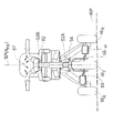
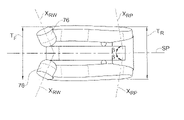
図3Bを参照すると、後ピボット軸XRP間の角度2βにより、これらの軸を中心として脚70を旋回させたときに、それらの遠位端76がそれらの近位端よりも対称面SPにより近くなり、ボディ部材の前端の領域でのその横方向の長さTFがボディ部材の後端の領域でのその横方向の長さTRを超えることができない又は少なくとも本質的に超えることができないように車両1の収納状態におけるコンパクトな構成が可能となる(図3A)。車両1の収納状態において、後輪軸XWRは、図3Aで明瞭に見られるように互いに或る角度をなすことになることも分かる。
Referring to FIG. 3B, the angle 2β between the posterior pivot axes X RP causes their distal ends 76 to be closer to the plane of symmetry SP than their proximal ends when the
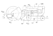
図3A及び図3Eを参照すると、各後脚がボディ部材の後部の対応する側部に個々に連接されることにより、脚の動作配向から収納配向へのピボット角度は、その収納配向において各後脚がボディ部材の前端の近くにその遠位端を有し、この端から前方に本質的に突き出ないようにするだけ大きい。その結果、図3Cで見られるように、その側面図で見られる車両の収納状態において、各後脚及び関連する後輪は、ボディ部材の後端と前輪との間に主に収まり、これにより、この状態での基準面に沿った車両の長さを減少させることが可能となる。 With reference to Figures 3A and 3E, each rear leg is individually articulated to a corresponding side of the rear of the body member so that the leg's pivot angle from the operative orientation to the stowed orientation is equal to that of each rear leg in its stowed orientation. The leg has its distal end near the front end of the body member and is large enough not to project essentially forward from this end. As a result, as seen in FIG. 3C, in the stowed condition of the vehicle as seen in its side view, each rear leg and associated rear wheel rests primarily between the rear end of the body member and the front wheel, thereby , it is possible to reduce the length of the vehicle along the reference plane in this state.
さらに、図3Eを参照すると、各後脚70は、ボディ部材10の形状及び幅に対して、車両の収納状態において、それらが車両の側面図において前述のようにそれらの長さの大部分に沿ってだけでなくそれらの高さの大部分に沿っても重なることができるような形状及び幅を有し、脚70が車両の収納状態においてボディ部材から下方に突き出ないようにする。
Further, referring to FIG. 3E, each
図3Dを参照すると、フロントバー軸XFBは前ピボット軸XFPと一致しない、すなわち、バー52は連接部材60により前ピボット軸XFPに関してオフセットOSされているので、バー52によって行われる回転運動は、車両の収納状態において、その軸XFBが縦軸Lと極めて小さい角度γをなすように、且つそのハンドルバー端52Bが、基準面RPから、基準面RPと前輪WFの最高点との間の距離を少なくとも超えない距離に離間されるだけ低く配置されている状態で座席32よりも上に存在するように、バー52を配置することを可能にすることに注目される。この例では、上記の設計は、折り畳み可能な背もたれ部37を上方からハンドルバー端52B上に閉じることを可能にする。
Referring to FIG. 3D, since the front bar axis X FB does not coincide with the front pivot axis X FP , i.e., the
さらに、図3Dで見られるように、車両の収納状態において、前輪WF及び後輪WR(左の後輪だけが示されている)は、ボディ部材10の底面14から下方に突き出ない。
Further, as seen in FIG. 3D, in the stowed condition of the vehicle, the front wheels W F and rear wheels W R (only the left rear wheel is shown) do not project downwardly from the
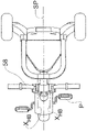
ここで図4A及び図4Bに移ると、子供が一人で乗ることができる車両と、そのフロントバー52全体を車両の後方から別の人、例えば大人が操縦可能な乳母車と、の両方として用いられるように構成される、概して100で表される車両が示される。前述した車両1の構成要素と同じ車両100の構成要素は同じ参照番号で表される。加えて、車両100は、リア操縦ハンドル80と、ハンドル80の回転運動をフロントバー52の回転運動に変換するためのリア操縦機構を有する。
Turning now to Figures 4A and 4B, it can be used both as a vehicle that a child can ride alone and as a pram that can be steered from the rear of the vehicle by another person, e.g. an adult, with its
特に、操縦機構は、フロントバー52に固定的に取り付けられ、それと共に旋回するように構成された、フロント回転部材86(図4Bに点線で概略的に示される)と、ボディ部材後部内に配置され、操縦ハンドル80によって旋回されるように構成された、リアポート87と、同じく図4Bに点線で概略的に示されるようにボディ部材10内でフロント部材とリアポートとの間に延び、右及び左の側部において、それぞれ、それらの一方の端がフロント部材86にその直径方向反対側2個所で固定的に取り付けられ且つそれらの他方の端がリアポート87にその直径方向反対側それぞれで固定的に取り付けられる、一対の右及び左操縦ケーブル区域84と、を備える。
In particular, the steering mechanism is located within a front rotating member 86 (schematically shown in dashed lines in FIG. 4B) fixedly attached to the
この構成は、ケーブル区域84をフロント部材86及びリアポート87に固定的に取り付けているので、ケーブル区域84のうちの1つを引っぱると、フロント部分86がフロントバー52の縦軸XFBを中心として旋回し、これにより、フロントバー52が旋回して車両の操縦が可能となるような構成である。
This configuration fixedly attaches the
ケーブル区域は、車両100がその動作状態からその収納状態へ折り畳まれるときにそれらが前ピボット軸XFPの付近で屈曲することを可能にする、自転車ブレーキケーブルに用いられるのと同じ種類のものとすることができる、屈曲可能な材料で作製される。
The cable sections are of the same type used in bicycle brake cables, allowing them to flex about the front pivot axis XFP when the
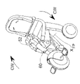
図5Aは、子供が単独で乗るように構成された車両として、又は別の人によって操作されるリア操縦ハンドル(図示せず)により操縦されることになる乳母車としても用いることができる車両200を例示する。車両200は、前述した車両1及び100の構成要素と概して同じ構成要素を有し、その違いは、車両200のこれらの構成要素の一部に関して、それらを実装することができる1つの特定の様態に関するさらなる詳細が図5Bで提供されることである。しかしながら、これらの構成要素は、概して他の様態で実装することができることを理解されたい。さらに、図5Bは、これらの構成要素のすべての詳細を提示するものではなく、200をつけた車両1及び100の説明で用いられた参照番号に対応する参照番号によって以下に記載され表されるものだけを提示するものと考えられるべきである。図5Bは、標準の又は自明の構造要素は示さないことにも留意されたい。分解された状態でこの図に示されるほとんどの要素は、車両200の右側(図5A及び図5Bで最もよく見られる)に関係しており、これは車両200の左側の鏡像であり、ゆえに、他に特に示されない限り、車両の右側に関して示されたのと同じ要素がその左側にも存在することも理解されたい。
FIG. 5A illustrates a
したがって、車両200は、右及び左ハウジング部品210を有する中空のハウジングを備え、右及び左ハウジング部品210は、それぞれ、前部外面215F及び後部外面215R(右ハウジング部品210のものだけが見られる)と、前部内面215F’及び後部内面215R’(図5Bでは左ハウジング部品210のものだけが見られる)を備える。ハウジング部品210は、図5Aに示すようにそれらのリムに沿って組み立てられるときにボディ部材210を構成し、この場合、2つのハウジング部品の前部側面215Fがそれらの間にボディ部材の前部211Fを画定し、2つのハウジング部品の後部側面215Rがそれらの間にボディ部材の後部211Rを画定する。この例では、ボディの前部と後部は、ボディ部材の中間部211Intによって互いから離間され、ボディ部材の中間部211Intの外面及び内面(図に符号なし)は、それぞれ、前部側面215Fと後部側面215Rとの間及び前部内面215F’と後部内面215R’との間に配置される。
Thus, the
図5Bで見られる右ハウジング部品210及び左後脚270を参照すると、2つのハウジング部品の後部外面215Rは、それぞれ、この表面が車両1の後部表面15Rに関連して前述したのと同様に配向されるように形成された、ボディ部材の後部211Rの一部をなす突出部217に属する。各突出部217は、その後部外面215Rに対して垂直に配向された外側部分218を有し、且つ自由端219を有する、連接軸216を固定的に保持する。
With reference to the
図5Bの右脚及び左脚270を参照すると、これらはそれぞれ、後脚外面275及び後脚内面277と、それらの間に延びる貫通チャネル279とを有し、貫通チャネル279は、脚の内側側面277から連接軸216の外側部分218を、及び脚の外側側面275からストッパ310を受け入れるように構成され、ストッパ310は、そこでチャネル279が終端するポケット312内に受け入れられ、脚が連接軸から外れることを防止しながら脚の連接軸を中心としたピボットを可能にするべく連接軸216の自由端219と固定的に係合するように構成される。
Referring to right and left
図5Bの左後脚270をさらに参照すると、各後脚は、その内側側面277に接続領域278を備え、接続領域278は、この例では、内側側面277から突き出るピンの形態であり、それに2つの縦方向の接続バー292のうちの1つとその後接続端292Bで接続して、接続バー292の後脚270に関するピボットを可能にするように構成される。各接続バー292は、フロント組立体250の一部をなす連接部材260に取り付けられる前接続端292Aをさらに有する。
With further reference to the left
図5Bに示すように、連接部材260は、
- 接続機構290(図に符号なし)の一部をなす、2つの接続バー292がそれらの前接続端292Aでピボット運動可能に接続される2つの側部を有する、後脚関連部分266と、
- ボディ前部211F(図5Aで見られる)にピボット運動可能に接続される、ボディ部材関連部分262と、
- フロントバー252の上部252Bが連接部材に直接接続されないようにフロントバー252の下部252Aを回転可能に受け入れる、フロントバー関連部分264と、
を備える。
As shown in FIG. 5B, connecting
- a rear leg-related
- a body member associated
- a front bar associated
Prepare.
フロントバー252の上部252A及び下部252Bは、係止体320(図5Aと図5Bとの両方で見られる)によって互いに係止されたときに互いに固定的に接続されて単一の一体のフロントバーユニットを構成し、互いから係止解除されたときに機能的に接続解除されることにより詳細に後述するリア操縦機構によって下部を操縦することが可能となり且つ上部が固定的な配向を有するか又は下部から独立して回転可能となるように、互いに組み立てられる。
Upper and
図5Bにさらに示されるように、車両200は、その動作配向において連接部材260を係止するための右係止機構及び左係止機構を備え、両方の係止機構は、前ピボット軸XFPに沿って動作し、それぞれ、
- その円周に沿った突起のパターンを有する、ばね付き係止要素265(ばねは267で別に表される)と、
- 対応するハウジング部品210(図5Bでは左ハウジング部品で見られる)の前部内面215F’に形成され、その動作配向においてばね付き係止要素265を内部に嵌め込むことができるように係止要素の突起のパターンに対応する凹部の周方向パターンを有する、係止キャビティ268と、
- 連接部材260のボディ部材関連部分262の対応するハウジング部品に面する側部に形成され、係止要素265の突起のパターンに対応する凹部の周方向パターンを有する、連接キャビティ271であって、ばね267及び係止要素265を恒久的に受け入れ、係止要素に軸方向の押し込み力が及ぼされる、したがってばねが押されるときに、係止要素が連接キャビティへより深く入ることを可能にするように構成された、連接キャビティ271と、
- プロング281を有する、ボタン261と、これに対応する形状に設定され、ハウジング部品210の前部内面215F’と前部外面215Fとの間に延びるように形成され、車両200の動作状態及び収納状態においてボタンがその最も外側の位置にあるときと、ボタンがそのプロング281によってばね付き係止要素265上に軸方向に押す力を及ぼすためにその最も内側の位置へ押されるときとの両方においてボタンのプロング281を受け入れるように構成された、貫通通路283と、
- 連接部材260のボディ部材関連部分262及びフロントバー関連部分264を覆い、必要なときにボタンを押すためにユーザがボタンにアクセスできるようにボタン261を収容するための開口部285を有する、カバー299と、
を備える。
As further shown in FIG. 5B, the
- a spring-loaded locking element 265 (the spring is separately represented at 267) having a pattern of protrusions along its circumference;
- formed on the front inner surface 215 F ' of the corresponding housing part 210 (seen on the left housing part in Fig. 5B), locking such that in its operational orientation the spring-loaded
-
a
- A cover that covers the body member associated
Prepare.
したがって、車両200の動作状態において、ばね付き係止要素265は、それらの係止位置にあり、それぞれ係止キャビティ268内に収容されており、連接キャビティ271内へ最小限に突き出る。車両200の状態を動作状態から収納状態に変化させるときに、右及び左の係止機構が連接部材260を係止解除するべく同時に操作され、これにより、連接部材260が車両1に関連して前述したように前ピボット軸XFPを中心としてその動作配向からその収納配向にピボットすることが可能となる。
Thus, in the operating state of the
係止解除は、右及び左のボタン261を押すことによって開始され、これにより、プロング282が係止要素265上に軸方向に押す力を及ぼして、係止要素265を係止キャビティ268から連接キャビティ271へ最大限に移動させる。この係止解除位置において、係止要素265は、もはや連接部材260がボディ部材210に関してピボットすることを防ぐことができず、係止要素265は、連接部材260と一緒にピボットし、連接部材260が係止要素265と共にその動作配向に戻るようにピボットされて係止要素が係止キャビティ268と位置合わせされるまで、そのように係合されたままである。この位置合わせが達成されるときに、各係止要素265が、その対応するばね267によって係止キャビティ268内のその係止位置に押し戻される。
Unlocking is initiated by pressing the right and left
車両200は、図4A及び図4Bに示された車両100に関して説明したようにハンドル80(図5A及び図5Bには図示せず)と共に用いるための、ハンドルのピボット運動をフロントバー252のピボット運動に変換する、リア操縦機構をさらに備える。操縦機構は、
- 連接部材260のフロントバー関連部分264の内部に配置され、フロントバー252に固定的に取り付けられ、フロントバー252と共に旋回するように構成された、フロント回転部材286と、
- 一対の右及び左操縦ケーブル区域284を有し、ケーブル区域284のうちの1つを引っぱるとフロント回転部材286がフロントバー252と共に旋回することにより車両の操縦が可能となるように、ケーブル区域284の一方の端がそれに固定的に取り付けられ、ケーブル区域284の他方の端がフロント回転部材286に固定的に取り付けられる、リアポート287と、
- その内部がケーブル通路(図に符号なし)と合流し、ケーブル区域284がケーブル通路、ボディ部材210の内部、及びフロントピース286を通っている状態でリアポート287をハンドル80によって回転されることが可能な様態で受け入れるべくボディ部材の後部211R内に固定される、リアポートカップ289(ハウジング左部分と組み立てられた状態で示される)と、
を備える。
- a
- having a pair of right and left
- the
Prepare.
連接部材260をフロントバー252及びフロント部材286と一緒にピボットさせることによって車両が動作状態から収納状態へ折り畳まれるときに右及び左ケーブル区域284が望みどおりに確実に屈曲されるようにするために、ケーブル区域は、それぞれ右又は左のボタン261のプロング281の間を通り、プロングをケーブル区域が屈曲されるべきケーブル区域の位置に固定することができるように、ボディ部材210内に延びる。
To ensure that the right and left
車両200は、フロントバー252の上部252Bを安全フレーム236に係止するためにその安全フレーム236に取り付けられたフロントバー係止クランプ300をさらに備え、これは、その動作配向にあるときに(図5Bで見られるように)、フロントバーの下部が操縦されるときにこの部分が固定の配向を有するようにする。
最後に、車両のペダルPは、前述のように及び図5Aに示されるように両方とも前輪WFに設置可能であり、収容された子供が動かすことと、連接部材260が図5Cに示すようにその後脚関連部分266で前輪WFよりも座席部30により近く配置されたフットレストを構成し、したがって車両200の乳母車としての使用を容易にすることを可能にする。座席部30は、少なくとも2つの位置に設置するように構成することができ、その位置のうちの1つは図5A及び図5Cに示され、もう1つ(図示せず)はフロントバー252により近い。
Finally, the vehicle pedals P can be mounted on the front wheels WF, both as previously described and as shown in FIG. In addition, the rear leg-related
Claims (4)
- ボディ部材であって、前記ボディ部材は、座席を保持する上面と、前記縦軸に沿って互いから離間された前端及び後端と、両方とも前記ボディ部材の後端に隣接して配置され、前記垂直対称面に垂直な方向に互いから離間された後部右側面及び後部左側面とを有する、ボディ部材と、
- その動作配向と収納配向との間でピボットされるように、前ピボット軸を介して前記ボディ部材の前部に少なくとも間接的にピボット式に連接され、前記車両の前輪を保持するフロントバーと、
- それぞれ、動作配向及び収納配向をとるべく後ピボット軸を介して前記ボディ部材の後部にピボット式に連接され、前記車両の後輪を保持する2つの後脚と、
- 前記車両がその動作状態にあるときに、リア操縦ハンドルを用いるために前記リア操縦ハンドルをその中に固定して受け入れるように構成された回転可能なリア操縦ポートと、
- 前記車両を操縦するために、その動作状態にあるときに、前記リア操縦ハンドルによる前記回転可能なリア操縦ポートの回転が少なくとも前記フロントバーの下部を回転させるように前記回転可能なリア操縦ポートを前記フロントバーと接続する操縦機構であって、前記操縦機構は、前記ボディ部材内に少なくとも部分的に延び、前記フロントバーがその動作配向からその収納配向にピボットされるときに、前記前ピボット軸の近傍で屈曲されるように構成された少なくとも1つの操縦要素を備える、操縦機構と、
を備える、車両。 A foldable personal vehicle having an operational state and a stowed state, said vehicle having a longitudinal axis lying in a vertical plane of symmetry of said vehicle, said vehicle comprising:
- a body member having a seat-retaining upper surface and front and rear ends spaced apart from each other along said longitudinal axis, both positioned adjacent the rear end of said body member; a body member having a rear right side and a rear left side spaced apart from each other in a direction perpendicular to said vertical plane of symmetry;
- a front bar pivotally connected at least indirectly to the front portion of said body member via a front pivot axis so as to be pivoted between its operative and stowed orientations and holding the front wheels of said vehicle; ,
- two rear legs pivotally connected to the rear portion of said body member via a rear pivot axis for carrying the rear wheels of said vehicle in working and stowed orientations, respectively;
- a rotatable rear steering port configured to fixedly receive the rear steering handle therein for use with the vehicle when the vehicle is in its operational state;
- said rotatable rear steering port such that, when in its operational state, rotation of said rotatable rear steering port by said rear steering handle rotates at least the lower portion of said front bar to steer said vehicle; with the front bar, the steering mechanism extending at least partially into the body member and when the front bar is pivoted from its operating orientation to its stowed orientation, the front pivot a steering mechanism comprising at least one steering element configured to bend about an axis;
a vehicle.
Applications Claiming Priority (3)
| Application Number | Priority Date | Filing Date | Title |
|---|---|---|---|
| IL249515A IL249515B (en) | 2016-12-12 | 2016-12-12 | Foldable personal vehicle |
| IL249515 | 2016-12-12 | ||
| JP2017235725A JP7085825B2 (en) | 2016-12-12 | 2017-12-08 | Foldable personal vehicle |
Related Parent Applications (1)
| Application Number | Title | Priority Date | Filing Date |
|---|---|---|---|
| JP2017235725A Division JP7085825B2 (en) | 2016-12-12 | 2017-12-08 | Foldable personal vehicle |
Publications (2)
| Publication Number | Publication Date |
|---|---|
| JP2022111237A true JP2022111237A (en) | 2022-07-29 |
| JP7284855B2 JP7284855B2 (en) | 2023-05-31 |
Family
ID=60673176
Family Applications (2)
| Application Number | Title | Priority Date | Filing Date |
|---|---|---|---|
| JP2017235725A Active JP7085825B2 (en) | 2016-12-12 | 2017-12-08 | Foldable personal vehicle |
| JP2022092413A Active JP7284855B2 (en) | 2016-12-12 | 2022-06-07 | foldable personal vehicle |
Family Applications Before (1)
| Application Number | Title | Priority Date | Filing Date |
|---|---|---|---|
| JP2017235725A Active JP7085825B2 (en) | 2016-12-12 | 2017-12-08 | Foldable personal vehicle |
Country Status (13)
| Country | Link |
|---|---|
| US (5) | US10933938B2 (en) |
| EP (2) | EP3663179B1 (en) |
| JP (2) | JP7085825B2 (en) |
| CN (3) | CN111332398B (en) |
| AU (3) | AU2017276154B2 (en) |
| CA (3) | CA2988284A1 (en) |
| ES (1) | ES2909374T3 (en) |
| HR (1) | HRP20220316T1 (en) |
| IL (1) | IL249515B (en) |
| PL (2) | PL3663179T3 (en) |
| RU (1) | RU2750757C2 (en) |
| SG (2) | SG10201710288WA (en) |
| ZA (1) | ZA201708372B (en) |
Families Citing this family (18)
| Publication number | Priority date | Publication date | Assignee | Title |
|---|---|---|---|---|
| IL249515B (en) * | 2016-12-12 | 2019-08-29 | Doona Holdings Ltd | Foldable personal vehicle |
| US20180257727A1 (en) * | 2017-03-13 | 2018-09-13 | Jin Ye | Foldable three-wheeled scooter |
| JP6952651B2 (en) * | 2018-06-11 | 2021-10-20 | 怡合国際企業有限公司 | Tricycle for infants |
| US10562583B1 (en) * | 2018-09-11 | 2020-02-18 | Puc Perfect Union Co., Ltd. | Folding electrically powered vehicle |
| CN109383678B (en) * | 2018-10-15 | 2025-10-24 | 好孩子儿童用品有限公司 | Folding stroller |
| CN109969246A (en) * | 2019-04-11 | 2019-07-05 | 上海电机学院 | A multifunctional deformable electric stroller |
| CN111824308B (en) * | 2019-04-15 | 2025-02-07 | 嘉兴小虎子车业有限公司 | Foldable baby stroller |
| GB201905308D0 (en) * | 2019-04-15 | 2019-05-29 | All Day Designs Ltd | Transportation apparatus |
| WO2020210927A1 (en) * | 2019-04-15 | 2020-10-22 | 嘉兴小虎子车业有限公司 | Foldable stroller |
| US11370504B2 (en) | 2020-09-03 | 2022-06-28 | Barbara Evans | Mobility scooter with folding feature and related methods |
| FR3123037B1 (en) * | 2021-05-18 | 2024-02-23 | Id Development Ltd | Children's vehicle |
| FR3123036B1 (en) * | 2021-05-18 | 2024-02-02 | Id Development Ltd | Children's vehicle |
| CN113682409A (en) * | 2021-09-15 | 2021-11-23 | 张鸿 | Multifunctional children riding vehicle |
| CN113859349B (en) * | 2021-11-22 | 2024-10-01 | 中山市贝乐斯日用制品有限公司 | Foldable baby stroller framework |
| CN114590351B (en) * | 2022-03-04 | 2024-07-12 | 福建省贝思瑞婴童用品有限公司 | Multifunctional foldable child tricycle and working method thereof |
| US20240253727A1 (en) * | 2023-02-01 | 2024-08-01 | Fujian Besrey Technology Co., Ltd. | Multi-functional foldable children's tricycle and its mode of operation |
| CN117550005A (en) * | 2023-02-21 | 2024-02-13 | 深圳对鹅科技有限公司 | Suspension structures and bicycles |
| US20240343341A1 (en) * | 2023-04-12 | 2024-10-17 | The Radio Flyer Company | Multi-configuration cycle |
Citations (2)
| Publication number | Priority date | Publication date | Assignee | Title |
|---|---|---|---|---|
| US6530589B1 (en) * | 2002-03-22 | 2003-03-11 | New Art City Industrial Co., Ltd. | Structure of a bicycle for children |
| US20080277901A1 (en) * | 2005-09-29 | 2008-11-13 | Artsana S.P.A. | Size-Reducible Folding Tricycle for Children |
Family Cites Families (85)
| Publication number | Priority date | Publication date | Assignee | Title |
|---|---|---|---|---|
| US1106939A (en) * | 1912-09-13 | 1914-08-11 | Frederick Gutmann | Collapsible veclocipede. |
| US2212741A (en) * | 1938-11-09 | 1940-08-27 | Johnson Lorenzo Ralph | Convertible vehicle |
| US2194161A (en) * | 1939-01-14 | 1940-03-19 | Chester L Cobb | Foldable tricycle |
| US3639748A (en) | 1970-11-27 | 1972-02-01 | Goodyear Tire & Rubber | Bumper structure having a light fixture associated therewith |
| IT959727B (en) * | 1972-05-19 | 1973-11-10 | Miranda A | TRICYCLE FOR CHILDREN WITH FOLDABLE ARTICULATED FRAME |
| US3869167A (en) | 1973-10-01 | 1975-03-04 | Ford Motor Co | Resilient bumper assembly |
| SU1244001A1 (en) | 1985-01-02 | 1986-07-15 | Центральное Конструкторско-Технологическое Бюро По Велостроению | Childъs tricycle |
| SU1761579A1 (en) * | 1990-01-03 | 1992-09-15 | Центральное Конструкторско-Технологическое Бюро Велостроения | Pivot of collapsible bicycle frame |
| US4974125A (en) | 1990-02-28 | 1990-11-27 | Mcgehee Michael G | Vehicular light bar arrangement |
| RU2025386C1 (en) | 1992-06-08 | 1994-12-30 | Санкт-Петербургское высшее художественно-промышленное училище им.В.И.Мухиной | Folding bicycle-cart |
| US6152473A (en) * | 1999-07-14 | 2000-11-28 | Shih; Wen Fu | Folding collapsible baby tricycle |
| US6575486B2 (en) * | 2001-11-01 | 2003-06-10 | New Art City Industrial Co., Ltd. | Folding structure of a children tricycle |
| US6609723B2 (en) * | 2001-11-27 | 2003-08-26 | Jin Sun Gee Plastics Co., Ltd. | Collapsible tricycle for the use of young children |
| JP2003175876A (en) | 2001-12-11 | 2003-06-24 | Bridgestone Cycle Co | Foldable tricycle |
| TW535629U (en) * | 2001-12-31 | 2003-06-01 | Tcv Ind Co Ltd | Foot placement frame for toy chart |
| US6612598B2 (en) | 2002-01-25 | 2003-09-02 | Jung-Jyh Wu | Rear steering device for a tricycle for children |
| USD596090S1 (en) | 2002-02-12 | 2009-07-14 | I3Ventures, LLC | Illuminated rub rail |
| JP3088707U (en) | 2002-03-20 | 2002-09-27 | 仙履奇縁針織實業有限公司 | Toddler bicycle |
| JP3090304U (en) | 2002-05-28 | 2002-12-06 | 株式会社野中製作所 | Foldable infant tricycle locking device |
| CN2551558Y (en) | 2002-05-31 | 2003-05-21 | 汕头华美乐童车有限公司 | Child tricycle |
| CN2574978Y (en) * | 2002-08-20 | 2003-09-24 | 马培选 | Electric motorcycle frame |
| KR200298562Y1 (en) * | 2002-09-10 | 2002-12-20 | 철 왕 임 | Fold and unfold three-wheel bicycle |
| US6726233B1 (en) * | 2002-10-07 | 2004-04-27 | Hong Mou Enterprise Co., Ltd | Toddler tricycle folding footboard structure |
| US7000935B2 (en) * | 2003-02-25 | 2006-02-21 | Huffy Corporation | Tricycle and guide handle |
| US6874802B2 (en) | 2003-02-25 | 2005-04-05 | Huffy Corporation | Tricycle and guide handle |
| AU2003902057A0 (en) * | 2003-04-30 | 2003-05-15 | Golias, Matthew | A wheeled vehicle |
| WO2004096619A1 (en) | 2003-08-08 | 2004-11-11 | Freeport Riggings (Pvt) Ltd. | Garment trolley |
| US6966572B2 (en) * | 2003-11-25 | 2005-11-22 | Radio Flyer Inc. | Folding riding vehicle |
| US6840527B1 (en) | 2004-03-15 | 2005-01-11 | Radio Flyer, Inc. | Tricycle with geared auxiliary steering mechanism |
| USD525568S1 (en) | 2004-10-05 | 2006-07-25 | Ofrat Baby Toys Manufacturers Ltd. | Tricycle |
| JP2006298161A (en) * | 2005-04-20 | 2006-11-02 | Nonaka Seisakusho:Kk | Steering device of tricycle for child |
| US7240907B2 (en) * | 2005-08-24 | 2007-07-10 | Far Great Plastics Industrial Co., Ltd. | Tricycle crank structure |
| TWI299028B (en) * | 2006-02-14 | 2008-07-21 | James Chung-Kei Lau | Human powered ground vehicle comprising foldable sections |
| USD555045S1 (en) | 2006-09-18 | 2007-11-13 | Smart Baby Toys / Smart Trike | Tricycle having a canopy, handle and mud guard |
| DE102007037648B4 (en) * | 2007-08-09 | 2010-11-25 | Topeak, Inc. | Folding |
| USD571866S1 (en) | 2007-09-19 | 2008-06-24 | Smart Baby Toys | Deluxe tricycle |
| USD604777S1 (en) | 2008-03-05 | 2009-11-24 | Smart Baby Toys | Tricycle with reclining seat |
| USD594788S1 (en) | 2008-07-07 | 2009-06-23 | Radio Flyer Inc. | Tricycle |
| US8313118B2 (en) | 2009-03-30 | 2012-11-20 | Mattel, Inc. | Children's ride-on vehicle with parent steering assist handle and stationary canopy |
| US8517406B2 (en) * | 2009-06-08 | 2013-08-27 | Huffy Corporation | Position-adjustable vehicle |
| USD627265S1 (en) | 2009-12-15 | 2010-11-16 | Smart Trike MNF. Pte. Ltd. | Tricycle |
| FR2955080B1 (en) * | 2010-01-08 | 2011-12-30 | Smoby Toys S A S | TRICYCLE WITH PARENTAL DIRECTION |
| US8313117B2 (en) | 2010-05-14 | 2012-11-20 | Mga Entertainment, Inc. | Parent steerable tricycle with internal steering limiter |
| ITCT20100015A1 (en) | 2010-10-01 | 2012-04-02 | Blasi Ind Srl Di | FOLDING VEHICLE WITH THREE OR FOUR WHEELS |
| FR2970936B1 (en) | 2011-02-01 | 2013-05-17 | Erick Aveline | TRICYCLE TRANSFORMABLE |
| USD659056S1 (en) | 2011-06-30 | 2012-05-08 | Radio Flyer Inc. | Tricycle |
| US8991844B2 (en) * | 2011-07-01 | 2015-03-31 | Radio Flyer Inc. | Multiple configuration tricycle |
| CN102923228A (en) | 2011-08-12 | 2013-02-13 | 斯马特脚踏车制造公司 | A tricycle and a swivel wheel of the tricycle |
| WO2013036990A2 (en) | 2011-09-12 | 2013-03-21 | Funtastic Limited | An infant's wheeled vehicle |
| ITCT20120002A1 (en) | 2012-02-06 | 2013-08-07 | Blasi Ind Srl Di | FOLDING VEHICLE WITH THREE OR FOUR WHEELS |
| KR101319481B1 (en) * | 2012-04-12 | 2013-10-17 | 김정근 | Bicycle frame and bicycle capable of transforming tricycle using the same |
| CN202703797U (en) * | 2012-06-04 | 2013-01-30 | 泰特乐有限公司 | Tricycle with foldable two wheels |
| US10011316B2 (en) * | 2012-06-04 | 2018-07-03 | Smart Trike Mnf Pte Ltd. | Vehicle with foldable double-wheel assembly |
| ES2643157T3 (en) | 2012-09-03 | 2017-11-21 | Galileo Trikes Ltd. | Multi-stage free wheel and free steering folding tricycle with a single movement release mechanism |
| HK1211908A1 (en) * | 2012-10-16 | 2016-06-03 | 瑞迪菲勒公司 | Foldable tricycle |
| JP5964203B2 (en) | 2012-10-29 | 2016-08-03 | アイデス株式会社 | Folding tricycle |
| US9114842B2 (en) | 2013-02-01 | 2015-08-25 | Radio Flyer Inc. | Multi-passenger tricycle |
| KR101478190B1 (en) * | 2013-03-21 | 2014-12-31 | 온순건 | Baby carriage using bike |
| US8882124B2 (en) * | 2013-03-28 | 2014-11-11 | Fook Fah Yap | Foldable bicycle |
| CN203511916U (en) * | 2013-04-01 | 2014-04-02 | 王建民 | Portable and foldable draw-bar box type electric tricycle with function of folding chair |
| CN103192862A (en) | 2013-04-09 | 2013-07-10 | 高春培 | Foldable multifunctional children's tricycle |
| USD735090S1 (en) | 2013-05-30 | 2015-07-28 | Smart Trike Mnf Pte Ltd | Tricycle |
| CN203450279U (en) * | 2013-07-15 | 2014-02-26 | 天津市金地宝来金属制品有限公司 | Frog type scooter |
| KR20160057414A (en) * | 2013-09-10 | 2016-05-23 | 어번626, 엘엘씨 | Foldable electric vehicle |
| IL228492A (en) * | 2013-09-17 | 2016-11-30 | Doona Holdings Ltd | Baby safety car seat convertible into a rollable baby seat |
| CN103754304A (en) | 2013-11-22 | 2014-04-30 | 重庆盾铭电磁阀有限公司 | Folding tricycle |
| CN203638020U (en) | 2013-11-29 | 2014-06-11 | 好孩子儿童用品有限公司 | Foldable child's tricycle |
| JP6206189B2 (en) | 2014-01-06 | 2017-10-04 | トヨタ自動車株式会社 | Small mobile |
| NL2012245C2 (en) * | 2014-02-12 | 2015-08-17 | Royalty Bugaboo Gmbh | A foldable vehicle. |
| US9039025B1 (en) * | 2014-05-21 | 2015-05-26 | Ming-He Shih | Foldable children's tricycle |
| CN105270530A (en) * | 2014-07-17 | 2016-01-27 | 朱开一 | Foldable baby carriage |
| CA2983606A1 (en) * | 2014-10-07 | 2016-04-14 | Yvolve Sports Ltd. | Vehicle that is convertible to multiple configurations |
| JP6510240B2 (en) | 2015-01-13 | 2019-05-08 | 豊田鉄工株式会社 | Folding vehicle |
| USD777607S1 (en) | 2015-03-06 | 2017-01-31 | Radio Flyer Inc. | Folding tricycle |
| US9873476B2 (en) * | 2015-05-29 | 2018-01-23 | Urban626, Llc | Foldable electric vehicle |
| US10336394B2 (en) * | 2015-06-02 | 2019-07-02 | Radio Flyer Inc. | Foldable tricycle |
| CN204895718U (en) * | 2015-08-06 | 2015-12-23 | 汕头华美乐童车有限公司 | But folding chassis of bassinet |
| CN205022789U (en) | 2015-09-30 | 2016-02-10 | 星辉互动娱乐股份有限公司 | Child's tricycle convenient to it is folding |
| CN105501355B (en) * | 2015-12-21 | 2018-08-28 | 东莞市智乐堡儿童玩具有限公司 | Foldable baby carriage |
| CN205469517U (en) * | 2015-12-21 | 2016-08-17 | 东莞市智乐堡儿童玩具有限公司 | A foldable baby car |
| CN205440711U (en) | 2016-01-05 | 2016-08-10 | 好孩子儭童用品有限公司 | Folding tricycle |
| USD787378S1 (en) | 2016-02-09 | 2017-05-23 | Radio Flyer Inc. | Stroller tricycle |
| CN205615647U (en) * | 2016-05-12 | 2016-10-05 | 鲁立晓 | Multi -functional folding tricycle of children |
| FR3058123B1 (en) * | 2016-10-27 | 2018-11-23 | Swincar | TROTTINETTE WITH THREE WHEELS |
| IL249515B (en) * | 2016-12-12 | 2019-08-29 | Doona Holdings Ltd | Foldable personal vehicle |
-
2016
- 2016-12-12 IL IL249515A patent/IL249515B/en active IP Right Grant
-
2017
- 2017-12-08 CA CA2988284A patent/CA2988284A1/en active Pending
- 2017-12-08 CA CA3297442A patent/CA3297442A1/en active Pending
- 2017-12-08 US US15/836,443 patent/US10933938B2/en active Active
- 2017-12-08 CA CA3297451A patent/CA3297451A1/en active Pending
- 2017-12-08 JP JP2017235725A patent/JP7085825B2/en active Active
- 2017-12-08 RU RU2017143011A patent/RU2750757C2/en active
- 2017-12-11 ZA ZA2017/08372A patent/ZA201708372B/en unknown
- 2017-12-11 AU AU2017276154A patent/AU2017276154B2/en active Active
- 2017-12-11 SG SG10201710288WA patent/SG10201710288WA/en unknown
- 2017-12-11 SG SG10202102375TA patent/SG10202102375TA/en unknown
- 2017-12-12 CN CN202010128149.3A patent/CN111332398B/en active Active
- 2017-12-12 HR HRP20220316TT patent/HRP20220316T1/en unknown
- 2017-12-12 ES ES20153460T patent/ES2909374T3/en active Active
- 2017-12-12 CN CN201711322044.6A patent/CN108216460B/en active Active
- 2017-12-12 EP EP20153460.9A patent/EP3663179B1/en active Active
- 2017-12-12 CN CN202010127952.5A patent/CN111332397B/en active Active
- 2017-12-12 EP EP17206705.0A patent/EP3333057B1/en active Active
- 2017-12-12 PL PL20153460T patent/PL3663179T3/en unknown
- 2017-12-12 PL PL17206705T patent/PL3333057T3/en unknown
-
2020
- 2020-10-19 US US17/074,057 patent/US11148746B2/en active Active
-
2021
- 2021-09-14 US US17/474,784 patent/US11745820B2/en active Active
-
2022
- 2022-06-07 JP JP2022092413A patent/JP7284855B2/en active Active
- 2022-06-15 AU AU2022204178A patent/AU2022204178B2/en active Active
- 2022-06-15 AU AU2022204179A patent/AU2022204179B2/en active Active
-
2023
- 2023-07-26 US US18/226,420 patent/US12227258B2/en active Active
-
2025
- 2025-01-14 US US19/020,331 patent/US20250145243A1/en active Pending
Patent Citations (2)
| Publication number | Priority date | Publication date | Assignee | Title |
|---|---|---|---|---|
| US6530589B1 (en) * | 2002-03-22 | 2003-03-11 | New Art City Industrial Co., Ltd. | Structure of a bicycle for children |
| US20080277901A1 (en) * | 2005-09-29 | 2008-11-13 | Artsana S.P.A. | Size-Reducible Folding Tricycle for Children |
Also Published As
Similar Documents
| Publication | Publication Date | Title |
|---|---|---|
| JP7284855B2 (en) | foldable personal vehicle | |
| US8459679B2 (en) | Pivot mechanism for scooters, tricycles and the like | |
| AU2012335823B2 (en) | Baby stroller | |
| KR20150038228A (en) | A dual steerable vehicle | |
| CN107848597B (en) | foldable tricycle | |
| TWM543200U (en) | Stoller tricycle | |
| RU2782541C1 (en) | Foldable personal vehicle | |
| RU2773328C1 (en) | Folding personal vehicle | |
| HK1250971B (en) | Foldable personal vehicle | |
| HK40023752A (en) | Foldable personal vehicle | |
| HK40023752B (en) | Foldable personal vehicle | |
| KR200290706Y1 (en) | Folding collapsible baby tricycle | |
| WO2020058864A1 (en) | A folding mechanism for a tricycle | |
| HK1245737B (en) | Foldable tricycle |
Legal Events
| Date | Code | Title | Description |
|---|---|---|---|
| A621 | Written request for application examination |
Free format text: JAPANESE INTERMEDIATE CODE: A621 Effective date: 20220607 |
|
| A131 | Notification of reasons for refusal |
Free format text: JAPANESE INTERMEDIATE CODE: A131 Effective date: 20230117 |
|
| A521 | Request for written amendment filed |
Free format text: JAPANESE INTERMEDIATE CODE: A523 Effective date: 20230403 |
|
| TRDD | Decision of grant or rejection written | ||
| A01 | Written decision to grant a patent or to grant a registration (utility model) |
Free format text: JAPANESE INTERMEDIATE CODE: A01 Effective date: 20230425 |
|
| A61 | First payment of annual fees (during grant procedure) |
Free format text: JAPANESE INTERMEDIATE CODE: A61 Effective date: 20230519 |
|
| R150 | Certificate of patent or registration of utility model |
Ref document number: 7284855 Country of ref document: JP Free format text: JAPANESE INTERMEDIATE CODE: R150 |