JP2022123734A - Image judgment method, image judgment system and image judgment program - Google Patents
Image judgment method, image judgment system and image judgment program Download PDFInfo
- Publication number
- JP2022123734A JP2022123734A JP2021021239A JP2021021239A JP2022123734A JP 2022123734 A JP2022123734 A JP 2022123734A JP 2021021239 A JP2021021239 A JP 2021021239A JP 2021021239 A JP2021021239 A JP 2021021239A JP 2022123734 A JP2022123734 A JP 2022123734A
- Authority
- JP
- Japan
- Prior art keywords
- image
- determination
- model
- judgment
- analysis
- Prior art date
- Legal status (The legal status is an assumption and is not a legal conclusion. Google has not performed a legal analysis and makes no representation as to the accuracy of the status listed.)
- Pending
Links
- 238000000034 method Methods 0.000 title claims abstract description 53
- 238000004458 analytical method Methods 0.000 claims abstract description 51
- 230000006835 compression Effects 0.000 claims abstract description 31
- 238000007906 compression Methods 0.000 claims abstract description 31
- 238000004519 manufacturing process Methods 0.000 claims abstract description 21
- 238000013135 deep learning Methods 0.000 claims abstract description 14
- 239000003550 marker Substances 0.000 claims description 12
- 238000009826 distribution Methods 0.000 claims description 10
- 230000009471 action Effects 0.000 claims description 5
- 238000004891 communication Methods 0.000 description 24
- 238000010586 diagram Methods 0.000 description 24
- 238000003860 storage Methods 0.000 description 18
- 238000012800 visualization Methods 0.000 description 15
- 238000000605 extraction Methods 0.000 description 14
- 235000014510 cooky Nutrition 0.000 description 13
- 230000006870 function Effects 0.000 description 12
- 238000012545 processing Methods 0.000 description 8
- 238000012549 training Methods 0.000 description 7
- 230000002950 deficient Effects 0.000 description 5
- 230000003287 optical effect Effects 0.000 description 4
- 230000008569 process Effects 0.000 description 4
- 239000004065 semiconductor Substances 0.000 description 4
- 238000013473 artificial intelligence Methods 0.000 description 3
- 238000005516 engineering process Methods 0.000 description 3
- 238000010191 image analysis Methods 0.000 description 3
- 230000009467 reduction Effects 0.000 description 3
- 239000000470 constituent Substances 0.000 description 2
- 238000013527 convolutional neural network Methods 0.000 description 2
- 230000010365 information processing Effects 0.000 description 2
- 238000012795 verification Methods 0.000 description 2
- 238000012935 Averaging Methods 0.000 description 1
- 241000699666 Mus <mouse, genus> Species 0.000 description 1
- 241000699670 Mus sp. Species 0.000 description 1
- 230000004913 activation Effects 0.000 description 1
- 238000013528 artificial neural network Methods 0.000 description 1
- 238000004364 calculation method Methods 0.000 description 1
- 230000008859 change Effects 0.000 description 1
- 230000007547 defect Effects 0.000 description 1
- 230000000694 effects Effects 0.000 description 1
- 239000000284 extract Substances 0.000 description 1
- 230000006872 improvement Effects 0.000 description 1
- 238000007689 inspection Methods 0.000 description 1
- 230000010354 integration Effects 0.000 description 1
- 238000010801 machine learning Methods 0.000 description 1
- 238000013507 mapping Methods 0.000 description 1
- 230000004048 modification Effects 0.000 description 1
- 238000012986 modification Methods 0.000 description 1
- 238000011176 pooling Methods 0.000 description 1
- 238000000513 principal component analysis Methods 0.000 description 1
- 230000004044 response Effects 0.000 description 1
- 230000000007 visual effect Effects 0.000 description 1
Images



Classifications
-
- Y—GENERAL TAGGING OF NEW TECHNOLOGICAL DEVELOPMENTS; GENERAL TAGGING OF CROSS-SECTIONAL TECHNOLOGIES SPANNING OVER SEVERAL SECTIONS OF THE IPC; TECHNICAL SUBJECTS COVERED BY FORMER USPC CROSS-REFERENCE ART COLLECTIONS [XRACs] AND DIGESTS
- Y02—TECHNOLOGIES OR APPLICATIONS FOR MITIGATION OR ADAPTATION AGAINST CLIMATE CHANGE
- Y02P—CLIMATE CHANGE MITIGATION TECHNOLOGIES IN THE PRODUCTION OR PROCESSING OF GOODS
- Y02P90/00—Enabling technologies with a potential contribution to greenhouse gas [GHG] emissions mitigation
- Y02P90/30—Computing systems specially adapted for manufacturing
Landscapes
- Image Analysis (AREA)
- General Factory Administration (AREA)
- Management, Administration, Business Operations System, And Electronic Commerce (AREA)
Abstract
【課題】効率よく判定精度の向上を図る画像判定方法、画像判定システムおよび画像判定プログラムを提供する。【解決手段】画像判定方法は、画像判定装置が、製造ラインにおける製品の画像を取得し、深層学習ネットワークである判定モデルを用いて分類判定する判定工程S107と、学習装置が、画像が判定モデルへ入力された場合の画像に対する判定モデルの着目点を抽出して可視化することによって判定モデルの判定結果を解析する第1の解析工程S111と、画像が判定モデルへ入力された場合の高次元空間における画像の特徴量を次元圧縮による低次元表現へ変換して可視化することによって判定モデルの判定結果を解析する第2の解析工程S112と、第1の解析工程S111および第2の解析工程S112における解析結果に基づいて分類された前記画像に基づいて判定モデルを学習する学習工程S104と、を含む。【選択図】図12[Problem] To provide an image judgment method, an image judgment system, and an image judgment program for efficiently improving judgment accuracy. [Solution] The image judgment method includes a judgment step S107 in which an image judgment device acquires an image of a product on a production line and performs classification judgment using a judgment model that is a deep learning network, a first analysis step S111 in which a learning device analyzes the judgment result of the judgment model by extracting and visualizing a focus point of the judgment model for an image when the image is input to the judgment model, a second analysis step S112 in which a feature amount of the image in a high-dimensional space when the image is input to the judgment model is converted into a low-dimensional representation by dimensional compression and visualized, and a learning step S104 in which a judgment model is learned based on the image classified based on the analysis results in the first analysis step S111 and the second analysis step S112. [Selected Figure] Fig. 12
Description
開示の実施形態は、画像判定方法、画像判定システムおよび画像判定プログラムに関する。 The disclosed embodiments relate to an image determination method, an image determination system, and an image determination program.
従来、AI(Artificial Intelligence)の分野において、CNN(Convolutional Neural Network)等の深層学習ネットワークを判定モデルとして用いた画像判定により、画像中の物体を分類する技術が知られている(たとえば、特許文献1参照)。 Conventionally, in the field of AI (Artificial Intelligence), there has been known a technique for classifying objects in an image by image determination using a deep learning network such as a CNN (Convolutional Neural Network) as a determination model (for example, Patent Document 1).
こうした技術を利用することにより、たとえば製造ラインで製造された製品の画像から、かかる製品が良品であるか不良品であるか、また不良品であればどのような不良があるのかを分類することができる。 By using such technology, for example, from the image of a product manufactured on a production line, it is possible to classify whether the product is good or defective, and if it is a defective product, what kind of defect it has. can be done.
しかしながら、上述した従来技術には、効率よく判定精度の向上を図るうえで、さらなる改善の余地がある。 However, the conventional technology described above has room for further improvement in terms of efficiently improving the determination accuracy.
たとえば、深層学習ネットワークは、言わば一種の関数であり、ブラックボックスである。このため、従来技術では、誤判定が生じた場合などに、判定精度の向上のために学習用画像を再分類して判定モデルの再学習を行いたくとも、そもそもの判定根拠が不明確なため、適切に学習用画像を再分類することが難しかった。 For example, a deep learning network is a kind of function, a black box. For this reason, in the conventional technology, even if an attempt is made to reclassify the learning images and relearn the determination model in order to improve the determination accuracy when an erroneous determination occurs, the basis for the determination is unclear in the first place. , it was difficult to properly reclassify the training images.
また、判定精度の向上のためには、大量の学習用画像を用いて判定モデルを学習し、かかる判定モデルを大量の検証用画像を用いて検証することが望ましいが、従来技術では、その検証の多くを人が目視で行う必要があり、煩雑であった。 In addition, in order to improve determination accuracy, it is desirable to learn a determination model using a large number of learning images and to verify the determination model using a large amount of verification images. Most of the operations had to be performed visually by a person, which was complicated.
実施形態の一態様は、上記に鑑みてなされたものであって、効率よく判定精度の向上を図ることができる画像判定方法、画像判定システムおよび画像判定プログラムを提供することを目的とする。 One aspect of the embodiments has been made in view of the above, and an object thereof is to provide an image determination method, an image determination system, and an image determination program capable of efficiently improving determination accuracy.
実施形態の一態様に係る画像判定方法は、判定工程と、第1の解析工程と、第2の解析工程と、学習工程とを含む。前記判定工程は、製造ラインにおける製品の画像を取得し、深層学習ネットワークである判定モデルを用いて分類判定する。前記第1の解析工程は、前記画像が前記判定モデルへ入力された場合の前記画像に対する前記判定モデルの着目点を抽出して可視化することによって前記判定モデルの判定結果を解析する。前記第2の解析工程は、前記画像が前記判定モデルへ入力された場合の高次元空間における前記画像の特徴量を次元圧縮による低次元表現へ変換して可視化することによって前記判定モデルの判定結果を解析する。前記学習工程は、前記第1の解析工程および前記第2の解析工程における解析結果に基づいて分類された前記画像に基づいて前記判定モデルを学習する。 An image determination method according to an aspect of an embodiment includes a determination process, a first analysis process, a second analysis process, and a learning process. In the determination step, an image of the product on the production line is acquired, and a classification determination is performed using a determination model that is a deep learning network. The first analysis step analyzes the determination result of the determination model by extracting and visualizing the points of interest of the determination model with respect to the image when the image is input to the determination model. In the second analysis step, when the image is input to the judgment model, the feature amount of the image in a high-dimensional space is converted into a low-dimensional representation by dimensional compression and visualized, thereby making the judgment result of the judgment model. to parse The learning step learns the determination model based on the images classified based on the analysis results in the first analysis step and the second analysis step.
実施形態の一態様によれば、効率よく判定精度の向上を図ることができる。 According to one aspect of the embodiment, it is possible to efficiently improve the determination accuracy.
以下、添付図面を参照して、本願の開示する画像判定方法、画像判定システムおよび画像判定プログラムの実施形態を詳細に説明する。なお、以下に示す実施形態によりこの発明が限定されるものではない。 Hereinafter, embodiments of an image determination method, an image determination system, and an image determination program disclosed in the present application will be described in detail with reference to the accompanying drawings. In addition, this invention is not limited by embodiment shown below.
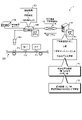
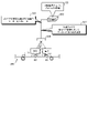
まず、実施形態に係る画像判定方法の概要について、図1および図2を参照して説明する。図1は、実施形態に係る画像判定方法の概要説明図(その1)である。また、図2は、実施形態に係る画像判定方法の概要説明図(その2)である。 First, an outline of an image determination method according to an embodiment will be described with reference to FIGS. 1 and 2. FIG. FIG. 1 is a schematic explanatory diagram (Part 1) of an image determination method according to an embodiment. FIG. 2 is a schematic explanatory diagram (part 2) of the image determination method according to the embodiment.
なお、以下では、製造ラインにおいて製品として丸形のクッキーが製造され、かかるクッキーの出荷前検査等において、欠けや焦げ、割れなどのある不良品を検知する場合を例に挙げて説明を行う。また、以下では、画像判定用の判定モデルが、深層学習ネットワークであるものとする。 In the following description, round cookies are manufactured as a product on a manufacturing line, and defective products with chips, scorches, cracks, etc. are detected in pre-shipment inspections of such cookies. In the following description, it is assumed that the determination model for image determination is a deep learning network.
図1に示すように、実施形態に係る画像判定システム1は、学習装置10と、画像判定装置100と、プロジェクタ制御装置200とを含む。
As shown in FIG. 1, the image determination system 1 according to the embodiment includes a
画像判定装置100およびプロジェクタ制御装置200は、いわゆるエッジコンピューティングにおけるエッジプラットフォームに相当する装置であり、カメラ150、コンベア装置300、プロジェクタ400(図2参照)等を含む製造ラインに設けられる。
The
学習装置10は、イントラネットやインターネット、携帯電話回線網等のネットワークNを介して製造ラインと通信可能に設けられる。学習装置10は、主たる機能として、たとえば製造ラインから学習用画像を収集し、収集した学習用画像を分類して学習用データセットを生成し、かかるデータセットを用いた深層学習により判定モデルを学習する(機能F1)。また、学習装置10は、ネットワークNを介し、学習した判定モデルを画像判定装置100へ配信する。
The
画像判定装置100は、コンベア装置300を流れるクッキーP1,P2,P3…の画像を取得し、学習装置10によって学習された判定モデルを用いて画像判定を行い、学習装置10およびプロジェクタ制御装置200に対し、判定結果を出力する(機能F2)。
たとえば、図1には、画像判定装置100が画像判定により、クッキーP1は「欠け」のある不良品であり、クッキーP2は「焦げ」のある不良品であると判定した例を示している。なお、判定結果は少なくとも、判定された画像の分類クラスおよびそのスコア(類似度、確度等)を含む。
For example, FIG. 1 shows an example in which the
また、学習装置10に対する判定結果には、実際に判定された画像が学習用画像として含まれる。学習装置10は、かかる判定結果を、たとえばオペレータ(「ユーザ」の一例に相当)等の人手を介して検証し、誤判定等があれば、判定精度の向上のために学習用画像を再分類して判定モデルを再学習する。
In addition, the determination result for the
このようなフィードバックを繰り返すことにより、画像判定システム1は、判定モデルの判定精度を向上させることができる。 By repeating such feedback, the image determination system 1 can improve the determination accuracy of the determination model.
ところで、既に述べたが、深層学習ネットワークは、言わば一種の関数であり、ブラックボックスである。このため、従来は、誤判定が生じた場合などに、学習用画像を再分類して判定モデルの再学習を行いたくとも、そもそもの判定根拠が不明確なため、適切に学習用画像を再分類することが難しかった。 By the way, as already mentioned, a deep learning network is, so to speak, a kind of function, a black box. For this reason, conventionally, when an erroneous judgment occurs, even if it is desired to reclassify the training images and re-learn the judgment model, the basis for the judgment is unclear in the first place. It was difficult to categorize.
また、判定精度の向上のためには、大量の学習用画像を用いて判定モデルを学習し、かかる判定モデルを大量の検証用画像を用いて検証することが望ましいが、従来は、その検証の多くをオペレータ等が目視で行う必要があり、煩雑であった。 In addition, in order to improve the accuracy of determination, it is desirable to learn a determination model using a large number of training images and to verify the determination model using a large amount of verification images. Many of them had to be visually checked by an operator, which was troublesome.
そこで、実施形態に係る画像判定方法では、製造ラインにおける製品の画像を取得し、深層学習ネットワークである判定モデルを用いて分類判定し、上記画像が判定モデルへ入力された場合の上記画像に対する判定モデルの着目点を抽出して可視化することによって判定モデルの判定結果を解析し、上記画像が判定モデルへ入力された場合の高次元空間における上記画像の特徴量を次元圧縮による低次元表現へ変換して可視化することによって判定モデルの判定結果を解析し、着目点抽出および次元圧縮による解析結果に基づいて分類された上記画像に基づいて判定モデルを学習することとした。 Therefore, in the image determination method according to the embodiment, an image of a product in a manufacturing line is acquired, a classification determination is performed using a determination model that is a deep learning network, and the image is determined when the image is input to the determination model. Analyzing the judgment result of the judgment model by extracting and visualizing the points of interest of the model, and converting the feature amount of the image in the high-dimensional space when the image is input to the judgment model into a low-dimensional representation by dimensional compression. The judgment model is analyzed by visualizing it as a model, and the judgment model is learned based on the images classified based on the analysis results obtained by extracting the point of interest and dimensionality reduction.
具体的には、図1に示すように、実施形態に係る画像判定方法では、学習装置10が、2つの手法により判定モデルの判定結果を解析する(ステップS1)。第1の手法では、学習装置10は、勾配荷重クラス活性化マッピング手法(Grad-CAM:Gradient-weighted Class Activation Mapping)を用いた「着目点抽出」により、判定モデルによる判定根拠を可視化する。
Specifically, as shown in FIG. 1, in the image determination method according to the embodiment, the
これにより、オペレータは、判定モデルが「どこを見て分類(判定)したか」を一目で把握できるようになるため、たとえば誤判定している場合に、対象画像を適切に分類し直すことが可能となる。なお、かかる第1の手法による可視化の具体例については、図5および図6を用いた説明で後述する。 As a result, the operator can grasp at a glance "where the judgment model was classified (judgment)". It becomes possible. A specific example of visualization by the first method will be described later with reference to FIGS. 5 and 6. FIG.
また、第2の手法では、学習装置10は、UMAP(Uniform Manifold Approximation and Projection)を用いた「次元圧縮」(次元削減とも言う)により、判定結果をより見やすい形で可視化する。
In the second method, the
UMAPは、機械学習による非線形次元圧縮手法であり、リーマン幾何学と代数トポロジーに基づき、高次元空間のデータ構造を保ち、トポロジー間のクロス・エントロピーを最小にしながら低次元のデータに変換する。すなわち、実施形態に係る画像判定方法では、かかるUMAPを用いて、画像が判定モデルへ入力された場合の高次元空間における画像の特徴量を次元圧縮による低次元表現へ変換して可視化する。 UMAP is a non-linear dimensionality compression technique based on machine learning, based on Riemannian geometry and algebraic topology, which preserves the data structure of high-dimensional space and converts it to low-dimensional data while minimizing cross-entropy between topologies. That is, in the image determination method according to the embodiment, UMAP is used to convert the feature amount of the image in the high-dimensional space when the image is input to the determination model into a low-dimensional expression by dimensional compression and visualize it.
このため、第2の手法によれば、低次元の埋め込み空間に、判定結果の分布をよりバラツキの少ない形で明示することが可能となり、誤判定している画像をオペレータが一目で分かるように可視化することが可能となる。かかる第2の手法による可視化の具体例については、図7~図9を用いた説明で後述する。 For this reason, according to the second method, it is possible to express the distribution of judgment results in a low-dimensional embedding space in a form with less variation. Visualization becomes possible. A specific example of visualization by the second method will be described later with reference to FIGS. 7 to 9. FIG.
そして、学習装置10は、かかる2つの手法による解析結果に基づき、学習用画像を再分類して再学習を行い(ステップS2)、再学習した判定モデルを画像判定装置100へ配信する。そして、画像判定装置100は、再学習された判定モデルを用いて、以降の画像判定を行うこととなる。
Then, the
したがって、実施形態に係る画像判定方法によれば、効率よく判定精度の向上を図ることができる。 Therefore, according to the image determination method according to the embodiment, it is possible to efficiently improve the determination accuracy.
一方、プロジェクタ制御装置200は、製造ラインに設けられたプロジェクタ400を制御する装置である。具体的には、図2に示すように、実施形態に係る画像判定方法では、プロジェクタ制御装置200は、画像判定装置100の判定結果に応じたプロジェクタ投影を行う。
On the other hand, the
より具体的には、プロジェクタ制御装置200は、コンベア装置300を流れるクッキーP1,P2,P3…に対し、プロジェクタ400によりマーカーを投影させる(ステップS3)。
More specifically,
このとき、プロジェクタ制御装置200は、コンベア装置300のコンベアの搬送速度と同じ速度でマーカーをスクロールさせる(ステップS31)。言い換えれば、プロジェクタ制御装置200は、マーカーが対象のクッキーP1,P2,P3…をトラッキングするように、プロジェクタ400によりマーカーを投影させる。
At this time, the
また、プロジェクタ制御装置200は、分類クラスや取るべき処置に応じて、マーカーの色や形を変更させる(ステップS32)。たとえば、プロジェクタ制御装置200は、分類クラスが「欠け」のクッキーP1と、「焦げ」のクッキーP2とで、マーカーの色や形を変更させる。
Also, the
また、たとえば、プロジェクタ制御装置200は、「コンベアから除去すべき」や、「生産へフィードバックすべき」といった取るべき処置に応じて、マーカーの色や形を変更させる。また、プロジェクタ制御装置200は、判定結果に含まれる上述のスコアに応じて、「AIが判定に悩んだもの」、すなわちスコアがグレーゾーンのものに、それと分かるマーカーを投影し、ライン担当者の目視によるチェックを促すようにしてもよい。
Also, for example, the
これにより、実施形態に係る画像判定方法によれば、判定モデルの高い判定精度に応じて、その結果を適切に製造ラインに反映させることが可能となる。なお、プロジェクタ制御装置200は、「判定結果反映装置」の一例である。したがって、判定結果反映装置は、製造ラインに設けられ、画像判定装置100の判定結果を反映すべき他の装置であってもよい。たとえば、判定結果反映装置は、画像判定装置100の判定結果に応じて火加減を調節するクッキーのベイク装置等であってもよい。
Thus, according to the image determination method according to the embodiment, it is possible to appropriately reflect the result on the production line according to the high determination accuracy of the determination model. Note that the
以下、上述した実施形態に係る画像判定方法を適用した画像判定システム1の構成について、さらに具体的に説明する。 The configuration of the image determination system 1 to which the image determination method according to the above-described embodiment is applied will now be described more specifically.
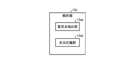
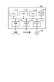
図3は、実施形態に係る学習装置10のブロック図である。また、図4は、解析部13dのブロック図である。なお、図3、図4、および、後に示す図10,11では、本実施形態の特徴を説明するために必要な構成要素を機能ブロックで表しており、一般的な構成要素についての記載を省略している。
FIG. 3 is a block diagram of the
換言すれば、図3、図4、図10および図11に図示される各構成要素は機能概念的なものであり、必ずしも物理的に図示の如く構成されていることを要しない。たとえば、各機能ブロックの分散・統合の具体的形態は図示のものに限られず、その全部または一部を、各種の負荷や使用状況等に応じて、任意の単位で機能的または物理的に分散・統合して構成することが可能である。 In other words, each component illustrated in FIGS. 3, 4, 10 and 11 is functionally conceptual and does not necessarily need to be physically configured as illustrated. For example, the specific forms of distribution and integration of each functional block are not limited to those shown in the figure, and all or part of them can be functionally or physically distributed in arbitrary units according to various loads and usage conditions.・It is possible to integrate and configure.
なお、図3、図4、図10および図11を用いた説明では、これまでに既に述べた構成要素については、説明を簡略するか、省略する場合がある。 In the explanation using FIGS. 3, 4, 10 and 11, the explanation of the components already described may be simplified or omitted in some cases.
図3に示すように、実施形態に係る学習装置10は、通信部11と、記憶部12と、制御部13とを備える。また、学習装置10は、操作部3と、表示部5とが接続される。操作部3は、キーボードやマウス、タッチパネル等によって実現される。表示部5は、ディスプレイ等によって実現される。
As shown in FIG. 3 , the
通信部11は、たとえば、NIC(Network Interface Card)等によって実現される。通信部11は、ネットワークNに対し有線または無線で接続され、画像判定装置100を含む製造ラインとの間で情報の送受信を行う。
The
記憶部12は、たとえば、RAM(Random Access Memory)、ROM(Read Only Memory)、フラッシュメモリ(Flash Memory)等の半導体メモリ素子、または、ハードディスク、光ディスク等の記憶装置によって実現される。図3に示す例では、記憶部12は、収集情報データベース(DB)12aと、学習用データセット12bと、判定モデル12cとを記憶する。
The
収集情報データベース12aは、通信部11を介し、後述する収集部13aによって収集される判定結果を含む各種のデータが格納されるデータベースである。学習用データセット12bは、収集情報データベース12aへ格納された判定結果、および、操作部3を介したオペレータの操作等に基づき、後述する分類部13bによって分類クラスごとに分類された学習用画像のデータセットである。判定モデル12cは、後述する学習部13cによって学習される深層学習ネットワークである。
The collected
制御部13は、コントローラ(controller)であり、たとえば、CPU(Central Processing Unit)やMPU(Micro Processing Unit)等によって、記憶部12に記憶されている図示略の各種プログラムがRAMを作業領域として実行されることにより実現される。また、制御部13は、たとえば、ASIC(Application Specific Integrated Circuit)やFPGA(Field Programmable Gate Array)等の集積回路により実現することができる。
The
制御部13は、収集部13aと、分類部13bと、学習部13cと、解析部13dと、表示制御部13eと、配信部13fとを有し、以下に説明する情報処理の機能や作用を実現または実行する。
The
収集部13aは、通信部11を介し、画像判定装置100からの判定結果を収集する。また、収集部13aは、収集した判定結果を収集情報データベース12aへ格納する。
The
分類部13bは、収集情報データベース12aへ格納された判定結果、および、操作部3を介したオペレータの操作等に基づき、学習用画像を「正常」、「欠け」、「焦げ」、「割れ」といった分類クラスごとに分類し、学習用データセット12bを生成する。学習部13cは、学習用データセット12bに基づき、判定モデル12cを学習する。
Based on the determination result stored in the collected
解析部13dは、収集情報データベース12aへ格納された判定結果、および、判定モデル12cに基づき、上述した第1の手法および第2の手法によって判定結果を解析する。図4に示すように、解析部13dは、着目点抽出部13daと、次元圧縮部13dbとを有する。
The
着目点抽出部13daは、上述したGrad-CAMを用いた着目点抽出により、学習用画像を判定モデル12cへ入力したときの判定モデル12cによる判定根拠を可視化する。
The point-of-interest extraction unit 13da extracts the point of interest using Grad-CAM as described above, and visualizes the basis for determination by the
次元圧縮部13dbは、上述したUMAPを用いた次元圧縮により、低次元の埋め込み空間に、判定結果の分布を可視化する。なお、UMAPは、次元圧縮手法の一例であり、他の手法を用いることを限定するものではない。たとえば、主成分分析や、t分布型確率的近傍埋め込み法(t-SNE:t-distributed Stochastic Neighbor Embedding)等を用いてもよいが、計算速度は、UMAPがより高速である。 The dimension compression unit 13db visualizes the distribution of the determination results in the low-dimensional embedding space by the dimension compression using UMAP described above. Note that UMAP is an example of a dimension compression method, and the use of other methods is not limited. For example, principal component analysis, t-distributed stochastic neighbor embedding (t-SNE), etc. may be used, but UMAP is faster in terms of calculation speed.
ここで、着目点抽出部13daおよび次元圧縮部13dbによる可視化の具体例について、図5~図9を用いて説明する。図5は、着目点抽出部13daによる可視化の具体例の説明図(その1)である。また、図6は、着目点抽出部13daによる可視化の具体例の説明図(その2)である。 Here, specific examples of visualization by the point-of-interest extraction unit 13da and the dimension compression unit 13db will be described with reference to FIGS. 5 to 9. FIG. FIG. 5 is an explanatory diagram (Part 1) of a specific example of visualization by the point-of-interest extraction unit 13da. FIG. 6 is an explanatory diagram (part 2) of a specific example of visualization by the point-of-interest extraction unit 13da.
また、図7は、次元圧縮部13dbによる可視化の具体例の説明図(その1)である。また、図8は、次元圧縮部13dbによる可視化の具体例の説明図(その2)である。また、図9は、次元圧縮部13dbによる可視化の具体例の説明図(その3)である。 FIG. 7 is an explanatory diagram (part 1) of a specific example of visualization by the dimension compression unit 13db. FIG. 8 is an explanatory diagram (part 2) of a specific example of visualization by the dimension compression unit 13db. FIG. 9 is an explanatory diagram (part 3) of a specific example of visualization by the dimension compression unit 13db.
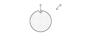
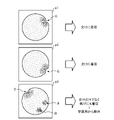
まず、図6を用いた説明では、図5に示すように、判定モデル12cが、欠けCがあると判定するクッキーPの画像について考える。着目点抽出部13daは、このような欠けCがあると判定される画像p1,p2,p3…を判定モデル12cへ入力し、欠けCがあると判定された判定根拠を可視化する。
First, in the description using FIG. 6, as shown in FIG. 5, consider an image of a cookie P for which the
深層学習ネットワークは、畳み込み層とプーリング層を何層にもわたって積み重ねた特徴抽出部と、その特徴量出力を受け取ってクラスラベルと照合して教師あり学習を行う識別部との2つの部分に分けられる。また、識別部は通常、全結合の多層ニューラルネットワークで構成され、その最終層は特徴量を各分類クラスのスコアに変換するソフトマックス層になっている。 A deep learning network consists of two parts: a feature extraction part that stacks many layers of convolution layers and pooling layers, and a classification part that receives the feature value output and compares it with class labels to perform supervised learning. divided. In addition, the classifier is usually composed of a fully-connected multi-layer neural network, the final layer of which is a softmax layer that converts the feature quantity into a score for each classification class.
スコアは、入力画像に各分類クラスのタグが付与される確率(類似度と言い換えても可)や確度である。判定モデル12cによる判定結果は、かかるスコアが最大となる分類クラスである。
The score is the probability (can also be referred to as similarity) or certainty that the tag of each classification class is assigned to the input image. The determination result of the
着目点抽出部13daは、Grad-CAMにより、分類クラスごとのスコアへの影響が大きい画像箇所を微分係数(勾配と言い換えても可)の平均化によって特定し、ヒートマップ化する。 The point-of-interest extracting unit 13da uses Grad-CAM to identify image locations that greatly affect the score for each classification class by averaging differential coefficients (which can be called gradients), and converts them into a heat map.
図6には、かかるヒートマップの例を示している。図6の例では、画像p1,p2については、欠けCの部分のみがヒートマップ化され、判定モデル12cが、まさに欠けCに着目して欠けCがあると判定していることが分かる。したがって、画像p1,p2は、分類クラス「欠け」の学習用画像として適していることが一目で分かる。
FIG. 6 shows an example of such a heat map. In the example of FIG. 6, for images p1 and p2, only the portion of chipping C is heatmapped, and it can be seen that the
一方で、画像p3については、欠けCの部分だけでなく、焦げBの部分もヒートマップ化され、判定モデル12cが、欠けCだけでなく焦げBにも着目していることが分かる。言い換えれば、画像p3は、分類クラス「欠け」の学習用画像としては、ノイズ成分を含むものであることが一目で分かる。こうした場合に、かかるヒートマップは、オペレータに、画像p3が分類クラス「欠け」の学習用画像としては適さないとして、学習用から除外させることができる。これにより、効率よく判定精度の向上に資することができる。 On the other hand, for the image p3, not only the chipped portion C but also the burnt portion B are heat-mapped. In other words, it can be seen at a glance that the image p3 contains noise components as a learning image of the classification class “missing”. In such a case, such a heat map can cause the operator to exclude image p3 from training as it is not suitable as a training image for the classification class "missing". As a result, it is possible to efficiently improve the determination accuracy.
また、図7~図9に示すように、次元圧縮部13dbは、たとえば判定モデル12cの高次元空間の特徴量マップを低次元(ここでは、3次元)に次元圧縮し、低次元の埋め込み空間に判定結果の分布を可視化する。また、次元圧縮部13dbは、かかる可視化情報を、オペレータに操作可能なGUI(Graphic User Interface)ツールとして生成する。
Further, as shown in FIGS. 7 to 9, the dimension compression unit 13db dimension-compresses, for example, the high-dimensional space feature quantity map of the
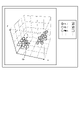
たとえば、図7に示すように、次元圧縮部13dbは、各判定結果に対応するチェックボックスを有するGUIツールを生成する。かかるGUIツールにおいて、図7に示すように、「欠け」および「焦げ」がチェックされたものとする。 For example, as shown in FIG. 7, the dimension compression unit 13db generates a GUI tool having check boxes corresponding to each determination result. It is assumed that "missing" and "burning" are checked in such a GUI tool as shown in FIG.
すると、図7に示すように、「欠け」の判定結果を受けた各画像と、「焦げ」の判定を受けた各画像との、次元圧縮された低次元空間における分布が可視化される。なお、図中の低次元空間における丸印の各々は、各画像に対応しており、次元圧縮部13dbは、オペレータがその一つ一つを選択可能となるようにGUIツールを生成する。 Then, as shown in FIG. 7, the distribution in the dimensionally compressed low-dimensional space of each image determined as "missing" and each image determined as "burned" is visualized. Each circle in the low-dimensional space in the drawing corresponds to each image, and the dimension compression unit 13db generates a GUI tool so that the operator can select one of them.
ここで、図中のカーソルCrが指すように、たとえば「欠け」と判定されているものの、特徴量としては「欠け」よりも「焦げ」の方にきわめて近い画像があり、オペレータがこれを選択したものとする。 Here, as indicated by the cursor Cr in the figure, there is an image that is determined to be, for example, "missing", but the feature amount is much closer to "burnt" than "missing", and the operator selects this image. shall be
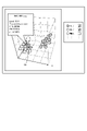
すると、図8に示すように、次元圧縮部13dbは、かかる画像のファイル名や分類クラスのラベル名といった画像の詳細情報が示されるようにGUIツールを生成する。同図の場合、その詳細情報によれば、該当の画像「IMG_1001.png」が分類クラス「欠け」であるにも関わらず、その特徴量は「焦げ」にきわめて近いため、本来であれば該当の画像が「焦げ」と判定されるべき誤判定であることが分かる。 Then, as shown in FIG. 8, the dimension compression unit 13db generates a GUI tool so that detailed information about the image, such as the file name of the image and the label name of the classification class, is displayed. In the case of the same figure, according to the detailed information, although the corresponding image "IMG_1001.png" is classified as "missing", its feature value is very close to "burnt". is an erroneous determination that should be determined as "burnt".
したがって、オペレータは、かかるGUIツールにより、誤判定を一目で把握することができる。そして、オペレータは、分類部13bに該当の画像の分類をやり直させたうえで、学習部13cが判定モデル12cを学習することにより、判定モデル12cの判定精度を向上させることができる。
Therefore, the operator can grasp the erroneous judgment at a glance by such a GUI tool. Then, the operator causes the
なお、図9に示すように、GUIツールにおいて、さらに「割れ」のチェックボックスがチェックされた場合には、低次元空間にさらに「割れ」の各画像の分布が可視化されることとなる。また、図7~図9には図示していないが、オペレータは、GUIツール上の低次元空間を任意に360°回転させたり、拡大したり、縮小したりすることが可能である。 As shown in FIG. 9, when the "crack" check box is further checked in the GUI tool, the distribution of each "crack" image is further visualized in the low-dimensional space. Also, although not shown in FIGS. 7 to 9, the operator can arbitrarily rotate the low-dimensional space on the GUI tool by 360°, enlarge it, and reduce it.
図3の説明に戻る。表示制御部13eは、解析部13dの解析結果を表示部5に表示させる。表示部5から操作部3へ破線の矢印で示すように、オペレータが、図5~図9に示したような解析部13dの解析結果に基づいて再分類を指示すると、分類部13bは、学習用データセット12bの学習用画像を再分類し、学習部13cに判定モデル12cを学習させる。
Returning to the description of FIG. The
配信部13fは、通信部11を介し、学習部13cによって学習された判定モデル12cを画像判定装置100へ配信する。
The
次に、画像判定装置100の構成について説明する。図10は、実施形態に係る画像判定装置100のブロック図である。
Next, the configuration of the
図10に示すように、実施形態に係る画像判定装置100は、通信部101と、記憶部102と、制御部103とを備える。
As shown in FIG. 10, the
通信部101は、上述した通信部11と同様に、たとえば、NIC等によって実現される。通信部101は、ネットワークN、カメラ150およびプロジェクタ制御装置200に対し有線または無線で接続され、学習装置10、カメラ150およびプロジェクタ制御装置200との間で情報の送受信を行う。
The
記憶部102は、上述した記憶部12と同様に、たとえば、RAM、ROM、フラッシュメモリ等の半導体メモリ素子、または、ハードディスク、光ディスク等の記憶装置によって実現される。図10に示す例では、記憶部102は、判定モデル102aを記憶する。判定モデル102aは、学習装置から配信される判定モデル12cに相当する。
The
制御部103は、上述した制御部13と同様に、コントローラであり、たとえば、CPUやMPU等によって、記憶部102に記憶されている図示略の各種プログラムがRAMを作業領域として実行されることにより実現される。また、制御部103は、上述した制御部13と同様に、たとえば、ASICやFPGA等の集積回路により実現することができる。
The control unit 103 is a controller similar to the
制御部103は、取得部103aと、判定部103bと、出力部103cとを有し、以下に説明する情報処理の機能や作用を実現または実行する。
The control unit 103 has an
取得部103aは、通信部101を介し、学習装置10から配信される判定モデル12cを取得し、判定モデル102aとして記憶部102へ記憶させる。また、取得部103aは、通信部101を介し、カメラ150によって撮影されるクッキーPの画像を取得し、判定部103bへ出力する。
判定部103bは、取得部103aによって取得された画像を判定モデル102aへ入力し、判定モデル102aから判定結果を取得する。また、判定部103bは、取得した判定結果を出力部103cへ出力する。
The
出力部103cは、通信部101を介し、判定部103bからの判定結果を学習装置10およびプロジェクタ制御装置200に対し出力する。
The
次に、プロジェクタ制御装置200の構成について説明する。図11は、実施形態に係るプロジェクタ制御装置200のブロック図である。
Next, the configuration of the
図11に示すように、実施形態に係るプロジェクタ制御装置200は、通信部201と、記憶部202と、制御部203とを備える。
As shown in FIG. 11, the
通信部201は、上述した通信部11,101と同様に、たとえば、NIC等によって実現される。通信部201は、画像判定装置100およびコンベア装置300に対し有線または無線で接続され、画像判定装置100およびコンベア装置300との間で情報の送受信を行う。
The
記憶部202は、上述した記憶部12,102と同様に、たとえば、RAM、ROM、フラッシュメモリ等の半導体メモリ素子、または、ハードディスク、光ディスク等の記憶装置によって実現される。図11に示す例では、記憶部202は、投影設定情報202aを記憶する。投影設定情報202aは、画像判定装置100からの判定結果に応じたマーカーの投影に関する設定情報である。
The
制御部203は、上述した制御部13,103と同様に、コントローラであり、たとえば、CPUやMPU等によって、記憶部202に記憶されている図示略の各種プログラムがRAMを作業領域として実行されることにより実現される。また、制御部203は、上述した制御部13,103と同様に、たとえば、ASICやFPGA等の集積回路により実現することができる。
The
制御部203は、取得部203aと、投影制御部203bとを有し、以下に説明する情報処理の機能や作用を実現または実行する。
The
取得部203aは、通信部201を介し、画像判定装置100から出力される判定結果を取得し、投影制御部203bへ出力する。また、取得部203aは、通信部201を介し、コンベア装置300からコンベアの搬送速度を取得し、投影制御部203bへ出力する。
The
投影制御部203bは、取得部203aによって取得された判定結果、搬送速度および投影設定情報202aに基づき、プロジェクタ400によるマーカーの投影を制御する。
The
次に、実施形態に係る画像判定システム1が実行する処理手順について、図12を用いて説明する。図12は、実施形態に係る画像判定装置100が実行する処理手順を示す処理シーケンスである。
Next, a processing procedure executed by the image determination system 1 according to the embodiment will be described with reference to FIG. 12 . FIG. 12 is a processing sequence showing a processing procedure executed by the
図12に示すように、まず画像判定システム1の運用前等において、学習装置10が学習用画像を収集する(ステップS101)。そして、学習装置10は、学習用画像を分類し(ステップS102)、学習用データセット12bを生成する(ステップS103)。
As shown in FIG. 12, before the image determination system 1 is operated, the
そして、学習装置10は、学習用データセット12bを用いて判定モデル12cを学習し(ステップS104)、画像判定装置100へ判定モデル12cを配信する(ステップS105)。
Then, the
画像判定装置100は、カメラ150によって撮影された画像を取得し(ステップS106)、判定モデル102aを用いて画像を判定する(ステップS107)。そして、判定結果を学習装置10およびプロジェクタ制御装置200へ出力する(ステップS108,S109)。
The
学習装置10は、画像判定装置100からの判定結果を収集し(ステップS110)、着目点抽出による解析(ステップS111)、および、次元圧縮による解析(ステップS112)を実行する。
The
そして、学習装置10は、それらの解析結果に基づき、学習用画像を再分類させる(ステップS113)。そして、ステップS104からの処理を繰り返す。
Then, the
一方、プロジェクタ制御装置200は、画像判定装置100からの判定結果に応じたプロジェクタ投影を行うことを繰り返す(ステップS114)。
On the other hand, the
なお、上述してきた実施形態に係る学習装置10、画像判定装置100およびプロジェクタ制御装置200は、たとえば図13に示すような構成のコンピュータ1000によって実現される。学習装置10を例に挙げて説明する。図13は、学習装置10の機能を実現するコンピュータの一例を示すハードウェア構成図である。コンピュータ1000は、CPU1100、RAM1200、ROM1300、HDD(Hard Disk Drive)1400、通信インタフェース(I/F)1500、入出力インタフェース(I/F)1600、および、メディアインタフェース(I/F)67を備える。
Note that the
CPU1100は、ROM1300またはHDD1400に格納されたプログラムに基づいて動作し、各部の制御を行う。ROM1300は、コンピュータ1000の起動時にCPU1100によって実行されるブートプログラムや、コンピュータ1000のハードウェアに依存するプログラム等を格納する。
The CPU 1100 operates based on programs stored in the
HDD1400は、CPU1100によって実行されるプログラムおよび当該プログラムによって使用されるデータ等を格納する。通信インタフェース1500は、通信ネットワークを介して他の機器からデータを受信してCPU1100へ送り、CPU1100が生成したデータを、通信ネットワークを介して他の機器へ送信する。
CPU1100は、入出力インタフェース1600を介して、ディスプレイやプリンタ等の出力装置、および、キーボードやマウス等の入力装置を制御する。CPU1100は、入出力インタフェース1600を介して、入力装置からデータを取得する。また、CPU1100は、生成したデータを、入出力インタフェース1600を介して出力装置へ出力する。
The CPU 1100 controls output devices such as displays and printers, and input devices such as keyboards and mice, via an input/
メディアインタフェース1700は、記録媒体1800に格納されたプログラムまたはデータを読み取り、RAM1200を介してCPU1100に提供する。CPU1100は、当該プログラムを、メディアインタフェース1700を介して記録媒体1800からRAM1200上にロードし、ロードしたプログラムを実行する。記録媒体1800は、たとえばDVD(Digital Versatile Disc)、PD(Phase change rewritable Disk)等の光学記録媒体、MO(Magneto-Optical disk)等の光磁気記録媒体、テープ媒体、磁気記録媒体、または、半導体メモリ等である。
たとえば、コンピュータ1000が実施形態に係る学習装置10として機能する場合、コンピュータ1000のCPU1100は、RAM1200上にロードされたプログラムを実行することにより、制御部13の各機能を実現する。また、HDD1400には、記憶部12内のデータが記憶される。コンピュータ1000のCPU1100は、これらのプログラムを、記録媒体1800から読み取って実行するが、他の例として、他の装置から、通信ネットワークを介してこれらのプログラムを取得してもよい。
For example, when
上述してきたように、実施形態に係る画像判定システム1は、判定部103bと、着目点抽出部13da(「第1の解析部」の一例に相当)と、次元圧縮部13db(「第2の解析部」の一例に相当)と、学習部13cとを含む。判定部103bは、製造ラインにおける製品の画像を取得し、深層学習ネットワークである判定モデルを用いて分類判定する。着目点抽出部13daは、上記画像が判定モデルへ入力された場合の上記画像に対する判定モデルの着目点を抽出して可視化することによって判定モデルの判定結果を解析する。次元圧縮部13dbは、上記画像が判定モデルへ入力された場合の高次元空間における上記画像の特徴量を次元圧縮による低次元表現へ変換して可視化することによって判定モデルの判定結果を解析する。学習部13cは、着目点抽出部13daおよび次元圧縮部13dbによる解析結果に基づいて分類された上記画像に基づいて判定モデルを学習する。
As described above, the image determination system 1 according to the embodiment includes the
したがって、実施形態に係る画像判定システム1によれば、効率よく判定精度の向上を図ることができる。 Therefore, according to the image determination system 1 according to the embodiment, it is possible to efficiently improve the determination accuracy.
なお、上述した実施形態では、学習用画像の再分類に際し、オペレータの操作を要することとしたが、これに限られるものではなく、解析部13dの解析結果に基づいて分類部13bが自動的に再分類を行うようにしてもよい。 In the above-described embodiment, an operator's operation is required to reclassify the learning images, but the present invention is not limited to this. Reclassification may be performed.
かかる場合、分類部13bは、たとえば解析部13dが可視化したヒートマップや低次元空間マップを画像解析する画像解析機能を有し、その画像解析結果に基づいて学習用画像の再分類を行うこととなる。
In such a case, the
また、上述した実施形態では、着目点抽出のアルゴリズムとしてGrad-CAMを用いることしたが、これに限られるものではなく、たとえばGuided Backpropagationの結果にGrad-CAMの出力を重ねるGuided Grad-CAMと呼ばれるアルゴリズム等を用いることとしてもよい。 Further, in the above-described embodiment, Grad-CAM is used as an algorithm for extracting the point of interest, but it is not limited to this. An algorithm or the like may be used.
また、上述した実施形態では、製造ラインにおける製品がクッキーPであることとしたが、無論、製品の種別を限定するものではない。 Also, in the above-described embodiment, the product in the production line is the cookie P, but the type of the product is of course not limited.
さらなる効果や変形例は、当業者によって容易に導き出すことができる。このため、本発明のより広範な態様は、以上のように表しかつ記述した特定の詳細および代表的な実施形態に限定されるものではない。したがって、添付の特許請求の範囲およびその均等物によって定義される総括的な発明の概念の精神または範囲から逸脱することなく、様々な変更が可能である。 Further effects and modifications can be easily derived by those skilled in the art. Therefore, the broader aspects of the invention are not limited to the specific details and representative embodiments so shown and described. Accordingly, various changes may be made without departing from the spirit or scope of the general inventive concept defined by the appended claims and equivalents thereof.
1 画像判定システム
10 学習装置
12c 判定モデル
13 制御部
13a 収集部
13b 分類部
13c 学習部
13d 解析部
13da 着目点抽出部
13db 次元圧縮部
13e 表示制御部
13f 配信部
100 画像判定装置
102a 判定モデル
103 制御部
103a 取得部
103b 判定部
103c 出力部
200 プロジェクタ制御装置
203 制御部
203a 取得部
203b 投影制御部
300 コンベア装置
400 プロジェクタ
1
Claims (10)
前記画像が前記判定モデルへ入力された場合の前記画像に対する前記判定モデルの着目点を抽出して可視化することによって前記判定モデルの判定結果を解析する第1の解析工程と、
前記画像が前記判定モデルへ入力された場合の高次元空間における前記画像の特徴量を次元圧縮による低次元表現へ変換して可視化することによって前記判定モデルの判定結果を解析する第2の解析工程と、
前記第1の解析工程および前記第2の解析工程における解析結果に基づいて分類された前記画像に基づいて前記判定モデルを学習する学習工程と
を含むことを特徴とする画像判定方法。 A judgment step of acquiring an image of a product in a manufacturing line and classifying it using a judgment model that is a deep learning network;
a first analysis step of analyzing a determination result of the determination model by extracting and visualizing a focus point of the determination model with respect to the image when the image is input to the determination model;
a second analysis step of analyzing the determination result of the determination model by converting the feature amount of the image in a high-dimensional space when the image is input to the determination model into a low-dimensional representation by dimensional compression and visualizing the image. When,
and a learning step of learning the judgment model based on the images classified based on the analysis results of the first analysis step and the second analysis step.
前記第1の解析工程において、一つの前記画像について異なる複数の分類クラスに対応する前記着目点が抽出された場合に、当該画像を学習用画像から除外して前記判定モデルを学習する
ことを特徴とする請求項1に記載の画像判定方法。 The learning step includes:
wherein, in the first analysis step, when the points of interest corresponding to a plurality of different classification classes are extracted for one of the images, the image is excluded from learning images and the judgment model is learned. The image determination method according to claim 1, wherein
前記低次元表現による前記判定モデルの判定結果の分布をGUI化し、該GUIを介してユーザに前記画像を分類させる
ことを特徴とする請求項1または2に記載の画像判定方法。 The second analysis step includes
3. The image determination method according to claim 1, wherein the distribution of determination results of the determination model based on the low-dimensional representation is made into a GUI, and a user is allowed to classify the images via the GUI.
Grad-CAMを用いて前記着目点を抽出して可視化する
ことを特徴とする請求項1、2または3に記載の画像判定方法。 The first analysis step includes
4. The image determination method according to claim 1, wherein the point of interest is extracted and visualized using a Grad-CAM.
UMAPを用いた前記次元圧縮により前記画像の特徴量を前記低次元表現へ変換して可視化する
ことを特徴とする請求項1~4のいずれか一つに記載の画像判定方法。 The second analysis step includes
The image determination method according to any one of claims 1 to 4, wherein the feature amount of the image is converted into the low-dimensional representation by the dimensional compression using UMAP and visualized.
をさらに含むことを特徴とする請求項1~5のいずれか一つに記載の画像判定方法。 The image determination method according to any one of claims 1 to 5, further comprising a determination result reflecting step of reflecting the determination result of the determination model on the production line.
当該製造ライン上の前記製品に対してマーカーを投影するプロジェクタを有しており、
前記判定結果反映工程は、
前記製品の分類クラスおよび取るべき処置に応じて、少なくとも前記マーカーの色および形を変更させる
ことを特徴とする請求項6に記載の画像判定方法。 The production line is
Having a projector that projects a marker onto the product on the production line,
The determination result reflection step includes:
7. The image determination method according to claim 6, wherein at least the color and shape of the marker are changed according to the classification class of the product and the action to be taken.
前記製品の搬送速度と同じ速度で前記マーカーをスクロールさせる
ことを特徴とする請求項7に記載の画像判定方法。 The determination result reflection step includes:
8. The image determination method according to claim 7, wherein the marker is scrolled at the same speed as the conveying speed of the product.
前記画像が前記判定モデルへ入力された場合の前記画像に対する前記判定モデルの着目点を抽出して可視化することによって前記判定モデルの判定結果を解析する第1の解析部と、
前記画像が前記判定モデルへ入力された場合の高次元空間における前記画像の特徴量を次元圧縮による低次元表現へ変換して可視化することによって前記判定モデルの判定結果を解析する第2の解析部と、
前記第1の解析部および前記第2の解析部による解析結果に基づいて分類された前記画像に基づいて前記判定モデルを学習する学習部と
を備えることを特徴とする画像判定システム。 A determination unit that acquires an image of a product in a manufacturing line and uses a determination model that is a deep learning network to make a classification determination;
a first analysis unit that analyzes a determination result of the determination model by extracting and visualizing a focus point of the determination model with respect to the image when the image is input to the determination model;
a second analysis unit for analyzing the determination result of the determination model by converting the feature amount of the image in a high-dimensional space when the image is input to the determination model into a low-dimensional representation by dimensional compression and visualizing the image; When,
and a learning unit that learns the determination model based on the images classified based on the analysis results of the first analysis unit and the second analysis unit.
前記画像が前記判定モデルへ入力された場合の前記画像に対する前記判定モデルの着目点を抽出して可視化することによって前記判定モデルの判定結果を解析する第1の解析手順と、
前記画像が前記判定モデルへ入力された場合の高次元空間における前記画像の特徴量を次元圧縮による低次元表現へ変換して可視化することによって前記判定モデルの判定結果を解析する第2の解析手順と、
前記第1の解析手順および前記第2の解析手順における解析結果に基づいて分類された前記画像に基づいて前記判定モデルを学習する学習手順と
をコンピュータに実行させることを特徴とする画像判定プログラム。 A judgment procedure for acquiring images of products in the manufacturing line and classifying and judging using a judgment model that is a deep learning network;
a first analysis procedure for analyzing a determination result of the determination model by extracting and visualizing a focus point of the determination model for the image when the image is input to the determination model;
A second analysis procedure for analyzing the judgment result of the judgment model by converting the feature amount of the image in a high-dimensional space when the image is input to the judgment model into a low-dimensional representation by dimensional compression and visualizing it. When,
and a learning procedure for learning the judgment model based on the images classified based on the analysis results in the first analysis procedure and the second analysis procedure.
Priority Applications (1)
| Application Number | Priority Date | Filing Date | Title |
|---|---|---|---|
| JP2021021239A JP2022123734A (en) | 2021-02-12 | 2021-02-12 | Image judgment method, image judgment system and image judgment program |
Applications Claiming Priority (1)
| Application Number | Priority Date | Filing Date | Title |
|---|---|---|---|
| JP2021021239A JP2022123734A (en) | 2021-02-12 | 2021-02-12 | Image judgment method, image judgment system and image judgment program |
Publications (1)
| Publication Number | Publication Date |
|---|---|
| JP2022123734A true JP2022123734A (en) | 2022-08-24 |
Family
ID=82940432
Family Applications (1)
| Application Number | Title | Priority Date | Filing Date |
|---|---|---|---|
| JP2021021239A Pending JP2022123734A (en) | 2021-02-12 | 2021-02-12 | Image judgment method, image judgment system and image judgment program |
Country Status (1)
| Country | Link |
|---|---|
| JP (1) | JP2022123734A (en) |
Cited By (2)
| Publication number | Priority date | Publication date | Assignee | Title |
|---|---|---|---|---|
| WO2024161744A1 (en) * | 2023-02-02 | 2024-08-08 | 日東電工株式会社 | Image classification device, image classification method, inspection system, and program |
| WO2025009089A1 (en) * | 2023-07-05 | 2025-01-09 | 三菱電機株式会社 | Information processing device, relearning system, relearning method, and relearning program |
-
2021
- 2021-02-12 JP JP2021021239A patent/JP2022123734A/en active Pending
Cited By (3)
| Publication number | Priority date | Publication date | Assignee | Title |
|---|---|---|---|---|
| WO2024161744A1 (en) * | 2023-02-02 | 2024-08-08 | 日東電工株式会社 | Image classification device, image classification method, inspection system, and program |
| WO2025009089A1 (en) * | 2023-07-05 | 2025-01-09 | 三菱電機株式会社 | Information processing device, relearning system, relearning method, and relearning program |
| JP7642182B1 (en) * | 2023-07-05 | 2025-03-07 | 三菱電機株式会社 | Information processing device, relearning system, relearning method, and relearning program |
Similar Documents
| Publication | Publication Date | Title |
|---|---|---|
| EP4388496B1 (en) | Methods and systems for generating segmentation masks | |
| EP3502966B1 (en) | Data generation apparatus, data generation method, and data generation program | |
| CN109598698B (en) | System, method, and non-transitory computer readable medium for classifying a plurality of items | |
| JP5050607B2 (en) | INSPECTION DEVICE, INSPECTION METHOD, INSPECTION PROGRAM, AND COMPUTER-READABLE RECORDING MEDIUM CONTAINING THE SAME | |
| TW202209153A (en) | Automatic optimization of an examination recipe | |
| JP2020064367A (en) | Abnormality detection device and abnormality detection method | |
| CN119810080A (en) | A stainless steel surface defect detection method based on machine vision | |
| US20150242761A1 (en) | Interactive visualization of machine-learning performance | |
| CN113590396A (en) | Method and system for diagnosing defect of primary device, electronic device and storage medium | |
| CN101097564A (en) | Parameter learning method and equipment, and pattern recognition method and equipment | |
| WO2004111934A2 (en) | Segmentation and data mining for gel electrophoresis images | |
| JP7363912B2 (en) | Display method, display program and information processing device | |
| CN118648033A (en) | Computer-implemented method for detecting and classifying anomalies in an imaging data set of a wafer and system using the same | |
| Caleb-Solly et al. | Adaptive surface inspection via interactive evolution | |
| JP7206892B2 (en) | Image inspection device, learning method for image inspection, and image inspection program | |
| US11321633B2 (en) | Method of classifying defects in a specimen semiconductor examination and system thereof | |
| JP2022123734A (en) | Image judgment method, image judgment system and image judgment program | |
| JP7392425B2 (en) | Learning devices, learning methods and programs | |
| CN108710576B (en) | Data set expansion method based on heterogeneous migration and software defect prediction method | |
| JP5298552B2 (en) | Discrimination device, discrimination method, and program | |
| JP7363910B2 (en) | Display method, display program and information processing device | |
| CN119150158A (en) | O2O platform user portrait construction method based on deep learning | |
| JP5446127B2 (en) | Discrimination method, discrimination device, and program | |
| WO2022059135A1 (en) | Error cause estimation device and estimation method | |
| JP7559633B2 (en) | Integrated model generation method, image inspection system, image inspection model generation device, image inspection model generation program, and image inspection device |