JP2022176830A - steering wheel - Google Patents
steering wheel Download PDFInfo
- Publication number
- JP2022176830A JP2022176830A JP2021083475A JP2021083475A JP2022176830A JP 2022176830 A JP2022176830 A JP 2022176830A JP 2021083475 A JP2021083475 A JP 2021083475A JP 2021083475 A JP2021083475 A JP 2021083475A JP 2022176830 A JP2022176830 A JP 2022176830A
- Authority
- JP
- Japan
- Prior art keywords
- base material
- heater element
- steering wheel
- layer
- coating layer
- Prior art date
- Legal status (The legal status is an assumption and is not a legal conclusion. Google has not performed a legal analysis and makes no representation as to the accuracy of the status listed.)
- Granted
Links
Images



Landscapes
- Steering Controls (AREA)
- Surface Heating Bodies (AREA)
Abstract
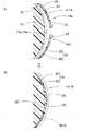
【課題】ヒータエレメントの周囲に表皮層が設けられても、感触の低下を抑制できるステアリングホイールを提供すること。【解決手段】操舵中心軸を中心として回転操作可能な環状の把持部が、芯材を被覆する被覆層と外表面側の表皮層との間に、操舵中心軸回りの周方向に沿う帯状のシート体からなるヒータエレメント14、を配設させて構成されるステアリングホイール。ヒータエレメントは、可撓性を有したシート状とした被覆層側の裏側基材20と表皮層側の表側基材23とを、ヒータ線35を間にして相互に接着させて、形成されるとともに、被覆層の外周面側に貼着されて配設される。ヒータエレメントのシート体16は、短手方向WDの両縁16c,16dを、裏側基材20若しくは表側基材23の一方の単層部25として、形成されている。【選択図】図3An object of the present invention is to provide a steering wheel capable of suppressing deterioration in feel even when a skin layer is provided around a heater element. A ring-shaped grip portion that can be rotated around a steering center axis is provided in a belt-like shape along a circumferential direction around the steering center axis between a coating layer covering a core material and a skin layer on the outer surface side. A steering wheel configured by arranging a heater element 14 made of a sheet body. The heater element is formed by bonding a flexible sheet-like back substrate 20 on the coating layer side and a front substrate 23 on the skin layer side to each other with the heater wire 35 interposed therebetween. In addition, it is attached and arranged on the outer peripheral surface side of the coating layer. The sheet body 16 of the heater element is formed with both edges 16 c and 16 d in the width direction WD as one single layer portion 25 of the back side base material 20 or the front side base material 23 . [Selection drawing] Fig. 3
Description
本発明は、運転者が操舵時に把持する環状の把持部に、把持部を昇温可能なヒータエレメントを設けて構成されるステアリングホイールに関する。
BACKGROUND OF THE
従来、この種のステアリングホイールでは、操舵中心軸を中心として回転操作可能な環状の把持部を備え、把持部は、芯材を被覆する被覆層と外表面側の表皮層との間に、操舵中心軸回りの周方向に沿う帯状のシート体からなるヒータエレメント、を配設させて構成されていた(例えば、特許文献1参照)。ヒータエレメントは、可撓性を有したシート状とした被覆層側の裏側基材と表皮層側の表側基材とを、ヒータ線を間にして相互に接着させて、形成されるとともに、被覆層の外周面側に貼着されて配設される構成としていた。 Conventionally, this type of steering wheel has an annular grip portion that can be rotated around a steering center axis. A heater element made of a strip-shaped sheet body along the circumferential direction around the central axis is arranged (see, for example, Patent Document 1). The heater element is formed by bonding a flexible sheet-like back substrate on the coating layer side and a front substrate on the skin layer side to each other with a heater wire interposed therebetween. It was configured to be attached and arranged on the outer peripheral surface side of the layer.
しかし、従来のステアリングホイールにおいて、ヒータエレメントを構成する帯状のシート体が、伸び難ければ、被覆層の表面側に貼着し難く、把持部における操舵中心軸側となる内周側に、シワが発生する等して、表皮層の感触を悪くする事態を招いてしまう。 However, in the conventional steering wheel, if the belt-shaped sheet body constituting the heater element is difficult to stretch, it is difficult to adhere to the surface side of the coating layer, and wrinkles are formed on the inner peripheral side of the grip portion, which is the steering center axis side. , etc., resulting in a situation in which the touch of the epidermis layer is deteriorated.
本発明は、上述の課題を解決するものであり、ヒータエレメントの周囲に表皮層が設けられても、感触の低下を抑制できるステアリングホイールを提供することを目的とする。 SUMMARY OF THE INVENTION It is an object of the present invention to solve the above-described problems and to provide a steering wheel capable of suppressing deterioration in feel even when a skin layer is provided around the heater element.
本発明に係るステアリングホイールでは、操舵中心軸を中心として回転操作可能な環状の把持部を備え、
該把持部が、芯材を被覆する被覆層と外表面側の表皮層との間に、前記操舵中心軸回りの周方向に沿う帯状のシート体からなるヒータエレメント、を配設させて構成され、
前記ヒータエレメントが、可撓性を有したシート状とした前記被覆層側の裏側基材と前記表皮層側の表側基材とを、ヒータ線を間にして相互に接着させて、形成されるとともに、前記被覆層の外周面側に貼着されて配設される構成のステアリングホイールであって、
前記ヒータエレメントの前記シート体が、短手方向の両縁を、前記裏側基材若しくは前記表側基材の一方の単層として、形成されていることを特徴とする。
The steering wheel according to the present invention includes an annular grip that can be rotated around the steering center axis,
The grip portion is configured by disposing a heater element made of a belt-shaped sheet body along the circumferential direction around the steering center axis between a coating layer that covers the core material and a skin layer on the outer surface side. ,
The heater element is formed by bonding a flexible sheet-like back base material on the cover layer side and a front side base material on the skin layer side to each other with a heater wire interposed therebetween. and a steering wheel that is attached and disposed on the outer peripheral surface side of the coating layer,
The sheet body of the heater element is characterized in that both edges in the width direction are formed as a single layer of either the back side base material or the front side base material.
本発明に係るステアリングホイールでは、ヒータエレメントの帯状のシート体を、被覆層の外周面側に貼着させるように、短手方向に伸ばす際、短手方向の両縁が、被覆層側の裏側基材と表皮層側の表側基材との2層を配設させておらず、一方側の単層から構成されており、相互に接着された裏側基材と表側基材との2層構造でないことから、容易に、短手方向に伸ばすことができて、把持部における操舵中心軸側となる内周側にシワを生じさせずに、ヒータエレメントを被覆層の外周面側に貼着させることができる。そのため、その後に表皮層を配設させても、シワ無く、円滑に、表皮層が配設される。 In the steering wheel according to the present invention, when the strip-shaped sheet body of the heater element is stretched in the transverse direction so as to be attached to the outer peripheral surface side of the coating layer, both edges in the transverse direction are aligned with the back side of the coating layer side. The two layers of the base material and the front side base material on the skin layer side are not arranged, and it is composed of a single layer on one side, and has a two-layer structure of the back side base material and the front side base material that are adhered to each other. Therefore, the heater element can be easily stretched in the lateral direction, and the heater element can be adhered to the outer peripheral surface side of the coating layer without causing wrinkles on the inner peripheral side, which is the steering center axis side, of the grip part. be able to. Therefore, even if the skin layer is disposed after that, the skin layer is smoothly disposed without wrinkles.
したがって、本発明に係るステアリングホイールでは、ヒータエレメントの周囲に表皮層が設けられても、ヒータエレメントにシワが生じ難いことから、シワ無く配設できて、感触の低下を抑制できる。 Therefore, in the steering wheel according to the present invention, even if the skin layer is provided around the heater element, the heater element is less likely to wrinkle.
そして、本発明に係るステアリングホイールでは、前記ヒータエレメントの前記シート体における短手方向の両縁が、それぞれ、前記表側基材の単層として、形成されていることが望ましい。 Further, in the steering wheel according to the present invention, it is preferable that both lateral edges of the sheet body of the heater element are each formed as a single layer of the front base material.
このような構成では、表皮層に近い側の表側基材が、短手方向の全域を構成することから、被覆層に貼着させたヒータエレメントの外表面側を、段差を抑制した面一状とすることができて、その後に表皮層を配設させる際、一層、シワ無く、表皮層を配設させることができる。 In such a configuration, since the front base material on the side closer to the skin layer constitutes the entire widthwise direction, the outer surface side of the heater element adhered to the coating layer is flattened to suppress steps. As a result, when the skin layer is disposed thereafter, the skin layer can be disposed without further wrinkles.
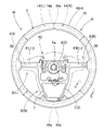
以下、本発明の一実施形態を図面に基づいて説明すると、実施形態のステアリングホイールWは、図1に示すように、操舵時に操舵中心軸COを中心として回転操舵可能な略円環状の把持部Rと、把持部Rの略中央に位置する操舵中心軸CO側のボス部Bと、把持部Rとボス部Bとを連結するスポーク部S(L,R,B)と、を備えて構成されている。スポーク部Sは、ボス部Bから左右両側に延びるスポーク部SL,SRと、ボス部Bから後側に延びるスポーク部SBと、を備えている。また、ステアリングホイールWは、ボス部Bの上部側に配設される二点鎖線で示したエアバッグ装置45と、ステアリングホイール本体1と、ボス部Bの下部側を覆う図示しないロアカバーと、を備えて構成されている。
An embodiment of the present invention will be described below with reference to the drawings. As shown in FIG. 1, the steering wheel W of the embodiment has a substantially annular grip portion that can be rotatably steered around the steering center axis CO during steering. R, a boss portion B on the side of the steering center axis CO located substantially in the center of the grip portion R, and spoke portions S (L, R, B) connecting the grip portion R and the boss portion B. It is The spoke portion S includes spoke portions SL and SR extending from the boss portion B to the left and right sides, and spoke portions SB extending from the boss portion B to the rear side. Further, the steering wheel W includes an
さらに、ステアリングホイール本体1は、把持部R、ボス部B、及び、スポーク部Sを連結するアルミニウム合金等の金属材からなる芯材3、を備えて構成されている。芯材3は、把持部Rに配設される把持芯材部4と、ボス部Bに配設されるボス芯材部5と、把持芯材部4とボス芯材部5とを連結するように、スポーク部S(L,R,B)に配設されるスポーク芯材部6(L,R),7と、を備えて構成されている。ボス芯材部5は、操舵中心軸COを形成する車両の図示しないステアリングシャフトと結合される鋼製のボス5aを配設させている。また、スポーク芯材部6は、左右のスポーク部SL,SRに配設されるスポーク芯材部6L,6Rと、後部側のスポーク部SBに配設されて、ボス芯材部5側で左右に分岐し、そして、把持芯材部4側で結合されるような2本のスポーク芯材部7,7と、から構成されている。
Further, the
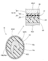
把持部Rに配設される把持芯材部4の周囲には、図2に示すように、発泡ポリウレタンからなる被覆層10が配設されるとともに、把持部Rの表面側に、皮革41からなる表皮層40が配設され、さらに、被覆層10と表皮層40との間には、把持部Rを昇温可能なヒータエレメント14が配設されている。
As shown in FIG. 2, a
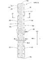
ヒータエレメント14は、図3,4に示すように、可撓性を有したシート状の基材19にヒータ線35を保持させて、形成されるもので、把持部Rにおける操舵中心軸CO回りの周方向に沿う帯状のシート体16から構成されている。実施形態の場合、ヒータエレメント14は、把持部Rの左右の片側ずつに配設され、ステアリングホイールW全体では、2枚、使用される。実施形態の場合、図1に示す右方側のヒータエレメント14Rと左方側のヒータエレメント14Lとは、左右対称形としている点が異なるだけであることから、図3に示す右方側のヒータエレメント14(R)について説明して、左方側のヒータエレメント14(L)については説明を省略する。
As shown in FIGS. 3 and 4, the
そして、ヒータエレメント14を形成するシート体16の基材19は、被覆層10側の裏側基材20と表皮層40側の表側基材23との2層から構成されるとともに、裏側基材20と表側基材23とは、ヒータ線35を間にして相互に接着されることにより、ヒータ線35を挟持するように保持する構成としている(図4参照)。
The
また、実施形態のシート体16では、短手方向WDの両縁(側縁)16c,16dが、裏側基材20若しくは表側基材23の一方の単層として、形成されている。実施形態の場合、側縁16c,16dは、表側基材23の単層とした単層部25から形成されている。実施形態の場合、シート体16(ヒータエレメント14)の幅寸法WL0が90~110mm程度の範囲内の100mmとしており、単層部25の幅寸法WL1は、5~25mm程度の範囲内の12mmとしている。換言すれば、単層部25の幅寸法WL1は、シート体16(ヒータエレメント14)の幅寸法WL0の4~27%程度としている。
In addition, in the
さらに、裏側基材20と表側基材23とは、共に、発泡ポリウレタンのシート材から形成されて、裏側基材20と表側基材23の厚さ寸法tA1,tB1は、共に、0.5~0.8mmの範囲内の0.7mmとしている。但し、裏側基材20と表側基材23との密度に関しては、表側基材23側の密度が、裏側基材20の密度より、高くされている。具体的には、裏側基材20の密度は、0.1~0.3g/cm3程度の範囲内の0.2g/cm3としている。表側基材23の密度は、0.3~0.7g/cm3程度の範囲内の0.5g/cm3としている。ちなみに、実施形態では、ヒータエレメント14における表皮層40に近い側の表側基材23が、密度を高くして、熱伝導率を良好にできることから、ヒータ線35の発熱時の熱を表皮層40側に伝導させ易くなり、逆に、裏側基材20が、密度を低くして、断熱性を向上させることとなり、芯材3(把持芯材部4)側への熱伝導を抑制して、通電時の表皮層40側での昇温を効率的に行える。
Further, the back
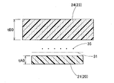
また、実施形態の場合、図5に示すように、裏側基材20は、厚さ寸法tA0を3~4mm程度の3.5mmとしていたシート状の予備裏側部材21を、1/5程度の厚さ寸法tA1の0.7mm、とするように圧縮し、表側基材23は、厚さ寸法tB0を5~10mm程度の8mmとしていたシート状の予備表側部材24を、1/12程度の厚さ寸法tB1の0.7mmとするように圧縮して、形成されている。
Further, in the case of the embodiment, as shown in FIG. 5, the back
そして、ヒータエレメント14は、同等の厚さ寸法tA1,tB1とした裏側基材20と表側基材23とを、所定配線パターンとした状態のヒータ線35を間にして、粘着剤31を利用して、相互に接着させることにより、形成されている。
The
なお、ヒータ線35は、実施形態の場合、外径約0.2mm程度の芳香族ポリアミド繊維束からなるヒータ芯の外周に、素線径0.08mm程度の錫銅合金線からなる導体素線を複数本(7本程度)、引き揃え、ピッチ1.00mm程度で螺旋状に巻装して構成されている。実施形態のヒータ線35は、その線径を0.37mm程度としている。そして、ヒータ線35は、図3に示すように、一筆書き状の所定のパターンで、基材19の裏側基材20と表側基材23の間に保持されて、図示しない温度制御装置に接続されるリード線36に結線されている。
In the case of the embodiment, the
また、製造したヒータエレメント14は、幅方向(短手方向)WDの側縁16c,16d側が、被覆層10に巻き付ける際、把持部Rの内周面側に配置されて、シワを発生し易いことから、予め、側縁16c,16d側に、三角形状の切欠き17を設けておく(図3参照)。
Further, in the manufactured
実施形態のステアリングホイールWの製造では、ステアリングホイール本体1における芯金2の把持芯材部4と把持芯材部4近傍のスポーク芯材部6,7との周囲に、被覆層10を設けた後、被覆層10の外周面10a側にヒータエレメント14を貼着させる。その際、左右のヒータエレメント14の端縁16a,16b相互を付き合わせるように、引っ張りつつ、ヒータエレメント14の側縁16c,16d側を、図6に示すように、引っ張りつつ、被覆層10の外周面10a側に貼着させる。その際、側縁16c,16dが、裏側基材20と表側基材23とを接着させた2層構造でなく、表側基材23だけの単層部25としていることから、伸び易く、把持部Rの内周面側における被覆層10の外周面10aにおける内側面10c側に、シワを生じさせずに、貼着することができる。勿論、側縁16c,16d側には、切欠き17も配設されており、側縁16c,16d側は、外周面10aへの貼着時、切欠き17を狭める状態として、一層、シワを生じさせずに、把持部Rの内周面側における被覆層10の外周面10aに、貼着することができる。なお、被覆層10の外周面10aの外側面10b側では、左右のヒータエレメント14の端縁16a,16b相互を付き合わせるように、引っ張りつつ、貼着させる。
In the production of the steering wheel W of the embodiment, the covering
ヒータエレメント14を貼着した後には、ヒータエレメント14の外周面側に、粘着剤38を利用して、表皮層40として皮革41を巻き付ければ、ステアリングホイール本体1を製造できる。その後は、ボス部Bの下部側に図示しないロアカバーを取り付けつつ、ボス部Bのボス5aを、車両のステアリングシャフトに締結し、ボス部Bの上部側に、エアバッグ装置45を取り付ければ、ステアリングホイールWを組み立てることができるとともに、ステアリングホイールWを車両に搭載することができる。なお、エアバッグ装置45を取り付ける際には、ヒータエレメント14のリード線36を、運転者の把持を検知可能な図示しない検知回路から伸びるリード線に結線させておく。
After attaching the
車両に搭載されたステアリングホイールWでは、図示しない温度制御装置の制御により、ヒータエレメント14のヒータ線35に通電されて、把持部Rが所定温度に昇温されることとなる。
In the steering wheel W mounted on the vehicle, the
そして、実施形態のステアリングホイールWでは、ヒータエレメント14の帯状のシート体16を、被覆層10の外周面10a側に貼着させるように、短手方向WDに伸ばす際、短手方向WDの両縁16c,16dが、被覆層10側の裏側基材20と表皮層40側の表側基材23との2層を配設させておらず、一方側の単層部25から構成されており、相互に接着された裏側基材20と表側基材23との2層構造でないことから、容易に、短手方向WDに伸ばすことができて、把持部Rにおける操舵中心軸CO側となる内周側(内側面10c側)にシワを生じさせずに、ヒータエレメント14を被覆層10の外周面10a側に貼着させることができる。そのため、その後に表皮層40を配設させても、シワ無く、円滑に、表皮層40が配設される。
In the steering wheel W of the embodiment, when the strip-shaped
したがって、実施形態のステアリングホイールWでは、ヒータエレメント14の周囲に表皮層40が設けられても、ヒータエレメント14にシワが生じ難いことから、シワ無く配設できて、感触の低下を抑制できる。
Therefore, in the steering wheel W of the embodiment, even if the skin layer 40 is provided around the
そして、実施形態のステアリングホイールWでは、ヒータエレメント14のシート体16における短手方向WDの両縁16c,16dが、それぞれ、表側基材23の単層部25として、形成されている。
In the steering wheel W of the embodiment, both
そのため、実施形態では、表皮層40に近い側の表側基材23が、短手方向WDの全域を構成することから、被覆層10に貼着させたヒータエレメント14の外表面側を、段差を抑制した面一状とすることができて、その後に表皮層40を配設させる際、一層、シワ無く、表皮層40を配設させることができる。
Therefore, in the embodiment, since the
勿論、図7に示すヒータエレメント14Aのシート体16Aのように、短手方向WDの両縁16c,16dを、裏側基材20A側の単層部25Aから、構成してもよい。すなわち、ヒータ線35を挟持するように保持する基材19Aとして裏側基材20Aと表側基材23Aとにおいて、短手方向WDの両縁16c,16dが、裏側基材20Aだけで構成されている。なお、これらの裏側基材20Aと表側基材23Aとは、実施形態の裏側基材20や表側基材23と同じ発泡ポリウレタンから形成されている。
Of course, like the
この場合のシート体16Aでも、被覆層10の外周面10a側に貼着させるように、短手方向WDに伸ばす際、短手方向WDの両縁16c,16dが、被覆層10側の裏側基材20Aと表皮層40側の表側基材23Aとの2層を配設させておらず、一方側の単層部25Aから構成されており、相互に接着された裏側基材20Aと表側基材23Aとの2層構造でないことから、容易に、短手方向WDに伸ばすことができて、把持部Rにおける操舵中心軸CO側となる内周側(内側面10c側)にシワを生じさせずに、ヒータエレメント14Aを被覆層10の外周面10a側に貼着させることができる。そのため、その後に表皮層40を配設させても、シワ無く、円滑に、表皮層40が配設される。
Even in this case, the
なお、ヒータエレメントの長手方向LDにも伸びやすいように構成する場合には、例えば、図8~10に示すように、表側基材23Bに、短手方向WDに沿って形成され、かつ、長手方向LDに並設されるように、多数のスリット26を形成したヒータエレメント14Bを使用してもよい。スリット26は、表側基材23Bの表皮層40側となる表面側に形成されている。
In the case where the heater element is configured to easily extend in the longitudinal direction LD, for example, as shown in FIGS. A
このヒータエレメント14Bでは、ヒータ線35を挟持するように保持する基材19Bとして裏側基材20Bと表側基材23Bとにおいて、短手方向WDの両縁16c,16dが、表側基材23Bだけで構成されている。なお、これらの裏側基材20Bと表側基材23Bとは、実施形態の裏側基材20や表側基材23と同じ発泡ポリウレタンから形成されている。
In this
このヒータエレメント14Bでは、被覆層10の外表面10aに貼着させる際、シート体16Bにおける短手方向WDの両縁16c,16dが単層部25Bから構成されており、内側面10c側(図6参照)にシワ無く、貼り付けることができる。そしてさらに、ヒータエレメント14Bの帯状のシート体16Bを、被覆層10の外周面10a側に貼着させるように、長手方向LDに伸ばす際、外周面10aの外側面10b側では、図10に示すように、各スリット26がスリット26内の対向壁26b,26b相互を広げるように開口して、容易に、長手方向LDに伸びて、シワを生じさせずに、被覆層10の外周面10a側に貼着させることができる。そのため、その後に表皮層40を配設させても、シワ無く、円滑に、表皮層40が配設されることとなる。
In this
ちなみに、上記のようなスリット26は、発泡ポリウレタン製の裏側基材20Bと表側基材23Bとが相互に接着された2層構造としたヒータエレメント14Bであって、長手方向LDの伸びが抑制されている場合に、好適となる。
Incidentally, the
なお、表側基材23Bにスリットを設ける場合、表面側のスリット26だけでなく、裏面側にもスリットを配設してもよい。
When slits are provided in the front
3…芯材、4…把持芯材部、10…被覆層、10a…外周面、14,14A,14B…ヒータエレメント、16,16A,16B…シート体、16a…側縁、
16b…側縁、20,20A,20B…裏側基材、23,23A,23B…表側基材、25,25A,25B…単層部、35…ヒータ線、40…表皮層、
WD…(シート体の)短手方向、LD…(シート体の)長手方向、R…把持部、CO…操舵中心軸、W…ステアリングホイール。
3...
16b... side edge, 20, 20A, 20B... back side base material, 23, 23A, 23B... front side base material, 25, 25A, 25B... single layer portion, 35... heater wire, 40... skin layer,
WD... Width direction (seat body), LD... Longitudinal direction (seat body), R... Grip portion, CO... Steering central axis, W... Steering wheel.
Claims (2)
該把持部が、芯材を被覆する被覆層と外表面側の表皮層との間に、前記操舵中心軸回りの周方向に沿う帯状のシート体からなるヒータエレメント、を配設させて構成され、
前記ヒータエレメントが、可撓性を有したシート状とした前記被覆層側の裏側基材と前記表皮層側の表側基材とを、ヒータ線を間にして相互に接着させて、形成されるとともに、前記被覆層の外周面側に貼着されて配設される構成のステアリングホイールであって、
前記ヒータエレメントの前記シート体が、短手方向の両縁を、前記裏側基材若しくは前記表側基材の一方の単層として、形成されていることを特徴とするステアリングホイール。 Equipped with an annular grip that can be rotated around the steering center axis,
The grip portion is configured by disposing a heater element made of a belt-shaped sheet body along the circumferential direction around the steering center axis between a coating layer that covers the core material and a skin layer on the outer surface side. ,
The heater element is formed by bonding a flexible sheet-like back base material on the cover layer side and a front side base material on the skin layer side to each other with a heater wire interposed therebetween. and a steering wheel that is attached and disposed on the outer peripheral surface side of the coating layer,
A steering wheel according to claim 1, wherein the sheet body of the heater element is formed of a single layer of either the back side base material or the front side base material on both lateral edges.
Priority Applications (1)
| Application Number | Priority Date | Filing Date | Title |
|---|---|---|---|
| JP2021083475A JP7392685B2 (en) | 2021-05-17 | 2021-05-17 | steering wheel |
Applications Claiming Priority (1)
| Application Number | Priority Date | Filing Date | Title |
|---|---|---|---|
| JP2021083475A JP7392685B2 (en) | 2021-05-17 | 2021-05-17 | steering wheel |
Publications (2)
| Publication Number | Publication Date |
|---|---|
| JP2022176830A true JP2022176830A (en) | 2022-11-30 |
| JP7392685B2 JP7392685B2 (en) | 2023-12-06 |
Family
ID=84234226
Family Applications (1)
| Application Number | Title | Priority Date | Filing Date |
|---|---|---|---|
| JP2021083475A Active JP7392685B2 (en) | 2021-05-17 | 2021-05-17 | steering wheel |
Country Status (1)
| Country | Link |
|---|---|
| JP (1) | JP7392685B2 (en) |
Cited By (1)
| Publication number | Priority date | Publication date | Assignee | Title |
|---|---|---|---|---|
| CN117885799A (en) * | 2024-01-23 | 2024-04-16 | 均胜均安汽车电子(上海)有限公司 | Hands-off detection steering wheel and vehicle |
Citations (4)
| Publication number | Priority date | Publication date | Assignee | Title |
|---|---|---|---|---|
| JPH10507990A (en) * | 1995-08-24 | 1998-08-04 | リヴァーウッド インターナショナル コーポレーション | Open-top container with laminated end panels |
| JP2015027840A (en) * | 2013-07-30 | 2015-02-12 | 日本プラスト株式会社 | Steering wheel |
| JP2016006750A (en) * | 2014-06-20 | 2016-01-14 | 豊田合成株式会社 | Heater element and steering wheel |
| JP2016016790A (en) * | 2014-07-09 | 2016-02-01 | 日本プラスト株式会社 | handle |
-
2021
- 2021-05-17 JP JP2021083475A patent/JP7392685B2/en active Active
Patent Citations (4)
| Publication number | Priority date | Publication date | Assignee | Title |
|---|---|---|---|---|
| JPH10507990A (en) * | 1995-08-24 | 1998-08-04 | リヴァーウッド インターナショナル コーポレーション | Open-top container with laminated end panels |
| JP2015027840A (en) * | 2013-07-30 | 2015-02-12 | 日本プラスト株式会社 | Steering wheel |
| JP2016006750A (en) * | 2014-06-20 | 2016-01-14 | 豊田合成株式会社 | Heater element and steering wheel |
| JP2016016790A (en) * | 2014-07-09 | 2016-02-01 | 日本プラスト株式会社 | handle |
Cited By (1)
| Publication number | Priority date | Publication date | Assignee | Title |
|---|---|---|---|---|
| CN117885799A (en) * | 2024-01-23 | 2024-04-16 | 均胜均安汽车电子(上海)有限公司 | Hands-off detection steering wheel and vehicle |
Also Published As
| Publication number | Publication date |
|---|---|
| JP7392685B2 (en) | 2023-12-06 |
Similar Documents
| Publication | Publication Date | Title |
|---|---|---|
| US11390312B2 (en) | Steering wheel | |
| US10597060B2 (en) | Steering wheel and method of manufacturing same | |
| EP1199241B1 (en) | Heater, heater-equipped steering wheel, and method of manufacturing such steering wheel | |
| JP2022152440A (en) | Coating member and steering wheel | |
| US9173249B2 (en) | Steering wheel | |
| JP6937481B2 (en) | Electrode connection structure and electrode connection method | |
| CN110116750B (en) | Covering member for steering wheel, and method for manufacturing steering wheel | |
| JP6642703B2 (en) | Manufacturing method of steering wheel | |
| JP7392685B2 (en) | steering wheel | |
| JP6117046B2 (en) | handle | |
| JP2014151776A (en) | Steering wheel | |
| US20220212711A1 (en) | Heating structure and steering wheel | |
| JP4150477B2 (en) | Steering wheel | |
| JP2024148019A (en) | Electrode Structure | |
| JP6283581B2 (en) | Steering wheel | |
| JP2017159849A (en) | Steering Wheel | |
| JP7461602B2 (en) | Steering Wheel | |
| JP7817808B2 (en) | Detection device, steering wheel, and method of manufacturing the detection device | |
| JP2011073546A (en) | Steering wheel | |
| JP2011207451A (en) | Steering wheel | |
| JPH027101Y2 (en) | ||
| JP2024163610A (en) | Electrode Structure | |
| JP2002096737A (en) | Heater device, steering wheel, and method of manufacturing steering wheel | |
| JP2022095372A (en) | Steering wheel | |
| JP7647646B2 (en) | handle |
Legal Events
| Date | Code | Title | Description |
|---|---|---|---|
| A621 | Written request for application examination |
Free format text: JAPANESE INTERMEDIATE CODE: A621 Effective date: 20230524 |
|
| A977 | Report on retrieval |
Free format text: JAPANESE INTERMEDIATE CODE: A971007 Effective date: 20231005 |
|
| TRDD | Decision of grant or rejection written | ||
| A01 | Written decision to grant a patent or to grant a registration (utility model) |
Free format text: JAPANESE INTERMEDIATE CODE: A01 Effective date: 20231024 |
|
| A61 | First payment of annual fees (during grant procedure) |
Free format text: JAPANESE INTERMEDIATE CODE: A61 Effective date: 20231106 |
|
| R151 | Written notification of patent or utility model registration |
Ref document number: 7392685 Country of ref document: JP Free format text: JAPANESE INTERMEDIATE CODE: R151 |