JP2023007714A - Connection method of shell - Google Patents
Connection method of shell Download PDFInfo
- Publication number
- JP2023007714A JP2023007714A JP2021110737A JP2021110737A JP2023007714A JP 2023007714 A JP2023007714 A JP 2023007714A JP 2021110737 A JP2021110737 A JP 2021110737A JP 2021110737 A JP2021110737 A JP 2021110737A JP 2023007714 A JP2023007714 A JP 2023007714A
- Authority
- JP
- Japan
- Prior art keywords
- tubular body
- sheet
- intermediate tubular
- shell
- concrete
- Prior art date
- Legal status (The legal status is an assumption and is not a legal conclusion. Google has not performed a legal analysis and makes no representation as to the accuracy of the status listed.)
- Pending
Links
- 238000000034 method Methods 0.000 title claims abstract description 41
- 239000004567 concrete Substances 0.000 claims abstract description 77
- 239000000463 material Substances 0.000 claims abstract description 59
- 238000007789 sealing Methods 0.000 claims description 16
- UQMRAFJOBWOFNS-UHFFFAOYSA-N butyl 2-(2,4-dichlorophenoxy)acetate Chemical compound CCCCOC(=O)COC1=CC=C(Cl)C=C1Cl UQMRAFJOBWOFNS-UHFFFAOYSA-N 0.000 abstract 1
- XLYOFNOQVPJJNP-UHFFFAOYSA-N water Substances O XLYOFNOQVPJJNP-UHFFFAOYSA-N 0.000 description 15
- 229920005989 resin Polymers 0.000 description 9
- 239000011347 resin Substances 0.000 description 9
- 238000010276 construction Methods 0.000 description 8
- 229910000831 Steel Inorganic materials 0.000 description 7
- 239000010959 steel Substances 0.000 description 7
- 239000011440 grout Substances 0.000 description 4
- 238000000465 moulding Methods 0.000 description 3
- 239000004745 nonwoven fabric Substances 0.000 description 3
- -1 polyethylene Polymers 0.000 description 3
- 239000004698 Polyethylene Substances 0.000 description 2
- 238000000605 extraction Methods 0.000 description 2
- 239000000945 filler Substances 0.000 description 2
- 239000012530 fluid Substances 0.000 description 2
- 239000002184 metal Substances 0.000 description 2
- 239000004570 mortar (masonry) Substances 0.000 description 2
- 229920000573 polyethylene Polymers 0.000 description 2
- 239000004743 Polypropylene Substances 0.000 description 1
- BZHJMEDXRYGGRV-UHFFFAOYSA-N Vinyl chloride Chemical compound ClC=C BZHJMEDXRYGGRV-UHFFFAOYSA-N 0.000 description 1
- 239000004568 cement Substances 0.000 description 1
- 239000000470 constituent Substances 0.000 description 1
- 230000003247 decreasing effect Effects 0.000 description 1
- 238000010438 heat treatment Methods 0.000 description 1
- 230000010354 integration Effects 0.000 description 1
- 239000012466 permeate Substances 0.000 description 1
- 229920005672 polyolefin resin Polymers 0.000 description 1
- 229920001155 polypropylene Polymers 0.000 description 1
- 239000011178 precast concrete Substances 0.000 description 1
- 239000005060 rubber Substances 0.000 description 1
- 239000003566 sealing material Substances 0.000 description 1
- 239000004636 vulcanized rubber Substances 0.000 description 1
Images


Landscapes
- Bridges Or Land Bridges (AREA)
Abstract
Description
この発明は、コンクリート部材に埋設される管体の接続方法に関するものである。 The present invention relates to a method for connecting pipes embedded in concrete members.
従来から、工場や専用のヤード等において予めコンクリート部材を製作し、そのコンクリート部材を現場に運搬して一体化する工法がある。この工法はプレキャスト工法と呼ばれ、各種建築物をはじめ、橋梁の橋桁、床版、壁高欄、地下構造物、その他各種土木構造物にも用いられている。このプレキャスト工法によって構築された構造をプレキャスト構造という。 Conventionally, there is a construction method in which concrete members are manufactured in advance in a factory, a dedicated yard, or the like, and the concrete members are transported to the site and integrated. This construction method is called a precast construction method, and is used not only for various buildings but also for bridge girders, floor slabs, wall balustrades, underground structures, and various other civil engineering structures. A structure constructed by this precast construction method is called a precast structure.
ところで、コンクリート部材の内部に管体が埋め込み固定される場合がある。例えば、高速道路や高架構造物等において、コンクリート壁高欄等を構成するコンクリート部材の内部に、ケーブル等を収納する管体、あるいは、流体を輸送するための管体等が埋設される場合がある。また、例えば、プレキャスト工法で用いられるコンクリート部材の内部には、PC鋼材挿通用の管体が埋設される。 By the way, there are cases where a tubular body is embedded and fixed inside a concrete member. For example, in expressways and elevated structures, there are cases where pipes for storing cables or the like or pipes for transporting fluids are buried inside concrete members that make up concrete wall balustrades. . Further, for example, a tubular body for inserting a PC steel material is embedded inside a concrete member used in the precast construction method.
隣り合うコンクリート部材間での管体同士の接続は、一方のコンクリート部材の管体と他方のコンクリート部材の管体とが、接続用の中間管体によって接続されているものが一般的である。例えば、特許文献1では、接続用の中間管体(PC鋼材保護用管体接続管)に対して、コンクリート部材の管体との間で止水するシール部材を貼りつけたものが知られている。
As for the connection of tubular bodies between adjacent concrete members, it is common to connect the tubular bodies of one concrete member and the tubular bodies of the other concrete member by an intermediate tubular body for connection. For example, in
この特許文献1に示す中間管体のシール部材は、水膨張性を有する不織布が採用されており、このシール部材によって隣り合うコンクリート部材間にコンクリートを打設する際に、コンクリート部材の管体内への水の侵入を防止している。
The sealing member of the intermediate pipe shown in this
しかしながら、雨や雪が降る天候においては、特許文献1に示す中間管体を隣り合うコンクリート部材間の管体に接続する際、その中間管体のシール部材が雨水などで膨潤する恐れがある。シール部材が膨潤している中間管体では、隣り合うコンクリート部材間の管体を接続することができない場合があり得る。
However, in rainy or snowy weather, when connecting the intermediate tubular body shown in
そこで、この発明の課題は、管体が埋設されたコンクリート部材を用いるプレキャスト工法において、雨や雪の降る天候であってもコンクリート部材間の管体を接続できるようにすることである。 SUMMARY OF THE INVENTION Accordingly, an object of the present invention is to enable a pipe between concrete members to be connected even in rainy or snowy weather in a precast construction method using concrete members in which pipes are embedded.
上記の課題を解決するために、この発明は、第一のコンクリート部材に埋設される筒状の第一管体と、第二のコンクリート部材に埋設される筒状の第二管体とを、前記第一管体の内面部と前記第二管体の内面部とにそれぞれ摺接するシール部材を備えた筒状の中間管体で接続する管体の接続方法において、前記中間管体を防水性を有するシート状物で覆う第1工程と、前記シート状物で覆った前記中間管体を前記第一管体または第二管体の一方に差し込む第2工程と、前記中間管体から前記シート状物を除去する第3工程と、前記中間管体を前記第一管体または第二管体の他方に差し込む第4工程とを含む管体の接続方法を採用することができる。 In order to solve the above-mentioned problems, the present invention comprises a tubular first tubular body embedded in a first concrete member and a tubular second tubular body embedded in a second concrete member, In the method for connecting tubular bodies by means of a tubular intermediate tubular body provided with a sealing member that is in sliding contact with the inner surface portion of the first tubular body and the inner surface portion of the second tubular body, the intermediate tubular body is waterproof. and a second step of inserting the intermediate tubular body covered with the sheet-shaped article into either the first tubular body or the second tubular body, and from the intermediate tubular body to the sheet It is possible to adopt a method of connecting tubular bodies, which includes a third step of removing an object, and a fourth step of inserting the intermediate tubular body into the other of the first tubular body or the second tubular body.
この接続方法によると、中間管体に対して、雨や雪などの水がかかることを防ぐ必要がある箇所を、防水性を有するシート状物で覆うことができる。また、中間管体を第一管体の内部と第二管体の内部とに差し込んだ後に、シート状物を第一のコンクリート部材および第二のコンクリート部材との間から抜き取るので、中間管体のシール部材に水がかかることを防ぐことができる。 According to this connection method, it is possible to cover a portion of the intermediate tubular body that needs to be protected from water such as rain or snow with a waterproof sheet-like material. Further, after inserting the intermediate tubular body into the inside of the first tubular body and the inside of the second tubular body, the sheet-like material is pulled out from between the first concrete member and the second concrete member. It is possible to prevent water from splashing on the sealing member.
また、前記第3工程は、前記中間管体から前記シート状物の前記一方側の端部を離脱させる一方側除去工程と、前記中間管体から前記シート状物の前記他方側の端部を離脱させる他方側除去工程と、を含み、前記一方側除去工程は、前記中間管体を前記一方に接近させ、前記一方の内部に差し込んだ後に行う、管体の接続方法を採用することができる。 The third step includes a one-side removal step of removing the one-side end of the sheet-like object from the intermediate tubular body, and a one-side removing step of removing the other-side end of the sheet-like object from the intermediate tubular body. and the other side removing step of detaching, wherein the one side removing step can adopt a tubular body connection method performed after the intermediate tubular body is brought close to the one and inserted into the inside of the one. .
この管体の接続方法では、中間管体を前記一方の内部に差し込み、中間管体からシート状物の前記一方側を剥がすので、前記一方側に差し込まれる中間管体のシール部材に水がかかり難くなる。 In this method of connecting tubular bodies, the intermediate tubular body is inserted into the inside of the one, and the one side of the sheet-like material is peeled off from the intermediate tubular body. it gets harder.
上記管体の接続方法において、前記第3工程は、前記中間管体から前記シート状物の前記一方側の端部を離脱させる一方側除去工程と、前記中間管体から前記シート状物の前記他方側の端部を離脱させる他方側除去工程とを含み、前記一方側除去工程は、前記中間管体を前記一方に接近させた後、前記一方の内部に差し込む前に行う、管体の接続方法を採用することができる。 In the method for connecting tubular bodies, the third step includes a one-side removing step of removing the one-side end of the sheet-like object from the intermediate tubular body, and a one-side removing step of removing the sheet-like object from the intermediate tubular body. and the other side removing step of removing the other end, wherein the one side removing step is performed after bringing the intermediate pipe closer to the one and before inserting it into the one. method can be adopted.
この接続方法によると、中間管体からシート状物の前記一方側の端部を離脱させた後、中間管体を前記一方の内部に差し込むので、中間管体を前記一方の内部に差し込み易くなる。 According to this connection method, the intermediate tubular body is inserted into the one interior after the one-side end of the sheet-like material is detached from the intermediate tubular body, so that the intermediate tubular body can be easily inserted into the one interior. .
さらに、前記第1工程は、前記中間管体の前記一方側の端部の内部に、前記シート状物の端部の第一余剰部を押し込む一方側端処理工程を含む管体の接続方法を採用することができる。この場合、シート状物の第一余剰部で、中間管体の前記一方側に設けられるシール部材を覆う状態に維持することができる。 Further, the first step includes a one-side end processing step of pushing a first surplus portion of the end portion of the sheet-like material into the inside of the one-side end portion of the intermediate pipe body. can be adopted. In this case, the sealing member provided on the one side of the intermediate tubular body can be kept covered with the first surplus portion of the sheet-like article.
また、前記第1工程は、前記シート状物の端部の第二余剰部を前記中間管体の前記他方側の端部で捩って閉じる他方側端処理工程を含むものであってもよい。この場合、シート状物の第二余剰部で、中間管体の前記他方側に設けられるシール部材を覆う状態に維持することができる。 Further, the first step may include a second side end processing step to close the second surplus portion of the end portion of the sheet-like material by twisting it with the other side end portion of the intermediate tubular body. good. In this case, the sealing member provided on the other side of the intermediate tubular body can be kept covered with the second surplus portion of the sheet-like article.
前記第3工程は、前記シート状物の前記他方側の端部を引っ張り、前記シート状物を前記中間管体から完全に離脱させる引き抜き除去工程を含み、前記引き抜き除去工程は、前記中間管体を前記他方に接近させた後に行う、管体の接続方法を採用することができる。この場合、シート状物の前記他方側の端部を引っ張り、第一のコンクリート部材と第二のコンクリート部材との間からシート状物を容易に抜き取ることができる。 The third step includes a pulling-out removing step of pulling the other end of the sheet-like object to completely detach the sheet-like object from the intermediate tubular body. It is possible to adopt a method of connecting the tubular bodies after bringing the two closer to the other. In this case, by pulling the other end of the sheet, the sheet can be easily pulled out from between the first concrete member and the second concrete member.
また、前記第2工程は、前記中間管体で前記一方と前記他方との接続を行う作業現場とは別の場所で行う管体の接続方法を採用することができる。この場合、予め、第2工程を前記作業現場とは別の場所である工場または作業ヤードで行うことができ、中間管体を取り付けた第一のコンクリート部材または第二のコンクリート部材を前記作業現場に搬入することができる。 Further, the second step can adopt a method of connecting tubular bodies which is performed at a place different from the work site where the one and the other are connected by the intermediate tubular body. In this case, the second step can be carried out in advance in a factory or a work yard which is a place different from the work site, and the first concrete member or the second concrete member with the intermediate pipe mounted thereon can be installed at the work site. can be brought into
この発明によれば、管体が埋設されたコンクリート部材を用いるプレキャスト工法において、雨や雪の降る天候であっても、中間管体のシール部材に水がかかることを防ぎつつ、コンクリート部材間の管体を接続できるようになる。 According to the present invention, in a precast construction method using a concrete member in which a tubular body is embedded, even in rainy or snowy weather, water is prevented from splashing on the seal member of the intermediate tubular body, and between the concrete members. You will be able to connect pipes.
この発明の実施形態を図面に基づいて説明する。この実施形態に係るプレキャスト工法で使用されるコンクリート部材(プレキャストコンクリート)に埋設される管体同士を接続する管体の接続構造及びその接続方法について説明する。この実施形態の管体の接続構造は、隣接する第一のコンクリート部材1および第二のコンクリート部材2を一体化するために用いられるものである。この実施形態では、隣り合う2つのコンクリート部材を接続するものであるが、並列する3つ以上のコンクリート部材を接続するものであってもよい。
An embodiment of the invention will be described with reference to the drawings. A pipe connection structure and a connection method for connecting pipes embedded in concrete members (precast concrete) used in the precast construction method according to this embodiment will be described. The pipe connection structure of this embodiment is used to integrate the
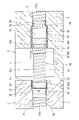
この実施形態の管体の接続方法による管体の接続構造を図1~図6に示す。第一のコンクリート部材1には筒状の第一管体20が埋設されている。また、第二のコンクリート部材2には筒状の第二管体30が埋設されている。また、第一管体20と第二管体30とを接続するために、筒状の中間管体40および中間管体40を覆うシート状物50が用いられる。各管体の素材は、コンクリートcの打ち込みの際に変形しにくく、その継目からセメントペーストが流入しないものが好ましく、例えば、ポリエチレン等の樹脂が多用される。また、各管体には、通常は円形断面の筒状体(チューブ)が用いられる。
FIGS. 1 to 6 show tubular body connection structures according to the tubular body connection method of this embodiment. A tubular first
図1に示すように、第一管体20は、筒軸を通る任意の縦断面で筒軸に平行である第一平坦内面部24と、第一平坦内面部24の奥側の端部に設けられるストッパ部25とを備えている。第一平坦内面部24は、金属製又は硬質樹脂製の筒状部材23の内面で構成されている。筒状部材23は断面円形であり、その内面となる第一平坦内面部24は円筒面である。また、第一管体20は、筒状部材23を外側から保持する断面拡大部22と、その断面拡大部22に接続されて、断面拡大部22の内面よりも小さい断面の内面を有する一般部21を備えている。一般部21も断面円形であるが、その強度を高めるために一般部21の全周に螺旋状のリブ21aが設けられている。一般部21および断面拡大部22は樹脂の成型品である。断面拡大部22は、筒状部材23の圧入によって一般部21よりも外径側へ膨出した形状となっている。ストッパ部25は、断面拡大部22の内面と一般部21の内面との間に設けられた段部で構成されている。断面拡大部22の外面と一般部21の外面との間は、両者を取り付けるテーパ面26となっている。第一管体20は、断面拡大部22の開口側の端縁が、第一のコンクリート部材1の端面(対向面)1aと面一になるように、第一のコンクリート部材1を構成するコンクリートc内に埋設されている。なお、この実施形態では、ストッパ部25を、断面拡大部22の内面と一般部21の内面との間に設けられた段部で構成しているが、これを断面拡大部22の内面と一般部21の内面との間に設けられたテーパ部等としてもよい。
As shown in FIG. 1, the first
また、第二管体30は、筒軸を通る任意の縦断面で筒軸に平行である第二平坦内面部34を備えている。第二平坦内面部34は、金属製又は硬質樹脂製の筒状部材33の内面で構成されている。筒状部材33は断面円形であり、その内面となる第二平坦内面部34は円筒面である。また、第二管体30は、筒状部材33を外側から保持する断面拡大部32と、その断面拡大部32に接続されて、断面拡大部32の内面よりも小断面の内面を有する一般部31とを備えている。一般部31及び断面拡大部32は断面円形であるが、その強度を高めるためにそれぞれの全周に螺旋状のリブ31aが設けられている。一般部31と断面拡大部32は樹脂の成型品である。断面拡大部32は、筒状部材33の圧入によって一般部31よりも外径側へ膨出した形状となっている。第二管体30には、断面拡大部32の内面と一般部31の内面との間にストッパ部38が設けられている。ストッパ部38は、第一管体20の場合と同様に、段部又はテーパ部等で構成することができる(この実施形態ではストッパ部38をテーパ部で構成している)。断面拡大部32の外面と一般部31の外面との間は、両者を取り付けるテーパ面36となっている。第二管体30は、断面拡大部32の開口側の端縁が、第二のコンクリート部材2の端面(対向面)2a側に開口するように、第二のコンクリート部材2を構成するコンクリートc内に埋設されている。なお、上記の断面拡大部22、32における筒状部材23、33の圧入は、樹脂等の構成素材を加熱した後に行うことで容易に可能である。
The second
第二のコンクリート部材2には、第二管体30の開口部付近に、対向面2aに開口する作業用空間(切り欠き空間)3が設けられている。作業用空間3は、対向面2aから第二管体30の奥側へ向かって奥端面3aに至り、上方が開放している。第二管体30の断面拡大部32の開口側の端縁は、第二のコンクリート部材2の作業用空間3の奥端面3aと面一になっている。
The second
中間管体40は、その全長に亘って本体部41を備えている。本体部41は断面円形であり、同じくその強度を高めるために全周に螺旋状のリブ41aが設けられている。また、中間管体40は、その外周にねじ結合されているナット42を備えている。ナット42の内周の雌ねじが、本体部41の外周のリブ41a(雄ねじ)にねじ合っているので、ナット42を筒軸回りに回転させることでナット42は中間管体40に対して筒軸方向へ相対移動する。このナット42は、後述の保持手段60として機能する。本体部41及びナット42は樹脂の成型品である。ナット42は本体部41の外周にねじ合うものであればよく、例えば、ナット42として、第一管体20や第二管体30の一般部21、31の部材を、筒軸方向に対して所定の長さに切断したものを用いることができる。これにより、既存の部材を活用してナット42を製作できるので、コストダウンを図ることができる。
The intermediate
中間管体40の筒軸方向両側の外周に、シール部材43a、43bが設けられている。シール部材43a、43bは、中間管体40が第一管体20及び第二管体30内に挿入された状態で、第一管体20の第一平坦内面部24及び第二管体30の第二平坦内面部34にそれぞれ摺接する。シール部材43a、43bの素材は、管体内に充填されるモルタル等のグラウトが外部に漏れ出ないように、樹脂やゴム、不織布、フェルト等、ある程度の水密性を発揮するものが望ましい。特に、シール部材43a、43bの素材として、水分を含むことによりその体積が膨張する水膨張性能を有している素材(例えば、水膨張性能を有する不織布シール材)を採用すれば、その水密性をさらに高めることができる。
中間管体40を覆うシート状物50は、水が浸透しない防水性を有する柔軟な素材から形成されている。図2(a)、(b)に示すように、シート状物50は、矩形をなし、中間管体40の長さよりも大きい幅寸法と、中間管体40の周長よりも大きい長さ寸法を有している。シート状物50の素材としては、塩化ビニル樹脂、ポリプロピレンやポリエチレンなどのオレフィン系樹脂、加硫ゴムなどを採用することができる。なお、シート状物50は、中間管体40を収納可能な袋状に形成されたものであってもよい。この袋状に形成されたものは、後述する中間管体40の筒軸方向一端側に開口部を有し、その開口部から中間管体40を出し入れできればよい。さらに、シート状物50は、中間管体40を収納可能であって、両端部に開口部を有する筒状に形成されたものでもよい。
The sheet-
次に、この実施形態の管体の接続方法を図面に基づいて説明する。この管体の接続方法は、第一のコンクリート部材1に埋設される第一管体20と、第二のコンクリート部材2に埋設される第二管体30とを中間管体40で接続するための方法である。この管体の接続方法は、中間管体40をシート状物50で覆う第1工程Aと、シート状物50で覆った中間管体40を第一管体20または第二管体30の一方に差し込む第2工程Bと、中間管体40からシート状物50を除去する第3工程Cと、中間管体40を第一管体20または第二管体30の他方に差し込む第4工程Dとを含む。
Next, a method for connecting tubular bodies according to this embodiment will be described with reference to the drawings. This pipe connecting method is for connecting the
まず、第1工程Aを行う。第1工程Aは、中間管体40の筒軸方向一端部46の内部に、シート状物50の第一余剰部51を押し込む工程(一方側端処理工程A1)と、シート状物50の第二余剰部52を中間管体40の筒軸方向他端部45で捩って閉じる工程(他方側端処理工程A2)とを含む。
First, the first step A is performed. The first step A includes a step of pushing a
第1工程Aでは、図2(a)に示すように、シート状物50を中間管体40に対して周方向に巻き付け、シート状物50により、中間管体40の全体を包み込み、覆う状態にする。この状態において、シート状物50の長さ方向の両端縁部のうち、外側に位置する端縁部50aを剥がれないようにテープ53により固定する。テープ53は、中間管体40のシール部材43aの外周に位置している。このとき、シート状物50は、中間管体40の筒軸方向一端部46から筒軸方向の外向きにはみ出る第一余剰部51と、中間管体の筒軸方向他端部45から筒軸方向の外向きにはみ出る第二余剰部52とを有している(図2(b)一点鎖線参照)。第一余剰部51は、第二余剰部52に対して、はみ出し長さが小さい。続いて、一方側端処理工程A1および他方側端処理工程A2を行う。
In the first step A, as shown in FIG. 2( a ), the sheet-
次に、図3に示すように、シート状物50で覆う中間管体40を第二管体30に向かって接近させる。その後、中間管体40の筒軸方向一端部46を第二管体30の内部に差し込む第2工程Bを行う。このとき、中間管体40の筒軸方向一端部46の内部には、シート状物50の第一余剰部51を押し込んでいる状態となっている。
Next, as shown in FIG. 3, the intermediate
第3工程Cは、中間管体40からシート状物50の第二管体30側の端部を離脱させる工程(一方側除去工程C1)と、中間管体40からシート状物50の第一管体20側の端部を離脱させる工程(他方側除去工程C2)と、シート状物50を中間管体40から完全に離脱する工程(引き抜き除去工程C3)とを含む。
The third step C includes a step of removing the end portion of the sheet-
図4に示すように、第2工程B後、第3工程Cでは、第二余剰部52を引っ張り、一方側除去工程C1を行う。第二管体30内では中間管体40のシール部材43bをシート状物50から露出する状態となる。このとき、第二平坦内面部34には中間管体40のシール部材43bが摺動し、その筒軸方向の相対移動が案内されている。
As shown in FIG. 4, after the second step B, in the third step C, the
続いて、第一のコンクリート部材1を第二のコンクリート部材2に接近させる。このとき、第一のコンクリート部材1と第二のコンクリート部材2とは、対向面1a、2a間の所定の隙間を介して隣接した状態であって、第一管体20と第二管体30の筒軸が同一直線上になるように配置される。なお、第一のコンクリート部材1と第二のコンクリート部材2の隙間の大きさは、現場の状況に応じて適宜増減する。
Subsequently, the first
第一のコンクリート部材1を第二のコンクリート部材2に接近させることで、中間管体40と第一管体20とを接近させる。その後、作業用空間3内に作業者が手や工具などを入れて、シート状物50からテープ53を剥がし、第二余剰部52の撚りを開く。そして、他方側除去工程C2を行う。他方側除去工程C2の後、撚りを開いた第二余剰部52を中間管体40のシール部材43aの上方に位置させる。
By bringing the first
他方側除去工程C2を行った後、中間管体40の筒軸方向他端部45を第一管体20に差し込む工程(第4工程D)を行う。この第4工程Dは、作業用空間3内に作業者が手や工具等を入れて、中間管体40を第一管体20側へ移動させることによって行う事が可能である。このとき、第一平坦内面部24には中間管体40のシール部材43aが摺動するので、その筒軸方向の相対移動が案内されている。その後、図6に示すように、中間管体40の筒軸方向他端部45を、第一平坦内面部24の奥部のストッパ部25に当接する位置まで差し入れる。ストッパ部25が中間管体40の筒軸方向への位置決めを行うので、第4工程Dを容易に行うことができる。
After performing the other side removing step C2, the step of inserting the
第4工程Dを行った後、撚りを開いた第二余剰部52を引っ張り、引き抜き除去工程C3を行う。そして、図1に示すように、ナット42を筒軸回りに回転させて、ナット42を第二管体30側へ移動させる。ナット42の押圧端面42aが、作業用空間3の奥端面3aに当接すれば、中間管体40はそれ以上第二管体30側へは移動できない状態となる。これにより、保持手段60による中間管体40の第二管体30内への規制が行われる。さらに、中間管体40は、ストッパ部25により第一管体20側へのそれ以上の侵入が規制された状態である。このため、中間管体40は、第一管体20と第二管体30のそれぞれにしっかりと固定された状態となる。このようにして、中間管体40により第一管体20と第二管体30とを接続する。
After performing the fourth step D, the untwisted
中間管体40により接続する第一管体20および第二管体30の用途としては、ケーブル等の収容の目的や、水や油などの流体を輸送する目的であってもよい。また、プレストレス導入のためのPC鋼材挿通用のシースであってもよい。管体の用途がシースである場合、中間管体40により第一管体20と第二管体30とを接続した後、その内部にPC鋼材を挿通してプレストレスを導入する。プレストレスの導入は、第一のコンクリート部材1と第二のコンクリート部材2に反力を取って、PC鋼材を引っ張る(緊張する)ことにより行うことができる。PC鋼材を緊張状態に固定した後、シース内充填材として管体の内部にグラウト等を流し込んで、そのグラウト等を硬化させることでPC鋼材とコンクリートcとの付着力を高め、第一のコンクリート部材1と第二のコンクリート部材2を一体化する。このとき、第一管体20及び第二管体30の内面には中間管体40のシール部材43a、43bがそれぞれ摺接しているので、グラウト等の漏出を抑えることができる。
The first
最後に、第一のコンクリート部材1の対向面1aと第二のコンクリート部材2の対向面2aとの間に、コンクリートやモルタル等の充填材(図示省略)を充填する。この充填材が硬化すれば、第一のコンクリート部材1と第二のコンクリート部材2との一体化が完了する。なお、一体化する第一のコンクリート部材1と第二のコンクリート部材2としては、コンクリート壁高欄やパラペット等の他、橋桁、床版、その他各種のコンクリート構造物の構造体を採用することができる。
Finally, the space between the facing
この実施形態の管体の接続方法は、第1工程Aの一方側端処理工程A1および他方側端処理工程A2を行うことで、中間管体40のシール部材43a、43bがシート状物50により覆われている状態を維持することができる。このため、この管体の接続方法を行う作業現場が雨や雪の降る天候であっても、水がかかっていない中間管体40を用いることができる。そして、予め、一方側端処理工程A1および他方側端処理工程A2を、前記作業現場とは別の場所、例えば、工場や作業ヤードで行ったり、または第2工程Bを行う前に前記作業現場で行ったりすることも可能である。
In the tube connecting method of this embodiment, the
また、第2工程Bを行った後に、第3工程Cの一方側除去工程C1を行っている。このため、シール部材43bは、第二管体30内に位置した後にシート状物50から露出するので、雨や雪が降る天候であっても、水がかかることを防止することができる。
Further, after performing the second process B, the one-side removal process C1 of the third process C is performed. Therefore, since the
さらに、第3工程の他方側除去工程C2後に、撚りを開いた第二余剰部52を中間管体40のシール部材43aの上方に位置させ、第4工程Dを行っている。このため、第一管体20に差し込まれる前の中間管体40のシール部材43aに水がかかることを防ぐことができる。さらに、第4工程D後、第3工程Cの引き抜き除去工程C3を行っている。これにより、シール部材43aは、第一管体20内に位置した後に、シート状物50が中間管体40から完全に除去されるので、雨や雪が降る天候であっても、水がかかることを防止することができる。
Furthermore, after the other side removing step C2 of the third step, the fourth step D is performed by positioning the untwisted
上記実施形態では、第3工程Cの一方側除去工程C1を、中間管体40を第二管体30に接近させ、中間管体40の筒軸方向一端部46を第二管体30の内部に差し込んだ後に行う管体の接続方法を例に挙げて説明したが、第3工程Cの一方側除去工程C1を、中間管体40を第二管体30に接近させた後、中間管体40の筒軸方向一端部46を第二管体30の内部に差し込む前に行ってもよい。このようにすると、中間管体40からシート状物50の第二管体30側の端部を離脱させた後、中間管体40を第二管体30の内部に差し込むので、中間管体40を第二管体30の内部に差し込み易くなる。
In the above-described embodiment, the one-side removal step C1 of the third step C is performed by moving the intermediate
また、上記実施形態では、第3工程Cの他方側除去工程C2を、中間管体40を第一管体20に接近させた後、中間管体40の筒軸方向他端部45を第一管体20の内部に差し込む前に行う管体の接続方法を例に挙げて説明した。しかしながら、第3工程Cの他方側除去工程C2を、中間管体40を第一管体20に接近させ、中間管体40の筒軸方向他端部45を第一管体20の内部に差し込んだ後に行ってもよい。この場合、シール部材43aは、第一管体20内に位置した後にシート状物50から露出するので、雨や雪が降る天候であっても、水がかかることを防止することができる。
Further, in the above-described embodiment, after the intermediate
さらに、上記実施形態では、第1工程Aの一方側端処理工程A1および他方側端処理工程A2を行った後に、第2工程Bを行う管体の接続方法を開示している。例えば、第2工程Bを前記作業現場とは別の場所である工場または作業ヤードで行い、その後、作業現場で第1工程Aを行うこともできる。この場合、中間管体40を第一管体20に取り付けた第一のコンクリート部材1または、中間管体40を第二管体30に取り付けた第二のコンクリート部材2を作業現場に搬入する。その後、作業現場の天候が悪化しても、第1工程Aを行うことで応急的に中間管体40にシート状物50を覆って、シール部材43aまたはシール部材43bに水がかかることを防止することができる。
Furthermore, in the above-described embodiment, the method of connecting pipes is disclosed in which the second step B is performed after the one side end processing step A1 and the other side end processing step A2 of the first step A are performed. For example, the second process B can be performed in a factory or a work yard, which is a place different from the work site, and then the first process A can be performed at the work site. In this case, the first
また、第1工程Aおよび第2工程Bを前記作業現場とは別の場所である工場または作業ヤードで行い、シート状物50で覆われた中間管体40と一体の第一管体20または第二管体30の一方を、前記作業現場に搬入してもよい。この場合において、第1工程Aでは、単に、中間管体40の上にシート状物50を掛ける工程を行ってもよく、あるいは、他方側端処理工程A2を行ってもよい。要は、第一管体20または第二管体30の一方と一体の中間管体40をシート状物50で覆う工程を行えばよい。このようにすると、シート状物50で覆われた中間管体40と一体の第一管体20または第二管体30の一方を、予め、前記工場または作業ヤードにて用意することができる。その結果、作業現場における管体の接続の作業効率の向上を図ることができる。
Further, the first step A and the second step B are performed in a factory or a work yard which is a place different from the work site, and the first
1 第一のコンクリート部材
2 第二のコンクリート部材
3 作業用空間
20 第一管体
21、31 一般部
21a、31a、41a リブ
22、32 断面拡大部
23、33 筒状部材
24 第一平坦内面部
25、38 ストッパ部
30 第二管体
34 第二平坦内面部
40 中間管体
42 ナット
43a、43b シール部材
45 筒軸方向他端部
46 筒軸方向一端部
50 シート状物
50a 端縁部
51 第一余剰部
52 第二余剰部
53 テープ
60 保持手段
A 第1工程
A1 一方側端処理工程
A2 他方側端処理工程
B 第2工程
C 第3工程
C1 一方側除去工程
C2 他方側除去工程
C3 引き抜き除去工程
D 第4工程
c コンクリート
1 first
Claims (7)
前記中間管体(40)を防水性を有するシート状物(50)で覆う第1工程(A)と、
前記シート状物(50)で覆った前記中間管体(40)を前記第一管体(20)または第二管体(30)の一方に差し込む第2工程(B)と、
前記中間管体(40)から前記シート状物(50)を除去する第3工程(C)と、
前記中間管体(40)を前記第一管体(20)または第二管体(30)の他方に差し込む第4工程(D)とを含むことを特徴とする管体の接続方法。 A tubular first tubular body (20) embedded in the first concrete member (1) and a tubular second tubular body (30) embedded in the second concrete member (2) are arranged as described above. Pipes connected by a cylindrical intermediate pipe (40) provided with sealing members (43a, 43b) that are in sliding contact with the inner surface of the first pipe (20) and the inner surface of the second pipe (30), respectively. In the connection method of the body,
A first step (A) of covering the intermediate tubular body (40) with a waterproof sheet-like material (50);
a second step (B) of inserting the intermediate tubular body (40) covered with the sheet-like material (50) into one of the first tubular body (20) or the second tubular body (30);
a third step (C) of removing the sheet-like material (50) from the intermediate tubular body (40);
and a fourth step (D) of inserting the intermediate tube (40) into the other of the first tube (20) or the second tube (30).
前記中間管体(40)から前記シート状物(50)の前記一方側の端部を離脱させる一方側除去工程(C1)と、
前記中間管体(40)から前記シート状物(50)の前記他方側の端部を離脱させる他方側除去工程(C2)と、を含み、
前記一方側除去工程(C1)は、前記中間管体(40)を前記一方に接近させ、前記一方の内部に差し込んだ後に行うことを特徴とする請求項1に記載の管体の接続方法。 The third step (C) is
a one-side removal step (C1) of removing the one-side end of the sheet-like material (50) from the intermediate tubular body (40);
a second side removal step (C2) of removing the other side end of the sheet (50) from the intermediate tubular body (40),
2. The method of connecting pipes according to claim 1, wherein said one-side removal step (C1) is performed after said intermediate pipe (40) is brought close to said one and inserted into said one.
前記中間管体(40)から前記シート状物(50)の前記一方側の端部を離脱させる一方側除去工程(C1)と、
前記中間管体(40)から前記シート状物(50)の前記他方側の端部を離脱させる他方側除去工程(C2)と、を含み、
前記一方側除去工程(C1)は、前記中間管体(40)を前記一方に接近させた後、前記一方の内部に差し込む前に行うことを特徴とする請求項1に記載の管体の接続方法。 The third step (C) is
a one-side removal step (C1) of removing the one-side end of the sheet-like material (50) from the intermediate tubular body (40);
a second side removal step (C2) of removing the other side end of the sheet (50) from the intermediate tubular body (40),
2. The connection of tubular bodies according to claim 1, wherein said one-side removing step (C1) is performed after bringing said intermediate tubular body (40) close to said one and before inserting it into said one. Method.
前記中間管体(40)の前記一方側の端部の内部に、前記シート状物(50)の端部の第一余剰部(51)を押し込む一方側端処理工程(A1)を含む請求項1から3のいずれか1項に記載の管体の接続方法。 The first step (A) is
A one-side end processing step (A1) of pushing a first surplus portion (51) of the end of the sheet-like material (50) into the inside of the one-side end of the intermediate tubular body (40). Item 4. The method for connecting pipes according to any one of Items 1 to 3.
前記シート状物(50)の端部の第二余剰部(52)を前記中間管体(40)の前記他方側の端部で捩って閉じる他方側端処理工程(A2)を含むことを特徴とする請求項1から3のいずれか1項に記載の管体の接続方法。 The first step (A) is
Including the other side end processing step (A2) of twisting and closing the second surplus portion (52) of the end portion of the sheet-like material (50) with the other end portion of the intermediate tubular body (40). The method for connecting pipes according to any one of claims 1 to 3, characterized by:
前記シート状物(50)の前記他方側の端部を引っ張り、前記シート状物(50)を前記中間管体(40)から完全に離脱させる引き抜き除去工程(C3)を含み、
前記引き抜き除去工程(C3)は、前記中間管体(40)を前記他方に接近させた後に行うことを特徴とする請求項1から5のいずれか1項に記載の管体の接続方法。 The third step (C) is
including a pulling-out removing step (C3) in which the other end of the sheet-like material (50) is pulled to completely detach the sheet-like material (50) from the intermediate tubular body (40);
6. The method of connecting tubular bodies according to any one of claims 1 to 5, wherein the pulling-out step (C3) is performed after the intermediate tubular body (40) is brought close to the other.
Priority Applications (1)
| Application Number | Priority Date | Filing Date | Title |
|---|---|---|---|
| JP2021110737A JP2023007714A (en) | 2021-07-02 | 2021-07-02 | Connection method of shell |
Applications Claiming Priority (1)
| Application Number | Priority Date | Filing Date | Title |
|---|---|---|---|
| JP2021110737A JP2023007714A (en) | 2021-07-02 | 2021-07-02 | Connection method of shell |
Publications (1)
| Publication Number | Publication Date |
|---|---|
| JP2023007714A true JP2023007714A (en) | 2023-01-19 |
Family
ID=85112552
Family Applications (1)
| Application Number | Title | Priority Date | Filing Date |
|---|---|---|---|
| JP2021110737A Pending JP2023007714A (en) | 2021-07-02 | 2021-07-02 | Connection method of shell |
Country Status (1)
| Country | Link |
|---|---|
| JP (1) | JP2023007714A (en) |
-
2021
- 2021-07-02 JP JP2021110737A patent/JP2023007714A/en active Pending
Similar Documents
| Publication | Publication Date | Title |
|---|---|---|
| US5765597A (en) | Apparatus for repairing a pipeline and method for using same | |
| US4049480A (en) | Method and apparatus for forming a joint in a confined space between two abutting ends of conduit liners | |
| US6105619A (en) | Apparatus for repairing a pipeline and method for using same | |
| JP2003286742A (en) | Block for repair of channel works and repair method of flow passage facility | |
| JP5501664B2 (en) | Seismic waterproof structure for existing pipes | |
| WO2011129914A2 (en) | Expandable pipe for restoring a conduit | |
| JPH06143420A (en) | Beltlike body for lining of existing pipe | |
| JP2023007714A (en) | Connection method of shell | |
| JP5534096B1 (en) | Drainage pipe repair device and repair method | |
| JP2641713B2 (en) | Manhole repairing method, closing material, manhole repairing material and expanding tool | |
| JP4971232B2 (en) | Manhole repair method | |
| JP2018128092A (en) | Restricting plug with drainage channel | |
| EP1426671A1 (en) | Method for using a lateral liner and main liner to repair pipeline | |
| JP4890312B2 (en) | Pipe bridge rehabilitation method | |
| KR20110042744A (en) | Prefab underground power line fittings | |
| JP5052276B2 (en) | Obturator and its mounting method | |
| JP2017180734A (en) | Repair member and repair method | |
| JPH0510536U (en) | Water stop material for pipe penetration | |
| AU756314B2 (en) | Method for repairing main and lateral pipelines | |
| KR100915950B1 (en) | Joint method of underground protection pipe | |
| FI125956B (en) | Branch piece to be used in pipe cleaning and method for cleaning a branch point in a pipe arrangement | |
| JP2001269998A (en) | Lining method of existing main pipe and mounting pipe | |
| JP3545818B2 (en) | Lining method in manhole | |
| JPH11198231A (en) | Rehabilitation method for laying optical fiber and rehabilitation construction materials | |
| KR200435443Y1 (en) | Manhole and connector plug |