JP2023009727A - Impervious layer construction method - Google Patents
Impervious layer construction method Download PDFInfo
- Publication number
- JP2023009727A JP2023009727A JP2021113238A JP2021113238A JP2023009727A JP 2023009727 A JP2023009727 A JP 2023009727A JP 2021113238 A JP2021113238 A JP 2021113238A JP 2021113238 A JP2021113238 A JP 2021113238A JP 2023009727 A JP2023009727 A JP 2023009727A
- Authority
- JP
- Japan
- Prior art keywords
- soil
- formwork
- slope
- bentonite
- mixed soil
- Prior art date
- Legal status (The legal status is an assumption and is not a legal conclusion. Google has not performed a legal analysis and makes no representation as to the accuracy of the status listed.)
- Granted
Links
Images


Landscapes
- Pit Excavations, Shoring, Fill Or Stabilisation Of Slopes (AREA)
Abstract
【課題】土構造物の斜面を平滑にせずとも、漏水を防止することができる遮水層構築工法を提供する。【解決手段】堤体Tの斜面Taに対して型枠10を設置し、その設置した型枠10内にベントナイト混合土2を充填すると共に、その設置した型枠10の外側に覆土3を撒き出し、その後、型枠10を引き抜き、ベントナイト混合土2と覆土3を転圧するという工程を繰り返し行うことにより、堤体Tの斜面Taに対してベントナイト混合土2を段状に構築してなる。【選択図】図2A impermeable layer constructing method capable of preventing water leakage without smoothing the slope of a soil structure is provided. SOLUTION: A formwork 10 is installed on a slope Ta of a bank body T, bentonite mixed soil 2 is filled in the installed formwork 10, and covering soil 3 is sprinkled on the outside of the installed formwork 10. After that, the formwork 10 is pulled out, and the bentonite mixed soil 2 and the cover soil 3 are rolled and compacted. [Selection drawing] Fig. 2
Description
本発明は、遮水層構築工法に関する。 The present invention relates to an impermeable layer construction method.
土木構造物のうち、天然材料である土質材料や岩石材料等を用いて構成される土構造物(例えば盛土、堤体、堤防等)は、最も材料コストが安いこともあり、古くからいたる場所に構築されてきた。 Among civil engineering structures, earthen structures (e.g., embankments, embankments, embankments, etc.) constructed using natural materials such as soil and rock materials have the lowest material costs, and have been used in places since ancient times. has been built on.
ところで、このような土構造物は、地震や豪雨等によりしばしば自然災害に見舞われる。その被災状況はクラックが生じる程度の軽微なものから崩壊に至る甚大なものまで様々である。土構造物が崩壊した場合は、土構造物の崩壊箇所を含む部分を一旦撤去したのち、再度建設する等の措置が必要となる。しかしながら、崩壊に至るケースに比べ、クラックが生じたり、或いは、さらにクラックの周囲に段差が生じたりする軽微なケースが多い。また、自然災害以外にも、土構造物は経時劣化や地盤変動によってクラックや空隙を生じたり、コンクリート構造物等との境界に空隙を生じたりする場合がある。 By the way, such earthen structures are often damaged by natural disasters such as earthquakes and heavy rains. The extent of the damage varies from minor damage such as cracks to severe damage leading to collapse. When an earthen structure collapses, it is necessary to take measures such as removing the part of the earthen structure including the collapsed part and rebuilding it. However, compared to cases leading to collapse, there are many minor cases in which cracks are generated or steps are formed around the cracks. In addition to natural disasters, soil structures may develop cracks or voids due to deterioration over time or ground movement, or may generate voids at boundaries with concrete structures or the like.
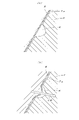
かくして、このような土構造物に生じたクラックや空隙などの欠陥を放置しておくと、漏水が発生し、崩壊等の事故に繋がる恐れがあることから、早期に修復する必要がある。そこで、土構造物に生じたクラック等を補修する方法として、図5に示すような前刃金工法が知られている。この前刃金工法は、ため池Wの堤体Tからなる土構造物に対して、刃金土Hを使用して、傾斜遮水ゾーンを構築するというものである。 Thus, if defects such as cracks and voids in such soil structures are left as they are, water leakage may occur, which may lead to accidents such as collapse. Therefore, early repair is required. Therefore, as a method for repairing cracks and the like generated in earthen structures, a front blade metalwork method as shown in FIG. 5 is known. This maehagane construction method is to construct an inclined impervious zone using hagane earth H for a soil structure consisting of a bank body T of a reservoir W.
ところで、このような前刃金工法は、漏水を防止することができるものの、昨今、使用する刃金土Hが枯渇しかかっており、採取しづらくなってきているという問題があった。 By the way, although such a front blade metal construction method can prevent water leakage, there is a problem that the blade metal soil H to be used is about to be depleted these days, making it difficult to collect it.
そこで、この前刃金工法の代替工法として、特許文献1に記載のような遮水シートを用いた工法が知られている。すなわち、この工法は、図6に示すように、堤体Tの斜面Taに遮水シートSを敷設し、この遮水シートSによって、漏水を防止するというものである。
Therefore, as an alternative construction method to the front blade metal construction method, a construction method using a waterproof sheet as described in
しかしながら、上記のような工法は、遮水シートSを敷設するにあたって、堤体Tの斜面Taを平滑にする必要があり、万が一、堤体Tの斜面Taに、図6(a)に示すような空隙Kが存在すると、この箇所から漏水が発生するという問題があった。或いは、遮水シートSが劣化することによって、パインピング現象が発生(図6(b)に示す矢印Y10参照)し、もって、図6(b)に示すように、遮水シートSが破損し、漏水が発生するという問題があった。そのため、遮水シートSを敷設するにあたっては、必ず、堤体Tの斜面Taを平滑にしなければならないといった問題があった。 However, in the construction method as described above, it is necessary to smooth the slope Ta of the bank body T when laying the impervious sheet S. If there is such a gap K, there is a problem that water leakage occurs from this location. Alternatively, when the impermeable sheet S deteriorates, a pinning phenomenon occurs (see arrow Y10 shown in FIG. 6B), and as a result, the impermeable sheet S is damaged as shown in FIG. 6B. , there was a problem of water leakage. Therefore, when laying the impervious sheet S, there is a problem that the slope Ta of the bank body T must be made smooth.
そこで、本発明は、上記問題に鑑み、土構造物の斜面を平滑にせずとも、漏水を防止することができる遮水層構築工法を提供することを目的としている。 Therefore, in view of the above problems, it is an object of the present invention to provide a construction method for constructing an impermeable layer that can prevent water leakage without smoothing the slope of the soil structure.
上記本発明の目的は、以下の手段によって達成される。なお、括弧内は、後述する実施形態の参照符号を付したものであるが、本発明はこれに限定されるものではない。 The above objects of the present invention are achieved by the following means. In addition, although the inside of parenthesis is attached with the reference code|symbol of embodiment mentioned later, this invention is not limited to this.
請求項1の発明によれば、土構造物(例えば、堤体T)の斜面(Ta)に対してベントナイト混合土(2)を段状に構築してなることを特徴としている。 According to the first aspect of the invention, the bentonite mixed soil (2) is built stepwise on the slope (Ta) of the soil structure (for example, the embankment body T).
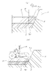
また、請求項2の発明によれば、上記請求項1に記載の遮水層構築工法において、前記土構造物(例えば、堤体T)の斜面(Ta)に対して所定の型枠(10)を設置し、その設置した所定の型枠(10)内にベントナイト混合土(2)を充填すると共に、その設置した所定の型枠(10)の外側に覆土(3)を撒き出す第1工程(図2(a)参照)と、
前記第1工程(図2(a)参照)が終了した後、前記所定の型枠(10)を引き抜き、前記ベントナイト混合土(2)と前記覆土(3)を転圧する第2工程(図2(b)参照)と、を含み、
前記第1工程(図2(a)参照)と前記第2工程(図2(b)参照)を繰り返し行うことにより、前記土構造物(例えば、堤体T)の斜面(Ta)に対して前記ベントナイト混合土(2)を段状に構築してなることを特徴としている。
According to the invention of
After the first step (see FIG. 2(a)) is completed, the predetermined formwork (10) is pulled out, and the bentonite mixed soil (2) and the cover soil (3) are rolled and compacted in the second step (see FIG. 2 (b)), including
By repeating the first step (see FIG. 2(a)) and the second step (see FIG. 2(b)), the slope (Ta) of the soil structure (for example, bank body T) It is characterized in that the bentonite mixed soil (2) is constructed stepwise.
次に、本発明の効果について、図面の参照符号を付して説明する。なお、括弧内は、後述する実施形態の参照符号を付したものであるが、本発明はこれに限定されるものではない。 Next, the effects of the present invention will be described with reference to the drawings. In addition, although the inside of parenthesis is attached with the reference code|symbol of embodiment mentioned later, this invention is not limited to this.
請求項1に係る発明によれば、土構造物(例えば、堤体T)の斜面(Ta)に対して土質材料であるベントナイト混合土(2)を段状に構築しているから、土構造物の斜面を平滑にせずとも、漏水を防止することができる。 According to the first aspect of the invention, the bentonite mixed soil (2), which is a soil material, is stepped on the slope (Ta) of the soil structure (for example, the embankment body T). Leakage can be prevented without smoothing the slope of the object.
請求項2に係る発明によれば、土構造物(例えば、堤体T)の斜面(Ta)に対して所定の型枠(10)を設置し、その設置した所定の型枠(10)内にベントナイト混合土(2)を充填すると共に、その設置した所定の型枠(10)の外側に覆土(3)を撒き出し、その後、所定の型枠(10)を引き抜き、ベントナイト混合土(2)と覆土(3)を転圧するという工程を繰り返し行うことにより、土構造物(例えば、堤体T)の斜面(Ta)に対してベントナイト混合土(2)を段状に構築するようにしている。これにより、簡単容易に、土構造物(例えば、堤体T)の斜面(Ta)に対してベントナイト混合土(2)を段状に構築することができる。さらには、所定の型枠(10)内にベントナイト混合土(2)を充填すると共に、その設置した所定の型枠(10)の外側に覆土(3)を撒き出しするようにしているから、ベントナイト混合土(2)と覆土(3)を簡単容易に構築することが可能となる。
According to the invention of
以下、本発明に係る遮水層構築工法の一実施形態を、図面を参照して具体的に説明する。なお、以下の説明において、上下左右の方向を示す場合は、図示正面から見た場合の上下左右をいうものとする。 Hereinafter, one embodiment of the impermeable layer construction method according to the present invention will be specifically described with reference to the drawings. In the following description, when the directions of up, down, left, and right are indicated, they refer to up, down, left, and right when viewed from the front of the drawing.
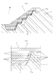
図1(a)に示すように、本実施形態に係る遮水層1は、例えば、ため池Wの堤体Tからなる土構造物の斜面Taに対して、段状に構築されるものである。より詳しく説明すると、図1(b)に示すように、遮水層1は、堤体Tの斜面Taに沿って、段状に構築されているベントナイト混合土2と、ベントナイト混合土2のため池W側の側面に構築されている覆土3と、で構成されている。このベントナイト混合土2は、母材となる砂質系土砂にベントナイトを一定量混合して得られる材料である。ベントナイトは、天然の粘土鉱物であり、吸水により膨潤する性質を有している。そのため、この膨潤性によって高い遮水性や自己修復性(損傷などの理由によって低下した遮水性が、徐々に回復する性質)の発揮が期待できる。それゆえ、このベントナイト混合土2は、ベントナイトの膨潤性により、母材の遮水性の改善が可能となる。また、ベントナイト混合土2で使用するベントナイトは、無機土質材料のため、長期的にみても不燃性で劣化・分解することが無く半永久的に遮水機能を保つことができる。なお、本実施形態においては、ベントナイト混合土2の透水係数を1×10⁻⁶cm/sec以下にすることによって(図5に示す刃金土Hの透水係数は1×10-5cm/sec)、薄層化を実現し、もって、コストダウンを図れるようにしている。
As shown in FIG. 1(a), the
以下、この遮水層1を構築する方法を具体的に説明することとする。
A method for constructing the
<遮水層を構築する方法の説明>
遮水層1を構築するにあたっては、まず、図2(a)に示すように、堤体Tの斜面Taの最下面Ta1にベントナイト混合土2を充填し、約20cm程度の厚みのベントナイト混合土2の層を構築する。
<Description of how to construct the impermeable layer>
In constructing the
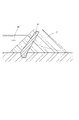
次いで、図3に示すような型枠10を使用する。この型枠10は、金属等で形成されており、図3に示すように、上面10aが開放され、下面10bが開放され、左側面10cが閉止され、右側面10dが閉止され、前面10eが閉止され、後面10fが開放された横長の逆台形状に形成されている。そして、図3に示すように、このような型枠10の左側面10cの上面10a側には、コ字状の左把持部10c1が一体的に設けられ、型枠10の右側面10dの上面10a側には、コ字状の右把持部10d1が一体的に設けられている。
A
かくして、このように形成される型枠10は、堤体Tの斜面Taの最下面Ta1に構築されているベントナイト混合土2の層上に設置されると共に、図4に示すように、堤体Tの斜面Ta側に後面10fが位置するように設置される。そして、このように設置された型枠10は、堤体Tの斜面Taの長手方向に沿って、横並びに複数並設される。しかして、この状態で、図4に示すように、油圧ショベル(図示せず)のバケットBを用いて、型枠10の上面10a側から、型枠10内にベントナイト混合土2が充填されることとなる。この際、型枠10の後面10fが開放されているから、型枠10内にベントナイト混合土2を充填するだけで、ベントナイト混合土2を堤体Tの斜面Taに簡単容易に配置させることができる。しかして、複数並設された型枠10内にベントナイト混合土2が充填されると、型枠10の前面10e側に、覆土3が撒き出しされることとなる。
Thus, the
かくして、このように、型枠10内にベントナイト混合土2が充填され、型枠10の前面10e側に、覆土3が撒き出しされると、図2(a)に示すように、型枠10が矢印Y1方向に引き抜かれることとなる。この際、型枠10の下面10bが開放されているから、型枠10を引き抜いた際、型枠10内に充填されたベントナイト混合土2を、堤体Tの斜面Taに残置することができる。なお、型枠10を引き抜く際、型枠10の左把持部10c1及び右把持部10d1にワイヤー等が取り付けられ、引き抜かれることとなる。
Thus, when the
次いで、図2(b)に示すように、従来周知の構造である転圧機Rを用いて、覆土3及びベントナイト混合土2を転圧し、約20cm程度の厚みの覆土3及びベントナイト混合土2の層を構築する。
Next, as shown in FIG. 2(b), the
かくして、上記のような型枠10及び転圧機Rを用いて、上記説明した処理を繰り返し行うことにより、約20cm程度の厚みの覆土3及びベントナイト混合土2の層を段状に形成することができることとなる。これにより、図1(a)に示すような、遮水層1が、堤体Tの斜面Taに構築されることとなる。
Thus, by repeating the processing described above using the
しかして、以上説明した本実施形態に示す方法にて、堤体Tの斜面Taに対してベントナイト混合土2を段状に構築するようにすれば、堤体Tの斜面を平滑にせずとも、漏水を防止することができる。すなわち、ベントナイト混合土2は、土質材料であるから、堤体Tの斜面Taが平滑になっておらず岩などが出て凹凸形状になっていたとしても、その凹凸部分にベントナイト混合土2が入り込んで馴染むこととなり、もって、パインピングの原因となる図6(b)に示すような空隙Kが堤体Tの斜面Taに形成される事態を防止することができる。それゆえ、堤体Tの斜面Taに対してベントナイト混合土2を段状に構築するようにすれば、堤体Tの斜面Taを平滑にせずとも、漏水を防止することができる。
Therefore, if the bentonite
また、本実施形態においては、堤体Tの斜面Taに対して型枠10を設置し、その設置した型枠10内にベントナイト混合土2を充填すると共に、その設置した型枠10の前面10a側に覆土3を撒き出し、その後、型枠10を引き抜き、ベントナイト混合土2と覆土3を転圧するという工程を繰り返し行うことにより、堤体Tの斜面Taに対してベントナイト混合土2を段状に構築することができる。これにより、簡単容易に、堤体Tの斜面Taに対してベントナイト混合土2を段状に構築することができる。
Further, in this embodiment, a
さらに、本実施形態においては、型枠10内にベントナイト混合土2を充填し、型枠10の前面10e側に、覆土3を撒き出しするようにしているから、ベントナイト混合土2と覆土3を簡単容易に構築することが可能となる。
Furthermore, in the present embodiment, the
なお、本実施形態において示した遮水層を構築する方法はあくまで一例であり、特許請求の範囲に記載された本発明の要旨の範囲内において種々の変形・変更が可能である。例えば、本実施形態においては、土構造物として、ため池Wの堤体Tを例にして説明したが、それに限らず、漏水を防止する箇所であれば、汚染水等、どのような箇所にも適用可能である。 The method of constructing the impermeable layer shown in this embodiment is merely an example, and various modifications and changes are possible within the scope of the present invention described in the scope of claims. For example, in the present embodiment, the embankment body T of the reservoir W was described as an example of the soil structure. Applicable.
1 遮水層
2 ベントナイト混合土
3 覆土
10 型枠(所定の型枠)
T 堤体(土構造物)
Ta 斜面
1
T Embankment body (soil structure)
Ta slope
Claims (2)
前記第1工程が終了した後、前記所定の型枠を引き抜き、前記ベントナイト混合土と前記覆土を転圧する第2工程と、を含み、
前記第1工程と前記第2工程を繰り返し行うことにより、前記土構造物の斜面に対して前記ベントナイト混合土を段状に構築してなる請求項1に記載の遮水層構築工法。
A predetermined formwork is installed on the slope of the soil structure, the bentonite mixed soil is filled in the established formwork, and the cover soil is spread outside the established formwork. process and
After the first step is completed, the predetermined formwork is pulled out, and a second step of rolling the bentonite mixed soil and the covering soil,
2. The impermeable layer constructing method according to claim 1, wherein the bentonite mixed soil is constructed stepwise on the slope of the earth structure by repeating the first step and the second step.
Priority Applications (1)
| Application Number | Priority Date | Filing Date | Title |
|---|---|---|---|
| JP2021113238A JP7295538B2 (en) | 2021-07-08 | 2021-07-08 | Impermeable layer construction method |
Applications Claiming Priority (1)
| Application Number | Priority Date | Filing Date | Title |
|---|---|---|---|
| JP2021113238A JP7295538B2 (en) | 2021-07-08 | 2021-07-08 | Impermeable layer construction method |
Publications (2)
| Publication Number | Publication Date |
|---|---|
| JP2023009727A true JP2023009727A (en) | 2023-01-20 |
| JP7295538B2 JP7295538B2 (en) | 2023-06-21 |
Family
ID=85118266
Family Applications (1)
| Application Number | Title | Priority Date | Filing Date |
|---|---|---|---|
| JP2021113238A Active JP7295538B2 (en) | 2021-07-08 | 2021-07-08 | Impermeable layer construction method |
Country Status (1)
| Country | Link |
|---|---|
| JP (1) | JP7295538B2 (en) |
Cited By (1)
| Publication number | Priority date | Publication date | Assignee | Title |
|---|---|---|---|---|
| CN118547637A (en) * | 2024-07-25 | 2024-08-27 | 云南建投第一水利水电建设有限公司 | Strong karst area reservoir engineering dam foundation seepage-proofing treatment equipment and treatment process |
Citations (5)
| Publication number | Priority date | Publication date | Assignee | Title |
|---|---|---|---|---|
| JPH05306523A (en) * | 1992-04-28 | 1993-11-19 | Mitsui Constr Co Ltd | Banking work |
| JPH08209679A (en) * | 1995-02-03 | 1996-08-13 | Seibu Kensetsu Kk | Inside slope structure of waste disposal site |
| JPH11216439A (en) * | 1998-02-02 | 1999-08-10 | Seibu Construction Co Ltd | Construction method of impermeable layer such as slope, impermeable layer such as slope and sandbag manufacturing equipment |
| JP2012144937A (en) * | 2011-01-14 | 2012-08-02 | Railway Technical Research Institute | Banking-reinforcing soil wall construction method and temporary holding material for banking-reinforcing soil wall for use in the same |
| JP2012207434A (en) * | 2011-03-29 | 2012-10-25 | National Agriculture & Food Research Organization | Construction method of wall body structure and wall body structure constructed by the method |
-
2021
- 2021-07-08 JP JP2021113238A patent/JP7295538B2/en active Active
Patent Citations (5)
| Publication number | Priority date | Publication date | Assignee | Title |
|---|---|---|---|---|
| JPH05306523A (en) * | 1992-04-28 | 1993-11-19 | Mitsui Constr Co Ltd | Banking work |
| JPH08209679A (en) * | 1995-02-03 | 1996-08-13 | Seibu Kensetsu Kk | Inside slope structure of waste disposal site |
| JPH11216439A (en) * | 1998-02-02 | 1999-08-10 | Seibu Construction Co Ltd | Construction method of impermeable layer such as slope, impermeable layer such as slope and sandbag manufacturing equipment |
| JP2012144937A (en) * | 2011-01-14 | 2012-08-02 | Railway Technical Research Institute | Banking-reinforcing soil wall construction method and temporary holding material for banking-reinforcing soil wall for use in the same |
| JP2012207434A (en) * | 2011-03-29 | 2012-10-25 | National Agriculture & Food Research Organization | Construction method of wall body structure and wall body structure constructed by the method |
Cited By (1)
| Publication number | Priority date | Publication date | Assignee | Title |
|---|---|---|---|---|
| CN118547637A (en) * | 2024-07-25 | 2024-08-27 | 云南建投第一水利水电建设有限公司 | Strong karst area reservoir engineering dam foundation seepage-proofing treatment equipment and treatment process |
Also Published As
| Publication number | Publication date |
|---|---|
| JP7295538B2 (en) | 2023-06-21 |
Similar Documents
| Publication | Publication Date | Title |
|---|---|---|
| CN104153380B (en) | A kind of antiseepage cofferdam structure and construction technology | |
| CN103806432B (en) | Method for treating foundations in slope filling and digging joint part of wet and soft zone in loess region | |
| CN116397475B (en) | In-situ reconstruction and expansion structure of embankment and construction method | |
| CN103882884A (en) | Anchor rope geogrid retaining structure and method for constructing same | |
| CN106522244B (en) | A kind of embankment combination binding structure and its construction method | |
| CN104264680A (en) | Foundation treatment method of collapsible loess slope cut-and-fill joint part | |
| CN105804007B (en) | A kind of reinforced earth quaywall structure based on the soft base of beach | |
| CN111733842A (en) | Cofferdam construction method and cofferdam structure | |
| CN102444143A (en) | Construction method for canceling out underground outdoor vertical face operation channel | |
| KR101531799B1 (en) | Repair reinforcement method of the waterfront structure | |
| CN111648348A (en) | Method for processing high-rise building foundation in non-self-weight collapsible loess area | |
| JP7295538B2 (en) | Impermeable layer construction method | |
| KR102503396B1 (en) | Waste material buried place making method | |
| JP4575800B2 (en) | Embankment reinforcement structure and reinforcement method | |
| JP5204063B2 (en) | Box foundation construction method in open shield method | |
| JP2004108142A (en) | Method for construction of a control type revetment | |
| CN115652719A (en) | A load-bearing embankment structure of wall-pile-net composite foundation | |
| CN109113045A (en) | A kind of soft-soil foundation treatment method | |
| CN114575355A (en) | Soil protection and descent construction method | |
| CN110804994B (en) | Reservoir dam construction method | |
| CN110144935B (en) | Soft and hard abrupt stratum open cut cable tunnel structure | |
| TWI623669B (en) | Construction method of advance pavement for preventing underground subsidence before continuous wall construction | |
| CN114232587A (en) | Construction method for preventing settlement and cracking of large-area ground | |
| CN207211176U (en) | A kind of big open caisson of superelevation | |
| RU2654906C2 (en) | Method of reconstruction of barrow pits for building of cemetery |
Legal Events
| Date | Code | Title | Description |
|---|---|---|---|
| A621 | Written request for application examination |
Free format text: JAPANESE INTERMEDIATE CODE: A621 Effective date: 20220620 |
|
| A131 | Notification of reasons for refusal |
Free format text: JAPANESE INTERMEDIATE CODE: A131 Effective date: 20230201 |
|
| A521 | Request for written amendment filed |
Free format text: JAPANESE INTERMEDIATE CODE: A523 Effective date: 20230317 |
|
| TRDD | Decision of grant or rejection written | ||
| A01 | Written decision to grant a patent or to grant a registration (utility model) |
Free format text: JAPANESE INTERMEDIATE CODE: A01 Effective date: 20230510 |
|
| A61 | First payment of annual fees (during grant procedure) |
Free format text: JAPANESE INTERMEDIATE CODE: A61 Effective date: 20230601 |
|
| R150 | Certificate of patent or registration of utility model |
Ref document number: 7295538 Country of ref document: JP Free format text: JAPANESE INTERMEDIATE CODE: R150 |