JP2023034603A - Control system for one-sided alternate passage and traffic light - Google Patents
Control system for one-sided alternate passage and traffic light Download PDFInfo
- Publication number
- JP2023034603A JP2023034603A JP2021140919A JP2021140919A JP2023034603A JP 2023034603 A JP2023034603 A JP 2023034603A JP 2021140919 A JP2021140919 A JP 2021140919A JP 2021140919 A JP2021140919 A JP 2021140919A JP 2023034603 A JP2023034603 A JP 2023034603A
- Authority
- JP
- Japan
- Prior art keywords
- traffic
- vehicle
- camera
- lane
- control
- Prior art date
- Legal status (The legal status is an assumption and is not a legal conclusion. Google has not performed a legal analysis and makes no representation as to the accuracy of the status listed.)
- Granted
Links
Images






Landscapes
- Traffic Control Systems (AREA)
- Image Analysis (AREA)
Abstract
Description
本発明は、片側交互通行を効率よく行う制御システムと交通信号機に関する。特に、片側交互通行区間に進入してくる車両の台数と走行状態を把握し、能動的に信号機の切り替えを行う制御システムに関する。また、片側交互通行を効率よく行うことのできる交通信号機に関する。 The present invention relates to a control system and a traffic signal for efficiently performing alternating one-way traffic. In particular, the present invention relates to a control system for actively switching traffic lights by grasping the number of vehicles entering a one-way alternate traffic section and their running conditions. The present invention also relates to a traffic signal capable of efficiently performing alternating one-way traffic.
道路工事等によって道路の幅員が不足し、車両がすれ違いできない場合に、一つの車線だけを用いて車両を交互に通行させる片側交互通行が行われる。双方の車線の車両を交互に通行させる方法としては、工事用の交通信号機による方法と、交通誘導員による手動の方法がある。現在最も普及している工事用の交通信号機は、事前に設定した一定の時間で信号を自動的に切り替える受動的制御が採用されている。このような交通信号機では、交通量が多くなると最適な制御が行われず、一方の車線だけが渋滞するといった問題が生じることがある。これに対して、熟練した交通誘導員は、安全に配慮しつつ、単位時間あたりで片側交互通行区間を通過する車両数を最大化する車線の切り替え方法、または両方の車線の平均待ち時間を最小化する車線の切り替え方法を経験的に学んでおり、交通信号機よりも、よりスムーズな片側交互通行を実現できる場合がある。 When the width of the road is insufficient due to road construction or the like and vehicles cannot pass each other, one-way alternate traffic is performed in which vehicles alternately pass by using only one lane. As a method for alternately passing vehicles on both lanes, there are a method using a traffic signal for construction and a manual method by a traffic director. Traffic signals for construction work, which are currently the most popular, employ passive control that automatically switches signals at a predetermined time. With such a traffic signal, when the traffic volume increases, optimal control is not performed, and a problem may arise that only one lane is congested. In contrast, a skilled traffic director should consider a lane-switching method that maximizes the number of vehicles crossing the alternating one-way section per unit time, or minimizes the average waiting time for both lanes, while keeping safety in mind. We have learned empirically how to switch between lanes in a timely manner, and in some cases it is possible to realize a smoother one-way alternate traffic than traffic lights.
一方で、交通誘導員の育成には相当な期間が必要であり、熟練した交通誘導員は慢性的に不足している。現状では、全ての片側交互通行区間に交通誘導員を配置することは困難であり、交通信号機が随所で利用されている。このため、交通信号機による赤信号と青信号の時間間隔を最適化し、安全でかつ待ち時間が少なくなるように、交通整理を行うことのできる技術が求められている。 On the other hand, it takes a considerable amount of time to train traffic directors, and there is a chronic shortage of skilled traffic directors. Currently, it is difficult to allocate traffic guides to all alternating one-way sections, and traffic signals are used everywhere. Therefore, there is a demand for a technology that optimizes the time interval between the red and green lights of a traffic signal and controls traffic in a safe and short waiting time.
特許文献1には、車両感知器、可視カメラ、または赤外線カメラを備え、道路工事のために設けられた停止線で信号待ちをしている車両を検知し、この情報をもとに渋滞が緩和できるように信号機の表示時間を調整する道路工事交通信号制御装置が開示されている。特許文献1の信号制御装置は、カメラの映像の中で車両が占有している車両占有範囲を計測し、渋滞の指標としている。しかし、片側交互通行区間に到達するまでの、個々の車両の走行状態や、走行時の車両同士の車間距離などを、信号機制御の指標として用いておらず、交通誘導員による誘導よりも効率の悪い制御となる可能性がある。
In
より効率のよい片側交互通行を信号機で実現するためには、遠距離から近づいてくる車両の走行状態を把握することが重要である。従来から、カメラによって道路とその周辺の画像を取得し、深層学習をおこなったプログラムによって車両を検出する技術が行われている。非特許文献1には、画像内で比較的大きな領域を占めている、近距離や中距離にある車両を検出する技術が開示されている。しかしながら、遠距離にあって画像内に小さく映っている車両をいち早く検出する検討は、これまであまり行われていない。
In order to realize more efficient one-way alternating traffic with traffic lights, it is important to grasp the running state of vehicles approaching from a long distance. Conventionally, a technology has been used in which images of a road and its surroundings are acquired by a camera, and vehicles are detected by a program that has undergone deep learning. Non-Patent
片側交互通行区間の交通整理を、安全かつより効率よく行い、渋滞を最小限にすることのできる制御システムが求められている。特に、片側交互通行区間に侵入してくる車両の台数と走行状態を分析し、得られた分析結果に基づいて、信号の切り替えを能動的に行う制御システムが求められている。さらに、能動的な制御システムを搭載して、より安全で効率よく片側交互通行を実現することのできる交通信号機が求められている。 There is a need for a control system that can safely and more efficiently direct traffic on alternating one-way sections to minimize congestion. In particular, there is a demand for a control system that analyzes the number of vehicles entering a one-way alternate traffic section and the running conditions, and actively switches signals based on the obtained analysis results. Further, there is a need for a traffic signal that incorporates an active control system to provide safer and more efficient alternating one-way traffic.
本発明は、上記解決すべき課題に鑑みてなされたものであって、片側交互通行区間の交通整理を、従来よりも安全かつより効率よく行うことのできる制御システムと交通信号機の提供を、解決すべき課題としてなされたものである。 The present invention has been made in view of the above problems to be solved, and aims to provide a control system and a traffic signal that can control traffic in alternating one-way traffic sections more safely and efficiently than before. This was made as an issue that should be addressed.
本発明は、片側交互通行の制御システムに関する。本発明の制御システムは、一方の車線の遠方から停止位置までを撮影する第一のカメラと、他方の車線の遠方から停止位置までを撮影する第二のカメラと、第一のカメラと第二のカメラが撮影した画像を用いてそれぞれの車線における車両の状態を取得し、信号機の判断ロジックを制御する制御用コンピュータとを、備えている。本発明の片側交互通行の制御システムは、制御用コンピュータが、少なくとも、片側交互通行区間を通過する単位時間あたりの車両の通行台数を正の報酬とし、かつ停止位置で停車する車両の平均停車時間を負の報酬として、その報酬が最大となる判断ロジックを学習した制御プログラムを記憶していることを特徴とする。 The present invention relates to a control system for alternating one-way traffic. The control system of the present invention includes a first camera that captures an image of one lane from a distance to a stop position, a second camera that captures an image of the other lane from a distance to the stop position, the first camera and the second camera. and a control computer for acquiring the state of the vehicle in each lane using the image captured by the camera, and for controlling the decision logic of the traffic light. In the alternate one-way traffic control system of the present invention, the control computer uses at least the number of vehicles passing per unit time passing through the alternate one-way traffic section as a positive reward, and the average stop time of vehicles stopping at a stop position. is a negative reward, and a control program that has learned a judgment logic that maximizes the reward is stored.
本発明の片側交互通行の制御システムにおいて、制御プログラムの学習は、それぞれの車線の車両出現時刻間隔の確率、それぞれの車両の前車がいない場合の車速の確率密度分布、及びそれぞれの車両の前車がいる場合の車速に応じた車間距離の確率密度分布をパラメータとするシミュレータが生成するデータに対して、所定の判断ロジックを一定時間継続したときの報酬を評価することを繰り返すことにより、報酬が最大となる判断ロジックを学習させるものであることが好ましい。 In the alternate one-way traffic control system of the present invention, learning of the control program includes the probability of vehicle appearance time intervals in each lane, the probability density distribution of vehicle speed when there is no vehicle in front of each vehicle, and the probability density distribution of vehicle speed when there is no vehicle in front of each vehicle. By repeatedly evaluating the reward when the predetermined judgment logic is continued for a certain period of time for the data generated by the simulator whose parameter is the probability density distribution of the inter-vehicle distance according to the vehicle speed when there is a car, It is preferable to learn the judgment logic that maximizes the .
本発明の制御システムの制御用コンピュータは、第一のカメラまたは第二のカメラが撮影した画像を用いて遠方に存在する車両を抽出する画像処理部を備えていることが好ましい。この場合において、画像処理部は、車両の特異点(本発明の画像処理部で特定された消失点は、一般的な手法で特定される消失点とは異なる位置となる場合があるため、本発明の手法で特定される消失点を、以下「特異点」という。)から規則的に移動する物体を車両として抽出する処理を行うことを特徴とする。 The control computer of the control system of the present invention preferably includes an image processing section that extracts a distant vehicle using an image captured by the first camera or the second camera. In this case, the image processing unit determines the singular point of the vehicle (the vanishing point specified by the image processing unit of the present invention may be at a different position from the vanishing point specified by a general method. The vanishing point specified by the method of the invention is hereinafter referred to as a "singular point".
画像処理部が遠方に存在する車両を抽出する場合、車両の特異点は、画像処理部が、前記画像中の動きベクトル方向のヒストグラムが180度ずれた2つのピークを形成する領域を関心領域とし、前記関心領域内の動きベクトルのストリームラインを導出し、導出された複数のストリームラインの終末点の位置から推定される。 When the image processing unit extracts a vehicle existing in the distance, the singular point of the vehicle is determined by the image processing unit as a region of interest where the histogram of the motion vector direction in the image forms two peaks shifted by 180 degrees. , derive streamlines of motion vectors in the region of interest, and are estimated from the positions of the end points of the derived streamlines.
本発明はまた、片側交互通行用の交通信号機を提供する。本発明の交通信号機は、それぞれの車線に配置される一対の信号機と、カメラの撮影した画像を用いて、それぞれの車線における車両の状態を取得し、前記信号機の判断ロジックを制御する制御用コンピュータと、を備えている。制御用コンピュータが用いる画像は、一方の車線の遠方から停止位置までを撮影する第一のカメラと、他方の車線の遠方から停止位置までを撮影する第二のカメラとがそれぞれ撮影した画像である。本発明の交通信号機は、制御用コンピュータが、少なくとも、片側交互通行区間を通行する単位時間あたりの車両の通行台数を正の報酬とし、かつ停止位置で停車する車両の平均停車時間を負の報酬として、その報酬が最大となる判断ロジックを学習した制御プログラムを記憶している。一対の信号機は、制御プログラムの制御によって、その表示内容と表示時間を変更することを特徴とする。 The present invention also provides a traffic signal for alternating one-way traffic. The traffic signal of the present invention acquires the state of the vehicle in each lane using a pair of traffic signals placed in each lane and an image captured by a camera, and a control computer that controls the judgment logic of the traffic signal. and have. The images used by the control computer are images captured by a first camera that captures an image of one lane from a distance to the stop position, and an image captured by a second camera that captures an image of the other lane from a distance to the stop position. . In the traffic signal of the present invention, the control computer gives a positive reward for at least the number of vehicles passing through the one-way alternate traffic section per unit time, and gives a negative reward for the average stopping time of the vehicles stopping at the stop position. , the control program that learned the judgment logic that maximizes the reward is stored. The pair of traffic lights are characterized by changing their display contents and display time under the control of a control program.
本発明の片側交互通行の制御システムは、遠方から停止位置まで近づいてくる車両を撮影してそれぞれの車線における車両の状態を取得することで、従来よりも精度高く車両の通行状態を把握し、効率よく片側交互通行の誘導を行うすることができる。 The control system for alternating one-way traffic of the present invention acquires the vehicle status in each lane by photographing vehicles approaching the stop position from a distance, thereby grasping the traffic status of the vehicle with higher accuracy than before, It is possible to efficiently guide one-way alternate traffic.
本発明の制御システムは、制御プログラムの判断ロジックの学習に、単位時間あたりの通行台数と、停車している車両の平均停車時間を報酬とした学習モデルを用いることにより、判断ロジックの機械学習を可能とし、熟練の交通整理員に匹敵する判断ロジックの習得を可能とする。 The control system of the present invention uses a learning model that rewards the number of traffic per unit time and the average stopping time of stopped vehicles for learning the judgment logic of the control program, thereby performing machine learning of the judgment logic. It is possible to acquire judgment logic comparable to that of a skilled traffic controller.
本発明の制御システムは、画像処理部を備えることにより、従来よりも遠方から片側交互通行区間に近づいてくる車両を識別することが可能となる。遠方からの車両を識別することで、各車両の走行状態がより正確に把握され、一層効率の良い片側交互通行の制御が可能となる。 Since the control system of the present invention includes an image processing unit, it becomes possible to identify a vehicle approaching a one-way alternate traffic section from a farther distance than the conventional one. By identifying vehicles from a distance, the running conditions of each vehicle can be grasped more accurately, and more efficient one-way alternate traffic control becomes possible.
本発明の交通信号機は、カメラを撮影した遠方から停止位置まで近づいてくる車両の画像によってそれぞれの車線における車両の状態を取得した制御プログラムの制御によって、効率よく片側交互通行のための信号の切り替えを行うことができる。 The traffic signal of the present invention efficiently switches signals for alternating one-way traffic under the control of a control program that acquires the state of vehicles in each lane from images captured by a camera of vehicles approaching from a distance to a stop position. It can be performed.
以下、本発明の片側交互通行の制御システムおよび交通信号機について、図面を参照しつつ詳細に説明する。本実施形態では、最初に、制御システムの構成の概要を説明し、次に、制御用コンピュータを備えた交通信号機の構成を説明する。 Hereinafter, a control system for alternating one-way traffic and a traffic signal according to the present invention will be described in detail with reference to the drawings. In this embodiment, first, an overview of the configuration of the control system will be described, and then the configuration of a traffic signal equipped with a control computer will be described.
本実施形態の片側交互通行の制御システムは、一方の車線の遠方から停止位置までを撮影する第一のカメラと、他方の車線の遠方から停止位置までを撮影する第二のカメラと、第一のカメラと第二のカメラの画像を用いてそれぞれの車線における車両の状態を取得し、信号機の判断ロジックを制御する制御用コンピュータとを備えている。 The control system for alternating one-way traffic of this embodiment includes a first camera that captures an image of one lane from a distance to a stop position, a second camera that captures an image of the other lane from a distance to the stop position, and a first camera. and a control computer that acquires the vehicle state in each lane using the images of the second camera and the second camera and controls the decision logic of the traffic light.
図1に、制御システムの制御用コンピュータ1の構成を、ブロック図で示す。本発明の制御用コンピュータは、制御用プログラムと画像処理部を備えている。本実施形態の制御用コンピュータは一台のコンピュータで構成されており、交互通行を行う一方の車線と他方の車線の交通状態の両方を集約している。
FIG. 1 shows a block diagram of the configuration of a
交通誘導員による片側交互通行の誘導は、通常一つの車線につき一人の人員が担当し、トランシーバー等の通信手段で連絡をとりつつ誘導を行う。このような方法では、反対側に停車中の車両の数、停車時間などの情報は十分に得られにくいという問題があった。これに対して、本実施形態では、両方の車線の状況を一台の制御用コンピュータ1に集約するため、より効率的な制御が可能となる。
Normally, one person per lane is in charge of one-way alternate traffic guidance by traffic guides, and guidance is provided while communicating with communication means such as walkie-talkies. With such a method, there is a problem that it is difficult to sufficiently obtain information such as the number of vehicles stopped on the opposite side and the stop time. On the other hand, in this embodiment, since the conditions of both lanes are integrated into one
片側交互通行の効率的な交通制御は、片側交互通行区間の以下のような特性を考慮して行うことが好ましい。
・ 両方の車線の交通量(単位時間当たりの通行台数)
・ 片側交互通行区間に到達する前の、それぞれの車両の平均車速
・ 片側交互通行区間に到達する前の、それぞれの車両の平均加速度
・ 車両が数台から数十台で連なった「車塊」の状態で到達する場合の、それぞれの車両出現時刻間隔の確率。
・ それぞれの車両の前車がいない場合の車速の確率密度分布。
・ それぞれの車両の前車がいない場合の加速度の確率密度分布。
・ それぞれの車両の前車がいる場合の車速に応じた車間距離の確率密度分布。
Efficient traffic control of alternating one-way traffic should preferably be performed by considering the following characteristics of alternating one-way traffic sections.
・ Traffic volume in both lanes (number of traffic per unit time)
・The average vehicle speed of each vehicle before reaching the one-way alternate traffic section ・The average acceleration of each vehicle before reaching the one-way alternate traffic section The probability of each vehicle appearance time interval when arriving in the state of .
- Probability density distribution of vehicle speed when there is no vehicle in front of each vehicle.
• Probability density distribution of acceleration when there is no vehicle in front of each vehicle.
・ Probability density distribution of inter-vehicle distance according to vehicle speed when there is a vehicle in front of each vehicle.
これらの特性を考慮して、それぞれの車線に備えられた信号機の青と赤の切り替えを行うために、本実施形態の制御用コンピュータの制御プログラムは、交通シミュレータを用いて深層学習を行い、様々な交通状態に対応可能な最適制御を学習している。 In consideration of these characteristics, the control program of the control computer of the present embodiment uses a traffic simulator to perform deep learning and various It learns optimal control that can respond to various traffic conditions.
図2に制御プログラムの強化学習を行うための交通シミュレータの概念を示す。図中、符号Cが付された一つ一つの正方形は、それぞれの車線を走行する車両を表している。符号3が付された丸印は一方の車線を制御する信号機であり、符号4が付された丸印は他方の車線を制御する信号機である。シミュレータ上では、片側交互通行区間は、両方の車線を横断する領域で示されており、この区間は、いずれか一方の車線を車線が走行しているとき、他方はこの領域に侵入しないことが定義されている。
Figure 2 shows the concept of a traffic simulator for reinforcement learning of control programs. In the figure, each square with a symbol C represents a vehicle traveling in each lane. A circle marked with a
交通シミュレータは、車両Cごとに、信号機3,4の中心を原点とする座標と、速度と、加速度のデータを与える。そして、車両Cごとに、以下の3つの条件を定義している。
・ 指定速度以下なら加速する。
・ 走行する車線の前方の信号機3,4が赤の場合は、減速する。
・ 前の車両Cとの距離が近づいたら減速する。
For each vehicle C, the traffic simulator provides coordinates with the center of the
・ Accelerate if the speed is less than the specified speed.
・ If the
・ When the distance to the preceding vehicle C approaches, the vehicle decelerates.
図3に、制御プログラムが交通シミュレータを用いて行う強化学習の方法をブロック図で示す。交通シミュレータは、制御プログラムに、車両Cごとのデータである、座標、速度、加速度の値を持つ配列、

制御プログラムは、車両Cごとのデータを受け取り、交通シミュレータ内で、信号機3、4を赤と青のどちらか一方に制御するという行動を決定する。交通制御を開始した初期段階では、反対車線の信号が赤で、かつ片側交互通行区間に車両Cがいない時に、青信号に切り替えるという最も簡単な規則のみが定められている。なお、以下においては、信号機3、4を両方とも赤に制御した状態を行動1の「赤々」と略称する。また、信号機3が赤で信号機4を青に制御した状態を行動2の「赤青」、信号機3が青で信号機4を赤に制御した状態を行動3の「青赤」と略称する。
The control program receives data for each vehicle C and determines actions within the traffic simulator to control the
制御プログラムの行動の結果に対する正の報酬は、片側交互通行区間を通過する単位時間あたりの車両Cの通行台数と規定されている。一方、停止位置で停車する車両Cの平均停車時間を負の報酬と規定されている。これに加えて、急ブレーキを発生させたとき、その減速加速度の大きさと割合に応じた負の報酬が規定されている。 A positive reward for the result of the action of the control program is defined as the number of vehicles C passing per unit time through the alternating one-way section. On the other hand, the average stop time of vehicle C stopped at the stop position is defined as a negative reward. In addition to this, when a sudden brake is generated, a negative reward according to the magnitude and rate of deceleration acceleration is stipulated.
制御プログラムは、交通制御を交通シミュレータから与えられた車両Cのデータを用いて、交通制御を一定時間行う。そして、制御の完了時の報酬を評価し、その都度判断ロジックを修正してゆき、その報酬を最大にするように学習を繰り返す。最初にある程度適した行動をとるようになるとその行動をとり続けてしまうため、本実施形態では、εの値に則ってランダムな行動を起こさせるε-greedy法を用いて最適の行動を探し続ける。さらに、交通シミュレータは、想定しうる様々な交通属性に基づいて車両Cのデータを制御プログラムに与え、同様に交通制御を繰り返すことにより、様々な交通状態に適応できる最適な交通制御ロジックが獲得される。 The control program performs traffic control for a certain period of time using vehicle C data given from the traffic simulator. Then, the reward at the time of completion of control is evaluated, the judgment logic is corrected each time, and learning is repeated so as to maximize the reward. In the present embodiment, the ε-greedy method, in which a random action is taken according to the value of ε, is used to continuously search for the optimum action. . Furthermore, the traffic simulator provides the control program with data of the vehicle C based on various possible traffic attributes, and by repeating traffic control in the same way, the optimum traffic control logic that can adapt to various traffic conditions is acquired. be.
図4に、交通シミュレータに対して、学習済の制御プログラムが能動的制御を行った場合の、車両Cの通行状態を示す。図5は、交通シミュレータにおいて、一定時間で信号を切り替える受動的制御を行った場合の、車両の通行状態を示す図である。学習済みの制御プログラムによる制御では、信号が「赤青」から「青赤」に切り替えられる度に、停車していた車両Cの全てが、片側交互通行区間を通過できていることが示されている。これに対して、図5に示した受動的制御では、信号機3側で信号が青から赤に変わった時点で既に多くの車両が停止しており、一回の信号の切り替えでは通過できていない車両が渋滞していることがわかる。
FIG. 4 shows the traffic state of the vehicle C when the learned control program actively controls the traffic simulator. FIG. 5 is a diagram showing the traffic state of vehicles when passive control is performed to switch signals at fixed intervals in the traffic simulator. In the control by the learned control program, every time the signal is switched from "red-green" to "blue-red", it is shown that all the stopped vehicles C can pass through the one-way alternate traffic section. there is On the other hand, in the passive control shown in FIG. 5, many vehicles have already stopped when the signal changes from green to red on the side of the
このように、本実施形態の判断ロジックを学習した制御プログラムを用いることで、適切な交通整理の行える信号機制御が可能となる。 In this way, by using a control program that has learned the determination logic of the present embodiment, it becomes possible to control a traffic light that can properly control traffic.
本実施形態の制御プログラムを、片側交互通行区間の交通信号機に適用するためには、実際に交通信号機が設置される道路で、車両の通行状態を把握する必要がある。しかも、より適切な制御のために、遠距離から近づいてくる車両の走行状態を把握することが重要となる。本実施形態の制御用コンピュータ1は、信号機3,4を制御する制御プログラムの他に、道路を走行する車両を撮影した画像から車両を抽出する画像処理部を備えている。
In order to apply the control program of this embodiment to a traffic signal in a one-way alternate traffic section, it is necessary to grasp the traffic conditions of vehicles on the road where the traffic signal is actually installed. Moreover, for more appropriate control, it is important to grasp the running state of a vehicle approaching from a long distance. The
図6に、本実施形態の制御用コンピュータ1を備えた、片側交互通行用の一対の信号機3,4の構成を示す。制御用コンピュータ1には、遠距離から近づいてくる車両Cの走行状態を把握するために、一方の車線の遠方から停止位置までを撮影する第一のカメラ2aと、他方の車線の遠方から停止位置までを撮影する第二のカメラ2bとが接続されている。また、本実施形態では、片側交互通行区間を撮影し、区間内に車両が存在しないことを確認するための第三のカメラ2cを備えている。
FIG. 6 shows the configuration of a pair of
制御用コンピュータ1は、第一のカメラ2a、第二のカメラ2b、第三のカメラ2cが撮影した画像を取り込むための通信機能と、信号機3,4に制御命令を送信するための通信機能を備えている。信号機3,4は、制御用コンピュータの制御プログラムによって、その赤または青の表示内容と表示時間を変更する。
The
制御用コンピュータの画像処理部は、カメラ2a,2bが撮影した画像から、規則的に移動する物体が出現する関心領域を特定する。さらに、移動物体である車両が出現あるいは消失する特異点(上述したとおり、一般的な消失点とは異なる位置となる場合があるため、「消失点」とは異なる「特異点」という名称を付している。)を特定し、遠方から近づいてくる車両を早期に検出する。以下、画像処理部が実行する画像の検出方法について、詳細に説明する。
The image processing section of the control computer identifies a region of interest in which a regularly moving object appears from the images captured by the
図7(a)に、第一のカメラ2aから制御用コンピュータの画像処理部に入力される道路の画像の例を示す。図7(b)に、第二のカメラ2bから制御用コンピュータの画像処理部に入力される道路の画像の例を示す。制御用コンピュータは、信号機3,4の制御を開始する直前の数分間、動画像を記録し、動画像に含まれる時刻ごとのビデオフレームと、ビデオフレームから車両Cを含む移動物体を削除した背景画像とを差分する背景差分法によって、関心領域を抽出する。
FIG. 7(a) shows an example of a road image input from the
第一のカメラ2aと第二のカメラ2bによって、1秒あたりのフレーム数V(fps)で撮影した動画像から、ビデオフレームI(x,y,t)をとりだす。このとき、ビデオフレームごとの画素値を、
I(x,y,t)∈{0,1,・・・,255},
x∈{1,2,・・・,N_x},
y∈{1,2,・・・,N_y},
t∈{1,2,・・・,T}
で表わすことができる。ここで、xは画像中の水平座標、yは画像中の垂直座標、tはフレーム番号、N_xは水平方向の画素数、N_yは垂直方向の画素数、Tは総フレーム数である。なお、本実施形態では、画像をグレースケールで撮影している。
A video frame I (x, y, t) is taken out from a moving image captured by the
I(x, y, t) ∈ {0, 1, ..., 255},
x∈{1, 2, . . . , N_x},
y∈{1, 2, . . . , N_y},
tε{1, 2, . . . , T}
can be expressed as Here, x is the horizontal coordinate in the image, y is the vertical coordinate in the image, t is the frame number, N_x is the number of pixels in the horizontal direction, N_y is the number of pixels in the vertical direction, and T is the total number of frames. Note that in this embodiment, the image is captured in grayscale.
フレーム番号tのフレームから、移動物体の存在しない背景画像を推定する。推定には、前後r枚のビデオフレームの中央値を用いる。背景画像IBG(x,y,t)は、以下の式で推定される。本実施形態では、前後5秒の150枚のビデオフレームを用いた。

ビデオフレームI(x,y,t)と背景画像IBG(x,y,t)の画素値の差が基準値(Th1)以上であるか否かによって、その画素が移動物体を示しているか否かを判定することができる。移動物体の判定には、以上の時、その画素はであると判定する。基準値Th1は、小さな値に設定すると移動物体を検知しやすくなるが、ノイズにも反応することになるため、本実施形態では、Th1=50と設定した。そして、移動物体と判定した画素を1、移動物体ではないと判定した画素を0とした2値画像IFO(x,y,t)を次式で求める。


図7(a)に示した道路の画像と、図7(b)に示した道路の画像について、それぞれ、移動物体と判定した画素を1、移動物体ではないと判定した画素を0とした2値画像を図8に示す。 For the image of the road shown in FIG. 7A and the image of the road shown in FIG. A value image is shown in FIG.
次に、得られた2値画像IFO(x,y,t)の関心領域を個々の移動物体に分割し、それぞれにインデックスk(k=1,2,・・・)を付ける。このとき、移動物体が車両等の剛体であれば、次のビデオフレームでは、座標の移動とともに、近づいている場合にはサイズが大きくなり、遠ざかる場合にはサイズが小さくなる。インデックスkを付した移動物体を、IFO,k(x,y,t)で表し、ビデオフレームtにおける移動物体IFO,k(x,y,t)、k=1,2, ・・・をMOk(x,y,t)で表し、スケール変換のパラメータをa,bとすると、車両を示す部分は画像内で規則的な移動を行うため、
MOk(ax+bx,ay+by,t)=MOk’(x,y,t+1)
の関係を満たす。このとき、移動ベクトルを(bx,by)で表すと、移動方向φは、

MOk (ax+ bx ,ay+ by ,t)=MOk'(x,y,t+1)
satisfy the relationship At this time, if the movement vector is represented by (b x , b y ), the movement direction φ is
20個から100個程度の移動物体を観察することにより、画像中の各座標(x,y)における移動物体の移動方向φの分布を得ることができる。座標(x,y)に車両が映っている場合、対向する車両が存在することにより、移動方向φの分布は、180度ずれた2つの鋭いピークを持つ。これに対して、風に揺れる草や木々の葉などの場所では、そのような特徴的な分布にならないため、明確に識別することができる。このように、移動方向φの分布が180度ずれた2つのピークを持つ画像中の移動物体を特定することにより、追跡対象となる車両が撮影される領域である関心領域を特定することができる。 By observing about 20 to 100 moving objects, it is possible to obtain the distribution of the movement directions φ of the moving objects at each coordinate (x, y) in the image. When a vehicle is shown at the coordinates (x, y), the distribution of the moving direction φ has two sharp peaks shifted by 180 degrees due to the existence of the opposing vehicle. On the other hand, in places such as grass swaying in the wind and leaves of trees, such a characteristic distribution does not occur, so they can be clearly identified. In this way, by specifying a moving object in an image that has two peaks in which the distribution of the moving direction φ is shifted by 180 degrees, it is possible to specify a region of interest in which the vehicle to be tracked is photographed. .
次に、動画像において、接近車両が出現する点、あるいは遠ざかる車両が消失する特異点を推定する手法について述べる。 Next, a method for estimating a point where an approaching vehicle appears or a singular point where a moving vehicle disappears in a moving image will be described.
関心領域の中においては、車両と想定される移動物体とその移動方向ベクトルがいくつも観測される。それぞれの移動物体の画像中の重心座標を(cx,cy)、その移動方向ベクトルを(bx,by)とする。関心領域における車両が作る流れ場の一例を、図11(a)に示す。この図において、各矢印の起点は移動物体の重心座標(cx,cy)を表しており、矢印の大きさと向きは移動方向ベクトル(bx,by)を表している。これらから特異点を求めるためには、流れ場解析で使われる以下のアルゴリズムを利用する。
(ステップ1)関心領域の中の1点を初期位置とする。
(ステップ2)この初期位置に最も近い移動物体を探す。
(ステップ3)この初期位置にその移動物体の移動方向ベクトルを加えたものを次の点とする。
(ステップ4)この点に最も近い移動物体を探す。
(ステップ5)この点にその移動物体の移動方向ベクトルを加えたものを次の点とする。
(ステップ6)以上の処理を移動しなくなるまで続ける。ここで、初期位置から最終的な位置までの軌跡をストリームラインと称する。また、最終的な位置を終末点と称する。
(ステップ7)以上の処理を初期位置を変えながら行い、複数のストリームラインと終末点を求める。
(ステップ8)終末点の中心を特異点とする。
ただし、ステップ2,3,4,5において、実際には、周辺の移動物体の移動方向ベクトルを内挿してその点の移動方向ベクトルを推定している。
In the region of interest, a number of moving objects assumed to be vehicles and their moving direction vectors are observed. Let (c x , c y ) be the barycentric coordinates in the image of each moving object, and (b x , b y ) be its moving direction vector. An example of the flow field created by the vehicle in the region of interest is shown in FIG. 11(a). In this figure, the starting point of each arrow represents the barycentric coordinates (c x , c y ) of the moving object, and the size and direction of the arrow represent the movement direction vector (b x , b y ). To obtain singular points from these, the following algorithm used in flow field analysis is used.
(Step 1) Set one point in the region of interest as an initial position.
(Step 2) Find the moving object closest to this initial position.
(Step 3) The next point is obtained by adding the moving direction vector of the moving object to this initial position.
(Step 4) Find the closest moving object to this point.
(Step 5) The next point is obtained by adding the moving direction vector of the moving object to this point.
(Step 6) The above processing is continued until no movement occurs. Here, the trajectory from the initial position to the final position is called a streamline. Also, the final position is called the terminal point.
(Step 7) The above processing is performed while changing the initial position to obtain a plurality of streamlines and end points.
(Step 8) Let the center of the terminal point be a singular point.
However, in
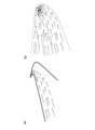
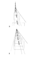
ここで、図11(a)では車両の高さを考慮していなかったが、実際には、図12-13のようになる。図12(a)は道路が直線の場合、図12(b)は道路が右にカーブしている場合、図13(a)は道路が左にカーブしている場合、図13(b)は道路が左にカーブしているが、カメラの位置がその道路を通るすべての車両の車高よりも高い位置にセットされている場合である。これらの図では、車両の大きさ(特に車高)を一定にして描いているが、実際には様々な車高の車両があるため、矢印は様々なy座標において出現する。例えば、図12(a)、(b)及び図13(b)の場合、図11(a)と同様に流れ場解析を行い特異点を求めることが可能であるが、図13(a)の場合、図11(b)のように関心領域の完全に内部に特異点があるため、通常の流れ場解析を適用して特異点を求めることができない。そこで、本発明では、図14に示すように、画像のx,y軸に加え、移動物体の面積Aを新たな軸に加えて3次元空間(x,y,A)とし、この3次元空間において、移動方向ベクトルに加え移動物体の面積の変化量dAを加えた3次元ベクトル(bx,by,dA)による流れ場を考える。図14から分かるように、このように移動物体の面積という新たな軸を加えた空間を考えることにより、特異点が関心領域の端点に来るようにでき、通常の流れ場解析を適用して特異点を推定することが可能になる。 Here, although the height of the vehicle was not taken into consideration in FIG. 11(a), it actually becomes as shown in FIGS. 12-13. Fig. 12(a) shows the case where the road is straight, Fig. 12(b) shows the case where the road curves to the right, Fig. 13(a) shows the case where the road curves to the left, Fig. 13(b) shows If the road curves to the left, but the camera position is set higher than the height of all vehicles on that road. In these figures, the size of the vehicle (especially the vehicle height) is fixed, but in reality there are vehicles with various vehicle heights, so the arrows appear at various y-coordinates. For example, in the case of FIGS. 12(a), (b), and 13(b), it is possible to obtain a singular point by performing flow field analysis in the same manner as in FIG. 11(a). In this case, as shown in FIG. 11(b), there is a singular point completely inside the region of interest, so the singular point cannot be obtained by applying a normal flow field analysis. Therefore, in the present invention, as shown in FIG. 14, in addition to the x and y axes of the image, the area A of the moving object is added to a new axis to form a three-dimensional space (x, y, A). Consider a flow field by a three-dimensional vector (b x , b y , dA) obtained by adding a change amount dA in the area of the moving object in addition to the moving direction vector. As can be seen from FIG. 14, by considering the space to which the area of the moving object is added as a new axis, the singular point can be positioned at the end point of the region of interest. It becomes possible to estimate points.
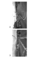
図9に、本実施形態の画像処理部の処理により特定した特異点を符号Pの点で示し、従来の透視図法で定義される消失点を、符号Qの点で示す。(a)のように遠方まで直線的な道路では差が小さいが、(b)のように途中で曲がった道路の場合には、特に、本実施形態の画像処理部による処理により特定された特異点が、従来の透視図法で定義される消失点と比べて、実際の移動物体の出現と消失位置により近い位置となっていることが明らかである。 In FIG. 9, the peculiar point specified by the processing of the image processing unit of the present embodiment is indicated by P, and the vanishing point defined by the conventional perspective drawing method is indicated by Q. Although the difference is small on a road that is straight to a long distance as in (a), in the case of a road that curves along the way as in (b), the peculiar It is clear that the points are located closer to the actual appearance and disappearance positions of the moving object than the vanishing points defined by the conventional perspective drawing method.
通常、特異点は遠方にあるため、そこから車両が出現したとしても背景からの変化はわずかであり、ほぼノイズレベルである。交通誘導員であっても、車両が出現した瞬間にそれを認識することは不可能であるが、その後の規則的な動きで接近車両の出現を認識している。本実施形態の画像処理部は、この思想を踏襲し、数フレームにわたり移動物体の動きを追跡する。これにより、仮に、1枚の静止画でノイズの中から車両を検知できる確率が0.1=10%(0.9=90%はノイズ)であったしても、たとえば1秒間、すなわち30フレームを利用することにより、30フレームとも雑音である確率は(1-0.1)30となるので、車両を検知できる確率は1-(1-0.1)30=0.96=96%となる。この結果、車両を容易に検知することが可能になった。 Normally, the singular point is far away, so even if a vehicle appears from there, the change from the background is slight and is almost at the noise level. Even the traffic director cannot recognize the appearance of the vehicle at the moment of its appearance, but recognizes the appearance of the approaching vehicle by its regular movement thereafter. The image processing unit of this embodiment follows this idea and tracks the movement of a moving object over several frames. As a result, even if the probability that a vehicle can be detected from noise in one still image is 0.1=10% (0.9=90% is noise), for example, one second, that is, 30% By using frames, the probability that all 30 frames are noise is (1-0.1) 30 , so the probability that a vehicle can be detected is 1-(1-0.1) 30 =0.96=96%. becomes. As a result, it became possible to easily detect the vehicle.
画像処理部の具体的な方法は以下のとおりである。車両が最初に出現する領域(画像の座標の集合)A0、その次のフレームでその車両の位置する領域A1,・・・nフレーム後での領域Anは、統計処理によって2値画像IFO(x,y,t)が求められている。そして、画像処理部は、

特異点付近で車両が検出された後は、カルマンフィルタ(Kalman Filter)により車両を追跡し、各フレームでの座標を推定することができる。画像処理部への実装にはMatlab(Motion-Based Multiple Object Tracking. Mathworks社製)を利用することができる。各フレームでの座標からカメラ座標と実座標を変換する幾何変換により停止線までの距離、速度、加速度のデータを得ることができる。画像処理部が追跡した車両の図面代用写真を、図10に示す。画像処理部は、図10中の矩形で示した部分を、車両と認識して追跡している。 After the vehicle is detected near the singularity, the vehicle can be tracked by a Kalman Filter and the coordinates at each frame can be estimated. Matlab (Motion-Based Multiple Object Tracking, manufactured by Mathworks) can be used for implementation in the image processing unit. The distance, velocity, and acceleration data to the stop line can be obtained by geometric transformation that converts the camera coordinates and the real coordinates from the coordinates in each frame. FIG. 10 shows a drawing substituting photograph of the vehicle tracked by the image processing unit. The image processing unit recognizes the portion indicated by the rectangle in FIG. 10 as a vehicle and tracks it.
本実施形態の画像処理部の車両早期検知能力、すなわちいかに早く接近車両を検知できるかを、物体形状認識と検出にしばしば利用される畳み込みニューラルネットワーク(R-CNN)を用いた手法と比較した。実装にはMatlabを利用した。畳み込みニューラルネットワークは、画像入力層、畳み込みニューラルネットワークの2D畳み込み層、正規化線形ユニット(ReLU)層、最大プーリング層、完全接続層、Softmax層、および分類出力層から形成されるネットワークである。畳み込みニューラルネットワークは、50,000個のトレーニング画像を含むCIFAR-10データセットを使用して学習させたものを利用した。これらのトレーニング画像には、自動車を含む10のカテゴリがあり、これらの物体の検出が可能である。学習には、初期学習率0.001の確率的勾配降下法(SGDM)を使用し、初期学習率は8エポックごとに減少させ、合計40エポックまで学習を行った。畳み込みニューラルネットワークがCIFAR-10データセットに対して適切に機能していることを確認した後、本実施形態で収集した動画像に対して追加で学習を行った。学習には、同じ確率的勾配降下法(SGDM)を使用し、初期学習率0.001とし、100エポックまで学習を行った。 The early vehicle detection capability of the image processing unit of this embodiment, ie, how quickly an approaching vehicle can be detected, was compared with a method using a convolutional neural network (R-CNN), which is often used for object shape recognition and detection. Matlab was used for implementation. A convolutional neural network is a network formed from an image input layer, a 2D convolutional layer of the convolutional neural network, a rectified linear unit (ReLU) layer, a max pooling layer, a fully connected layer, a Softmax layer, and a classification output layer. A convolutional neural network was utilized that was trained using the CIFAR-10 dataset containing 50,000 training images. These training images have 10 categories, including cars, and detection of these objects is possible. For learning, stochastic gradient descent (SGDM) with an initial learning rate of 0.001 was used, and the initial learning rate was decreased every 8 epochs, and learning was performed up to a total of 40 epochs. After confirming that the convolutional neural network worked well on the CIFAR-10 dataset, we additionally trained it on the video images collected in this embodiment. For training, the same stochastic gradient descent method (SGDM) was used with an initial learning rate of 0.001 and training was performed for 100 epochs.
本実施形態の画像処理部による処理と、畳み込みニューラルネットワークを用いた手法により、本実施形態のカメラで収集した動画像に対して、接近車両を検知する検証実験を行った。4例について、映像を逆回しして車両が検知しているフレームを肉眼により慎重に割り出したもの(真の出現フレーム番号)、停止線に至った点でのフレーム番号、画像処理部により最初に車両を検出したフレーム番号、畳み込みニューラルネットワークで最初に車両を検出したフレーム番号を表1に示す。本実施形態の画像処理部は、いずれも、真の出現時点から4~7フレーム後(0.23s以内)には車両を検出できた。また、畳み込みニューラルネットワークに比べて11~91フレーム(平均2s)早く検出できていることが明らかとなった。くりかえし実証実験を行った結果、定性的に表1と同様の結果が得られた。 A verification experiment for detecting an approaching vehicle was performed on moving images collected by the camera of the present embodiment, using processing by the image processing unit of the present embodiment and a technique using a convolutional neural network. For the four cases, the video was reversed and the frame detected by the vehicle was carefully determined by the naked eye (true appearance frame number), the frame number at the point where the stop line was reached, and the image processing unit first Table 1 shows the frame number in which the vehicle was detected and the frame number in which the convolutional neural network first detected the vehicle. All of the image processing units of this embodiment were able to detect the vehicle within 4 to 7 frames (within 0.23 seconds) after the true appearance point. In addition, it was found that the detection is faster by 11 to 91 frames (2 seconds on average) compared to the convolutional neural network. As a result of repeated demonstration experiments, qualitative results similar to those in Table 1 were obtained.

以上説明した画像処理部による画像処理により、制御用コンピュータは、第一のカメラ2aと第二のカメラ2bの画像を用いて、遠距離から近づいてくる車両Cの走行状態をデータとして抽出することができる。抽出された車両Cの走行状態のデータは、交通シュミレータが提供するデータと同等の走行に関するデータを含んでおり、この走行状態のデータを用いて、制御プログラムは、信号機3,4を適切に制御することができる。
By the image processing by the image processing section described above, the control computer uses the images of the
本実施形態の片側交互通行の制御システムの制御用コンピュータは、制御用プログラムと画像処理部を備えることにより、従来よりも遠方から片側交互通行区間に近づいてくる車両を識別することが可能となる。遠方からの車両を識別することで、各車両の走行状態がより正確に把握され、一層効率の良い片側交互通行の制御が可能となる。 The control computer of the alternate one-way traffic control system of this embodiment is equipped with a control program and an image processing unit, making it possible to identify vehicles approaching the alternate one-way traffic section from a farther distance than in the past. . By identifying vehicles from a distance, the running conditions of each vehicle can be grasped more accurately, and more efficient one-way alternate traffic control becomes possible.
本実施形態の交通信号機は、制御システムの制御プログラムによる制御によって、安全かつ効率よく車両の片側交互通行を実行するように、適切な信号の切り替えを行うことができる The traffic signal of this embodiment can perform appropriate signal switching so that vehicles can safely and efficiently perform one-way alternate traffic under the control of the control program of the control system.
1 制御用コンピュータ
2a 第一のカメラ
2b 第二のカメラ
2c 第三のカメラ
3,4 信号機
c 車両
P 特異点
Q 従来技術の消失点
1
Claims (5)
一方の車線の遠方から停止位置までを撮影する第一のカメラと、
他方の車線の遠方から停止位置までを撮影する第二のカメラと、
前記第一のカメラと前記第二のカメラが撮影した画像を用いてそれぞれの車線における車両の状態を取得し、信号機の判断ロジックを制御する制御用コンピュータと、
を、備えており、
前記制御用コンピュータが、少なくとも、片側交互通行区間を通過する単位時間あたりの車両の通行台数を正の報酬とし、かつ停止位置で停車する車両の平均停車時間を負の報酬として、その報酬が最大となる判断ロジックを学習した制御プログラムを記憶していることを特徴とする片側交互通行の制御システム。 A control system for alternating one-way traffic,
a first camera that captures one lane from a distance to a stop position;
a second camera that captures an image of the other lane from a distance to the stop position;
A control computer that acquires the state of the vehicle in each lane using the images captured by the first camera and the second camera, and controls the judgment logic of the traffic light;
, and
The control computer treats at least the number of vehicles passing through the one-way alternate traffic section per unit time as a positive reward and the average stop time of vehicles stopping at a stop position as a negative reward, and the reward is the maximum. A control system for alternating one-way traffic, characterized in that it stores a control program that learns the judgment logic to be.
前記画像処理部は、車両の特異点から規則的に移動する物体を車両として抽出する処理を行うことを特徴とする請求項1または2に記載の片側交互通行の制御システム。 The control computer includes an image processing unit that extracts a vehicle existing in the distance using an image captured by the first camera or the second camera,
3. The control system for alternating one-way traffic according to claim 1, wherein the image processing unit performs processing for extracting, as a vehicle, an object that moves regularly from a singular point of the vehicle.
それぞれの車線に配置される一対の信号機と、
一方の車線の遠方から停止位置までを撮影する第一のカメラと他方の車線の遠方から停止位置までを撮影する第二のカメラが撮影した画像を用いて、それぞれの車線における車両の状態を取得し、前記信号機の判断ロジックを制御する制御用コンピュータと、
を、備えており、
前記制御用コンピュータが、少なくとも、片側交互通行区間を通行する単位時間あたりの車両の通行台数を正の報酬とし、かつ停止位置で停車する車両の平均停車時間を負の報酬として、その報酬が最大となる判断ロジックを学習した制御プログラムを記憶しており、
前記一対の信号機は、前記制御プログラムによって、その表示内容と表示時間を変更することを特徴とする片側交互通行の交通信号機。 A traffic signal for alternating one-way traffic,
a pair of traffic lights arranged in each lane;
Using the images taken by the first camera, which captures the distance from one lane to the stop position, and the second camera, which captures the distance from the other lane to the stop position, the state of the vehicle in each lane is acquired. and a control computer that controls the decision logic of the traffic light;
, and
The control computer treats at least the number of passing vehicles per unit time passing through the one-way alternate traffic section as a positive reward and the average stop time of vehicles stopping at a stop position as a negative reward, and the reward is the maximum. It stores a control program that learns the judgment logic that becomes
A traffic signal for alternating one-way traffic, wherein the pair of traffic signals change their display contents and display time according to the control program.
Priority Applications (1)
| Application Number | Priority Date | Filing Date | Title |
|---|---|---|---|
| JP2021140919A JP7511822B2 (en) | 2021-08-31 | 2021-08-31 | One-way traffic control system |
Applications Claiming Priority (1)
| Application Number | Priority Date | Filing Date | Title |
|---|---|---|---|
| JP2021140919A JP7511822B2 (en) | 2021-08-31 | 2021-08-31 | One-way traffic control system |
Publications (2)
| Publication Number | Publication Date |
|---|---|
| JP2023034603A true JP2023034603A (en) | 2023-03-13 |
| JP7511822B2 JP7511822B2 (en) | 2024-07-08 |
Family
ID=85503965
Family Applications (1)
| Application Number | Title | Priority Date | Filing Date |
|---|---|---|---|
| JP2021140919A Active JP7511822B2 (en) | 2021-08-31 | 2021-08-31 | One-way traffic control system |
Country Status (1)
| Country | Link |
|---|---|
| JP (1) | JP7511822B2 (en) |
Cited By (2)
| Publication number | Priority date | Publication date | Assignee | Title |
|---|---|---|---|---|
| CN118334890A (en) * | 2024-05-24 | 2024-07-12 | 安徽江淮汽车集团股份有限公司 | A vehicle alternating traffic guidance system and method |
| CN119314343A (en) * | 2024-12-17 | 2025-01-14 | 武汉理工大学 | Intelligent two-way single lane reconstruction and expansion signal control method and system |
Citations (5)
| Publication number | Priority date | Publication date | Assignee | Title |
|---|---|---|---|---|
| JPH06265330A (en) * | 1993-03-11 | 1994-09-20 | N T T Data Tsushin Kk | Image measuring apparatus |
| JPH09231497A (en) * | 1996-02-23 | 1997-09-05 | Nippon Samikon Kk | Signal device for one-way traffic |
| JP2005267331A (en) * | 2004-03-19 | 2005-09-29 | Nissan Motor Co Ltd | Vehicle perimeter monitoring device |
| JP2013196519A (en) * | 2012-03-21 | 2013-09-30 | Toyota Central R&D Labs Inc | Object identification device and program |
| JP2017016554A (en) * | 2015-07-06 | 2017-01-19 | 株式会社日立製作所 | Traffic light control system and traffic light control method |
-
2021
- 2021-08-31 JP JP2021140919A patent/JP7511822B2/en active Active
Patent Citations (5)
| Publication number | Priority date | Publication date | Assignee | Title |
|---|---|---|---|---|
| JPH06265330A (en) * | 1993-03-11 | 1994-09-20 | N T T Data Tsushin Kk | Image measuring apparatus |
| JPH09231497A (en) * | 1996-02-23 | 1997-09-05 | Nippon Samikon Kk | Signal device for one-way traffic |
| JP2005267331A (en) * | 2004-03-19 | 2005-09-29 | Nissan Motor Co Ltd | Vehicle perimeter monitoring device |
| JP2013196519A (en) * | 2012-03-21 | 2013-09-30 | Toyota Central R&D Labs Inc | Object identification device and program |
| JP2017016554A (en) * | 2015-07-06 | 2017-01-19 | 株式会社日立製作所 | Traffic light control system and traffic light control method |
Cited By (2)
| Publication number | Priority date | Publication date | Assignee | Title |
|---|---|---|---|---|
| CN118334890A (en) * | 2024-05-24 | 2024-07-12 | 安徽江淮汽车集团股份有限公司 | A vehicle alternating traffic guidance system and method |
| CN119314343A (en) * | 2024-12-17 | 2025-01-14 | 武汉理工大学 | Intelligent two-way single lane reconstruction and expansion signal control method and system |
Also Published As
| Publication number | Publication date |
|---|---|
| JP7511822B2 (en) | 2024-07-08 |
Similar Documents
| Publication | Publication Date | Title |
|---|---|---|
| CN112101175B (en) | Expressway vehicle detection and multi-attribute feature extraction method based on local image | |
| CN113255520B (en) | Vehicle obstacle avoidance method based on binocular vision and deep learning and electronic equipment | |
| US10522039B2 (en) | Pedestrian recognition apparatus and method | |
| CN102214309B (en) | Special human body recognition method based on head and shoulder model | |
| Raja et al. | SPAS: Smart pothole-avoidance strategy for autonomous vehicles | |
| CN102930719B (en) | Video image foreground detection method for traffic intersection scene and based on network physical system | |
| CN106599832A (en) | Method for detecting and recognizing various types of obstacles based on convolution neural network | |
| CN112698653A (en) | Robot autonomous navigation control method and system based on deep learning | |
| CN112249021B (en) | A road pedestrian collision risk prediction method and system | |
| CN112721950A (en) | Autonomous vehicle control method and system based on deep learning | |
| Amanatiadis et al. | ViPED: On-road vehicle passenger detection for autonomous vehicles | |
| JP7511822B2 (en) | One-way traffic control system | |
| CN104778676A (en) | Depth ranging-based moving target detection method and system | |
| KR20210060535A (en) | Analysis of dynamic spatial scenarios | |
| CN105893963A (en) | Method for screening out optimal easily-recognizable frame of single pedestrian target in video | |
| CN117141470A (en) | A moral decision-making system for autonomous vehicles in complex collision scenarios | |
| CN120356177A (en) | End-to-end automatic driving track evaluation method and system based on world model | |
| Manglik et al. | Future near-collision prediction from monocular video: Feasibility, dataset, and challenges | |
| CN108846344A (en) | A kind of pedestrian's posture multiple features INTELLIGENT IDENTIFICATION method merging deep learning | |
| CN115576329B (en) | Obstacle avoidance method of unmanned AGV based on computer vision | |
| Wang et al. | End-to-end driving simulation via angle branched network | |
| CN111062311A (en) | Pedestrian gesture recognition and interaction method based on depth-level separable convolutional network | |
| CN116721251A (en) | A 3D target detection method that fuses dense segmentation of lidar point clouds and images | |
| Kim et al. | Traffic Accident Detection Based on Ego Motion and Object Tracking | |
| CN118823121B (en) | Aircraft door posture detection method based on fuzzy fusion and automatic boarding bridge control method |
Legal Events
| Date | Code | Title | Description |
|---|---|---|---|
| A621 | Written request for application examination |
Free format text: JAPANESE INTERMEDIATE CODE: A621 Effective date: 20230127 |
|
| A977 | Report on retrieval |
Free format text: JAPANESE INTERMEDIATE CODE: A971007 Effective date: 20231024 |
|
| A131 | Notification of reasons for refusal |
Free format text: JAPANESE INTERMEDIATE CODE: A131 Effective date: 20231031 |
|
| A521 | Request for written amendment filed |
Free format text: JAPANESE INTERMEDIATE CODE: A523 Effective date: 20231222 |
|
| A131 | Notification of reasons for refusal |
Free format text: JAPANESE INTERMEDIATE CODE: A131 Effective date: 20240220 |
|
| A521 | Request for written amendment filed |
Free format text: JAPANESE INTERMEDIATE CODE: A523 Effective date: 20240321 |
|
| TRDD | Decision of grant or rejection written | ||
| A01 | Written decision to grant a patent or to grant a registration (utility model) |
Free format text: JAPANESE INTERMEDIATE CODE: A01 Effective date: 20240521 |
|
| A61 | First payment of annual fees (during grant procedure) |
Free format text: JAPANESE INTERMEDIATE CODE: A61 Effective date: 20240617 |