JP2023068942A - structures and kits - Google Patents
structures and kits Download PDFInfo
- Publication number
- JP2023068942A JP2023068942A JP2021180412A JP2021180412A JP2023068942A JP 2023068942 A JP2023068942 A JP 2023068942A JP 2021180412 A JP2021180412 A JP 2021180412A JP 2021180412 A JP2021180412 A JP 2021180412A JP 2023068942 A JP2023068942 A JP 2023068942A
- Authority
- JP
- Japan
- Prior art keywords
- soil
- planting
- planting surface
- seedling
- shape
- Prior art date
- Legal status (The legal status is an assumption and is not a legal conclusion. Google has not performed a legal analysis and makes no representation as to the accuracy of the status listed.)
- Granted
Links
Images


Classifications
-
- Y—GENERAL TAGGING OF NEW TECHNOLOGICAL DEVELOPMENTS; GENERAL TAGGING OF CROSS-SECTIONAL TECHNOLOGIES SPANNING OVER SEVERAL SECTIONS OF THE IPC; TECHNICAL SUBJECTS COVERED BY FORMER USPC CROSS-REFERENCE ART COLLECTIONS [XRACs] AND DIGESTS
- Y02—TECHNOLOGIES OR APPLICATIONS FOR MITIGATION OR ADAPTATION AGAINST CLIMATE CHANGE
- Y02A—TECHNOLOGIES FOR ADAPTATION TO CLIMATE CHANGE
- Y02A30/00—Adapting or protecting infrastructure or their operation
- Y02A30/24—Structural elements or technologies for improving thermal insulation
- Y02A30/254—Roof garden systems; Roof coverings with high solar reflectance
-
- Y—GENERAL TAGGING OF NEW TECHNOLOGICAL DEVELOPMENTS; GENERAL TAGGING OF CROSS-SECTIONAL TECHNOLOGIES SPANNING OVER SEVERAL SECTIONS OF THE IPC; TECHNICAL SUBJECTS COVERED BY FORMER USPC CROSS-REFERENCE ART COLLECTIONS [XRACs] AND DIGESTS
- Y02—TECHNOLOGIES OR APPLICATIONS FOR MITIGATION OR ADAPTATION AGAINST CLIMATE CHANGE
- Y02B—CLIMATE CHANGE MITIGATION TECHNOLOGIES RELATED TO BUILDINGS, e.g. HOUSING, HOUSE APPLIANCES OR RELATED END-USER APPLICATIONS
- Y02B80/00—Architectural or constructional elements improving the thermal performance of buildings
- Y02B80/32—Roof garden systems
Landscapes
- Cultivation Of Plants (AREA)
- Cultivation Receptacles Or Flower-Pots, Or Pots For Seedlings (AREA)
Abstract
【課題】立体的な緑地を造形するための構造体を提供すること。【解決手段】本発明の一態様によれば、立体的な緑地を造形するための構造体が提供される。この構造体は、植栽部を備える。植栽部は、植栽面と、土壌保持部とを含む。植栽面は、植物を植栽可能に構成され、且つその裏面に連通する連通孔を備える。土壌保持部は、植栽面によって形状が規定される空間であり、且つ土壌を任意の三次元形状に造形した状態で保持する。連通孔と、土壌保持部とは、空間的に連続している。【選択図】図1An object of the present invention is to provide a structure for forming a three-dimensional green space. A structure for shaping a three-dimensional green space is provided according to one aspect of the present invention. This structure has a planting section. The planting section includes a planting surface and a soil holding section. The planting surface is configured to allow plants to be planted, and has communication holes communicating with the rear surface thereof. The soil holding part is a space whose shape is defined by the planting surface, and holds the soil in an arbitrary three-dimensional shape. The communication hole and the soil holding portion are spatially continuous. [Selection drawing] Fig. 1
Description
本発明は、構造体及びキットに関する。 The present invention relates to constructs and kits.
地面を緑化するための構造体が知られている。特許文献1には、格子状の形状を有する芝生保護材が開示されている。
Structures for greening the ground are known.
しかしながら、特許文献1に記載の従来技術では、三次元状に隆起した土壌を緑化することはできず、設計可能な緑地の形状に制限があった。
However, in the prior art described in
本発明では上記事情に鑑み、立体的な緑地を造形するための構造体を提供することとした。 In view of the above circumstances, the present invention provides a structure for forming a three-dimensional green space.
本発明の一態様によれば、立体的な緑地を造形するための構造体が提供される。この構造体は、植栽部を備える。植栽部は、植栽面と、土壌保持部とを含む。植栽面は、植物を植栽可能に構成され、且つその裏面に連通する連通孔を備える。土壌保持部は、植栽面によって形状が規定される空間であり、且つ土壌を任意の三次元形状に造形した状態で保持する。連通孔と、土壌保持部とは、空間的に連続している。 According to one aspect of the present invention, a structure for shaping a three-dimensional green space is provided. This structure has a planting section. The planting section includes a planting surface and a soil holding section. The planting surface is configured to allow plants to be planted, and has communication holes communicating with the back surface thereof. The soil holding part is a space whose shape is defined by the planting surface, and holds the soil in an arbitrary three-dimensional shape. The communication hole and the soil holding portion are spatially continuous.
このような態様によれば、立体的な緑地を造形するための構造体を提供することができる。 According to such an aspect, it is possible to provide a structure for shaping a three-dimensional green space.
以下、図面を用いて本開示の実施形態について説明する。以下に示す実施形態中で示した各種特徴事項は、互いに組み合わせ可能である。以下、構造体1及びキット2を使用する者のことを使用者という。使用者は、趣味で自宅の庭を造園する者であってもよく、公園、歩道、屋上庭園、テーマパーク、ゴルフ場、個人宅の庭等の造園を請け負う設計者又は土木作業者であってもよい。
Embodiments of the present disclosure will be described below with reference to the drawings. Various features shown in the embodiments shown below can be combined with each other. A person who uses the
1.第1の実施形態
以下、第1の実施形態である構造体1について詳述する。
1. First Embodiment Hereinafter, the
<構造体1の構成>
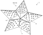
第1の実施形態は、立体的な緑地を造形するための構造体1である。図1及び図2は、第1の実施形態である構造体1の全体像を示す斜視図である。図1及び図2に示すとおり、構造体1は、植栽部10と、補強部14とを備える。植栽部10は、具体的には、凸部10a及び凹部10bを有する立体的な構造であってよい。補強部14は、具体的には、植栽部10の凹部10bに位置する、板状又は支柱状の構造であってよい。なお、補強部14は必須の構成ではない。
<Configuration of
1st Embodiment is the
植栽部10は、植栽面11と、土壌保持部13とを含む。植栽面11は、その裏面に連通する連通孔12を備える。植栽面11は、具体的には、植栽部10の凸部10aに延在する面であってよい。植栽面11は、植物の生育方向又は植物の根の成長方向(以下、生育方向等という)と略直交する面であってよい。具体的には例えば、生育方向等と植栽面11とのなす角が、60,65,70,75,80,85,90,95,100,105,110,115,120°であり、ここで例示した数値の何れか2つの間の範囲内であってもよい。
The
構造体1は、図1に示す側、すなわち植栽面11の側を上向きとして、地面の上に設置されてよい。好ましくは、構造体1が地面の上に設置される際、植栽面11の端部は地表面に接するように構成される。より好ましくは、植栽面11の端部及び補強部14の端部が地表面に接するように構成される。このような態様により、構造体1が地面に設置された際の安定性が向上する。
The
土壌保持部13は、植栽面11によって形状が規定される空間Sである。具体的には、土壌保持部13は、植栽面11の裏面側、すなわち植栽部10の凹部10bに存在する空間Sであってよい。植栽面11における連通孔12と、土壌保持部13とは、空間的に連続している。この態様によれば、連通孔12を通じて土壌21(後述の図3参照)中に外界から酸素を供給することができる。また、植栽面11に設置された植物が、連通孔12を通じて土壌21に根を張ることができる。すなわち、植物の生育が可能な構造体1を提供することができる。
The
<構造体1の形状>
構造体1は、任意の形状に土壌を保持し、立体的な緑地を造形するために用いることができる。一例として図1及び図2に示す構造体1では、立体的な星型形状に隆起した緑地の造形が可能である。
<Shape of
The
植栽部10における植栽面11は、植物を植栽可能に構成される。具体的には、植栽面11は、任意の三次元形状の広がりを有し、植物を植栽可能に構成される面である。例えば、植栽面11は、平面、曲面、又はそれらの組み合わせを含む形状であってよい。図1では、一例として、平面を組み合わせて星型形状に形成された植栽面11を示しているが、製造上実現可能な形状であれば、植栽面11の形状に制限はない。植栽面11は、例えば、ハート、星、スペード、植物、動物、人物若しくはキャラクター等をモチーフにした形状、円形、楕円形若しくは多角形等の幾何学的形状、文字若しくは数字を表した形状、又はこれらを組み合わせた形状であってよい。
A
植栽面11への植物の植栽は、植生基材で植栽面11を覆うことによって行われてもよい。植生基材は、一般的な土木工事に用いられるものであってよく、例えば、土、基盤材、接合材、肥料、水、植物の種子等から選択される材料の混合物であってよい。植物の植栽は、これらの材料を植栽面11に吹き付けることによって行われてもよく、これらの材料が装着されたシート又はマットを植栽面11上に貼り付けることによって行われてもよい。
The planting of plants on the
植栽面11に植栽される植物は、園芸用の草花であれば特に制限はないが、緑地の手入れの容易さという観点から、多年草であることが好ましい。より好ましくは、耐久性がある植物であるという観点から、植栽面11に植栽される植物は、芝苗22である。さらに好ましくは、植栽作業を容易に行うことができるという観点から、芝苗22は、シート状又はロール状の基材に植栽された状態で市場において取引される芝苗22である。芝の品種は、日本芝であっても西洋芝であってもよく、特に制限はない。シート上又はロール状の芝苗22は、植栽面11の表面に沿うように貼り付けられ、目串で固定されることによって植栽されてよい。
Plants to be planted on the
植栽面11の厚みは、構造体1の運搬時及び設置時に必要な強度を担保し、且つ植物の生育を抑制しない観点から、1mm以上50mm以下であることが好ましい。具体的には例えば、植栽面11の厚みは、1,2,3,4,5,6,7,8,9,10,11,12,13,14,15,16,17,18,19,20,21,22,23,24,25,26,27,28,29,30,31,32,33,34,35,36,37,38,39,40,41,42,43,44,45,46,47,48,49,50mmであり、ここで例示した数値の何れか2つの間の範囲内であってもよい。
The thickness of the
構造体1が地面に設置された際に、植栽面11の端部は、地表面と接することが好ましい。より好ましくは、構造体1は、植栽面11の端部に位置する不図示の差し込み部を有する。具体的には、差し込み部は、植栽面11の端部から延在する櫛歯であってよく、地中に挿入される。このような態様によれば、構造体1が地面に固定されるため、外力や風雨等による構造体1の移動を防ぐことができる。
When the
好ましくは、植栽面11は、不図示の凹凸構造をさらに有する。凹凸構造とは、例えば、リブ状、ワッフル状、シボ状、櫛歯状等の構造であってよい。また、凹凸構造は、植栽面11上において芝苗22を固定可能に構成されてよい。より好ましくは、凹凸構造は、植栽面11の表面から延在する櫛歯構造である。ここで櫛歯構造は、複数の櫛歯を有し、シート上又はロール状の芝苗22に櫛歯を挿通することで、芝苗22を固定可能に構成される。このような態様によれば、傾斜のある植栽面11において芝苗22のずれ落ちを抑制することができ、使用者は、意図した位置に芝苗22を設置することが可能となる。すなわち、使用者の意図した通りに芝苗22が植栽された、外観の美しい緑地を造形可能な構造体1を提供することができる。
Preferably, the
凹凸構造の高さ、すなわち凹凸構造の高低差は、植物が根付きやすい構造を実現し、製造コストを抑制する観点から、具体的には例えば、0.1,0.2,0.3,0.4,0.5,0.6,0.7,0.8,0.9,1,2,3,4,5,6,7,8,9,10,11,12,13,14,15,16,17,18,19,20,21,22,23,24,25,26,27,28,29,30mmであり、ここで例示した数値の何れか2つの間の範囲内であってもよい。 The height of the uneven structure, that is, the height difference of the uneven structure, is specifically, for example, 0.1, 0.2, 0.3, 0, from the viewpoint of realizing a structure that allows plants to take root easily and suppressing manufacturing costs. .4, 0.5, 0.6, 0.7, 0.8, 0.9, 1, 2, 3, 4, 5, 6, 7, 8, 9, 10, 11, 12, 13, 14 , 15, 16, 17, 18, 19, 20, 21, 22, 23, 24, 25, 26, 27, 28, 29, 30 mm and within the range between any two of the values exemplified here There may be.
土壌保持部13、すなわち植栽面11によって形状が規定される空間Sは、土壌21(後述の図3参照)を任意の三次元形状に造形した状態で保持する。具体的には、空間Sは、植物が根を張るための土壌21を収容可能に構成される空間Sである。土壌保持部13が保持する土壌21は、園芸用の土壌であれば種類に制限はないが、植栽面11に植栽される植物の品種、及び緑化を実施する場所によって適切な土壌が使用されるのが好ましい。例えば、天然土壌、人工土壌等であってもよく、ビルの屋上緑化に使用される場合には、軽量人工土壌が使用されてよい。
The
連通孔12の形状は、特に制限はないが、例えば、円形状、多角形状、スリット状等であってよい。連通孔12の個数は、特に制限はないが、植物の生育環境を向上させる観点から、連通孔12は複数存在することが好ましい。より好ましくは、連通孔12の合計面積/植栽面11の面積の割合は、10%以上80%以下である。このような態様により、構造体1が土壌21を保持するための強度を担保し、且つ植物が土壌21に根を張ることが容易となる。具体的には、例えば、連通孔12の合計面積/植栽面11の面積の割合は、10,11,12,13,14,15,16,17,18,19,20,21,22,23,24,25,26,27,28,29,30,31,32,33,34,35,36,37,38,39,40,41,42,43,44,45,46,47,48,49,50,51,52,53,54,55,56,57,58,59,60,61,62,63,64,65,66,67,68,69,70,71,72,73,74,75,76,77,78,79,80%であり、ここで例示した数値の何れか2つの間の範囲内であってもよい。
The shape of the
補強部14は、植栽面11の裏側に位置し、形状を補強するように構成される。すなわち、好ましくは、構造体1は、補強部14をさらに有する。このような態様によれば、複雑な形状の植栽面11であっても、構造体1の強度を保つことができる。すなわち、より複雑な形状の緑地を造形することが可能な構造体1を提供することができる。補強部14は、植栽部10と一体であってもよく、別体であってもよい。補強部14は、例えば、複数の板状部材を含むリブ構造、複数の支柱及び梁を含む骨組み構造、又はこれらの組み合わせであってよい。補強部14が植栽部10と別体である場合には、補強部14及び植栽部10が係止部を有し、お互いを結合可能に構成されていてもよい。
The reinforcement part 14 is positioned on the back side of the
構造体1が地面に設置された際に、補強部14の端部は、地表面と接することが好ましい。より好ましくは、補強部14の端部は、地中に挿入される。このような態様によれば、補強部14の一部が地中に埋まった状態となり、構造体1が地面に固定されるため、外力や風雨等による構造体1の移動を防ぐことができる。
When the
好ましくは、補強部14は、植栽面11の裏側に位置するリブ構造を有する。具体的には、リブ構造は、植栽面11の裏面から延在する、複数の板状部材であってよい。複数の板状部材は、所定の間隔を空けて並列に配置されていてもよく、格子状に組み合わせられて配置されていてもよい。このような態様によれば、補強部14を有する構造体1を容易に製造することが可能となる。すなわち、製造コストが低く、より強度の高い構造体1を提供することができる。
Preferably, the reinforcement part 14 has a rib structure located on the back side of the
リブ構造の厚みは、植栽部10を補強し、且つ製造コストを抑制する観点から、0.3mm以上20mm以下であってよい。リブ構造の厚みは、具体的には例えば、0.3,0.4,0.5,0.6,0.7,0.8,0.9,1,2,3,4,5,6,7,8,9,10,11,12,13,14,15,16,17,18,19,20mmであり、ここで例示した数値の何れか2つの間の範囲内であってもよい。
The thickness of the rib structure may be 0.3 mm or more and 20 mm or less from the viewpoint of reinforcing the planted
好ましくは、補強部14は、植栽部10と別体であり、使用者によって組立てが可能に構成される。このような態様により、植栽部10及び補強部14を一体で製造可能な形状とするための設計上の制約がなくなり、使用者は、より自由な形状の緑地を造形することができる。より好ましくは、植栽部10は、補強部14の位置を決定するための溝、ガイド、側壁等を有する。このような態様により、使用者が容易に構造体1を組み立てることが可能となる。
Preferably, the reinforcing part 14 is separate from the
<構造体1の材質>
構造体1は、任意の方法で成形された成形体であってよい。成形の方法は、射出成形、プレス成形、ブロー成形、3Dプリンタによる成形等の方法が用いられてもよい。構造体1の材質としては、特に制限はないが、好ましくは、構造体1の材質は、生分解性材料を含む。このような態様によれば、構造体1の一部が土壌21中で分解されため、環境に与える負荷を低減することができる。より好ましくは、構造体1の材質は、生分解性材料である。このような態様によれば、構造体1は、設置された後に土壌21中で分解されるため、環境に与える負荷をより低減することができる。
<Material of
The
生分解性材料は、天然由来の原料、生分解性プラスチック等であってよい。天然由来の原料は、例えば、リグニン、セルロース、キトサン、リン酸カルシウム、澱粉、ゼラチン等の原料を使用して成形されてよい。具体的には、古紙、枯れ葉、枯れ枝、木材の廃材、農作物の食用でない部分、生物の骨、甲殻類の甲羅等を粉砕した原料に、澱粉のり等の天然由来の粘着剤を添加し、押し固めることによって任意の形状の構造体1が成形されてもよい。
The biodegradable material may be naturally derived raw materials, biodegradable plastics, and the like. Raw materials of natural origin may be formed using raw materials such as lignin, cellulose, chitosan, calcium phosphate, starch, gelatin, and the like. Specifically, waste paper, dead leaves, dead branches, wood scraps, inedible parts of agricultural products, bones of organisms, shells of crustaceans, etc. are crushed into raw materials. Arbitrary shaped
構造体1は、生分解性材料以外の素材を含んでもよい。例えば、プラスチック材料、材料の強度を向上させるための充填剤、材料の成形性を向上させるための添加剤、植物の生育を促進するための肥料、農薬等を含んでよい。
The
より好ましくは、生分解性材料は、生分解性プラスチックである。生分解性プラスチックは、例えば、ポリビニルアルコール(PVA)、ポリグリコール酸、澱粉ポリエステル等の変性澱粉、酢酸セルロース等の変性セルロース、脂肪族ポリエステル、芳香族ポリエステル、ポリヒドロキシアルカン酸(PHA)等から選択可能である。生分解性プラスチックは、1種又は複数種の組み合わせであってよい。このような態様によれば、設計の自由度が高く、製造が容易であり、使用後に土壌21中で分解可能な構造体1を提供することができる。すなわち、成形性と、環境に与える負荷の低減とを両立することができる。
More preferably, the biodegradable material is biodegradable plastic. Biodegradable plastics are selected from, for example, polyvinyl alcohol (PVA), polyglycolic acid, modified starch such as starch polyester, modified cellulose such as cellulose acetate, aliphatic polyester, aromatic polyester, polyhydroxyalkanoic acid (PHA), etc. It is possible. Biodegradable plastics may be one or a combination of more than one. According to this aspect, it is possible to provide the
脂肪族ポリエステルは、例えば、ポリ乳酸(PLA)、ポリブチレンサクシネート(PBS)、ポリブチレンサクシネート/アジペート(PBSA)、ポリカプロラクトン(PCL)、ポリブチレンサクシネート/カーボネイト(PEC)、ポリエチレンサクシネート(PES)、ポリエチレンサクシネート/アジペート、ポリ乳酸/ポリカプロラクトン共重合体、ポリ乳酸/ポリエーテル共重合体等であってよい。 Aliphatic polyesters are, for example, polylactic acid (PLA), polybutylene succinate (PBS), polybutylene succinate/adipate (PBSA), polycaprolactone (PCL), polybutylene succinate/carbonate (PEC), polyethylene succinate (PES), polyethylene succinate/adipate, polylactic acid/polycaprolactone copolymer, polylactic acid/polyether copolymer, and the like.
芳香族ポリエステルは、例えば、ポリブチレンアジペート/テレフタレート(PBAT)、ポリテトラメチレンアジペート/テレフタレート、ポリエチレンテレフタレート/サクシネート(CPE)等であってよい。 Aromatic polyesters can be, for example, polybutylene adipate/terephthalate (PBAT), polytetramethylene adipate/terephthalate, polyethylene terephthalate/succinate (CPE), and the like.
ポリヒドロキシアルカン酸(PHA)は、例えば、ポリ-3-ヒドロキシ酪酸(PHB)、ポリ(3-ヒドロキシブチレート/3-ヒドロキシバレレート)(PHBV)、ポリ(3-ヒドロキシブチレート/3-ヒドロキシヘキサノエート)(PHBH)、ポリ(3-ヒドロキシブチレート/4-ヒドロキシブチレート)等であってよい。 Polyhydroxyalkanoic acids (PHA) are, for example, poly-3-hydroxybutyric acid (PHB), poly(3-hydroxybutyrate/3-hydroxyvalerate) (PHBV), poly(3-hydroxybutyrate/3-hydroxy hexanoate) (PHBH), poly(3-hydroxybutyrate/4-hydroxybutyrate), and the like.
補強部14が植栽部10と別体である場合には、補強部14は、金属、木材等の材料で形成された部材を含んでいてもよい。好ましくは、補強部14の強度を向上させる観点から、金属製の部材を含むことが好ましい。金属製の部材は、例えば、金属パイプであってよい。
When the reinforcing portion 14 is separate from the
2.第2の実施形態(キット)
以下、第2の実施形態であるキット2について詳述する。前節で既に説明した構造体1の態様は、本節でも同様のため省略する。
2. Second embodiment (kit)
The
<キット2の構成>
第2の実施形態は、緑地を造形するためのキット2である。図3は、図1におけるA-A断面図を用いて、第2の実施形態であるキット2を説明するための図である。図3に示すように、キット2は、構造体1と、芝苗22と、土壌21とを備える。芝苗22及び土壌21の好ましい態様は、前節に記載の内容と同様のため省略する。ここで芝苗22は、植栽面11の表面に位置するように植栽され、土壌21は、土壌保持部13の内部に位置するように構成される。このような態様によれば、使用者は、芝苗22と土壌21を自分で準備する必要がなくなり、容易に所望の形状の緑地を造形することができる。すなわち、使用者の利便性が向上する。
<Composition of
A second embodiment is a
好ましくは、キット2は、土壌21を収容する不図示の土壌袋をさらに有していてもよい。具体的には、土壌袋は、土壌21を包んだ状態で土壌保持部13に収容されてよい。このような態様によれば、キット2の流通時に土壌21が土壌保持部13から漏れ出てしまうことを防ぐことができる。土壌袋は、不織布等の布帛であってもよく、ネットであってもよい。土壌袋の素材は、土壌21が漏れ出ない程度に目が細かいものであればよく、環境への負荷を低減する観点から、生分解性の素材であることが好ましい。
Preferably, the
好ましくは、キット2は、不図示の目串をさらに備える。ここで、目串は、連通孔12を介して、芝苗22と土壌21とを固定可能に構成される。具体的には、目串は、芝苗22が植栽されたシート状又はロール状の基材を貫通し、連通孔12を介して、土壌21に挿入される。このような態様によれば、運搬中に芝苗22が植栽面11上からずれ落ちてしまうことや、設置後に風雨によって芝苗22が剥がれてしまうことを抑制することができる。
Preferably, the
より好ましくは、目串は、構造体1の成形の際に生じる端材である。例えば、構造体1が射出成形によって成形された場合、端材は、成形に係るランナー、ゲート、スプルー等であってよい。このような態様によれば、構造体1の成形の際に生じる端材を有効活用することができ、製造によるごみの量を減らすことができる。すなわち、環境への負荷をより低減したキット2を提供することができる。端材は、そのまま目串として用いられてもよく、所望の大きさに切り出す等の加工がなされてもよい。
More preferably, the crosspieces are offcuts generated when the
好ましくは、生分解性材料で成形された構造体1の端材は、粉砕され、土壌21に混合されてもよい。このような態様によれば、成形時に生じる端材を焼却処分することなく、全て有効活用することができるため、キット2の製造によって生じるごみの量を削減し、二酸化炭素の排出量を低減することができる。
Preferably, offcuts of the
3.変形例
前述の実施形態に係る構造体に関して、以下のような態様を採用してもよい。
3. Modifications Regarding the structure according to the above-described embodiment, the following aspects may be adopted.
図4は、変形例の全体像を示す斜視図である。図4に示すように、複数の構造体1を組み合わせることによって、立体的な緑地が造形されてもよい。図4では、例として、アルファベットのE字状の立体形状の緑地が造形された様子を示している。
FIG. 4 is a perspective view showing an overall image of a modification. As shown in FIG. 4, by combining a plurality of
図5は、図4中のB視点から変形例を見た様子を示した拡大図である。図5に示すように、構造体1は、連結部15をさらに有してもよい。連結部15は、他の構造体1における連結部15と、互いに連結可能に構成され、これにより構造体1どうしの連結を可能とする。このような態様によれば、使用者が、構造体1を組み合わせて、より大きな構造を造形することが可能となる。すなわち、使用者が所望する形状を容易に造形可能な構造体1を提供することができる。
FIG. 5 is an enlarged view showing a modified example viewed from a viewpoint B in FIG. As shown in FIG. 5 , the
図5に示すように、植栽面11は、外周を連結部15で囲まれた面であってよい。構造体1同士の連結を容易にする観点から、植栽面11は平面であってもよい。変形例において土壌保持部13は、複数の植栽面11によって形状が規定される空間Sである。
As shown in FIG. 5 , the
連結部15は、例えば、凹構造及び凸構造を有し、凹構造及び凸構造がお互いに係合するように構成されていてもよい。凹構造及び凸構造は、例えば、スナップフィット構造であってよい。連結部15は、例えば、ビスやリベット等の固定部材を介して複数の構造体1が連結されるように構成されていてもよい。
The
4.その他
実施形態では、土を盛って凸状の緑地を造形する場合について説明したが、穴を掘って凹状の緑地を造形してもよい。その場合、植栽面11は、植栽部10の凹部10bに延在する面であってよい。
4. Others In the embodiment, the case of forming a convex green space by piling up soil has been described, but a hole may be dug to form a concave green space. In that case, the
一態様において、植栽部10は、少なくとも一部が多孔質状であってよい。多孔質素材としては、例えば、活性炭、珪藻土、ゼオライト等の既知の素材が用いられてもよく、生分解性プラスチックの多孔質膜等が用いられてもよい。また、多孔質素材の空孔内に、植物の生育を促進させるための肥料、土壌改質剤、農薬等を含んでもよい。
In one aspect, at least a portion of the
さらに、次に記載の各態様で提供されてもよい。
前記構造体において、補強部をさらに有し、前記補強部は、前記植栽面の裏側に位置し、前記形状を補強するように構成される、もの。
前記構造体において、前記補強部は、前記植栽面の裏側に位置するリブ構造を有する、もの。
前記構造体において、連結部をさらに有し、前記連結部は、他の構造体における連結部と、互いに連結可能に構成され、これにより前記構造体どうしの連結を可能とする、もの。
前記構造体において、前記構造体の材質が、生分解性材料を含む、もの。
前記構造体において、前記生分解性材料は、生分解性プラスチックである、もの。
前記構造体において、前記植物は、芝苗であり、前記植栽面は、凹凸構造をさらに有し、ここで前記凹凸構造は、前記植栽面上において前記芝苗を固定可能に構成される、もの。
緑地を造形するためのキットであって、前記構造体と、芝苗と、土壌とを備え、前記芝苗は、前記植栽面の表面に位置するように植栽され、前記土壌は、前記土壌保持部の内部に位置するように構成される、もの。
前記キットにおいて、目串をさらに備え、前記構造体は、成形体であり、前記目串は、前記構造体の成形の際に生じる端材であり、且つ前記連通孔を介して、前記芝苗と前記土壌とを固定可能に構成される、もの。
もちろん、この限りではない。
Furthermore, it may be provided in each aspect described below.
The structure further includes a reinforcing portion, the reinforcing portion being located on the back side of the planting surface and configured to reinforce the shape.
In the structure, the reinforcing part has a rib structure located on the back side of the planting surface.
The structure further has a connecting part, and the connecting part is configured to be connectable with a connecting part of another structure, thereby enabling the structures to be connected to each other.
In the structure, the material of the structure contains a biodegradable material.
In the structure, the biodegradable material is biodegradable plastic.
In the structure, the plant is a lawn seedling, and the planting surface further has an uneven structure, wherein the uneven structure is configured to be capable of fixing the lawn seedling on the planting surface. ,thing.
A kit for shaping a green space, comprising the structure, a lawn seedling, and soil, the lawn seedling being planted so as to be positioned on the surface of the planting surface, and the soil being the A thing configured to be located inside a soil-retaining part.
The kit further comprises a skewer, wherein the structure is a molded body, the skewer is a scrap material generated when the structure is molded, and the grass seedling is inserted through the communication hole. and the soil can be fixed.
Of course, it is not limited to this.
最後に、本開示に係る種々の実施形態を説明したが、これらは、例として提示したものであり、発明の範囲を限定することは意図していない。当該新規な実施形態は、その他の様々な形態で実施されることが可能であり、発明の要旨を逸脱しない範囲で、種々の省略、置き換え、変更を行うことができる。当該実施形態やその変形は、発明の範囲や要旨に含まれるとともに、特許請求の範囲に記載された発明とその均等の範囲に含まれるものである。 Finally, while various embodiments of the present disclosure have been described, they have been presented by way of example and are not intended to limit the scope of the invention. The novel embodiment can be embodied in various other forms, and various omissions, replacements, and modifications can be made without departing from the scope of the invention. The embodiment and its modifications are included in the scope and gist of the invention, and are included in the scope of the invention described in the claims and equivalents thereof.
1 :構造体
10 :植栽部
10a :凸部
10b :凹部
11 :植栽面
12 :連通孔
13 :土壌保持部
14 :補強部
15 :連結部
2 :キット
21 :土壌
22 :芝苗
S :空間
Reference Signs List 1: structure 10:
Claims (9)
植栽部を備え、
前記植栽部は、植栽面と、土壌保持部とを含み、
前記植栽面は、植物を植栽可能に構成され、且つその裏面に連通する連通孔を備え、
前記土壌保持部は、前記植栽面によって形状が規定される空間であり、且つ土壌を任意の三次元形状に造形した状態で保持し、
前記連通孔と、前記土壌保持部とは、空間的に連続している、もの。 A structure for forming a three-dimensional green space,
Equipped with a planting section,
The planting section includes a planting surface and a soil holding section,
The planting surface is configured to allow plants to be planted, and has a communication hole communicating with the back surface,
The soil holding part is a space whose shape is defined by the planting surface, and holds the soil in an arbitrary three-dimensional shape,
The communication hole and the soil holding portion are spatially continuous.
補強部をさらに有し、
前記補強部は、前記植栽面の裏側に位置し、前記形状を補強するように構成される、もの。 The structure of claim 1, wherein
further having a reinforcing portion;
The reinforcing part is positioned on the back side of the planting surface and configured to reinforce the shape.
前記補強部は、前記植栽面の裏側に位置するリブ構造を有する、もの。 The structure of claim 2, wherein
The reinforcing part has a rib structure located on the back side of the planting surface.
連結部をさらに有し、
前記連結部は、他の構造体における連結部と、互いに連結可能に構成され、これにより前記構造体どうしの連結を可能とする、もの。 In the structure according to any one of claims 1 to 3,
further having a connecting portion;
The connecting portion is configured to be connectable with a connecting portion of another structure, thereby enabling the structures to be connected to each other.
前記構造体の材質が、生分解性材料を含む、もの。 In the structure according to any one of claims 1 to 4,
A material of the structure includes a biodegradable material.
前記生分解性材料は、生分解性プラスチックである、もの。 The structure of claim 5, wherein
The biodegradable material is biodegradable plastic.
前記植物は、芝苗であり、
前記植栽面は、凹凸構造をさらに有し、
ここで前記凹凸構造は、前記植栽面上において前記芝苗を固定可能に構成される、もの。 In the structure according to any one of claims 1 to 6,
The plant is a lawn seedling,
The planting surface further has an uneven structure,
Here, the concave-convex structure is configured to be capable of fixing the lawn seedling on the planting surface.
請求項1~請求項8の何れか1つに記載の構造体と、芝苗と、土壌とを備え、
前記芝苗は、前記植栽面の表面に位置するように植栽され、
前記土壌は、前記土壌保持部の内部に位置するように構成される、もの。 A kit for shaping a green area,
A structure comprising the structure according to any one of claims 1 to 8, a lawn seedling, and soil,
The lawn seedling is planted so as to be positioned on the surface of the planting surface,
The soil is configured to be located inside the soil holding portion.
目串をさらに備え、
前記構造体は、成形体であり、
前記目串は、前記構造体の成形の際に生じる端材であり、且つ前記連通孔を介して、前記芝苗と前記土壌とを固定可能に構成される、もの。 In the kit of claim 8,
Equipped with an eye skewer,
The structure is a molded body,
The crosspiece is a piece of material produced when the structure is molded, and is configured to be able to fix the grass seedling and the soil through the communication hole.
Priority Applications (2)
| Application Number | Priority Date | Filing Date | Title |
|---|---|---|---|
| JP2021180412A JP7023556B1 (en) | 2021-11-04 | 2021-11-04 | Structures and kits |
| JP2022015133A JP2023069992A (en) | 2021-11-04 | 2022-02-02 | Structure and kit |
Applications Claiming Priority (1)
| Application Number | Priority Date | Filing Date | Title |
|---|---|---|---|
| JP2021180412A JP7023556B1 (en) | 2021-11-04 | 2021-11-04 | Structures and kits |
Related Child Applications (1)
| Application Number | Title | Priority Date | Filing Date |
|---|---|---|---|
| JP2022015133A Division JP2023069992A (en) | 2021-11-04 | 2022-02-02 | Structure and kit |
Publications (2)
| Publication Number | Publication Date |
|---|---|
| JP7023556B1 JP7023556B1 (en) | 2022-02-22 |
| JP2023068942A true JP2023068942A (en) | 2023-05-18 |
Family
ID=81079696
Family Applications (2)
| Application Number | Title | Priority Date | Filing Date |
|---|---|---|---|
| JP2021180412A Active JP7023556B1 (en) | 2021-11-04 | 2021-11-04 | Structures and kits |
| JP2022015133A Pending JP2023069992A (en) | 2021-11-04 | 2022-02-02 | Structure and kit |
Family Applications After (1)
| Application Number | Title | Priority Date | Filing Date |
|---|---|---|---|
| JP2022015133A Pending JP2023069992A (en) | 2021-11-04 | 2022-02-02 | Structure and kit |
Country Status (1)
| Country | Link |
|---|---|
| JP (2) | JP7023556B1 (en) |
Cited By (1)
| Publication number | Priority date | Publication date | Assignee | Title |
|---|---|---|---|---|
| KR102847426B1 (en) * | 2024-11-01 | 2025-08-18 | 박영미 | Flower Grip and Method for Manufacturing the Same |
Citations (13)
| Publication number | Priority date | Publication date | Assignee | Title |
|---|---|---|---|---|
| US2113523A (en) * | 1937-08-18 | 1938-04-05 | White Stanley Hart | Vegetation-bearing architectonic structure and system |
| JPS4912963B1 (en) * | 1969-07-25 | 1974-03-28 | ||
| JPS51115142U (en) * | 1975-03-15 | 1976-09-18 | ||
| JPS63261069A (en) * | 1987-04-20 | 1988-10-27 | 株式会社 ドコ− | Structure having lawn |
| JPH01105435U (en) * | 1987-12-31 | 1989-07-17 | ||
| JP2001073376A (en) * | 1999-09-06 | 2001-03-21 | Ug Kizai Kk | Greening method for slope |
| JP2001231396A (en) * | 2000-02-24 | 2001-08-28 | Katsuumi Yoshimi | Concrete folded plate structure |
| EP1358791A2 (en) * | 2002-05-03 | 2003-11-05 | Smithers-Oasis Company | Topiary article and method of making the same |
| JP2006322209A (en) * | 2005-05-18 | 2006-11-30 | Taniyasu Sogyo:Kk | Earth retaining implement for seeding and planting slope face and slope face by seeding and planting |
| JP3137461U (en) * | 2007-09-14 | 2007-11-22 | 知洋 前田 | Turf ornaments |
| KR20120126288A (en) * | 2011-05-11 | 2012-11-21 | 주식회사 에코밸리 | A Column Type Artificial Rock Mountain For Providing a Natural Beauty and Method For Manufacturing Thereof |
| KR101449338B1 (en) * | 2013-10-29 | 2014-10-08 | 이상규 | Structure of grave with half ball type artificial turf plate and inner cover for burial mound, forming method for burial mound using the same |
| KR101875157B1 (en) * | 2016-06-29 | 2018-07-06 | 우재동 | Miniature Grave |
-
2021
- 2021-11-04 JP JP2021180412A patent/JP7023556B1/en active Active
-
2022
- 2022-02-02 JP JP2022015133A patent/JP2023069992A/en active Pending
Patent Citations (13)
| Publication number | Priority date | Publication date | Assignee | Title |
|---|---|---|---|---|
| US2113523A (en) * | 1937-08-18 | 1938-04-05 | White Stanley Hart | Vegetation-bearing architectonic structure and system |
| JPS4912963B1 (en) * | 1969-07-25 | 1974-03-28 | ||
| JPS51115142U (en) * | 1975-03-15 | 1976-09-18 | ||
| JPS63261069A (en) * | 1987-04-20 | 1988-10-27 | 株式会社 ドコ− | Structure having lawn |
| JPH01105435U (en) * | 1987-12-31 | 1989-07-17 | ||
| JP2001073376A (en) * | 1999-09-06 | 2001-03-21 | Ug Kizai Kk | Greening method for slope |
| JP2001231396A (en) * | 2000-02-24 | 2001-08-28 | Katsuumi Yoshimi | Concrete folded plate structure |
| EP1358791A2 (en) * | 2002-05-03 | 2003-11-05 | Smithers-Oasis Company | Topiary article and method of making the same |
| JP2006322209A (en) * | 2005-05-18 | 2006-11-30 | Taniyasu Sogyo:Kk | Earth retaining implement for seeding and planting slope face and slope face by seeding and planting |
| JP3137461U (en) * | 2007-09-14 | 2007-11-22 | 知洋 前田 | Turf ornaments |
| KR20120126288A (en) * | 2011-05-11 | 2012-11-21 | 주식회사 에코밸리 | A Column Type Artificial Rock Mountain For Providing a Natural Beauty and Method For Manufacturing Thereof |
| KR101449338B1 (en) * | 2013-10-29 | 2014-10-08 | 이상규 | Structure of grave with half ball type artificial turf plate and inner cover for burial mound, forming method for burial mound using the same |
| KR101875157B1 (en) * | 2016-06-29 | 2018-07-06 | 우재동 | Miniature Grave |
Cited By (1)
| Publication number | Priority date | Publication date | Assignee | Title |
|---|---|---|---|---|
| KR102847426B1 (en) * | 2024-11-01 | 2025-08-18 | 박영미 | Flower Grip and Method for Manufacturing the Same |
Also Published As
| Publication number | Publication date |
|---|---|
| JP7023556B1 (en) | 2022-02-22 |
| JP2023069992A (en) | 2023-05-18 |
Similar Documents
| Publication | Publication Date | Title |
|---|---|---|
| US5018300A (en) | Hanging basket liner | |
| US6658790B2 (en) | Method of propagation and product produced thereby | |
| WO2008037985A1 (en) | Biodegradable tree shelter with prolonged durability | |
| ZA200405440B (en) | A tree shelter | |
| AU2010345507B2 (en) | Vegetation element for greening artificial or natural surfaces having low and/or high plants and method for producing the vegetation element | |
| US20040111967A1 (en) | Preformed container for growing flowering plant bulbs | |
| JP7023556B1 (en) | Structures and kits | |
| US20100212560A1 (en) | Geomat | |
| CA2299083A1 (en) | Plant greenhouse frost protector and growth enhancer | |
| CN101647361A (en) | Cultivation method of elms | |
| US7036272B2 (en) | Plant container | |
| JP2002235323A (en) | Pile molded from biodegradable resin and sheet installation structure | |
| JP3806732B2 (en) | Plant growth container | |
| JP3156077B2 (en) | Mat growing tray and plant growing method | |
| KR20210061626A (en) | Weed proofing walking mat | |
| JP2004082657A (en) | Wood chip molding | |
| JP2009213372A (en) | Plant cultivation material, and method for producing dried bean curd refuse | |
| GB2483800A (en) | Elongate panels for forming planting containers | |
| JP2001204265A (en) | Biodegradable plastic seedling raising container, method for raising seedlings and greening method using the container | |
| KR100807122B1 (en) | Planting seedling mulching mat | |
| JP2002233251A (en) | Structure of container for rearing plant | |
| US20060185230A1 (en) | Vegetation barrier | |
| NL2007198C2 (en) | A plant tray for propagating plants, a tray, and methods. | |
| CN211745612U (en) | Flowerpot suitable for planting selaginella tamariscina | |
| CN211297876U (en) | Melon is planted and is used degradable non-woven fabrics plastic film |
Legal Events
| Date | Code | Title | Description |
|---|---|---|---|
| A621 | Written request for application examination |
Free format text: JAPANESE INTERMEDIATE CODE: A621 Effective date: 20211105 |
|
| A871 | Explanation of circumstances concerning accelerated examination |
Free format text: JAPANESE INTERMEDIATE CODE: A871 Effective date: 20211105 |
|
| A131 | Notification of reasons for refusal |
Free format text: JAPANESE INTERMEDIATE CODE: A131 Effective date: 20211130 |
|
| A521 | Request for written amendment filed |
Free format text: JAPANESE INTERMEDIATE CODE: A523 Effective date: 20211206 |
|
| A131 | Notification of reasons for refusal |
Free format text: JAPANESE INTERMEDIATE CODE: A131 Effective date: 20211228 |
|
| A521 | Request for written amendment filed |
Free format text: JAPANESE INTERMEDIATE CODE: A523 Effective date: 20220114 |
|
| TRDD | Decision of grant or rejection written | ||
| A01 | Written decision to grant a patent or to grant a registration (utility model) |
Free format text: JAPANESE INTERMEDIATE CODE: A01 Effective date: 20220201 |
|
| A61 | First payment of annual fees (during grant procedure) |
Free format text: JAPANESE INTERMEDIATE CODE: A61 Effective date: 20220202 |
|
| R150 | Certificate of patent or registration of utility model |
Ref document number: 7023556 Country of ref document: JP Free format text: JAPANESE INTERMEDIATE CODE: R150 |
|
| R250 | Receipt of annual fees |
Free format text: JAPANESE INTERMEDIATE CODE: R250 |
|
| R250 | Receipt of annual fees |
Free format text: JAPANESE INTERMEDIATE CODE: R250 |