JP2023072995A - Gas-liquid separator - Google Patents
Gas-liquid separator Download PDFInfo
- Publication number
- JP2023072995A JP2023072995A JP2021185773A JP2021185773A JP2023072995A JP 2023072995 A JP2023072995 A JP 2023072995A JP 2021185773 A JP2021185773 A JP 2021185773A JP 2021185773 A JP2021185773 A JP 2021185773A JP 2023072995 A JP2023072995 A JP 2023072995A
- Authority
- JP
- Japan
- Prior art keywords
- gas
- oil
- liquid separator
- tank
- combustion engine
- Prior art date
- Legal status (The legal status is an assumption and is not a legal conclusion. Google has not performed a legal analysis and makes no representation as to the accuracy of the status listed.)
- Granted
Links
Images

Landscapes
- Lubrication Details And Ventilation Of Internal Combustion Engines (AREA)
Abstract
Description
本発明は、気液分離装置に関する。 The present invention relates to a gas-liquid separator.
特許文献1には、オイルを貯留するオイルタンクが記載されている。オイルタンクに貯留されたオイルは、内燃機関の潤滑部位へと供給される。内燃機関のクランクケースからオイルタンクにオイルが導入される。 Patent Literature 1 describes an oil tank that stores oil. The oil stored in the oil tank is supplied to lubricated parts of the internal combustion engine. Oil is introduced into the oil tank from the crankcase of the internal combustion engine.
クランクケースからオイルタンクに導入されるオイルにはブローバイガスが含まれることがある。そこで、オイルタンクの内部に気液分離器を収容した気液分離装置を用いることが考えられている。気液分離器は、内燃機関のクランクケースから導入されたオイルからブローバイガスを分離させる。気液分離器によってオイルから分離されたブローバイガスは、例えば、オイルタンクに位置する排出口を介してオイルタンクの外部に排出される。 The oil introduced from the crankcase to the oil tank may contain blow-by gas. Therefore, it has been considered to use a gas-liquid separator in which a gas-liquid separator is housed inside the oil tank. Gas-liquid separators separate blow-by gases from oil introduced from the crankcase of an internal combustion engine. The blow-by gas separated from the oil by the gas-liquid separator is discharged to the outside of the oil tank, for example, through a discharge port located in the oil tank.
車両の走行中等、気液分離装置に遠心力が作用する状況下では、オイルの液面が、車両が停止しているときのオイルの液面に対して傾くことがある。オイルの液面が傾くと、オイルタンクの内部で排出口に向かうオイルの流れが生じる。排出口を介してオイルタンクの外部にオイルが漏れ出ると、漏れ出たオイルの分だけ内燃機関の潤滑部位へ供給されるオイルの量が減少する。 Under conditions where centrifugal force acts on the gas-liquid separation device, such as when the vehicle is running, the oil level may tilt with respect to the oil level when the vehicle is stopped. When the oil surface inclines, the oil flows toward the outlet inside the oil tank. When oil leaks out of the oil tank through the outlet, the amount of oil supplied to the lubricated parts of the internal combustion engine decreases by the amount of the leaked oil.
上記課題を解決する気液分離装置は、内燃機関のクランクケースから導入されたオイルからブローバイガスを分離させる気液分離装置であって、前記内燃機関の潤滑部位に供給されるオイルを貯留するオイルタンクと、前記オイルタンクに収容された筒状の気液分離器と、を備え、前記オイルタンクは、ブローバイガスを外部に排出するための排出口を有し、前記気液分離器は、前記気液分離器の軸線方向における端部のうち、前記排出口との間の距離が短い方の端部から前記気液分離器の外方に向かって延びる延出部を有する。 A gas-liquid separation device that solves the above problems is a gas-liquid separation device that separates blow-by gas from oil introduced from a crankcase of an internal combustion engine, and stores oil that is supplied to lubricating parts of the internal combustion engine. A tank and a cylindrical gas-liquid separator housed in the oil tank, the oil tank having an outlet for discharging blow-by gas to the outside, and the gas-liquid separator It has an extending portion extending outward from the gas-liquid separator from one of the ends in the axial direction of the gas-liquid separator that is closer to the discharge port.
上記構成によれば、延出部によって排出口に向かうオイルの流れを堰き止めることができる。そのため、排出口からオイルタンクの外部にオイルが漏れ出ることを抑制できる。したがって、気液分離装置から内燃機関の潤滑部位へと供給されるオイルの量が減少しにくい。 According to the above configuration, the extension portion can block the flow of oil toward the discharge port. Therefore, it is possible to suppress the oil from leaking out of the oil tank from the outlet. Therefore, the amount of oil supplied from the gas-liquid separation device to the lubrication parts of the internal combustion engine is less likely to decrease.
以下、車両の駆動源である内燃機関に搭載された気液分離装置の一実施形態について図1及び図2を参照して説明する。
<気液分離装置の基本構成>
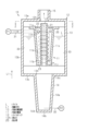
図1に示すように、気液分離装置10は、気液分離器11と、オイルタンク12と、を備える。気液分離装置10から排出されたオイルLは、内燃機関の潤滑部位に供給される。なお、図1の上下方向が重力方向である。
An embodiment of a gas-liquid separation device mounted on an internal combustion engine, which is a driving source of a vehicle, will be described below with reference to FIGS. 1 and 2. FIG.
<Basic configuration of gas-liquid separation device>
As shown in FIG. 1 , the gas-
スカベンジングポンプP1によって内燃機関のクランクケースからブローバイガスを含んだオイルLが吸引される。スカベンジングポンプP1によって吸引されたオイルLは、オイル導入管31を介して気液分離器11に導入される。気液分離器11は、内燃機関のクランクケースから導入されたオイルLからブローバイガスを分離させる。オイルタンク12は、内燃機関の潤滑部位に供給されるオイルLを貯留する。オイルタンク12には、気液分離器11によってブローバイガスが分離されたオイルLが貯留される。オイルタンク12に貯留されたオイルLは、オイルタンク12から排出流路32に排出される。排出流路32に排出されたオイルLは、フィードポンプP2によって内燃機関の潤滑部位に圧送される。なお、以下の気液分離装置10の構成の位置に関する説明は、特に言及しない限り、車両が水平面上に停車しているときの位置の説明である。
Oil L containing blow-by gas is sucked from the crankcase of the internal combustion engine by the scavenging pump P1. The oil L sucked by the scavenging pump P1 is introduced into the gas-
<オイルタンクの構成>
オイルタンク12は、気液分離器11を収容する。オイルタンク12は、第1タンク部13と第2タンク部14を有していてもよい。第1タンク部13は、矩形箱状である。第1タンク部13は、矩形板状の第1壁13aと、矩形筒状の第2壁13bと、矩形板状の第3壁13cと、を有する。第2壁13bは、第1壁13aの縁部と第3壁13cの縁部とを接続している。オイル導入管31は、第2壁13bを貫通しているとともに、第1タンク部13の外部と内部との間で延びている。第3壁13cは、第1壁13aよりも重力方向の下方に位置する。第3壁13cの中央には、第3壁13cを貫通する貫通孔13hが位置する。第1タンク部13の軸線が延びる方向を軸線方向L1という。
<Configuration of oil tank>
The
オイルタンク12は、ドライサンプ式のオイルタンクである。オイルタンク12は、ブローバイガスを外部に排出するための排出口12hを有している。排出口12hは、第1タンク部13の第1壁13aを貫通する円孔である。排出口12hは第1壁13aの中央に位置する。
The
第1壁13aには円筒状の排出管15が接続されている。排出管15は排出口12hを介して第1タンク部13の内部と連通している。ブローバイガスは、オイルタンク12の内部から排出口12hを介して排出管15に排出される。ブローバイガスは、排出管15を経由して、内燃機関の吸気通路に導入される。
A
第2タンク部14は、有底の円筒状である。第2タンク部14は、円筒状の筒部14aと、円形板状の底部14bと、を有する。筒部14aの軸線は軸線方向L1に延びる。筒部14aの軸線の延長上に第1タンク部13の軸線が位置してもよい。
The
筒部14aの一端を第1端14cといい、他端を第2端14dという。底部14bは、筒部14aに対して第2端14dを塞ぐように位置する。第2端14dから第1端14cに近づくにつれて、筒部14aの径方向における寸法が大きくなっている。第2タンク部14は、第1タンク部13よりも重力方向の下方に位置する。筒部14aの第1端14cが第1タンク部13の第3壁13cに接続されている。第2タンク部14の内部は、第3壁13cの貫通孔13hを介して第1タンク部13の内部と連通している。
One end of the
オイルタンク12のうち、第2タンク部14の底部14bが重力方向における最下部に位置する。オイルタンク12に貯留されるオイルLは、第2タンク部14の内部全体に満たされている。オイルLは、第1タンク部13の内部のうち、重力方向における下部に満たされている。その他の第1タンク部13内の部分は、オイルLが満たされていない。オイルLの液面は、第1タンク部13の内部に位置している。
In the
筒部14a及び底部14bの少なくとも一方には、排出流路32が連通している。第2タンク部14の内部のオイルLが排出流路32に導入される。
<気液分離器の構成>
気液分離器11は筒状である。気液分離器11の軸線を分離器軸線L2という。分離器軸線L2は、軸線方向L1に延びる。分離器軸線L2は、第1タンク部13の軸線と一致していてもよい。すなわち、軸線方向L1は、気液分離器11の軸線方向に相当する。
A
<Configuration of gas-liquid separator>
The gas-
気液分離器11の一端を第1開口端11aといい、他端を第2開口端11bという。第2開口端11bは、第1開口端11aよりも重力方向の下方に位置する。気液分離器11は、第2開口端11bから第1開口端11aに近づくにつれて、気液分離器11の径方向における寸法が大きくなっている。
One end of the gas-
第1開口端11aは、第2開口端11bと比較して、排出口12hとの間の距離が短い。すなわち、第1開口端11aは、気液分離器11の軸線方向L1における端部のうち、排出口12hとの間の距離が短い方の端部に相当する。
The first
分離器軸線L2の延長上に排出口12hが位置する。詳細には、分離器軸線L2の延長上に排出口12hの中心が位置する。第1開口端11aにおける気液分離器11の内径は、排出口12hの径よりも大きい。
A
気液分離器11はオイル導入孔11hを有する。オイル導入孔11hは気液分離器11の外面11cと内面11dとの間を貫通している。気液分離器11の外面11cは、オイルタンク12の第2壁13bの内面と対向している。気液分離器11には、オイル導入管31の端部が接続されている。オイル導入孔11hを介して、オイル導入管31は気液分離器11の内部と連通している。
The gas-
図1及び図2に示すように、気液分離器11は、支持板33によって第1タンク部13に支持されている。支持板33は、気液分離器11の外面11cと第2壁13bの内面との間で延びている。支持板33は、第1タンク部13の内部に4つ配置されている。
As shown in FIGS. 1 and 2 , the gas-
気液分離器11の内部には、軸線方向L1に延びる内部管21が位置する。内部管21は円筒状である。内部管21の軸線は分離器軸線L2と一致していてもよい。内部管21の一端は、気液分離器11の第1開口端11aから気液分離器11の外部に露出している。内部管21の他端は、気液分離器11の第2開口端11bから気液分離器11の外部に露出している。内部管21の外周面は気液分離器11の内面11dから離れている。これにより、気液分離器11の内面11dと内部管21の外周面とによって、気液分離器11の内部空間が区画されている。
An
内部管21は4つの第1支持部22を有する。内部管21は、第1支持部22によって気液分離器11に支持されている。第1支持部22は、内部管21の外周面から突出する軸状である。第1支持部22は、内部管21における両端の間から延びている。内部管21と接続される第1支持部22の端部を基端とすると、第1支持部22の先端は、気液分離器11の内面11dに固定されている。内部管21の周方向において、第1支持部22は互いに離れている。
The
内部管21は、第2支持部23によって支持板33に支持されている。第2支持部23は、内部管21の外周面から延びる板状である。第2支持部23は、軸線方向L1からみて環状をなす。第2支持部23は、第2開口端11bから気液分離器11の外部に露出する内部管21の端部から延びている。第2支持部23の外周縁は、4つの支持板33に固定されている。これにより、内部管21は、支持板33を介して第1タンク部13に支持されている。
The
軸線方向L1において、第2支持部23は気液分離器11の第2開口端11bから離れている。これにより、気液分離器11の軸線方向L1における下方には、第2開口端11bと第2支持部23とで区画された空間であるオイル排出部11jが位置している。オイル排出部11jを介して、気液分離器11の内部空間が気液分離器11の外部と連通している。
The
気液分離器11は延出部25を備える。延出部25は、気液分離器11の外面11cのうち排出口12h側の端部に接続されている。延出部25は、気液分離器11の外面11cから第2壁13bの内面に向かって延びている。延出部25は、軸線方向L1に直交するように延びる板状である。延出部25は、軸線方向L1からみて環状である。延出部25は、気液分離器11の第1開口端11aから気液分離器11の外方に向かって延びている。延出部25の外周縁は、第1タンク部13の内面から離れている。延出部25の外周縁は、支持板33に固定されていてもよい。
The gas-
<オイル及びブローバイガスの流れ>
次に、気液分離装置10におけるオイルL及びブローバイガスの流れについて説明する。
<Flow of oil and blow-by gas>
Next, the flow of the oil L and the blow-by gas in the gas-
図1に示すように、オイルLは、内燃機関のクランクケースからオイル導入管31を経由して気液分離器11の内部に導入される。このオイルLにはブローバイガスが含まれている。気液分離器11の内部にオイルLが導入されるとき、オイルLは、オイル導入孔11hから気液分離器11の内部を流れる。このときのオイルLの流れを図1に二点鎖線の矢印で示す。オイルLは、気液分離器11の内部を螺旋状に流れつつ、第1開口端11aから第2開口端11bに向かって流れる。オイルLは、内部管21の周りを流れる。
As shown in FIG. 1, the oil L is introduced into the gas-
オイルLが気液分離器11の内部を流れる間、オイルLには遠心力が作用する。この遠心力により、オイルLからブローバイガスが分離される。気液分離器11によってオイルLから分離されたブローバイガスは、気液分離器11の第1開口端11aから気液分離器11の外部に排出される。このブローバイガスは、排出管15を経由して、内燃機関の吸気通路に導入される。排出管15におけるブローバイガスの流れを図1に破線の矢印で示す。
Centrifugal force acts on the oil L while it flows through the gas-
気液分離器11の内部を流れるオイルLが第2開口端11bに至ると、オイルLは、オイル排出部11jを介して第1タンク部13の内部に流れ出る。こうして気液分離器11によってブローバイガスが分離されたオイルLが、オイルタンク12の内部に貯留される。オイルタンク12の内部に貯留されたオイルLにブローバイガスが残っている場合、このブローバイガスはオイルタンク12から内部管21の内部に導入される。内部管21の内部に導入されたブローバイガスは、内部管21の内部を流れた後、排出管15に導入される。オイルタンク12の内部に貯留されたオイルLは、オイルタンク12から排出流路32を経由して内燃機関の潤滑部位に供給される。
When the oil L flowing inside the gas-
<作用>
次に本実施形態の作用について説明する。
車両の走行中等、気液分離装置10に遠心力が作用する状況下では、オイルLの液面が、車両が停止しているときのオイルLの液面に対して傾くことがある。とくに、車両が旋回した場合や車両速度が急速に加速または減速された場合、オイルタンク12の内部でオイルLの液面が大きく傾くことがある。オイルLの液面が傾くと、オイルタンク12の内部で排出口12hに向かうオイルLの流れが生じる。こうした流れによって、オイルLは、排出口12hを介してオイルタンク12から排出管15にオイルLが漏れ出るおそれがある。
<Action>
Next, the operation of this embodiment will be described.
Under conditions where centrifugal force acts on the gas-
本実施形態では、気液分離器11が第1開口端11aから気液分離器11の外方に向かって延びる延出部25を有する。そのため、オイルLの液面が、車両が停止しているときのオイルLの液面に対して傾いたときに、オイルタンク12の内部で排出口12hに向かうオイルLの流れを延出部25によって堰き止めることができる。これにより、排出口12hを介して排出管15にオイルLが漏れ出ることを抑制できる。
In this embodiment, the gas-
<効果>
上記実施形態によれば、以下の効果を得ることができる。
(1)延出部25によって排出口12hに向かうオイルLの流れを堰き止めることができる。そのため、排出口12hからオイルタンク12の外部にオイルLが漏れ出ることを抑制できる。したがって、気液分離装置10から内燃機関の潤滑部位へと供給されるオイルLの量が減少しにくい。
<effect>
According to the above embodiment, the following effects can be obtained.
(1) The extending
(2)オイルタンク12から排出管15にオイルLが漏れ出ると、オイルLが排出管15を経由して内燃機関の吸気通路に導入されるおそれがある。このオイルLが内燃機関の吸気通路から燃焼室に至ると、オイルLの燃焼に伴う白煙が生じるおそれがある。上記実施形態によれば、オイルタンク12から排出管15へのオイルLの漏出が抑制できるため、そうしたオイルLの漏出に伴って生じる上記の白煙の発生を抑制できる。
(2) If the oil L leaks from the
<変更例>
上記実施形態は、以下のように変更して実施することができる。上記実施形態及び以下の変更例は、技術的に矛盾しない範囲で互いに組み合わせて実施することができる。
<Change example>
The above embodiment can be implemented with the following modifications. The above embodiments and the following modifications can be combined with each other within a technically consistent range.
・延出部25は、軸線方向L1に直交していなくてもよい。この変更例での延出部25は、上記実施形態での延出部25に対して傾斜する。
・延出部25は、軸線方向L1からみて環状をなすものに限らない。例えば延出部25は、気液分離器11の周方向において複数に分割された形状であってもよい。延出部25における分割された部分同士が、気液分離器11の周方向において互いに離れていてもよい。
- The extending
- The extending
・延出部25の形状は板状に限らない。要するに、延出部25は、第1開口端11aから気液分離器11の外方に向かって延びる形状であればよい。
・延出部25は、第1タンク部13の内面に接していてもよい。
- The shape of the extending
- The extending
・延出部25は、気液分離器11の外面11cのうち排出口12h側の端部よりも第3壁13c側に配置されていてもよい。すなわち、本開示において、気液分離器11の端部とは、厳密な意味での端部の他、延出部25が延出する部位であって、オイルLの液面の傾きを小さくして排出口12hからのオイルLの流出を減少させることのできる部位である。
- The extending
L…オイル
L1…軸線方向
10…気液分離装置
11…気液分離器
12…オイルタンク
12h…排出口
25…延出部
L... Oil L1...
Claims (1)
前記内燃機関の潤滑部位に供給されるオイルを貯留するオイルタンクと、
前記オイルタンクに収容された筒状の気液分離器と、を備え、
前記オイルタンクは、ブローバイガスを外部に排出するための排出口を有し、
前記気液分離器は、前記気液分離器の軸線方向における端部のうち、前記排出口との間の距離が短い方の端部から前記気液分離器の外方に向かって延びる延出部を有する気液分離装置。 A gas-liquid separation device for separating blow-by gas from oil introduced from a crankcase of an internal combustion engine,
an oil tank that stores oil to be supplied to lubricated parts of the internal combustion engine;
a cylindrical gas-liquid separator housed in the oil tank,
The oil tank has an outlet for discharging blow-by gas to the outside,
The gas-liquid separator extends outwardly of the gas-liquid separator from one of the ends of the gas-liquid separator in the axial direction that is closer to the discharge port. A gas-liquid separator having a part.
Priority Applications (1)
| Application Number | Priority Date | Filing Date | Title |
|---|---|---|---|
| JP2021185773A JP7666302B2 (en) | 2021-11-15 | 2021-11-15 | Gas-liquid separator |
Applications Claiming Priority (1)
| Application Number | Priority Date | Filing Date | Title |
|---|---|---|---|
| JP2021185773A JP7666302B2 (en) | 2021-11-15 | 2021-11-15 | Gas-liquid separator |
Publications (2)
| Publication Number | Publication Date |
|---|---|
| JP2023072995A true JP2023072995A (en) | 2023-05-25 |
| JP7666302B2 JP7666302B2 (en) | 2025-04-22 |
Family
ID=86425206
Family Applications (1)
| Application Number | Title | Priority Date | Filing Date |
|---|---|---|---|
| JP2021185773A Active JP7666302B2 (en) | 2021-11-15 | 2021-11-15 | Gas-liquid separator |
Country Status (1)
| Country | Link |
|---|---|
| JP (1) | JP7666302B2 (en) |
Citations (6)
| Publication number | Priority date | Publication date | Assignee | Title |
|---|---|---|---|---|
| JPS5328340U (en) * | 1976-08-19 | 1978-03-10 | ||
| JPH0395015U (en) * | 1990-01-18 | 1991-09-27 | ||
| JP2003172116A (en) * | 2001-12-07 | 2003-06-20 | Yamaha Marine Co Ltd | Oil tank structure for small vessel |
| JP2006083809A (en) * | 2004-09-17 | 2006-03-30 | Yamaha Motor Co Ltd | Engine-driven vehicle oil tank |
| JP2006118463A (en) * | 2004-10-22 | 2006-05-11 | Honda Motor Co Ltd | Oil tank |
| WO2007129137A1 (en) * | 2006-05-09 | 2007-11-15 | Dayco Fluid Technologies S.P.A. | Blow by gas separator device for an internal combustion engine of a motor vehicle |
-
2021
- 2021-11-15 JP JP2021185773A patent/JP7666302B2/en active Active
Patent Citations (6)
| Publication number | Priority date | Publication date | Assignee | Title |
|---|---|---|---|---|
| JPS5328340U (en) * | 1976-08-19 | 1978-03-10 | ||
| JPH0395015U (en) * | 1990-01-18 | 1991-09-27 | ||
| JP2003172116A (en) * | 2001-12-07 | 2003-06-20 | Yamaha Marine Co Ltd | Oil tank structure for small vessel |
| JP2006083809A (en) * | 2004-09-17 | 2006-03-30 | Yamaha Motor Co Ltd | Engine-driven vehicle oil tank |
| JP2006118463A (en) * | 2004-10-22 | 2006-05-11 | Honda Motor Co Ltd | Oil tank |
| WO2007129137A1 (en) * | 2006-05-09 | 2007-11-15 | Dayco Fluid Technologies S.P.A. | Blow by gas separator device for an internal combustion engine of a motor vehicle |
Also Published As
| Publication number | Publication date |
|---|---|
| JP7666302B2 (en) | 2025-04-22 |
Similar Documents
| Publication | Publication Date | Title |
|---|---|---|
| US7401599B2 (en) | Vapor-liquid separator | |
| US7871461B2 (en) | Bubble separator | |
| JP4622868B2 (en) | Bubble separator | |
| US6475256B2 (en) | Cyclone type gas-liquid separator | |
| WO2015068398A1 (en) | Oil separation device of internal combustion engine | |
| JP7666302B2 (en) | Gas-liquid separator | |
| JP4626587B2 (en) | Gas-liquid separator | |
| JP6010011B2 (en) | Breather system for internal combustion engines | |
| JP5516112B2 (en) | Blow-by gas reduction device | |
| CN111237080A (en) | Engine and all-terrain vehicle | |
| JP6385118B2 (en) | Rotary compressor | |
| JPH08135419A (en) | Lubricating method for 4-cycle engine and 4-cycle engine using the method | |
| JP2008038714A (en) | Gas liquid separator | |
| JPH0751204B2 (en) | Air bubble separation device in liquid | |
| CN106979047B (en) | Oil sump with the oil scupper for being exclusively used in positive crankcase ventilation (PCV) | |
| JP2015140700A (en) | Gas-liquid separation structure of internal combustion engine | |
| JP6988439B2 (en) | Oil separator | |
| KR100398525B1 (en) | Device to prevent tilting oil in oil pan for vehicle | |
| CN110388279A (en) | The machine oil storage organization and internal combustion engine of internal combustion engine | |
| JP5034357B2 (en) | Gas-liquid separator | |
| JP2020122468A (en) | Oil pan | |
| JP2001518374A5 (en) | ||
| US11371399B2 (en) | Oil return structure | |
| JP2009103081A (en) | Blow-by gas reducing apparatus | |
| JP2021181779A (en) | Oil returning structure of internal combustion engine |
Legal Events
| Date | Code | Title | Description |
|---|---|---|---|
| A621 | Written request for application examination |
Free format text: JAPANESE INTERMEDIATE CODE: A621 Effective date: 20240320 |
|
| A977 | Report on retrieval |
Free format text: JAPANESE INTERMEDIATE CODE: A971007 Effective date: 20241219 |
|
| A131 | Notification of reasons for refusal |
Free format text: JAPANESE INTERMEDIATE CODE: A131 Effective date: 20241224 |
|
| A521 | Request for written amendment filed |
Free format text: JAPANESE INTERMEDIATE CODE: A523 Effective date: 20250210 |
|
| TRDD | Decision of grant or rejection written | ||
| A01 | Written decision to grant a patent or to grant a registration (utility model) |
Free format text: JAPANESE INTERMEDIATE CODE: A01 Effective date: 20250311 |
|
| A61 | First payment of annual fees (during grant procedure) |
Free format text: JAPANESE INTERMEDIATE CODE: A61 Effective date: 20250324 |
|
| R150 | Certificate of patent or registration of utility model |
Ref document number: 7666302 Country of ref document: JP Free format text: JAPANESE INTERMEDIATE CODE: R150 |