JP2023073005A - キャニスタ - Google Patents
キャニスタ Download PDFInfo
- Publication number
- JP2023073005A JP2023073005A JP2021185792A JP2021185792A JP2023073005A JP 2023073005 A JP2023073005 A JP 2023073005A JP 2021185792 A JP2021185792 A JP 2021185792A JP 2021185792 A JP2021185792 A JP 2021185792A JP 2023073005 A JP2023073005 A JP 2023073005A
- Authority
- JP
- Japan
- Prior art keywords
- rod
- shaped
- chamber
- canister
- shaped portion
- Prior art date
- Legal status (The legal status is an assumption and is not a legal conclusion. Google has not performed a legal analysis and makes no representation as to the accuracy of the status listed.)
- Granted
Links
Images


Classifications
-
- F—MECHANICAL ENGINEERING; LIGHTING; HEATING; WEAPONS; BLASTING
- F02—COMBUSTION ENGINES; HOT-GAS OR COMBUSTION-PRODUCT ENGINE PLANTS
- F02M—SUPPLYING COMBUSTION ENGINES IN GENERAL WITH COMBUSTIBLE MIXTURES OR CONSTITUENTS THEREOF
- F02M25/00—Engine-pertinent apparatus for adding non-fuel substances or small quantities of secondary fuel to combustion-air, main fuel or fuel-air mixture
- F02M25/08—Engine-pertinent apparatus for adding non-fuel substances or small quantities of secondary fuel to combustion-air, main fuel or fuel-air mixture adding fuel vapours drawn from engine fuel reservoir
- F02M25/0854—Details of the absorption canister
-
- B—PERFORMING OPERATIONS; TRANSPORTING
- B01—PHYSICAL OR CHEMICAL PROCESSES OR APPARATUS IN GENERAL
- B01D—SEPARATION
- B01D53/00—Separation of gases or vapours; Recovering vapours of volatile solvents from gases; Chemical or biological purification of waste gases, e.g. engine exhaust gases, smoke, fumes, flue gases, aerosols
- B01D53/02—Separation of gases or vapours; Recovering vapours of volatile solvents from gases; Chemical or biological purification of waste gases, e.g. engine exhaust gases, smoke, fumes, flue gases, aerosols by adsorption, e.g. preparative gas chromatography
- B01D53/04—Separation of gases or vapours; Recovering vapours of volatile solvents from gases; Chemical or biological purification of waste gases, e.g. engine exhaust gases, smoke, fumes, flue gases, aerosols by adsorption, e.g. preparative gas chromatography with stationary adsorbents
- B01D53/0407—Constructional details of adsorbing systems
-
- B—PERFORMING OPERATIONS; TRANSPORTING
- B01—PHYSICAL OR CHEMICAL PROCESSES OR APPARATUS IN GENERAL
- B01D—SEPARATION
- B01D53/00—Separation of gases or vapours; Recovering vapours of volatile solvents from gases; Chemical or biological purification of waste gases, e.g. engine exhaust gases, smoke, fumes, flue gases, aerosols
- B01D53/02—Separation of gases or vapours; Recovering vapours of volatile solvents from gases; Chemical or biological purification of waste gases, e.g. engine exhaust gases, smoke, fumes, flue gases, aerosols by adsorption, e.g. preparative gas chromatography
- B01D53/04—Separation of gases or vapours; Recovering vapours of volatile solvents from gases; Chemical or biological purification of waste gases, e.g. engine exhaust gases, smoke, fumes, flue gases, aerosols by adsorption, e.g. preparative gas chromatography with stationary adsorbents
- B01D53/0407—Constructional details of adsorbing systems
- B01D53/0415—Beds in cartridges
-
- B—PERFORMING OPERATIONS; TRANSPORTING
- B60—VEHICLES IN GENERAL
- B60K—ARRANGEMENT OR MOUNTING OF PROPULSION UNITS OR OF TRANSMISSIONS IN VEHICLES; ARRANGEMENT OR MOUNTING OF PLURAL DIVERSE PRIME-MOVERS IN VEHICLES; AUXILIARY DRIVES FOR VEHICLES; INSTRUMENTATION OR DASHBOARDS FOR VEHICLES; ARRANGEMENTS IN CONNECTION WITH COOLING, AIR INTAKE, GAS EXHAUST OR FUEL SUPPLY OF PROPULSION UNITS IN VEHICLES
- B60K15/00—Arrangement in connection with fuel supply of combustion engines or other fuel consuming energy converters, e.g. fuel cells; Mounting or construction of fuel tanks
- B60K15/03—Fuel tanks
- B60K15/035—Fuel tanks characterised by venting means
- B60K15/03504—Fuel tanks characterised by venting means adapted to avoid loss of fuel or fuel vapour, e.g. with vapour recovery systems
-
- F—MECHANICAL ENGINEERING; LIGHTING; HEATING; WEAPONS; BLASTING
- F02—COMBUSTION ENGINES; HOT-GAS OR COMBUSTION-PRODUCT ENGINE PLANTS
- F02M—SUPPLYING COMBUSTION ENGINES IN GENERAL WITH COMBUSTIBLE MIXTURES OR CONSTITUENTS THEREOF
- F02M25/00—Engine-pertinent apparatus for adding non-fuel substances or small quantities of secondary fuel to combustion-air, main fuel or fuel-air mixture
- F02M25/08—Engine-pertinent apparatus for adding non-fuel substances or small quantities of secondary fuel to combustion-air, main fuel or fuel-air mixture adding fuel vapours drawn from engine fuel reservoir
- F02M25/089—Layout of the fuel vapour installation
-
- B—PERFORMING OPERATIONS; TRANSPORTING
- B01—PHYSICAL OR CHEMICAL PROCESSES OR APPARATUS IN GENERAL
- B01D—SEPARATION
- B01D2253/00—Adsorbents used in seperation treatment of gases and vapours
- B01D2253/10—Inorganic adsorbents
- B01D2253/102—Carbon
-
- B—PERFORMING OPERATIONS; TRANSPORTING
- B01—PHYSICAL OR CHEMICAL PROCESSES OR APPARATUS IN GENERAL
- B01D—SEPARATION
- B01D2257/00—Components to be removed
- B01D2257/70—Organic compounds not provided for in groups B01D2257/00 - B01D2257/602
- B01D2257/702—Hydrocarbons
-
- B—PERFORMING OPERATIONS; TRANSPORTING
- B01—PHYSICAL OR CHEMICAL PROCESSES OR APPARATUS IN GENERAL
- B01D—SEPARATION
- B01D2259/00—Type of treatment
- B01D2259/45—Gas separation or purification devices adapted for specific applications
- B01D2259/4516—Gas separation or purification devices adapted for specific applications for fuel vapour recovery systems
-
- B—PERFORMING OPERATIONS; TRANSPORTING
- B60—VEHICLES IN GENERAL
- B60K—ARRANGEMENT OR MOUNTING OF PROPULSION UNITS OR OF TRANSMISSIONS IN VEHICLES; ARRANGEMENT OR MOUNTING OF PLURAL DIVERSE PRIME-MOVERS IN VEHICLES; AUXILIARY DRIVES FOR VEHICLES; INSTRUMENTATION OR DASHBOARDS FOR VEHICLES; ARRANGEMENTS IN CONNECTION WITH COOLING, AIR INTAKE, GAS EXHAUST OR FUEL SUPPLY OF PROPULSION UNITS IN VEHICLES
- B60K15/00—Arrangement in connection with fuel supply of combustion engines or other fuel consuming energy converters, e.g. fuel cells; Mounting or construction of fuel tanks
- B60K15/03—Fuel tanks
- B60K15/035—Fuel tanks characterised by venting means
- B60K15/03504—Fuel tanks characterised by venting means adapted to avoid loss of fuel or fuel vapour, e.g. with vapour recovery systems
- B60K2015/03514—Fuel tanks characterised by venting means adapted to avoid loss of fuel or fuel vapour, e.g. with vapour recovery systems with vapor recovery means
Landscapes
- Engineering & Computer Science (AREA)
- Chemical & Material Sciences (AREA)
- Combustion & Propulsion (AREA)
- Mechanical Engineering (AREA)
- General Engineering & Computer Science (AREA)
- General Chemical & Material Sciences (AREA)
- Analytical Chemistry (AREA)
- Oil, Petroleum & Natural Gas (AREA)
- Chemical Kinetics & Catalysis (AREA)
- Life Sciences & Earth Sciences (AREA)
- Sustainable Development (AREA)
- Sustainable Energy (AREA)
- Transportation (AREA)
- Supplying Secondary Fuel Or The Like To Fuel, Air Or Fuel-Air Mixtures (AREA)
- Separation Of Gases By Adsorption (AREA)
Abstract

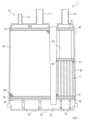
【解決手段】キャニスタは、少なくとも1つの室と、流入ポートと、大気ポートと、流出ポートと、複数の棒状部と、を備える。少なくとも1つの室は、燃料蒸気の吸着材が配置される。複数の棒状部は、少なくとも1つの室のいずれかである対象室に配された細長い部位である。対象室に配置される吸着材は、複数の粒状部材として構成されている。複数の棒状部の少なくとも一部には、その外周面に少なくとも1つの凹部が形成されている。
【選択図】図3
Description
本開示の一態様では、複数の棒状部は、対象室における気体の流れ方向に略平行に伸びてもよい。
上記構成によれば、対象室では、棒状部の凹部と吸着材との間の隙間が、該棒状部の伸長方向に沿って形成されるように促される。このため、より一層、キャニスタの通気抵抗を抑制できる。
上記構成によれば、複数の棒状部及び連結部の製造が容易になる。また、対象室に吸着材を配置する際の作業負荷を低減できる。
上記構成によれば、対象室の端部に連結部が配置されるのを回避でき、対象室の端部で大気及び燃料蒸気の流れに偏りが生じるのを抑制できる。これにより、対象室全体として、大気及び燃料蒸気の流れがより一様になるよう促すことができる。
本開示の一態様では、複数の棒状部は、少なくとも2種類の棒状部を含んでもよい。それぞれの種類の棒状部は、当該棒状部の伸長方向に直交する断面の形状が異なってもよい。
[1.キャニスタの構成]
第1実施形態のキャニスタ1は、車両に搭載される(図1参照)。以後、キャニスタ1が搭載された車両を、自車両と記載する。キャニスタ1は、第1~第3室20~40を備える合成樹脂製の容器10を有し、第1~第3室20~40には、それぞれ、燃料蒸気を吸着するための吸着材60~62が配される。なお、キャニスタ1の室の数は、例えば、2以下、又は4以上であっても良い。
また、第2室30の吸着材61は、粒状の活性炭であるペレットにより構成される(図2参照)。一例として、ペレットは、略円柱状となっており、以後、ペレットの伸長方向(換言すれば、軸方向)に直交する断面の径をRとする。しかし、ペレットの形状は、円柱状に限らず、例えば、球状等であっても良い。なお、ペレットが球状である場合、ペレットの径をRとしても良い。また、吸着材60は、ペレット以外の粒状の吸着材として構成されていても良い。
第1実施形態では、一例として、第2室30が対象室として構成され、第2室30にグリッド部材5が設けられている(図1参照)。グリッド部材5は、一例として樹脂により一体的に構成されており、複数の棒状部50と、第1及び第2連結部52、53と、第1及び第2離間部54、55とを備える(図3~5参照)。なお、グリッド部材5は、樹脂以外の材料から構成されていても良い。
グリッド部材5における各棒状部50の外周面には、少なくとも1つの凹部51が形成されている(図3~5参照)。一例として、凹部51は、第1端5A又はその付近から第2端5B又はその付近まで、棒状部50の伸長方向と略平行に伸びる溝状の部位として形成されている。また、グリッド部材5には、様々な形状の棒状部50が用いられ得る。
この他にも、例えば、断面の形状が異なる(換言すれば、凹部51の数、位置、大きさ、及び/又は、形状の異なる)2種類以上の棒状部50により、グリッド部材5を構成しても良い。具体的には、例えば、種類が異なる第1~第3棒状部を設け、第1~第3棒状部を、それぞれ、第1~第3列5C~5Eに配置しても良い(図4、5参照)。
[5.グリッド部材]
次に、第2実施形態のキャニスタ1について説明する。第2実施形態のキャニスタ1は、グリッド部材7の構成において第1実施形態と相違する。以下では、第1実施形態との相違点を中心に、第2実施形態のキャニスタ1について説明する。
(1)上記実施形態によれば、対象室である第2室30では、棒状部50、70に形成された凹部51、71と、ペレットである吸着材60との間に隙間が形成される。このため、キャニスタ1の通気抵抗を抑制できる。これにより、圧力損失の増加を抑制しつつ、キャニスタ1のL/Dを向上させることができる。
(1)上記実施形態において、グリッド部材5、7は、複数の棒状部50、70が気体の流れ方向とは異なる方向(例えば、気体の流れ方向に対し略垂直な方向)に伸びるように配置されていても良い。また、グリッド部材5、7の複数の棒状部50、70は、曲がった形状を有していても良いし、異なる長さを有していても良いし、異なる方向に延びていても良い。
Claims (8)
- エンジンを有する車両に搭載されるよう構成されたキャニスタであって、
燃料蒸気を吸着する吸着材が配置された少なくとも1つの室と、
前記車両の燃料タンクから、前記少なくとも1つの室に燃料蒸気を流入させるよう構成された流入ポートと、
前記車両の外部から、前記少なくとも1つの室に大気を流入させるよう構成された大気ポートと、
前記大気ポートから流入した前記大気により、前記吸着材に吸着した燃料蒸気を前記エンジンに向けて流出させるよう構成された流出ポートと、
前記少なくとも1つの室のいずれかである対象室に配された細長い複数の棒状部と、を備え、
前記対象室に配置される前記吸着材は、複数の粒状部材として構成されており、
前記複数の棒状部の少なくとも一部には、その外周面に少なくとも1つの凹部が形成されている
キャニスタ。 - 請求項1に記載のキャニスタであって、
前記複数の棒状部は、前記対象室における気体の流れ方向に略平行に伸びる
キャニスタ。 - 請求項1又は請求項2に記載のキャニスタであって、
前記少なくとも1つの凹部は、当該少なくとも1つの凹部が設けられた棒状部の伸長方向と略平行に伸びる溝状の部位である
キャニスタ。 - 請求項3に記載のキャニスタであって、
前記対象室に配置される吸着材である前記複数の粒状部材の各々は、略円柱状に形成されており、
前記少なくとも1つの凹部の幅は、前記複数の粒状部材の各々における伸長方向に直交する断面の径よりも狭い
キャニスタ。 - 請求項1から請求項4のうちのいずれか1項に記載のキャニスタであって、
前記複数の棒状部の各々を、他の棒状部に連結する連結部をさらに備え、
前記連結部は、前記複数の棒状部の端部に設けられる
キャニスタ。 - 請求項1から請求項4のうちのいずれか1項に記載のキャニスタであって、
前記複数の棒状部の各々を、他の棒状部に連結する連結部をさらに備え、
前記連結部は、前記複数の棒状部の端部から離れた位置に設けられる
キャニスタ。 - 請求項1から請求項6のうちのいずれか1項に記載のキャニスタであって、
前記複数の棒状部は、少なくとも1つの特定棒状部を含み、
前記特定棒状部は、前記少なくとも1つの凹部が設けられていると共に、当該特定棒状部の伸長方向に並ぶ少なくとも2つの区間を有し、
隣接する前記区間は、前記特定棒状部の伸長方向に直交する断面の形状が異なる
キャニスタ。 - 請求項1から請求項7のうちのいずれか1項に記載のキャニスタであって、
前記複数の棒状部は、少なくとも2種類の棒状部を含み、
それぞれの種類の前記棒状部は、当該棒状部の伸長方向に直交する断面の形状が異なる
キャニスタ。
Priority Applications (3)
| Application Number | Priority Date | Filing Date | Title |
|---|---|---|---|
| JP2021185792A JP7444838B2 (ja) | 2021-11-15 | 2021-11-15 | キャニスタ |
| US17/979,382 US12209563B2 (en) | 2021-11-15 | 2022-11-02 | Canister |
| CN202211421576.6A CN116122998B (zh) | 2021-11-15 | 2022-11-14 | 过滤罐 |
Applications Claiming Priority (1)
| Application Number | Priority Date | Filing Date | Title |
|---|---|---|---|
| JP2021185792A JP7444838B2 (ja) | 2021-11-15 | 2021-11-15 | キャニスタ |
Publications (2)
| Publication Number | Publication Date |
|---|---|
| JP2023073005A true JP2023073005A (ja) | 2023-05-25 |
| JP7444838B2 JP7444838B2 (ja) | 2024-03-06 |
Family
ID=86310700
Family Applications (1)
| Application Number | Title | Priority Date | Filing Date |
|---|---|---|---|
| JP2021185792A Active JP7444838B2 (ja) | 2021-11-15 | 2021-11-15 | キャニスタ |
Country Status (3)
| Country | Link |
|---|---|
| US (1) | US12209563B2 (ja) |
| JP (1) | JP7444838B2 (ja) |
| CN (1) | CN116122998B (ja) |
Families Citing this family (2)
| Publication number | Priority date | Publication date | Assignee | Title |
|---|---|---|---|---|
| JP7586804B2 (ja) * | 2021-11-15 | 2024-11-19 | フタバ産業株式会社 | キャニスタ |
| US20250001349A1 (en) * | 2023-06-29 | 2025-01-02 | Trajan Scientific Americas Inc. | Inline fluid purifier |
Citations (3)
| Publication number | Priority date | Publication date | Assignee | Title |
|---|---|---|---|---|
| JPH05202818A (ja) * | 1992-01-30 | 1993-08-10 | Toyoda Gosei Co Ltd | 蒸発燃料処理装置 |
| JP2009191688A (ja) * | 2008-02-13 | 2009-08-27 | Futaba Industrial Co Ltd | キャニスタ |
| JP2020112164A (ja) * | 2017-12-20 | 2020-07-27 | フタバ産業株式会社 | キャニスタ |
Family Cites Families (14)
| Publication number | Priority date | Publication date | Assignee | Title |
|---|---|---|---|---|
| US4750923A (en) | 1985-11-08 | 1988-06-14 | Aisan Kogyo Kabushiki Kaisha | Canister for reducing fuel vapor loss |
| JP3565789B2 (ja) * | 2001-03-06 | 2004-09-15 | 本田技研工業株式会社 | 蒸発燃料処理装置 |
| JP2009156030A (ja) | 2007-12-25 | 2009-07-16 | Mahle Filter Systems Japan Corp | 蒸発燃料処理装置 |
| US8545610B2 (en) * | 2010-07-30 | 2013-10-01 | Aisan Kogyo Kabushiki Kaisha | Fuel vapor treating apparatuses having a high thermal conductive honeycomb core |
| JP6594758B2 (ja) | 2015-12-10 | 2019-10-23 | 株式会社マーレ フィルターシステムズ | キャニスタ用ヒータ |
| JP6507092B2 (ja) * | 2015-12-17 | 2019-04-24 | フタバ産業株式会社 | 蒸発燃料処理装置 |
| JP6591955B2 (ja) | 2016-12-12 | 2019-10-16 | フタバ産業株式会社 | キャニスタ |
| JP6725483B2 (ja) * | 2017-12-20 | 2020-07-22 | フタバ産業株式会社 | キャニスタ |
| JP6901452B2 (ja) * | 2018-10-23 | 2021-07-14 | フタバ産業株式会社 | キャニスタ |
| JP7071324B2 (ja) * | 2019-12-27 | 2022-05-18 | フタバ産業株式会社 | キャニスタ |
| JP7317751B2 (ja) | 2020-03-11 | 2023-07-31 | 愛三工業株式会社 | キャニスタ |
| JP7381516B2 (ja) | 2021-04-16 | 2023-11-15 | フタバ産業株式会社 | キャニスタ |
| JP7303241B2 (ja) | 2021-04-16 | 2023-07-04 | フタバ産業株式会社 | キャニスタ |
| JP7586804B2 (ja) * | 2021-11-15 | 2024-11-19 | フタバ産業株式会社 | キャニスタ |
-
2021
- 2021-11-15 JP JP2021185792A patent/JP7444838B2/ja active Active
-
2022
- 2022-11-02 US US17/979,382 patent/US12209563B2/en active Active
- 2022-11-14 CN CN202211421576.6A patent/CN116122998B/zh active Active
Patent Citations (3)
| Publication number | Priority date | Publication date | Assignee | Title |
|---|---|---|---|---|
| JPH05202818A (ja) * | 1992-01-30 | 1993-08-10 | Toyoda Gosei Co Ltd | 蒸発燃料処理装置 |
| JP2009191688A (ja) * | 2008-02-13 | 2009-08-27 | Futaba Industrial Co Ltd | キャニスタ |
| JP2020112164A (ja) * | 2017-12-20 | 2020-07-27 | フタバ産業株式会社 | キャニスタ |
Also Published As
| Publication number | Publication date |
|---|---|
| CN116122998A (zh) | 2023-05-16 |
| US20230151783A1 (en) | 2023-05-18 |
| US12209563B2 (en) | 2025-01-28 |
| CN116122998B (zh) | 2026-04-24 |
| JP7444838B2 (ja) | 2024-03-06 |
Similar Documents
| Publication | Publication Date | Title |
|---|---|---|
| JP6507092B2 (ja) | 蒸発燃料処理装置 | |
| US8801840B2 (en) | Evaporated fuel treating device | |
| US9328700B2 (en) | Fuel vapor processing apparatus | |
| US10221812B2 (en) | Canister | |
| JP7303241B2 (ja) | キャニスタ | |
| JP5220631B2 (ja) | 蒸発燃料処理装置 | |
| JP7381516B2 (ja) | キャニスタ | |
| US9283513B2 (en) | Fuel vapor treatment device | |
| JP2017014995A (ja) | 蒸発燃料処理装置 | |
| JP7444838B2 (ja) | キャニスタ | |
| US9334836B2 (en) | Evaporation fuel processing device | |
| US20140060497A1 (en) | Evaporation fuel processing device | |
| JP6628992B2 (ja) | 蒸発燃料処理装置 | |
| CN116122997B (zh) | 过滤罐 | |
| JP2024030864A (ja) | キャニスタ | |
| JP7181254B2 (ja) | 蒸発燃料処理装置 | |
| JP7779881B2 (ja) | キャニスタ | |
| JP2025014305A (ja) | キャニスタ | |
| JP2020148174A (ja) | キャニスタ | |
| JP2018084195A (ja) | 吸着材およびそれを用いたキャニスタ |
Legal Events
| Date | Code | Title | Description |
|---|---|---|---|
| A621 | Written request for application examination |
Free format text: JAPANESE INTERMEDIATE CODE: A621 Effective date: 20221109 |
|
| A977 | Report on retrieval |
Free format text: JAPANESE INTERMEDIATE CODE: A971007 Effective date: 20230913 |
|
| A131 | Notification of reasons for refusal |
Free format text: JAPANESE INTERMEDIATE CODE: A131 Effective date: 20230926 |
|
| A521 | Request for written amendment filed |
Free format text: JAPANESE INTERMEDIATE CODE: A523 Effective date: 20231122 |
|
| TRDD | Decision of grant or rejection written | ||
| A01 | Written decision to grant a patent or to grant a registration (utility model) |
Free format text: JAPANESE INTERMEDIATE CODE: A01 Effective date: 20240130 |
|
| A61 | First payment of annual fees (during grant procedure) |
Free format text: JAPANESE INTERMEDIATE CODE: A61 Effective date: 20240222 |
|
| R150 | Certificate of patent or registration of utility model |
Ref document number: 7444838 Country of ref document: JP Free format text: JAPANESE INTERMEDIATE CODE: R150 |