JP2023123788A - Non-linear clipping adaptive loop filter - Google Patents
Non-linear clipping adaptive loop filter Download PDFInfo
- Publication number
- JP2023123788A JP2023123788A JP2023109613A JP2023109613A JP2023123788A JP 2023123788 A JP2023123788 A JP 2023123788A JP 2023109613 A JP2023109613 A JP 2023109613A JP 2023109613 A JP2023109613 A JP 2023109613A JP 2023123788 A JP2023123788 A JP 2023123788A
- Authority
- JP
- Japan
- Prior art keywords
- filter
- alf
- clipping
- luma
- sample
- Prior art date
- Legal status (The legal status is an assumption and is not a legal conclusion. Google has not performed a legal analysis and makes no representation as to the accuracy of the status listed.)
- Granted
Links
Images




Classifications
-
- H—ELECTRICITY
- H04—ELECTRIC COMMUNICATION TECHNIQUE
- H04N—PICTORIAL COMMUNICATION, e.g. TELEVISION
- H04N19/00—Methods or arrangements for coding, decoding, compressing or decompressing digital video signals
- H04N19/10—Methods or arrangements for coding, decoding, compressing or decompressing digital video signals using adaptive coding
- H04N19/102—Methods or arrangements for coding, decoding, compressing or decompressing digital video signals using adaptive coding characterised by the element, parameter or selection affected or controlled by the adaptive coding
- H04N19/117—Filters, e.g. for pre-processing or post-processing
-
- H—ELECTRICITY
- H04—ELECTRIC COMMUNICATION TECHNIQUE
- H04N—PICTORIAL COMMUNICATION, e.g. TELEVISION
- H04N19/00—Methods or arrangements for coding, decoding, compressing or decompressing digital video signals
- H04N19/10—Methods or arrangements for coding, decoding, compressing or decompressing digital video signals using adaptive coding
- H04N19/102—Methods or arrangements for coding, decoding, compressing or decompressing digital video signals using adaptive coding characterised by the element, parameter or selection affected or controlled by the adaptive coding
- H04N19/132—Sampling, masking or truncation of coding units, e.g. adaptive resampling, frame skipping, frame interpolation or high-frequency transform coefficient masking
-
- H—ELECTRICITY
- H04—ELECTRIC COMMUNICATION TECHNIQUE
- H04N—PICTORIAL COMMUNICATION, e.g. TELEVISION
- H04N19/00—Methods or arrangements for coding, decoding, compressing or decompressing digital video signals
- H04N19/10—Methods or arrangements for coding, decoding, compressing or decompressing digital video signals using adaptive coding
- H04N19/134—Methods or arrangements for coding, decoding, compressing or decompressing digital video signals using adaptive coding characterised by the element, parameter or criterion affecting or controlling the adaptive coding
- H04N19/136—Incoming video signal characteristics or properties
- H04N19/14—Coding unit complexity, e.g. amount of activity or edge presence estimation
-
- H—ELECTRICITY
- H04—ELECTRIC COMMUNICATION TECHNIQUE
- H04N—PICTORIAL COMMUNICATION, e.g. TELEVISION
- H04N19/00—Methods or arrangements for coding, decoding, compressing or decompressing digital video signals
- H04N19/10—Methods or arrangements for coding, decoding, compressing or decompressing digital video signals using adaptive coding
- H04N19/169—Methods or arrangements for coding, decoding, compressing or decompressing digital video signals using adaptive coding characterised by the coding unit, i.e. the structural portion or semantic portion of the video signal being the object or the subject of the adaptive coding
- H04N19/17—Methods or arrangements for coding, decoding, compressing or decompressing digital video signals using adaptive coding characterised by the coding unit, i.e. the structural portion or semantic portion of the video signal being the object or the subject of the adaptive coding the unit being an image region, e.g. an object
- H04N19/176—Methods or arrangements for coding, decoding, compressing or decompressing digital video signals using adaptive coding characterised by the coding unit, i.e. the structural portion or semantic portion of the video signal being the object or the subject of the adaptive coding the unit being an image region, e.g. an object the region being a block, e.g. a macroblock
-
- H—ELECTRICITY
- H04—ELECTRIC COMMUNICATION TECHNIQUE
- H04N—PICTORIAL COMMUNICATION, e.g. TELEVISION
- H04N19/00—Methods or arrangements for coding, decoding, compressing or decompressing digital video signals
- H04N19/10—Methods or arrangements for coding, decoding, compressing or decompressing digital video signals using adaptive coding
- H04N19/169—Methods or arrangements for coding, decoding, compressing or decompressing digital video signals using adaptive coding characterised by the coding unit, i.e. the structural portion or semantic portion of the video signal being the object or the subject of the adaptive coding
- H04N19/182—Methods or arrangements for coding, decoding, compressing or decompressing digital video signals using adaptive coding characterised by the coding unit, i.e. the structural portion or semantic portion of the video signal being the object or the subject of the adaptive coding the unit being a pixel
-
- H—ELECTRICITY
- H04—ELECTRIC COMMUNICATION TECHNIQUE
- H04N—PICTORIAL COMMUNICATION, e.g. TELEVISION
- H04N19/00—Methods or arrangements for coding, decoding, compressing or decompressing digital video signals
- H04N19/10—Methods or arrangements for coding, decoding, compressing or decompressing digital video signals using adaptive coding
- H04N19/169—Methods or arrangements for coding, decoding, compressing or decompressing digital video signals using adaptive coding characterised by the coding unit, i.e. the structural portion or semantic portion of the video signal being the object or the subject of the adaptive coding
- H04N19/186—Methods or arrangements for coding, decoding, compressing or decompressing digital video signals using adaptive coding characterised by the coding unit, i.e. the structural portion or semantic portion of the video signal being the object or the subject of the adaptive coding the unit being a colour or a chrominance component
-
- H—ELECTRICITY
- H04—ELECTRIC COMMUNICATION TECHNIQUE
- H04N—PICTORIAL COMMUNICATION, e.g. TELEVISION
- H04N19/00—Methods or arrangements for coding, decoding, compressing or decompressing digital video signals
- H04N19/42—Methods or arrangements for coding, decoding, compressing or decompressing digital video signals characterised by implementation details or hardware specially adapted for video compression or decompression, e.g. dedicated software implementation
- H04N19/439—Methods or arrangements for coding, decoding, compressing or decompressing digital video signals characterised by implementation details or hardware specially adapted for video compression or decompression, e.g. dedicated software implementation using cascaded computational arrangements for performing a single operation, e.g. filtering
-
- H—ELECTRICITY
- H04—ELECTRIC COMMUNICATION TECHNIQUE
- H04N—PICTORIAL COMMUNICATION, e.g. TELEVISION
- H04N19/00—Methods or arrangements for coding, decoding, compressing or decompressing digital video signals
- H04N19/70—Methods or arrangements for coding, decoding, compressing or decompressing digital video signals characterised by syntax aspects related to video coding, e.g. related to compression standards
-
- H—ELECTRICITY
- H04—ELECTRIC COMMUNICATION TECHNIQUE
- H04N—PICTORIAL COMMUNICATION, e.g. TELEVISION
- H04N19/00—Methods or arrangements for coding, decoding, compressing or decompressing digital video signals
- H04N19/80—Details of filtering operations specially adapted for video compression, e.g. for pixel interpolation
- H04N19/82—Details of filtering operations specially adapted for video compression, e.g. for pixel interpolation involving filtering within a prediction loop
-
- H—ELECTRICITY
- H04—ELECTRIC COMMUNICATION TECHNIQUE
- H04N—PICTORIAL COMMUNICATION, e.g. TELEVISION
- H04N19/00—Methods or arrangements for coding, decoding, compressing or decompressing digital video signals
- H04N19/85—Methods or arrangements for coding, decoding, compressing or decompressing digital video signals using pre-processing or post-processing specially adapted for video compression
- H04N19/86—Methods or arrangements for coding, decoding, compressing or decompressing digital video signals using pre-processing or post-processing specially adapted for video compression involving reduction of coding artifacts, e.g. of blockiness
Landscapes
- Engineering & Computer Science (AREA)
- Multimedia (AREA)
- Signal Processing (AREA)
- Computing Systems (AREA)
- Theoretical Computer Science (AREA)
- Compression Or Coding Systems Of Tv Signals (AREA)
- Image Processing (AREA)
- Picture Signal Circuits (AREA)
Abstract
Description
本発明は、ビデオコンポーネントのブロックの符号化又は復号に関する。本発明の実施形態は、そのような構成要素のサンプルをフィルタリングするためのフィルタを制御するときに特に使用されるが、これに限定されるものではなく、特に、排他的ではないが、アダプティブループフィルタ(adaptive loop filter)の制御に関する。 The present invention relates to encoding or decoding blocks of video components. Embodiments of the present invention find particular, but not exclusive, use in controlling filters for filtering samples of such constituents, particularly, but not exclusively, adaptive loops Concerning the control of the filter (adaptive loop filter).
ビデオ符号化は、画像符号化を含む(画像がビデオの単一フレームに相当する)。ビデオ符号化では、変換係数の量子化や動き補償(補間フィルタを使用して行われることが多い)などの一部の符号化ツールでは、しばしば歪みバイアス/効果(一定の文脈において系統的であるか、少なくともランダムではないように見える歪み)をもたらす。これらのバイアス/アーチファクトを補償し、符号化効率を改善する(または少なくとも良好なレベルを維持する)ために、ポストフィルタまたはインループフィルタと呼ばれるいくつかの特定の符号化ツールが使用される。デブロッキングフィルタ(DBF)、サンプルアダプティブオフセット(SAO)フィルタまたはアダプティブループフィルタ(ALF)が、このような符号化ツールのいくつかの例である。インループフィルタは符号化ループ内で適用され、その結果、現在のフレームに提供される画質の向上は現在のフレームに基づいて符号化される次のフレームの符号化効率の向上を可能にする。例えば、DCT係数の量子化は、ビデオ圧縮には効率的であるが、サンプルの圧縮ブロックの境界にブロッキングアーチファクト(バイアス)をもたらすことが多い。デブロッキングフィルタは、そのようなアーチファクトから生じる望ましくない影響を低減する。デブロッキング(DBFを使用する)は(別のフレームの動き補償のための参照フレームとして機能する前に)符号化ループ内の復号フレームを、(例えば、それを表示する直前に)符号化ループからフレームをデブロッキングすることと比較して、動き補償の符号化効率を大幅に向上させる。 Video coding includes image coding (where an image corresponds to a single frame of video). In video coding, some coding tools such as quantization of transform coefficients and motion compensation (often done using interpolation filters) often involve distortion biases/effects (which are systematic in certain contexts). or at least distortions that appear to be non-random. To compensate for these biases/artifacts and improve coding efficiency (or at least maintain a good level), some specific coding tools called post-filters or in-loop filters are used. A deblocking filter (DBF), a sample adaptive offset (SAO) filter or an adaptive loop filter (ALF) are some examples of such coding tools. The in-loop filter is applied within the encoding loop, so that the improvement in image quality provided for the current frame allows for improved coding efficiency for subsequent frames that are encoded based on the current frame. For example, quantization of DCT coefficients, while efficient for video compression, often introduces blocking artifacts (bias) at compressed block boundaries of samples. A deblocking filter reduces unwanted effects resulting from such artifacts. Deblocking (using DBF) removes the decoded frame in the encoding loop (before it acts as a reference frame for motion compensation of another frame) and removes it from the encoding loop (e.g. just before displaying it). Significantly improve the coding efficiency of motion compensation compared to deblocking frames.
本発明は特に、復号されたフレーム/画像における望ましくない圧縮アーチファクトを低減するためにループ内フィルタとしても適用されるアダプティブループフィルタ(ALF)に関する。ALFはビデオ符号化エキスパートグループ/動画エキスパートグループ(VCEG/MPEG)標準化グループによって研究されており、VVC(Versatile Video Coding)標準、例えば、VVCテストモデルソフトウェアの第3バージョン(VTM-3.0またはVVC Draft バージョン3)での使用が検討されている。 More particularly, the present invention relates to adaptive loop filters (ALF) that are also applied as in-loop filters to reduce unwanted compression artifacts in decoded frames/images. ALF is being studied by the Video Coding Experts Group/Moving Pictures Experts Group (VCEG/MPEG) standardization group and is a Versatile Video Coding (VVC) standard, such as the third version of the VVC test model software (VTM-3.0 or VVC Draft version 3) is being considered for use.
本発明の実施形態の目的は、ビデオコンポーネントのブロックの前述の符号化または復号の1つまたは複数の問題または欠点に対処することである。 It is an object of embodiments of the present invention to address one or more of the aforementioned problems or drawbacks of encoding or decoding blocks of video components.
ALFは効率的な符号化ツールであるが、その線形フィルタリングは画質改善については準最適解である。本発明は、ALFによる非線形フィルタリングを可能にして、その効率および/または性能を改善する。 ALF is an efficient coding tool, but its linear filtering is suboptimal for image quality improvement. The present invention enables non-linear filtering by ALF to improve its efficiency and/or performance.
本発明の態様によれば、添付の特許請求の範囲に記載されるような装置/デバイス、方法、プログラム、コンピュータ可読記憶媒体、および信号が提供される。本発明の他の特徴は、従属請求項および説明から明らかになるのであろう。 According to aspects of the present invention, apparatus/devices, methods, programs, computer-readable storage media, and signals are provided as set forth in the appended claims. Other features of the invention will become apparent from the dependent claims and the description.
本発明の第1の態様によれば、画像の1以上の画像部分に対するアダプティブループフィルタを制御する方法が提供され、この方法は、画像部分の第1のサンプル値の1以上の隣接サンプル値に基づいて画像部分の第1のサンプルに対してフィルタリングを制御することを含み、制御することは、1以上の隣接サンプル値を変数として有する非線形関数を使用する。適切には、非線形関数の変数は、2以上の隣接サンプル値を含む。適切には、非線形関数の変数は、第1のサンプル値と、1つ以上の隣接するサンプル値の位置に依存する第1の変数とをさらに含む。適切には、第1の変数は、2以上の隣接サンプル値の位置に依存する。適切には、非線形関数の出力はアダプティブループフィルタの入力(または入力パラメータ)として使用される。 According to a first aspect of the invention, there is provided a method of controlling an adaptive loop filter for one or more image portions of an image, the method comprising: controlling the filtering for the first sample of the image portion based on, the controlling using a non-linear function having one or more adjacent sample values as variables; Suitably the variable of the non-linear function comprises two or more neighboring sample values. Suitably, the variables of the non-linear function further comprise a first sample value and a first variable dependent on the position of one or more adjacent sample values. Suitably the first variable depends on the position of two or more adjacent sample values. Suitably the output of the non-linear function is used as the input (or input parameter) of the adaptive loop filter.
本発明の第2の態様によれば、画像の1以上の画像部分ためのフィルタを制御する方法が提供され、この方法は、画像部分の第1のサンプル値の1以上の隣接するサンプル値に基づく、前記第1のサンプルに対するフィルタリングを制御することを含み、この制御することは、第1のサンプル値、1以上の隣接サンプル値、及び、第1の変数含む複数の減数を持つ非線形関数を使用し、前記第1の変数は前記1以上の隣接するサンプル値の位置に依存する。適切には、複数の変数は、2以上の隣接サンプル値を含む。適切には、第1の変数は、2以上の隣接サンプル値の位置に依存する。適切には、フィルタはアダプティブループフィルタである。 According to a second aspect of the invention, there is provided a method of controlling a filter for one or more image portions of an image, the method comprising: controlling filtering for the first sample based on a first sample value, one or more adjacent sample values, and a non-linear function having a plurality of subtrahends including a first variable; and the first variable depends on the position of the one or more neighboring sample values. Suitably the plurality of variables comprises two or more adjacent sample values. Suitably the first variable depends on the position of two or more neighboring sample values. Suitably the filter is an adaptive loop filter.
本発明の第3の態様によれば、画像の1以上の画像部分のためのフィルタを制御する方法が提供され、この方法は、画像部分の第1のサンプル値の1以上の隣接サンプル値に基づいて、第1のサンプルへのフィルタリングを制御することを含み、この制御することは、第1のサンプル値、1以上の隣接サンプル値、およびクリッピングパラメータに基づいて、1以上の制御パラメータを持つ1以上のクリッピング関数を使用する。適切には、1以上の制御パラメータは、第1のサンプル値、2以上の隣接サンプル値、および、クリッピングパラメータに基づく。適切には、フィルタはアダプティブループフィルタである。適切には、1以上のクリッピング関数の各々は、max(-b、min(b,d))、min(b、max(-b,d))、max(c-b、min(c+b,n))、またはmin(c+b、max(c-b,n))のうちの1つであり、ここでcは第1のサンプル値、nは隣接するサンプル値、d=n-cであり、bはクリッピングパラメータである。 According to a third aspect of the invention, there is provided a method of controlling filters for one or more image portions of an image, the method comprising: controlling filtering to the first sample based on, the controlling having one or more control parameters based on the first sample value, the one or more adjacent sample values, and a clipping parameter Use one or more clipping functions. Suitably the one or more control parameters are based on the first sample value, the two or more adjacent sample values and a clipping parameter. Suitably the filter is an adaptive loop filter. Suitably each of the one or more clipping functions is max(-b, min(b, d)), min(b, max(-b, d)), max(c-b, min(c+b, n )), or min(c+b, max(c−b, n)), where c is the first sample value, n is the adjacent sample value, d=n−c; b is a clipping parameter.
本発明の第4の態様によれば、画像の1以上の画像部分についてのアダプティブループフィルタを制御する方法が提供され、この方法は、画像部分の第1のサンプル値の1以上の隣接サンプル値に基づいて、第1のサンプルに対してのフィルタリングを制御することを含み、この制御することは、第1のサンプル値と1以上の隣接サンプル値とを、非線形結合を、アダプティブループフィルタの入力パラメータとして使用する。適切には、アダプティブループフィルタは、VTM3.0に規定されている通りである。 According to a fourth aspect of the invention, there is provided a method of controlling an adaptive loop filter for one or more image portions of an image, the method comprising one or more neighboring sample values of a first sample value of the image portion the first sample value and one or more adjacent sample values, the non-linear combination of the first sample value and the one or more adjacent sample values, and the input of the adaptive loop filter. Used as a parameter. Suitably the adaptive loop filter is as specified in VTM 3.0.
本発明の第5の態様によれば、画像の1以上の画像部分についてのアダプティブループフィルタを制御する方法が提供され、この方法は、画像部分の第1のサンプル値の2以上の隣接サンプル値に基づいて、第1のサンプルに対してフィルタリングを制御することを含み、この制御することは、2以上の隣接サンプル値の非線形結合をアダプティブループフィルタの入力パラメータとして使用する。適切には、アダプティブループフィルタがVTM3.0に規定されている通りである。 According to a fifth aspect of the invention, there is provided a method of controlling an adaptive loop filter for one or more image portions of an image, the method comprising two or more adjacent sample values of a first sample value of the image portion and controlling filtering for the first sample based on using a non-linear combination of two or more adjacent sample values as input parameters of the adaptive loop filter. Suitably the adaptive loop filter is as specified in VTM 3.0.
本発明の第4および第5の態様について、以下の特徴が、その実施形態に従って提供されてもよい。好ましくは、非線形結合は非線形関数の一部である。適切には、アダプティブループフィルタのための入力パラメータが、1以上の隣接サンプル値の位置に依存する第1の変数をさらに有する。適切には、第1の変数は、2以上の隣接サンプル値の位置に依存する。適切には、非線形結合は、第1のサンプル値、1つ(または2つ以上)の隣接サンプル値、および第1の変数である。 For the fourth and fifth aspects of the invention, the following features may be provided according to their embodiments. Preferably, the nonlinear combination is part of a nonlinear function. Suitably the input parameters for the adaptive loop filter further comprise a first variable dependent on the position of one or more neighboring sample values. Suitably the first variable depends on the position of two or more neighboring sample values. Suitably the non-linear combination is the first sample value, one (or more) adjacent sample values and the first variable.
本発明の第6の態様によれば、画像の1以上の部分を処理する方法が提供される。ここで、画像部分は、クロマサンプルおよびルマサンプルに関連付けられている。この方法は、ビットストリーム、または画像部分の第1のサンプル値と1以上の隣接サンプル値から得る情報に基づいて、第1の態様、第2の態様、第3の態様、第4の態様、または第5の態様による方法を使用して制御されるフィルタを使用するか使用しないか、前記フィルタの使用を可にするか不可にするか、または第1のサンプル値上にフィルタリングするときに前記フィルタとともに使用するためのフィルタリングパラメータ、のうちの少なくとも1つを決定することを含む。適切には、ビットストリームから取得可能な情報は、フラグまたはインデックスを含む。適切には、ビットストリームから取得可能な情報は、前記フィルタを識別するための情報、使用または使用しないことを示すためのフラグ、有効化または無効化を示すためのフラグ、前記フィルタと共に使用するための第1の変数に関する情報、または値範囲を指定するためのクリッピングパラメータに関する情報のうちの1つ以上を含む。適切には、第1の変数に関する情報は値を指定するため、または第1の関数を識別するための値を第1の変数として識別するためのものである。適切には、第1の変数は、1以上の隣接サンプル値の位置に依存する(またはそれに基づいて変化することができる)。適切には、第1の変数が2以上の隣接サンプル値の位置に依存する。 According to a sixth aspect of the invention, a method is provided for processing one or more portions of an image. Here, the image portion is associated with chroma samples and luma samples. The method includes performing the first aspect, the second aspect, the third aspect, the fourth aspect, or using or not using a filter controlled using a method according to the fifth aspect, enabling or disabling the use of said filter, or said filtering parameters for use with the filter. Suitably the information obtainable from the bitstream includes flags or indices. Suitably, the information retrievable from the bitstream includes information to identify said filter, a flag to indicate use or non-use, a flag to indicate enable or disable, a flag for use with said filter. or information about a clipping parameter to specify a value range. Suitably the information about the first variable is for specifying a value or for identifying the value for identifying the first function as the first variable. Suitably, the first variable depends on (or can vary based on) the position of one or more neighboring sample values. Suitably the first variable depends on the position of two or more adjacent sample values.
本発明の第7の態様によれば、1以上の画像を符号化する方法が提供され、この方法は、画像の1以上の部分について、第1の態様、第2の態様、第3の態様、第4の態様、または第5の態様によるフィルタを制御すること、または第6の態様による処理を含む。適切には方法は、画像を受信することと、受信した画像を符号化し、ビットストリームを生成すること、符号化された画像を処理することをさらに含み、処理することは、第1の態様、第2の態様、第3の態様、第4の態様、または第5の態様に従った制御すること、または第6の態様に従って処理することを含む。適切には第6の態様に依存する場合、本方法は、ビットストリーム内に前記情報を提供することをさらに含む。適切には、本方法は、複数の利用可能な関数から非線形関数または1以上のクリッピング関数を選択すること、符号化画像を処理するときに選択された関数を使用すること、選択された関数を識別するための情報をビットストリーム内に提供することをさらに含む。 According to a seventh aspect of the present invention, there is provided a method of encoding one or more images, the method comprising, for one or more portions of the images, the steps of the first aspect, the second aspect and the third aspect. , controlling the filter according to the fourth aspect, or the fifth aspect, or processing according to the sixth aspect. Suitably the method further comprises receiving an image, encoding the received image and generating a bitstream, processing the encoded image, the processing comprising: Including controlling according to the second, third, fourth or fifth aspect, or treating according to the sixth aspect. Where suitably depending on the sixth aspect, the method further comprises providing said information in the bitstream. Suitably, the method comprises: selecting a non-linear function or one or more clipping functions from a plurality of available functions; using the selected functions when processing the encoded image; Further comprising providing information in the bitstream for identification.
本発明の第8の態様によれば、1以上の画像を復号する方法が提供され、この方法は、画像の1以上の部分について、第1の態様、第2の態様、第3の態様、第4の態様、または第5の態様によるフィルタを制御すること、または第6の態様に従って処理することを含む。適切には方法は、ビットストリームを受信すること、画像を得るため受信されたビットストリームから情報を復号すること、得た画像を処理することをさらに含み、処理すること、第1の態様、第2の態様、第3の態様、第4の態様、または第5の態様に従って制御すること、または第6の態様に従って処理することを含む。適切には第6の態様に依存する場合、本方法はビットストリームから前記情報を取得することをさらに含む。適切には、本方法は、ビットストリームから、複数の利用可能な関数から非線形関数または1以上のクリッピング関数を識別するための情報を取得すること、得られた画像を処理するときに識別された関数を使用することをさらに含む。 According to an eighth aspect of the invention, there is provided a method of decoding one or more images, the method comprising, for one or more portions of the image, the steps of the first aspect, the second aspect, the third aspect, Controlling the filter according to the fourth aspect, or the fifth aspect, or processing according to the sixth aspect. Suitably the method further comprises receiving a bitstream, decoding information from the received bitstream to obtain an image, processing the obtained image, processing the first aspect, the controlling according to the second aspect, the third aspect, the fourth aspect, or the fifth aspect; or treating according to the sixth aspect. Suitably depending on the sixth aspect, the method further comprises obtaining said information from the bitstream. Suitably, the method comprises: obtaining information from the bitstream for identifying the non-linear function or one or more clipping functions from the plurality of available functions; Further including using the function.
本発明の第9の態様によれば、画像の1以上の部分についてのフィルタを制御するのデバイスが提供され、このデバイスは、第1の態様、第2の態様、第3の態様、第4の態様、第5の態様、または第6の態様による方法を実行するように構成されたコントローラを備える。
According to a ninth aspect of the present invention there is provided a device for controlling filters for one or more portions of an image, the device comprising: a controller configured to perform a method according to
本発明の第10の態様によれば、画像を符号化するデバイスが提供され、このデバイスは、第9の態様に係る制御デバイスを備える。適切には、デバイスは第7の態様による方法を実行するように構成される。 According to a tenth aspect of the invention there is provided a device for encoding an image, comprising a control device according to the ninth aspect. Suitably the device is arranged to perform the method according to the seventh aspect.
本発明の第11の態様によれば、画像を復号するデバイスが提供され、このデバイスは、第9の態様に従う制御デバイスを備える。適切には、このデバイスは、第8の態様による方法を実行するように構成される。 According to an eleventh aspect of the invention there is provided a device for decoding an image, comprising a control device according to the ninth aspect. Suitably the device is arranged to perform the method according to the eighth aspect.
本発明の第12の態様によれば、画像の1以上の画像部分についてのアダプティブループフィルタを制御する方法が提供され、この方法は、画像部分の第1のサンプル値の複数の隣接するサンプル値に基づいて、第1のサンプルのフィルタリングを制御することを有し、前記制御ことは、非線形関数を使用することを含み、この非線形関数は、前記1以上の隣接サンプル値に基づいく1以上の変数を有する。隣接(neighbouring)サンプル(値)は、隣接(adjacent)するサンプル(値)に限定されず、第1のサンプル(値)の周辺または近傍のサンプル(値)も含むことが理解される。適切には、制御することは、アダプティブループフィルタの入力パラメータとして、非線形関数の変数を決定するために使用されない、または非線形関数の変数として使用されない、1以上の他の隣接サンプルの1以上の隣接サンプル値を使用することを含む。適切には、1以上の(または前記)非線形関数における変数を決定するために使用される、またはそれらとして使用される隣接サンプルは、第1のサンプルが交点における十字、または平行四辺形の形状に配置される。
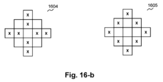
適切には、1以上の非線形関の変数を決定するため、または、1以上の非線形関の変数としての値となる隣接サンプルが、以下に示す形状に配置される:8個の隣接サンプルが非線形関数における変数を決定するため使用される、または、非線形関数における変数として使用されるとき、第1のサンプル値を交点に有する高さ5サンプル、幅5サンプルのクロス形、又は、各辺の長さが3サンプルの中空の平行四辺形、又は、12個の隣接サンプルが1以上の非線形関数における変数を決定するために使用される、または、1以上の非線形関数における変数として使用されるとき、各辺が3サンプルの長さの平行四辺形である。適切には、交点位置(及び/又は、中心位置)に第1のサンプルを持つクロス形は、次の形状の1つである:垂直および水平線の交差する“+”、または、斜め線の交差“X”(対角交差)である。適切には、前記(中空の)平行四辺形は、正方形、長方形、または菱形(diamond shape)のうちの1つである。適切には、前記(中空の)平行四辺形は、中心に位置する第1のサンプルの周りもしくは囲む。或いは、1以上の(又は前記)非線形関数における変数を判定するための使用される、もしくは、1以上の(又は前記)非線形関数における変数として使用される隣接サンプルが、中心位置にその第1のサンプルを持つ以下の形状に配置される:垂直線“|”、水平線“-”、左上から右下への斜め線“\”、または右上から左下への斜線“/”である。あるいは、1以上の(または前記)非線形関数の変数を判定するために使用される、又は、1以上の(または前記)非線形関数の変数として使用される隣接サンプルは、(中空の)多角形の形状に配置される。適切には、前記(中空の)多角形は、中心に位置する第1のサンプル位置の周りにあるか、またはそれを取り囲む。あるいは、1以上の(または前記)非線形関数における変数を決定するために使用される、または、1以上の(または前記)非線形関数における変数として使用される隣接サンプルは、前述の形状の任意の組合せの形状に配置される。適切には、フィルタ変数は、2以上の隣接するサンプル間で共有される。適切には、隣接サンプルの配置形状は、中心に関して対称性を有する。適切には、十字形、平行四辺形、または多角形の形状が、中心に関して対称性を有する。あるいは、隣接サンプルの配列の形状は、中心の周りに対称性を有さない。適切には、十字形、又は平行四辺形が中心に関して対称性を有さない。適切には、第1のサンプルおよび複数の隣接サンプル値の隣接サンプルが、以下の形状に配置される:交点に第1のサンプルを有するクロス形、或いは、平行四辺形、或いは、中空の平行四辺形である。適切には、第1のサンプル及び複数の隣接サンプル値の隣接サンプルが、平行四辺形の形状に配置される:ここで、複数の隣接サンプル値が24個の隣接サンプルの値からなる場合は各辺が4サンプルの長さを持つ、または、複数の隣接サンプル値が12個の隣接サンプルの値からなる場合は各辺が3サンプルの長さを持つ。適切には、第1のサンプルが交点(及び/又は、中心)にあるクロス形は、垂直および水平線の交差する“+”、または斜線が交差する“X”(対角線交差)のうちの1つである。適切には、前記(中空)平行四辺形は、正方形、長方形、または菱形のうちの1つである。適切には、前記(中空)平行四辺形は、中心に位置する第1のサンプルの周りにあるか、またはそれを取り囲む。あるいは、第1のサンプルおよび複数の隣接サンプル値の隣接サンプルは、第1のサンプルを中心にて次の形状に配置される:垂直線“|”、 水平線“-”、左上から右下への斜め線“\”、または右上から左下への斜め線“/”である。あるいは、第1のサンプル及び複数の隣接サンプル値の複数の隣接サンプルは、(中空の)多角形の形状に配置される。適切には、前記(中空の)多角形は、中心に位置する第1のサンプル位置の周りにあるか、またはそれを取り囲む。あるいは、第1のサンプル及び複数の隣接サンプル値の隣接サンプルは、前述の形状の任意の組み合わせの形状に配置される。適切には、フィルタ変数は、2つ以上の隣接するサンプル間で共有される。適切には、隣接サンプルの配置形状は、中心に関して対称性を有する。好適には十字形、平行四辺形、または多角形が中心に関して対称性を有する。あるいは、隣接サンプルの配置形状は、中心に関して対称性を有さない。適切には、クロス形状、平行四辺形、または多角形の形状は、中心に関して対称性を持たない。適切には、第1のサンプルおよび隣接サンプルは、ルマ成分サンプルである。あるいは、第1のサンプルおよび隣接サンプルは、がロマ成分サンプルである。適切には、(または1以上)非線形関数の変数は、第1のサンプル値をさらに含み、(または1以上)非線形関数は、第1のサンプル値と1以上の隣接サンプル値のそれぞれとの間の差に適用される。適切には(または1つ以上の)非線形関数の変数は、更に、第1のサンプル値と、1以上の隣接サンプルの位置に依存する1以上のフィルタ変数を含み、各フィルタ変数は2以上の隣接サンプルについて同じであり、(または1つ以上の)非線形関数は第1のサンプル値と、同じフィルタ変数を有する2以上の隣接サンプルの2以上の隣接サンプル値のそれぞれ1つとの間の2つ以上の差の和に適用される。適切には、(または1つ以上の)非線形関数の出力は、アダプティブループフィルタの入力(または入力パラメータ)として使用される。適切には、非線形関数は、1以上のクリッピング関数を含み、1以上のクリッピング関数の各々は、次のいずれかである:max(-b、min(b,d))、min(b、max(-b,d))、max(c-b、min(c+b,n))、min(c+b、max(c-b,n))、max(-b、min(b,d1+d2))、min(b、max(-b,d1+d2))、max(2*c-b,min(2*c+b,n1+n2))、または、min(2*c+b、max(2*c-b,n1+n2))、ここで、cは第1のサンプル値、nまたはn1またはn2は隣接サンプル値、d=n-c、d1=n1-c、d2=n2-cであり、bはクリップパラメータである。
According to a twelfth aspect of the invention, there is provided a method of controlling an adaptive loop filter for one or more image portions of an image, the method comprising: and controlling filtering of the first sample based on the value of the one or more adjacent samples, the controlling including using a non-linear function, the non-linear function being based on the one or more adjacent sample values. have variables. It is understood that neighboring samples (values) are not limited to adjacent samples (values), but also include samples (values) around or near the first sample (value). Suitably the controlling is one or more neighbors of one or more other neighboring samples not used to determine variables of the non-linear function or not used as variables of the non-linear function as input parameters of the adaptive loop filter Including using sample values. Suitably, adjacent samples used to determine or as variables in one or more (or said) non-linear functions are such that the first sample is in the shape of a cross at the intersection, or a parallelogram. placed.
Suitably adjacent samples for determining one or more non-linear relationship variables or values as one or more non-linear relationship variables are arranged in the following shape: 8 adjacent samples are non-linear A
本発明の第13の態様によれば、画像の1以上の部分を処理する方法が提供され、ここで画像部分はクロマサンプルおよびルマサンプルに関連付けれれいる。そして、この方法は、ビットストリーム、または、画像部分の第1のサンプル値とその1以上の隣接サンプル値から得た情報に基づき、第12の態様の方法を使用して制御されるフィルタを使用するかどうか、前記フィルタの使用を可とするか不可とするか、または第1のサンプル値をフィルタリングするときに前記フィルタとともに使用するためのフィルタパラメータまたはフィルタ変数のうちの少なくとも1つを決定することを含む。適切には、ビットストリームから得られる情報は、ルマ成分またはクロマ成分のうちの1つのために提供されるフラグを含み、そのフラグはその成分のために、第12の態様の方法を使用して制御されるフィルタを使用すべきか否か、または前記フィルタの使用を可とするか不可とするかの少なくとも1つを示す。適切には、フラグは、適応パラメータセット(adaptation parameter set)に提供される。好適には、ビットストリームから取得される情報は、1以上の画像部分のために提供されるフラグを含み、そのフラグは、第12の態様の手法を使用して制御されるフィルタを使用すべきか否か、または前記フィルタの使用を可とするか不可とするかのうち、少なくとも1以上の画像部分のために示す。適切には、フラグは、適応パラメータセットにて提供される。 According to a thirteenth aspect of the present invention, there is provided a method of processing one or more portions of an image, wherein the image portions are associated with chroma samples and luma samples. The method then uses a bitstream or a filter controlled using the method of the twelfth aspect based on information obtained from the first sample value and one or more adjacent sample values of the image portion. whether to enable or disable the use of the filter, or determine at least one of a filter parameter or a filter variable for use with the filter when filtering the first sample values. Including. Suitably the information obtained from the bitstream includes a flag provided for one of the luma component or the chroma component, the flag for that component using the method of the twelfth aspect. It indicates at least one of whether or not the controlled filter should be used and/or whether said filter is enabled or disabled. Suitably the flag is provided in an adaptation parameter set. Preferably, the information obtained from the bitstream includes flags provided for one or more image portions, which flags should use filters controlled using the technique of the twelfth aspect. No, or use of said filter is indicated for at least one or more image portions. Suitably a flag is provided in the adaptation parameter set.
本発明の第14の態様によれば、1以上の画像を符号化する方法が提供され、この方法は、画像の1以上の部分について、第12の態様の方法に従ってフィルタを制御すること、または第13の態様の方法に従って処理することを含む。適切には、この方法は、画像を受信すること、受信した画像を符号化し、ビットストリームを生成すること、符号化された画像を処理することをさらに含み、前記処理することは、第12の態様の方法に従って制御すること、または第13の態様の方法に従って処理することを含む。適切には、(第13の態様に依存する場合)方法は、ビットストリーム内に前記情報を提供することをさらに含む。適切には、非線形関数は、1以上のクリッピング関数を含み、(または1つまたは複数の)非線形関数の変数は、その値が(または1つまたは複数の)非線形関数内の変数として使用される1以上の複数の隣接サンプルの位置に依存する1以上のフィルタ変数をさらに含み、前記情報を提供することはビットストリーム内に1以上のクリッピングパラメータを提供することを含み、位置に関するフィルタ変数がゼロである場合、その位置における隣接サンプルの隣接サンプル値に適用されるクリッピング関数とともに使用されるクリッピングパラメータはビットストリーム内に提供されない。適切には、この方法は、複数の利用可能な関数から、非線形関数または1以上のクリッピング関数を選択すること、符号化画像を処理するときに選択された関数を使用すること、選択された関数を識別するための情報をビットストリーム内に提供することをさらに含む。 According to a fourteenth aspect of the present invention there is provided a method of encoding one or more images, comprising controlling a filter for one or more portions of the image according to the method of the twelfth aspect, or including processing according to the method of the thirteenth aspect. Suitably, the method further comprises receiving an image, encoding the received image and generating a bitstream, processing the encoded image, said processing comprising: controlling according to the method of the thirteenth aspect; or treating according to the method of the thirteenth aspect. Suitably the method (if dependent on the thirteenth aspect) further comprises providing said information in a bitstream. Suitably the non-linear function comprises one or more clipping functions and the non-linear function variable(s) whose values are used as variables in the non-linear function(s) further comprising one or more filter variables dependent on the position of one or more of the plurality of adjacent samples, wherein providing the information comprises providing one or more clipping parameters within the bitstream, wherein the filter variables with respect to position are zero; , then the clipping parameters used with the clipping function applied to the neighboring sample values of the neighboring samples at that position are not provided in the bitstream. Suitably, the method comprises: selecting a non-linear function or one or more clipping functions from a plurality of available functions; using the selected functions when processing the encoded image; providing information in the bitstream to identify the .
本発明の第15の態様によれば、1以上の画像を復号する方法が提供され、この方法は、画像の1以上の部分について、第12の態様の方法に従ってフィルタを制御すること、または第13の態様の方法に従って処理することを含む。
好適には、方法は、ビットストリームを受信すること、画像を得るために受信したビットストリームから情報を復号すること、得た画像を処理することをさらに含み、この処理することは、第12の態様の方法による制御、または第13の態様の方法による処理を含む。適切には、(第13の態様に依存する場合)方法は、ビットストリームから前記情報を得ることをさらに含む。適切には、非線形関数は1以上のクリッピング関数を含み、(または1以上の)非線形関数の変数はその値が(または1以上の)非線形関数の変数として使用される1以上の隣接サンプルの位置に依存する1以上のフィルタ変数をさらに含み、位置に関するフィルタ変数がゼロである場合、クリッピング関数はその位置における隣接サンプルの隣接サンプル値に適用されない。適切には、本方法は、ビットストリームから、複数の利用可能な関数から、非線形関数または1以上のクリッピング関数を識別するための情報を得ること、得た画像を処理するときに識別された関数を使用することをさらに含む。
According to a fifteenth aspect of the present invention, there is provided a method of decoding one or more images, comprising controlling a filter according to the method of the twelfth aspect, or processing according to the method of the thirteenth aspect.
Preferably, the method further comprises receiving a bitstream, decoding information from the received bitstream to obtain an image, and processing the obtained image, the processing comprising the steps of the twelfth Including controlling by the method of the aspect or processing by the method of the thirteenth aspect. Suitably the method (if dependent on the thirteenth aspect) further comprises obtaining said information from a bitstream. Suitably the non-linear function comprises one or more clipping functions and the (or one or more) non-linear function variables are the positions of one or more neighboring samples whose values are used as (or one or more) non-linear function variables. where the filter variable for a position is zero, the clipping function is not applied to neighboring sample values of neighboring samples at that position. Suitably, the method comprises: obtaining information from the bitstream to identify the non-linear function or one or more clipping functions from a plurality of available functions; further comprising using
本発明の第16の態様によれば、デバイスが提供される。このデバイスは、第12の態様または第13の態様の方法を実行するように構成されたコントローラと、第14の態様の方法を実行するように構成されたエンコーダ、又は、第15の態様の方法を実行するように構成されたデコーダとを備える。 According to a sixteenth aspect of the invention, a device is provided. The device comprises a controller configured to perform the method of the twelfth or thirteenth aspect and an encoder configured to perform the method of the fourteenth aspect or the method of the fifteenth aspect. and a decoder configured to perform:
本発明の第17の態様によれば、画像の1つまたは複数の部分のためのフィルタを制御するためのデバイスが提供され、デバイスは、第12の態様または第13の態様の方法を実行するように構成されたコントローラを備える。 According to a seventeenth aspect of the invention there is provided a device for controlling filters for one or more portions of an image, the device performing the method of the twelfth or thirteenth aspect a controller configured to:
本発明の第18の態様によれば、画像を符号化するデバイスが提供される。このデバイスは、第17の態様の制御装置を備える。適切には、デバイスは第14の態様の方法を実行するように構成される。 According to an eighteenth aspect of the invention, there is provided a device for encoding an image. The device comprises the controller of the seventeenth aspect. Suitably the device is configured to perform the method of the fourteenth aspect.
本発明の第19の態様によれば、画像を復号するデバイスが提供される。このデバイスは、第17の態様の制御装置を備える。適切には、このデバイスは、第15の態様の方法を実行するように構成される。 According to a nineteenth aspect of the invention, there is provided a device for decoding an image. The device comprises the controller of the seventeenth aspect. Suitably the device is configured to carry out the method of the fifteenth aspect.
本発明の第20の態様によれば、プログラムが提供される。このプログラムは、コンピュータまたはプロセッサ上で実行されるときに、コンピュータまたはプロセッサに、第1の態様、第2の態様、第3の態様、第4の態様、第5の態様、第6の態様、第7の態様、第8の態様、第12の態様、第13の態様、第14の態様、または第15の態様による方法を実行させるプログラムが提供される。 According to a twentieth aspect of the invention, a program is provided. When this program is executed on a computer or processor, it causes the computer or processor to perform the first aspect, the second aspect, the third aspect, the fourth aspect, the fifth aspect, the sixth aspect, There is provided a program causing the method according to the seventh, eighth, twelfth, thirteenth, fourteenth, or fifteenth aspects to be performed.
本発明の第21の態様によれば、第20の態様に係るコンピュータプログラムを記憶したコンピュータ読み取り可能な記憶媒体が提供される。 According to a twenty-first aspect of the present invention, there is provided a computer-readable storage medium storing a computer program according to the twentieth aspect.
本発明の第22の態様によれば、第7の態様または第14の態様による方法を使用して符号化され、ビットストリームによって表される、画像のための情報データセットを搬送する信号が提供され、この画像は再構成可能なサンプルのセットを含み、各再構成可能なサンプルはサンプル値を有する。情報データセットは、第1の再構成可能なサンプルの隣接サンプルのサンプル値に基づいて第1の再構成可能なサンプルに対するフィルタリングを制御するための制御データを含む。 According to a twenty-second aspect of the invention there is provided a signal carrying an information data set for an image encoded using a method according to the seventh or fourteenth aspect and represented by a bitstream. and the image contains a set of reconstructable samples, each reconstructable sample having a sample value. The information data set includes control data for controlling filtering for the first reconfigurable sample based on sample values of neighboring samples of the first reconfigurable sample.
本発明の前述の態様について、以下の特徴が、本発明の実施形態に従って提供されてもよい。好適には、非線形関数は、クリッピング関数、鋸歯カーネル関数、三角形カーネル関数、またはガウスカーネル関数のうちの1つまたは複数を含む。適切には、非線形関数が1以上のクリッピング関数を含み、1つ以上のクリッピング関数の各々は、max(-b、min(b,d))、min(b、max(-b,d))、max(c-b,min(c+b,d))、min(c+b,max(c-b,d))、max(-b、min(b,d1+d2))、min(b,max(-b,d1+d2))、max(2*c-b,min(2*c+b,n1+n2))、または、min(2*c+b、max(2*c-b,n1+n2))のうちの1つであり、ここで、cは第1のサンプル値であり、nまたはn1又はn2は隣接サンプル値であり、d=n-c、d1=n1-c、d2=n2-c、d2=n2-cであり、bはクリッピングパラメータである。適切には、(複数の)変数は(数学的)非線形関数の独立変数であり、非線形関数の出力はその従属変数である。適切には、隣接サンプルの位置は、第1のサンプルの位置からの相対距離または相対変位として定義される。適切には、隣接するサンプルの位置は(ラスタ)走査順序におけるその位置として定義される(適切には(ラスタ)走査順序における第1のサンプルの位置に対して)。適当には、アダプティブループフィルタは、非線形関数を使用するフィルタリングを行う。適切には、非線形関数の出力は、アダプティブループフィルタの入力(または入力パラメータ)として使用される。適切には、1以上の入力(パラメータ)にアダプティブループフィルタを適用することは、その変数として1以上の入力(パラメータ)を有する線形関数を使用することを含む。適切には、アダプティブループフィルタはVTM3.0に規定されている通りである。 For the foregoing aspects of the invention, the following features may be provided according to embodiments of the invention. Preferably, the non-linear function comprises one or more of a clipping function, a sawtooth kernel function, a triangular kernel function or a Gaussian kernel function. Suitably the non-linear function comprises one or more clipping functions, each of the one or more clipping functions being max(-b, min(b,d)), min(b, max(-b,d)) , max (c−b, min(c+b, d)), min(c+b, max(c−b, d)), max(−b, min(b, d1+d2)), min(b, max(−b , d1+d2)), max(2*c−b, min(2*c+b, n1+n2)), or min(2*c+b, max(2*c−b, n1+n2)); where c is the first sample value, n or n1 or n2 are adjacent sample values, and d=n−c, d1=n1−c, d2=n2−c, d2=n2−c. , b are clipping parameters. Suitably the variable(s) are the independent variables of the (mathematical) non-linear function and the output of the non-linear function is its dependent variable. Suitably, the positions of adjacent samples are defined as relative distances or relative displacements from the position of the first sample. Suitably the position of the neighboring sample is defined as its position in the (raster) scan order (suitably relative to the position of the first sample in the (raster) scan order). Suitably the adaptive loop filter performs filtering using a non-linear function. Suitably the output of the non-linear function is used as the input (or input parameter) of the adaptive loop filter. Suitably applying the adaptive loop filter to the one or more inputs (parameters) comprises using a linear function having the one or more inputs (parameters) as its variables. Suitably the adaptive loop filter is as specified in VTM 3.0.
本発明のさらに別の態様はコンピュータまたはプロセッサによって実行されるときに、コンピュータまたはプロセッサに前述の態様の方法のいずれかを実行させるプログラムに関する。プログラムは、それ自体で提供されてもよく、またはキャリア媒体上で、キャリア媒体によって、またはキャリア媒体内で搬送されてもよい。キャリア媒体は非一時的であってもよく、例えば、記憶媒体、特にコンピュータ可読記憶媒体であってもよい。搬送媒体はまた、一時的なもの、例えば、信号または他の伝送媒体であってもよい。信号は、インターネットを含む任意の適切なネットワークを介して送信されてもよい。 Yet another aspect of the invention relates to a program product which, when executed by a computer or processor, causes the computer or processor to perform any of the methods of the preceding aspects. The program may be provided on its own or may be carried on, by, or within a carrier medium. The carrier medium may be non-transitory, such as a storage medium, particularly a computer-readable storage medium. The carrier medium may also be transitory, such as a signal or other transmission medium. Signals may be transmitted over any suitable network, including the Internet.
本発明のさらに別の態様は、前述のデバイス態様のいずれかによるデバイスを備えるカメラに関する。本発明のさらに別の態様によれば、前述のデバイス態様のいずれかによるデバイスおよび/または前述のカメラ態様を具現化するカメラを備えるモバイルデバイスが提供される。 Yet another aspect of the invention relates to a camera comprising a device according to any of the preceding device aspects. According to yet another aspect of the invention there is provided a mobile device comprising a device according to any of the device aspects described above and/or a camera embodying the camera aspects described above.
本発明の一態様における任意の特徴は、任意の適切な組み合わせで、本発明の他の態様に適用されてもよい。特に、方法の態様は、装置の態様に適用されてもよく、逆もまた同様である。さらに、ハードウェアで実施される特徴は、ソフトウェアで実施されてもよく、その逆も可能である。ここに記載されたソフトウェアおよびハードウェアの機能についての言及は、すべて適宜解釈される必要がある。本明細書に記載されるような任意の装置特徴は、方法特徴として提供されてもよく、逆もまた同様である。本明細書で使用されるように、手段+機能特徴は、適切にプログラムされたプロセッサおよび関連するメモリなど、それらの対応する構造に関して代替的に表現されてもよい。また、本発明の任意の態様において説明され、定義された様々な特徴の特定の組合せは、独立して実装および/または供給および/または使用されることができることを理解されたい。 Any feature in one aspect of the invention may be applied to other aspects of the invention, in any appropriate combination. In particular, method aspects may be applied to apparatus aspects, and vice versa. Furthermore, features implemented in hardware may be implemented in software, and vice versa. All references to software and hardware functionality described herein should be interpreted accordingly. Any apparatus feature as described herein may be provided as a method feature, and vice versa. As used herein, means-plus-function features may alternatively be expressed in terms of their corresponding structures, such as a suitably programmed processor and associated memory. It is also to be understood that specific combinations of the various features described and defined in any aspect of the invention can be independently implemented and/or provided and/or used.
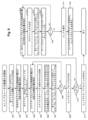
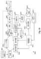
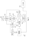
ここで、本発明の実施形態を、単なる例として、以下の図面を参照して説明する:
以下に説明する本発明の実施形態は、画像の符号化及び復号の改善に関する。 Embodiments of the invention described below relate to improved image encoding and decoding.
この明細書において、「シグナリング」がフィルタを制御するための1つ以上のパラメータに関するビットストリーム情報、例えば、モード/方式または他のフィルタ制御関連情報の使用、不使用、有効化、または無効化のためのビットストリーム情報への挿入(符号化における提供/包含/符号化)または抽出/取得(復号)を参照することができる。 As used herein, "signaling" refers to bitstream information regarding one or more parameters for controlling a filter, e.g. can refer to insertion (providing/inclusion/encoding in encoding) or extraction/retrieving (decoding) into the bitstream information for
この明細書において、「スライス」という用語は、画像部分の例として使用される(このような画像部分の他の例がタイル又はタイルグループであり、これはタイルのグループ/設定である)。本発明の実施形態はスライスの代わりに、画像部分(例えば、タイル又はタイルグループ)と、画像部分/タイル/タイルグループのヘッダ(スライスヘッダの代わりに)、画像部分/タイル/タイルグループのタイプ(スライスタイプの代わりに)、及び画像部分/タイル/タイルグループの統計値(スライス統計値の代わりに)のような適切に修正されたパラメータ/値/シンタックスとに基づいて実施されてもよいことが理解される。本発明の実施形態では、スライスヘッダまたはシーケンスパラメータセット(sequence parameter set:SPS)の代わりに、適応パラメータセット(APS)またはタイル(グループ)ヘッダを使用して、ALFパラメータ(またはALFフィルタリングを使用するための情報)をシグナリングすることもできることも理解されたい。APSがALFパラメータ(またはALFフィルタリングを使用するための情報)を信号送信するために使用される場合、スライスヘッダまたはタイルグループヘッダを使用して、たとえば、適応セット識別子(APS_id)を示すことによって、ALFパラメータ(またはALFフィルタリングを使用するための情報)を取得するためにどのAPSを使用する必要があるかを示すことができる。また、スライス、タイルグループ、タイル、コーディングツリーユニット(CTU)/最大コーディングユニット(LCU)、コーディングツリーブロック(CTB)、コーディングユニット(CU)、予測ユニット(PU)、変換ユニット(TU)、またはピクセル/サンプルのブロックのいずれかを画像部分と呼ぶことができることも理解される。 In this specification, the term "slice" is used as an example of an image portion (another example of such an image portion is a tile or tile group, which is a group/set of tiles). Instead of slices, embodiments of the present invention include image portions (e.g., tiles or tile groups), image portion/tile/tile group headers (instead of slice headers), image portion/tile/tile group types ( (instead of slice type) and appropriately modified parameters/values/syntax such as image part/tile/tile group statistics (instead of slice statistics). is understood. Embodiments of the present invention use adaptive parameter set (APS) or tile (group) headers instead of slice headers or sequence parameter sets (SPS) to use ALF parameters (or ALF filtering) It should also be understood that it is also possible to signal If APS is used to signal ALF parameters (or information for using ALF filtering), using a slice header or tile group header, e.g. by indicating an adaptation set identifier (APS_id), It can indicate which APS should be used to obtain the ALF parameters (or information to use ALF filtering). Also, slice, tile group, tile, coding tree unit (CTU)/largest coding unit (LCU), coding tree block (CTB), coding unit (CU), prediction unit (PU), transform unit (TU), or pixel It is also understood that any block of /samples can be referred to as an image portion.
フィルタまたはツールが「アクティブ」と記述される場合、フィルタ/ツールは「利用可」または「使用可能」または使用されることを示し、「非アクティブ」と記述される場合、フィルタ/ツールは「利用不可」または「使用不可」または使用されないことを示し、「クラス」は1つまたは複数の要素のグループ、グループ化、カテゴリ、または分類を指す。さらに、フラグが「アクティブ」と記述される場合、そのフラグが、関連するフィルタ/ツールが「アクティブ」であることを意味することも理解される。 When a filter or tool is described as "active", it indicates that the filter/tool is "available" or "available" or used; "disabled" or "disabled" or not used, and "class" refers to a group, grouping, category, or classification of one or more elements. Further, when a flag is described as "active," it is also understood that that flag means that the associated filter/tool is "active."
アダプティブループフィルタ(Adaptive Loop Filter)(ALF)
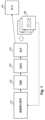
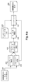
図1は、VTM-3.0の典型的な復号ループにおいてALFが行われる場合を示している。101において、画像部分(例えば、スライス)は、符号化ツリー単位(CTU:VVCにおける最大の符号化単位、典型的には128×128サンプル/ピクセルサイズ)で復号される。CTUは、特定の予測スキーム/モードを使用して符号化され、多くの場合、残差ブロックの非可逆符号化を使用して符号化される矩形ブロックまたは符号化ユニット(CU)に分割される。ブロックベースの符号化の使用により、符号化されたブロック間の境界でブロッキングアーチファクトが見えることがある。102において、復号された画像部分は次に、DBFによって処理されて、これらのアーチファクトが低減/除去される。典型的にはブロック予測のための残差(ブロック)を符号化するために、残差値はDCTのような変換を用いて(残留エネルギーを少数の係数で圧縮するために)変換され、変換された係数は符号化コストを低減するために量子化される。この量子化はしばしば、再構成されたブロック(すなわち、フレームバッファ106に記憶された参照フレーム内のブロック)に幾つかのリンギングアーチファクトを導入する。103において、DBFの出力画像部分は、次いで、SAOフィルタによって処理される。これは低計算コストでこれらのアーチファクトのいくつかを低減するのに有用である。104では、SAOフィルタの出力画像部分がALFによって処理される。ALFは、例えば、「リンギング」のようなアーチファクトをさらに低減することができる。ALFはより高次の誤差モデリング能力を有するが、より高い計算コストとなる。ALFの出力画像部分は、その後、出力(例えば、表示部または表示部と通信するための通信インターフェース)105に送られる。それは時間予測(時間予測ツールが使用される場合)のために使用することができるように、(そこに格納された参照フレームの一部として)フレームバッファ106に入れることもできる。これが、DBF、SAOフィルタ、およびALFが「ループ内」フィルタと呼ばれる理由である。エンコーダはインループフィルタのいくつかをディスエーブルにして、デコーディング時にそれらがバイパスされるようにすることができる(すなわち、フィルタリングが実行されず、ディスエーブルにされたツールに対応するステップの出力がその入力と同じである)。また、いくつかの場合、処理される画像部分は、スライスに限定されず、1つまたは複数のスライスを含むフルフレームであってもよく、スライス境界(2つ以上存在する場合)を横切ってフィルタを適用して、それらの境界上のアーチファクトを低減する可能性がある。多成分画像(例えば、YCrCbフォーマットの画像)の場合、DBF、SAOフィルタ、またはALF処理は各成分に個別に、場合によっては異なるように(例えば、他の成分に対して異なるフィルタリングパラメータを使用して)適用される。
Adaptive Loop Filter (ALF)
FIG. 1 shows the case where ALF is performed in a typical decoding loop of VTM-3.0. At 101, an image portion (eg, slice) is decoded in coding tree units (CTU: the largest coding unit in VVC, typically 128×128 samples/pixel size). A CTU is coded using a particular prediction scheme/mode and is often divided into rectangular blocks or coding units (CUs) that are coded using lossy coding of the residual block . Due to the use of block-based coding, blocking artifacts may be visible at the boundaries between coded blocks. At 102, the decoded image portion is then processed by a DBF to reduce/remove these artifacts. Typically to encode a residual (block) for block prediction, the residual values are transformed using a DCT-like transform (to compress the residual energy with a few coefficients) and transform The encoded coefficients are quantized to reduce the coding cost. This quantization often introduces some ringing artifacts into the reconstructed blocks (ie, blocks within the reference frames stored in frame buffer 106). At 103, the output image portion of the DBF is then processed by the SAO filter. This helps reduce some of these artifacts at low computational cost. At 104, the output image portion of the SAO filter is processed by ALF. ALF can further reduce artifacts such as "ringing", for example. ALF has higher order error modeling capabilities, but at a higher computational cost. The output image portion of the ALF is then sent to an output (eg, a display or a communication interface for communicating with a display) 105 . It can also be put into the frame buffer 106 (as part of the reference frames stored there) so that it can be used for temporal prediction (if a temporal prediction tool is used). This is why DBF, SAO filters and ALF are called "in-loop" filters. The encoder can disable some of the in-loop filters so that they are bypassed when decoding (i.e. no filtering is performed and the output of the step corresponding to the disabled tool is is the same as its input). Also, in some cases, the image portion to be processed is not limited to slices, but may be full frames containing one or more slices, and filter across slice boundaries (if there are more than one). may be applied to reduce artifacts on those boundaries. For multi-component images (e.g., images in YCrCb format), DBF, SAO filters, or ALF processing can be applied to each component separately and possibly differently (e.g., using different filtering parameters for other components). applicable).
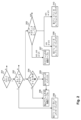
図2は、ALFのためのVTM-3.0に存在するシンタックス要素の概要を示す。シーケンスパラメータセット(SPS) は、ALF ツールがビデオシーケンス(201) に対してアクティブであるかどうかを示し、もしそうなら、スライスヘッダはALF がスライス(202) に対してアクティブかどうかを示し、ALF を制御するためのフィルタパラメータ(203 ~207) を提供する。202においてALFがアクティブであるとき、それは少なくともルマ(Luma)成分に対してアクティブであり、スライスヘッダはさらに、ALFが各クロマ(Chroma)成分に対してアクティブであるかどうかを示す(203)。 Figure 2 provides an overview of the syntax elements present in VTM-3.0 for ALF. The Sequence Parameter Set (SPS) indicates whether the ALF tool is active for the video sequence (201) and if so, the Slice Header indicates whether the ALF tool is active for the slice (202) and ALF provides filter parameters (203-207) for controlling When ALF is active at 202, it is active for at least the Luma component, and the slice header further indicates whether ALF is active for each Chroma component (203).
ALFは、1つのルマ成分上で2つ以上のフィルタを使用することができる。すなわち、異なるフィルタ構成が同じフィルタ係数(後述)を共有することができるので、フィルタ係数の複数のテーブルを使用することができる。VTM‐3.0ソフトウェアの構文要素スキームでは、これらの異なるフィルタ構成は個別に区別できず、異なる構成を持つフィルタが同じフィルタと見なされる。以下の説明では、係数の異なるテーブルを明示的に参照する場合を除いて、単一のフィルタに対する同じ参照が使用される。シンタックス要素スキームにおける単一のフィルタのこの共有は、フィルタリングされた画像上の統計が回転された直交および/またはミラー構成について同じであること、すなわち、基準サンプル構成のために設計された1つの基準フィルタが直交および/またはミラーサンプル構成をフィルタリングするために回転および/またはミラーリングされるように指定されることを考慮することによって、フィルタに割り当てられるビット数を低減する効果的な方法である。スライスヘッダは、符号化されたルマフィルタの数(204)を含む(これは一つ以上である)。 ALF can use more than one filter on one luma component. That is, multiple tables of filter coefficients can be used because different filter configurations can share the same filter coefficients (discussed below). In the syntax element scheme of the VTM-3.0 software, these different filter configurations are not individually distinguishable, and filters with different configurations are considered the same filter. In the following description, the same reference to a single filter is used, except when explicitly referring to different tables of coefficients. This sharing of a single filter in the syntax element scheme ensures that the statistics on the filtered image are the same for the rotated orthogonal and/or mirror configurations, i.e. the one designed for the reference sample configuration. Considering that the reference filter is specified to be rotated and/or mirrored to filter orthogonal and/or mirror sample configurations is an effective way to reduce the number of bits allocated to the filter. The slice header contains the number of coded luma filters (204) (which is one or more).
ルマ(Luma)サンプルをフィルタリングするとき、ALFは(隣接するサンプルの構成に従って)サンプルを25の可能なクラス(カテゴリ/分類/グループ)のうちの1つに局所的に分類(カテゴリ化)し、(その特定のクラス/カテゴリ/分類/グループに関連付けられる/割り当てられる)フィルタを選択し、それらのサンプルに局所的に適用する。ここでは、サンプルがブロック単位(典型的には4×4サンプル、例えばVTM-3.0)又はCU単位で処理されるので、「局所的に」分類、及び「局所的に」適用、という用語が使用される。選択/選択されたルマフィルタは、選択されたルマフィルタを識別するためのインデックス/情報などを使用して、ビットストリームでシグナリングされる。符号化プロセス中に使用されるルマフィルタの数が1より多い場合、スライスヘッダはこれらのルマフィルタを識別/選択するための1つまたは複数のインデックス(例えば、25個のクラスに使用される25個までのフィルタのインデックス、各インデックスは、これらのクラスのうちの1つに使用されるルマフィルタに対応する)も含む(205)。符号化処理で使用されるルマフィルタの数が1である場合、この単一のルマフィルタが全てのクラスに適用される。 When filtering Luma samples, ALF locally classifies (categorizes) the samples into one of 25 possible classes (categories/classifications/groups) (according to the composition of neighboring samples), Select a filter (associated/assigned to that particular class/category/taxonomy/group) and apply it locally to those samples. Here, the terms 'locally' classified and 'locally' applied, since the samples are processed block-wise (typically 4×4 samples, eg VTM-3.0) or CU-wise. is used. The selected/selected luma filter is signaled in the bitstream using an index/information or the like to identify the selected luma filter. If the number of luma filters used during the encoding process is greater than one, the slice header contains one or more indices (e.g., up to 25 used for 25 classes) for identifying/selecting these luma filters. , each index corresponding to a luma filter used for one of these classes (205). If the number of luma filters used in the encoding process is 1, this single luma filter is applied to all classes.
次に、スライス・ヘッダは、ルマフィルタ(206)の各々についての全てのフィルタ係数(またはフィルタ・パラメータ)(すなわち、符号化プロセス中に使用されるルマフィルタの各々についての係数テーブル)と、それに続くクロマ(Chroma)フィルタ(207)についてのフィルタ係数とを含む。VTM-3.0では、2つのクロマ成分が両方のクロマ成分に対してALFがアクティブ(すなわち、イネーブル)であるとき、同じクロマフィルタを共有することに留意されたい。 The slice header then contains all the filter coefficients (or filter parameters) for each of the luma filters (206) (i.e. the coefficient table for each of the luma filters used during the encoding process) followed by the chroma and filter coefficients for the (Chroma) filter (207). Note that in VTM-3.0, two chroma components share the same chroma filter when ALF is active (ie enabled) for both chroma components.
ALFがアクティブであるとき、ALFがアクティブである成分の各々について、フィルタリングはCTUごとにイネーブルされ得る。符号化されたビットストリームの内部では、各CTUについて、符号化されたスライスデータはALFがアクティブである各成分ごとに、そのCTUの成分(208、209、および210)上でALFがイネーブルされているかどうか、およびそのCTUのその成分のサンプルがALFを使用してフィルタリングされなければならないかどうかを示すために、1つのエントロピー符号化されたフラグを含む。このフラグは、コンテキスト適応のバイナリ算術符号化(CABAC)を使用して符号化される。 When ALF is active, filtering may be enabled per CTU for each component for which ALF is active. Within the encoded bitstream, for each CTU, the encoded slice data is processed with ALF enabled on the components (208, 209, and 210) of that CTU for each component where ALF is active. contains one entropy-encoded flag to indicate whether the component samples of the CTU should be filtered using ALF. This flag is encoded using context-adaptive binary arithmetic coding (CABAC).
VTM-3.0では、ルマフィルタ206の係数のシグナリングは以下のように実行される:
[1] “alf係数デルタフラグ(alf coefficients delta flag)”が最初にシグナリングされる。このフラグは、いくつかのフィルタをディスエーブルすることができるかどうかを示す。「alf係数デルタフラグ」がゼロであり、ルマフィルタの数が1より大きい場合、「coeffデルタ予測モードフラグ(coeff delta pred mode flag)」がシグナリングされ、フィルタ係数エンコードが予測(prediction)を使用することを示す(より詳細は後述)。
[2] VTM-3.0では、(exp-)Golomb符号化を使用してルマ係数を符号化するために、3(2 for Chroma)(exp-)Golomb構成を使用する。(exp-)Golomb符号化の唯一のパラメータは、(exp-)Golomb 次数((order)しばしば「k」と記される)である。各構成には(exp-)Golomb インデックス(index)がある。フィルタ係数の(exp-)Golomb符号化のパラメータは、(exp-)Golomb符号の「最小次数」のための可変長符号(VLC)を使用してシグナリングされ、次いで、各(exp-)Golombインデックスのために、(exp-)Golomb次数がそのインデックスおよび次のインデックスのために増加されなければならない場合(第1のインデックスのための「最小次数」で開始する)をシグナリングするためのフラグがシグナリングされる。
[3] その後、“alf係数デルタフラグ”がいくつかのフィルタが有効であることを示す場合、フィルタが無効であるかどうか(つまりコーディングされていないかどうか)を示すフラグがフィルタごとにシグナリングされる。
[4] 次に、フィルタ係数が、(exp-)Golombパラメータを記憶するテーブルから(固定テーブル内の)フィルタ係数インデックスに関連する(exp-)Golombインデックスで取られた(exp-)Golomb次数を有する(符号付き整数のための)exp-)Golombコードを使用して、各(ディスエーブルされていない)フィルタについてシグナリングされる。
In VTM-3.0, the signaling of the
[1] The "alf coefficients delta flag" is signaled first. This flag indicates whether some filters can be disabled. If the 'alf coefficient delta flag' is zero and the number of luma filters is greater than 1, then the 'coeff delta pred mode flag' is signaled and the filter coefficient encoding uses prediction. (details will be described later).
[2] VTM-3.0 uses the 3 (2 for Chroma) (exp-) Golomb construction to encode the luma coefficients using (exp-) Golomb coding. The only parameter of (exp-)Golomb coding is the (exp-)Golomb order ((order), often denoted as 'k'). Each structure has an (exp-) Golomb index. The parameters of the (exp-) Golomb coding of the filter coefficients are signaled using a variable length code (VLC) for the "minimum degree" of the (exp-) Golomb code, then each (exp-) Golomb index for the (exp-) flag to signal if the Golomb degree should be incremented for that index and the next index (starting with the "minimum degree" for the first index). be done.
[3] Then, if the "alf coefficient delta flag" indicates that some filters are valid, a flag is signaled for each filter to indicate whether the filter is invalid (i.e. not coded). be.
[4] The filter coefficients are then given the (exp-) Golomb order taken from a table storing (exp-) Golomb parameters at the (exp-) Golomb index associated with the filter coefficient index (in the fixed table). is signaled for each (not disabled) filter using an exp-) Golomb code (for signed integers).
“coeffデルタ予測モードフラグ(coeff delta pred mode flag)”がシグナリングされる場合、フィルタ係数エンコードが予測(prediction)を使用することを示す。これは、1以上のフィルタインデックス(すなわち、各フィルタを識別するインデックス)を有する「現在の」フィルタのフィルタ係数が「現在の」フィルタのフィルタ係数と以前に処理されたフィルタのフィルタ係数との間の差として符号化される(例えば、フィルタ係数予測子として以前に処理されたフィルタのフィルタ係数を使用して、すなわち、予測を使用して、フィルタ係数残差値としてエンコードされる)ことを意味する。第1のフィルタ(フィルタ・インデックス0を有する)は、予測なしに符号化される。 If the "coeff delta pred mode flag" is signaled, it indicates that the filter coefficient encoding uses prediction. This means that the filter coefficients of a "current" filter with one or more filter indices (i.e., an index that identifies each filter) are between the filter coefficients of the "current" filter and those of previously processed filters. (e.g. encoded as filter coefficient residual values using the filter coefficients of a previously processed filter as filter coefficient predictors, i.e. using prediction) do. The first filter (with filter index 0) is coded without prediction.
クロマフィルタ207の係数のシグナリングは、「alf係数デルタ・フラグ(alf coefficients delta flag)」がなく、「coeffデルタ予測モードフラグ」がなく、3つの代わりに2つの(exp-)ゴロム・インデックスがあることを除いて、ルマフィルタと同様に実行される。
The signaling of the
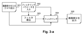
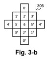
図3-aは、本発明の一実施形態によるクロマ成分をフィルタリングするためのステップを示すフローチャートであり、図3-bは、本発明の一実施形態によるクロマフィルタのためのフィルタ形状および係数配置を提供する。 FIG. 3-a is a flowchart illustrating the steps for filtering chroma components according to one embodiment of the present invention, and FIG. 3-b is a filter shape and coefficient placement for the chroma filter according to one embodiment of the present invention. I will provide a.
図3-aにおいて、ALFフィルタリングがLuma成分とChroma成分との間で異なって適用される。簡単な場合から始める場合、図3-aは、クロマ成分をフィルタリングするための主要なステップを提供する。入力画像部分301(例えば、タイル又はタイルグループ)は、フィルタリングされるべきクロマサンプルを含む。入力フィルタリングパラメータ302は、図2のALFシンタックス要素を参照して説明したALFパラメータ(例えば、“ALF係数デルタフラグ”、“coeffデルタ予測モードフラグ”、フィルタ係数、またはALFの任意の他のフラグまたはフィルタパラメータ)を含む。クロマフィルタの符号化フィルタ係数を使用し、303にて、クロマフィルタが導出/取得される。
In FIG. 3a, ALF filtering is applied differently between the Luma and Chroma components. Starting with the simple case, FIG. 3-a provides the main steps for filtering chroma components. An input image portion 301 (eg, a tile or tile group) contains chroma samples to be filtered. The
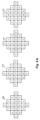
変形例では、クロマフィルタがサイズ5×5、すなわち高さ5サンプル、幅5サンプルのダイヤモンド形状/パターン/マスク/支持体を有する(図3-bの306参照)。Chromaフィルタのフィルタ係数は、「Chroma」フィルタの中心に対して対称になるように整理されている。このChroma フィルタには6つの符号化フィルタ係数があり、0 ~ 5 の番号のインデックスが付いている。この係数は図に示す対応する係数位置に配置されている。インデックス番号の上付き記号(“+”または“-”)は同じフィルタ係数を共有する異なる係数位置間で区別できるように提供され、すなわち、2つの対称な(同じフィルタ係数を共有するという意味で)隣接するものを参照するとき、i+は、(ラスタ)走査順序でフィルタリングされるサンプルの後に(すなわち、フィルタ形状/パターン/マスク/サポートの中心で)符号化/復号化/処理/記憶/アクセスされるインデックスiに対応し、i-は(ラスタ)走査順序でフィルタリングされるサンプルの前に符号化/復号化/処理/記憶/アクセスされるインデックスiを有する隣接するサンプルに対応する。クロマフィルタ形状の中心に対する7番目の係数(指数番号6を有する係数位置)は、他のフィルタ係数から推定/導出される。7番目の係数の値は、固定小数点演算(wi=インデックスiのフィルタ係数)で評価される値、1-2.Σi<6wiに等しい。すなわち、係数位置0~5に対する全てのフィルタ係数の和を、1から2倍(対称性のため)引いたものに等しい。したがって、7番目の係数を含む菱形のすべての係数の合計は、左側7ビットシフトが適用される1である(1<<7)。ここで、7は符号化されたフィルター係数のビット精度から固定小数点演算のための1を引いたものである。これが、"フィルタ係数の総数から1を引いたもの"の半分だけが、ビットストリーム内で符号化されるフィルタ係数の数である理由である。
In a variant, the chroma filter has a diamond shape/pattern/mask/support of
ALFがアクティブである(すなわち、適用される)各クロマ成分サンプルについて、ステップ304におけるフィルタリングは、出力画像部分305を得るために以下のように実行される。入力画像部分の現在のサンプルごとに、
- 現在のサンプルがCTUに属し、ALFがイネーブルされている場合、および(現在のサンプルがダイヤモンド形状の中心に配置されている)クロマフィルタのダイヤモンド形状における係数位置のためのフィルタ係数を得るために必要な現在のサンプルの隣接するサンプルが利用可能である場合(例えば、画像の境界上の境界拡張を使用して、またはスライスの境界上で利用可能である場合には隣接するスライスサンプルを使用して)、位置(x,y)における現在のサンプルI(x、y)と同じ位置における出力フィルタリングされたサンプルは、

ここで、iとjはフィルタ形状(すなわち、現在のサンプルの位置(x,y))の中心に対する2つの整数オフセット(水平および垂直)である。w(i,j)はオフセット(i,j)におけるフィルタ係数である。N=7は、オフセット(i,j)におけるフィルタ係数w(i,j)の表現において使用される実数(固定小数点表現)の小数部の整数近似のためのビット数である。I(x+i、y+j)は現在のサンプル位置(x、y)に対するオフセット(i,j)における入力サンプル値である。O(x,y)は、位置(x、y)に対する出力フィルタリングされたサンプル値である。a<<Nは、Nビット左へのビットシフトを、整数値aに適用されることを示す。これは、整数を2のN乗倍することと等価である。a>>Nは、Nビット右へのビットシフトを、整数値aに適用されることを示す。ここで、式(1)の括弧内の和の結果はほとんどの場合正であるため、Nのべき乗を2で整数除算することと等価である。負の数については、負の数が負(少なくとも-1)のままとなるように右シフトすると符号が伝播する。ALFの出力は一般に、0から2のビットの付加さの累乗から1を引いた値の間でクリップされるので、非整数部分はない。N=7は、ALF演算のためにVVCに固定された小数精度を提供するが、他の実施形態では他の値を使用することができる。右シフト>>Nを実行する前の加算(1<<(N-1))の効果は、スカラー積の固定小数点結果の丸めである。
- そうでなければ、現在のサンプル値をそれと同じ位置で(すなわち、このALFを適用せずに)出力する。
For each chroma component sample for which ALF is active (ie, applied), filtering in
- to get the filter coefficients if the current sample belongs to the CTU and ALF is enabled and for the coefficient position in the chroma filter diamond shape (where the current sample is centered in the diamond shape) If adjacent samples of the required current sample are available (e.g. using boundary extension on the boundary of the image, or using adjacent slice samples if available on the boundary of the slice) ), the output filtered sample at the same location as the current sample I(x,y) at location (x,y) is
where i and j are two integer offsets (horizontal and vertical) relative to the center of the filter shape (ie, the position (x,y) of the current sample). w(i,j) is the filter coefficient at offset (i,j). N=7 is the number of bits for the integer approximation of the fractional part of the real number (fixed point representation) used in the representation of the filter coefficients w(i,j) at offset (i,j). I(x+i,y+j) is the input sample value at offset (i,j) relative to the current sample position (x,y). O(x,y) is the output filtered sample value for location (x,y). a<<N indicates that a left bit shift of N bits is applied to the integer value a. This is equivalent to multiplying an integer by 2 to the Nth power. a>>N indicates that a right bit shift of N bits is applied to the integer value a. Here, the result of the sum in parentheses in equation (1) is almost always positive, so it is equivalent to integer division of a power of N by two. For negative numbers, a right shift propagates the sign so that the negative number remains negative (at least -1). The output of the ALF is generally clipped between 0 and 2 bits added to the
- Otherwise, output the current sample value at the same position as it (ie without applying this ALF).
本実施形態の変形例によれば、フィルタを実装しながら行われる乗算演算の回数を減らし、表記を簡略化するために、中心に関して対称なフィルタ形状を有するALFフィルタについて、式(1)を次のように再定式化することができる。

図4-aは本発明の一実施形態によるルマ成分をフィルタリングするためのステップを示すフローチャートであり、図4-bは、本発明の一実施形態によるルマフィルタのフィルタ形状、および、4つの可能な係数配列を提供する。 FIG. 4-a is a flow chart showing the steps for filtering luma components according to one embodiment of the invention, and FIG. 4-b shows the filter shape of the luma filter according to one embodiment of the invention and four possible Provide a coefficient array.
図4-aは、ルマ成分のフィルタリングプロセスの主要なステップを示す。入力画像部分401は、フィルタリングされるルマサンプルを含む。入力フィルタリングパラメータ402は、図2のALFシンタックス要素を参照して説明されたALFパラメータ(例えば、“ALF係数デルタフラグ”、“coeffデルタ予測モードフラグ”、フィルタ係数、またはALFのための任意の他のフラグまたはフィルタパラメータ)を含む。フィルタリングの前に、画像部分の内容が403で分析される。この解析の主な目的は、局所的なコンテンツの向きおよびアクティビティのレベルの決定を許可/可能にすることである(ステップ405参照)。これは、コンテンツが均質であるか、又は何らかの鋭い変化(おおよそコンテンツの強度又はコントラスト)を有するか、及びコンテンツが(例えば、エッジ又は配向されたテクスチャに基づいて)支配的な配向を有するか、及びその支配的な配向がどの配向であるかのローカル推定/評価を許可/可能にする。例えば、VTM-3.0において、この分析は、水平および垂直(すなわち、サンプルの4分の1)の2つのサンプル毎に4つの方向(水平、垂直、および2つの対角線)について計算されたラプラシアン値を使用する局所勾配分析を含む。入力画像部分のサンプルをブロック404(例えば、VTM-3.0における4×4サンプル)に分割し、分析の結果を使用することによって、ステップ405において、各ブロックは25の可能なクラスのうちの1つに分類され、各クラスはブロック内のサンプルについて計算されたラプラシアン値に従って、インデックスを使用して識別可能である(すなわち、ブロックは25のカテゴリ/分類/グループのうちの1つに分類される)。例えば、VTM-3.0では、それは16のラプラシアン値(4つのサンプル上の4つの向き)を使用することに対応する。この分類は指向性の強さのアクティビティの分割を達成し、斜め方向から水平方向と垂直方向を解離する。また、ステップ405において、各ブロックは転置インデックスに関連付けられる。この転置インデックス(例えば、“transposeIdx”)は、コンテンツの向きを完全に表す/示すために、分類に対する相補的/追加的な情報として見ることができる。4つの可能な転置インデックスがある。ブロックのクラスが、そのブロックが水平または垂直のいずれかであることを示す場合、転置インデックスは、更に、向きが北から南、東から西、西から東、または南から北であるかどうかを示す。ブロックのクラスが、そのブロックが対角線であることを示す場合、転置インデックスは、更に、向きが北西から南東、北東から南西、南西から北東、または南東から北西のいずれであるかをさらに示す。
FIG. 4a shows the main steps of the luma component filtering process.
クラスインデックスおよび転置インデックスは、所与のサンプルのブロックに対するアダプティブループフィルタパラメータとして見ることができる。ステップ406では、これらのパラメータを用いて、ブロックのサンプルの各々をフィルタリングするために使用されるルマフィルタを導出する。図2を参照して前述したように、402において、各クラスは、ルマフィルタの係数テーブルのインデックスに関連付けられる。4×4ブロックのルマフィルタを導出するために、転置インデックスは、図4-bに示される4つの形状/パターン409、410、411、または412のうちの1つを選択することを許容/可能にする。パターンは(例えば、スキャン(ning)順序に基づいて)符号化されたフィルタ係数をどのように編成してルマフィルタを構築するかを示し、これは、204~206についての説明で説明したように、ブロックのクラスに関連付けられる。ルマフィルタには、サイズ7×7 のダイヤモンド形状がある。各ルマフィルタに対して12個の符号化されたフィルタ係数(インデックス番号0~11)がある。フィルタ形の中心に対する13番目の係数(指数12)は、上述のクロマフィルタの中心係数に対するのと同じ方法で、他のフィルタ係数から推定/導出される。
The class index and transpose index can be viewed as adaptive loop filter parameters for a given block of samples. At
出力画像部分408を得るためのステップ407におけるフィルタリングは、フィルタリングがクロマフィルタによって実行されたのと同じ方法で、すなわちサンプルの各現在のブロックに対して実行されたのと同じ方法で実行され、現在のブロックに対して406において導出され/取得されたルマフィルタは現在のブロックの各現在のサンプルに適用される。
The filtering in
ルマサンプルをフィルタリングするとき、向きベース分類(クラス)および関連する転置(transposeIdx)のために、各クラスについて最適なALFフィルタ(すなわち、局所的な向き、例えば、局所的な勾配に基づいて選択される“向きベースフィルタフィルタ(orientation based filters)”、特に高い活動(例えば、高い局所的な勾配)を有するものは、向きフィルタになる傾向がある。最も低いアクティビティを有する領域、すなわち、局所勾配が比較的小さいクラスに属するブロックを有する領域では、そのような向きはあまり顕著ではなく、そのようなブロックに対する向きベースフィルタは向きフィルタではない傾向がある。 When filtering luma samples, for orientation-based classification (class) and associated transpose (transposeIdx), the optimal ALF filter for each class (i.e., selected based on local orientation, e.g., local gradient “orientation based filters”, especially those with high activity (e.g., high local gradients), tend to be orientation filters: the regions with the lowest activity, i.e., where the local gradients are In regions with blocks belonging to relatively small classes, such orientations are less pronounced, and orientation-based filters for such blocks tend not to be orientation filters.
向きベースフィルタは、エッジのシャープさにあまり影響を与えずに、エッジ周辺をフィルタリングするのに適している。以下に説明するように、クラスは、フィルタのシグナリングコストを低減するために一緒にグループ化することができる。クラスのこのグループ化を用いても、フィルタ最適化は一般に、方向付けられたフィルタを得ることにつながる。このような向きベース(ALF)フィルタでは、局所勾配が水平方向に沿っている場合、フィルタの向きは一般に垂直である(すなわち、最も高い係数(絶対値で)は一般に、中央の上下の位置にあり、一方、左側及び中央の右側の係数は一般に、ゼロに近くなる)。同様に、局所勾配が垂直方向に沿っている場合、フィルタの向きは一般に水平であり、局所勾配が、斜め方向に沿っている場合、フィルタの向きは一般に、局所勾配のその斜め方向に垂直である方向に沿っている。 Orientation-based filters are good for filtering around edges without significantly affecting edge sharpness. As described below, classes can be grouped together to reduce the signaling cost of filters. Even with this grouping of classes, filter optimization generally leads to directed filters. In such orientation-based (ALF) filters, if the local gradient is along the horizontal direction, the orientation of the filter is generally vertical (i.e., the highest coefficients (in absolute value) are generally located above and below center Yes, while the coefficients to the left and right of center are generally close to zero). Similarly, if the local gradient is along the vertical direction, the filter orientation is generally horizontal, and if the local gradient is along the diagonal direction, the filter orientation is generally perpendicular to that diagonal direction of the local gradient. along a certain direction.
VTM-3.0においてクロマサンプルをフィルタリングするとき、ルマサンプルフィルタリングとは対照的に、分類が使用されない(およびクロマはしばしば滑らかである)ので、使用されるフィルタは一般に、すべての方向に対してより応答性があり、向きフィルタではない(または無期ベースフィルタではない)。 When filtering chroma samples in VTM-3.0, in contrast to luma sample filtering, no classification is used (and chroma is often smooth), so the filters used are generally More responsive and not a directional filter (or an indefinite base filter).
図3-b及び図4-bの両方のフィルタ形状は、中心画素に関して対称である。この対称性は、VTMソフトウェアにおけるALFの設計において選択されているが、実施形態の変形形態では非対称形状も使用することができる。次に、13個の入力サンプルについて7個の係数を共有する代わりに、図3-bと同じフィルタサポート/マスクに対して最大13個の係数を使用することができた。そして、25の入力サンプルについて13の係数を共有する代わりに、図4-bと同じフィルタサポート/マスクに対して最大25の係数を使用することができた。他の変形例では、フィルサポート/マスクでさえ非対称である。変形例では、フィルタの形状/パターン/サポート/マスクがALFパラメータと共に伝送される。 The filter shapes in both Figures 3b and 4b are symmetrical about the central pixel. This symmetry was chosen in the design of the ALF in the VTM software, but asymmetric shapes can also be used in variations of the embodiment. Then, instead of sharing 7 coefficients for 13 input samples, we could use up to 13 coefficients for the same filter support/mask as in FIG. 3b. Then, instead of sharing 13 coefficients for 25 input samples, we could use up to 25 coefficients for the same filter support/mask as in FIG. 4b. In other variations even the fill support/mask is asymmetric. In a variant, the shape/pattern/support/mask of the filter is transmitted along with the ALF parameters.
他の変形では、フィルタ形状/パターン/サポート/マスクが、ダイヤモンド形状とは異なる。例えば、変形例では正方形であり、別の変形例では長方形であり、さらに別の変形例では六角形であり、別の変形例では八角形である。 In other variations the filter shape/pattern/support/mask is different than a diamond shape. For example, one variation is a square, another variation is a rectangle, another variation is a hexagon, and another variation is an octagon.
いくつかの変形例では、フィルタ形状/パターン/サポート/マスクが全てのクラス向きについて同じではない。一変形形態では、形状が水平クラス/transposeIdx向き構成のための水平矩形(例えば“-”)、垂直クラス/transposeIdx向き構成のための垂直矩形(例えば“|”)、NW-SEおよびSE-NWクラス/transposeIdx向き構成のための北-西 南-東(NW-SE、例えば“\”)矩形、NE-SWおよびSW-NEクラス/transposeIdx向き構成のための北-東 南-西(NE-SW、例えば「/」)矩形である。他の変形形態ではフィルタ形状/パターン/サポート/マスクが水平-垂直に十字(“+”)、対角十字(“X”)、垂直セグメント(“|”), 水平セグメント(“-”)、左上から右下への対角セグメント(“\”)、右上から左下への対角セグメント(“/”)、または前述のフィルタ形状/パターン/サポート/マスクの任意の組合せである。 In some variations the filter shape/pattern/support/mask is not the same for all class orientations. In one variation, the shapes are horizontal rectangle (eg "-") for horizontal class/transposeIdx orientation configuration, vertical rectangle (eg "|") for vertical class/transposeIdx orientation configuration, NW-SE and SE-NW North-West South-East (NW-SE, e.g., “\”) rectangle for class/transposeIdx orientation configuration, North-East South-West (NE-SE, eg “\”) rectangle for class/transposeIdx orientation configuration, NE-SW and SW-NE for class/transposeIdx orientation configuration SW, eg "/") is a rectangle. In other variations the filter shapes/patterns/supports/masks are horizontal-vertical crosses (“+”), diagonal crosses (“X”), vertical segments (“|”), horizontal segments (“-”), The upper left to lower right diagonal segment ("\"), the upper right to lower left diagonal segment ("/"), or any combination of the aforementioned filter shapes/patterns/supports/masks.
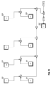
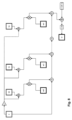
図6は、ALFにおける線形フィルタのブロック図を提供する。これは、フィルタリングが式(1)に機能的に対応し、“C”601が現在のサンプルのサンプル値に対応するI(x,y)であり、“S0”602から“Sn”603は、それぞれ隣接するサンプル値I(x+i,y+j)に対応し、ここで(i,j)≠(0,0)である。“wC”604は現在のサンプルのフィルタ係数のw(0,0)に対応し、“w0”605から“wn”606は、それぞれ位置(x+i,y+j)における隣接するサンプルのフィルタ係数のw(i,j)に対応し、ここで(i,j)≠(0,0である。“O”607はALFフィルタの出力であるO(x,y)、すなわち、現在のサンプルのフィルタリングされたサンプル値である。このプロセスは入力として、整数入力サンプル値(すなわち“C”および“S0”~“Sn”)のテーブルと、入力重みのテーブル、すなわち、固定小数点精度を有する実数の整数表現の“wC”および“w0”~“wn”(またはフィルタ係数)とを取る。このテーブルは、固定小数点精度を有する実数の整数表現で、整数入力サンプル値のテーブルと同じ数の要素を有することに留意されたい。2つのテーブルは、同じ数の要素を有し、要素ごとに乗算され、これらの乗算の結果はともに合計される(すなわち、これらの2つのテーブルの要素の線形結合が得られる)。この演算の結果は、実数の固定小数点精度近似である。この固定小数点値は整数値に丸められ、結果は1つの出力サンプル値“O”になる。 FIG. 6 provides a block diagram of a linear filter in ALF. This is because the filtering corresponds functionally to equation (1), where "C" 601 is I(x,y) corresponding to the sample value of the current sample, and "S0" 602 through "Sn" 603 are Each corresponds to an adjacent sample value I(x+i,y+j), where (i,j)≠(0,0). "wC" 604 corresponds to the current sample's filter coefficient w(0,0), and "w0" 605 through "wn" 606 respectively correspond to the adjacent sample's filter coefficients w( i,j), where (i,j)≠(0,0."O" 607 is the output of the ALF filter, O(x,y), i.e. the filtered This process takes as input a table of integer input sample values (ie, "C" and "S0" through "Sn") and a table of input weights, ie, integer representations of real numbers with fixed-point precision. Take "wC" and "w0" through "wn" (or filter coefficients) This table is an integer representation of real numbers with fixed-point precision and is expected to have the same number of elements as the table of integer input sample values. Note that the two tables have the same number of elements, are multiplied element by element, and the results of these multiplications are summed together (i.e., a linear combination of the elements of these two tables is obtained). The result of this operation is a fixed point precision approximation of a real number.This fixed point value is rounded to an integer value and the result is one output sample value "O".
エンコーダの観点から、ALFは、ウィナーフィルタ(Wiener Filter)によってインスパイアされる。ウィナーフィルタは線形フィルタ(しばしば信号/画像処理における線形畳み込みフィルタとして適用される)であり、それは、1)有限数の観測されたプロセス/変数(その入力)の線形結合である推定されたランダムプロセス/変数(その出力),2)所望のプロセス/変数(その目標、すなわちアーチファクトが発生する前の元の画像)、との間の平均二乗誤差を最小化する。信号/画像処理において、有限インパルス応答(FIR)ウィナーフィルタは、例えば、ソース分離または雑音除去における応用を有する。画像符号化の場合、対象は元の画像(圧縮/量子化によって変更される前)であり、入力は圧縮画像からのサンプルであり、フィルタを適用することによって改善したい。 From the encoder's point of view, ALF is inspired by the Wiener Filter. A Wiener filter is a linear filter (often applied as a linear convolution filter in signal/image processing), which is: 1) an estimated random process that is a linear combination of a finite number of observed processes/variables (its inputs); /variable (its output) and 2) the desired process/variable (its target, i.e. the original image before artifacts occur). In signal/image processing, finite impulse response (FIR) Wiener filters have applications, for example, in source separation or noise removal. For image coding, the target is the original image (before it is modified by compression/quantization) and the input is the samples from the compressed image, which we want to improve by applying filters.
X(これは観察されたランダムプロセスの実現の入力行列であり、各列はランダムプロセスの各1つに対して1つの実現(realization)を含む)と、y(これは観察されたランダムプロセスに対する所望のプロセスの実現を同じ列インデックスで含む出力行ベクトルである)の最小二乗解は、

ここで、ウィナーフィルタ係数は^Wに対応する。
X (which is the input matrix of observed random process realizations, each column containing one realization for each one of the random processes) and y (which is the is the output row vector containing realizations of the desired process at the same column index) is
where the Wiener filter coefficient corresponds to ^W.
なお、“実現”は、ランダム変数の観測または観測値、すなわち、実際に観測される値であることが理解される。 It should be understood that "realizations" are observations or observed values of random variables, ie values that are actually observed.
VTM-3.0 ALFエンコーダでは、FIRウィナーフィルタ(または機能的に均等の最小二乗解決策)が使用され、ALFパラメータの符号化コスト(FIRフィルタ係数を符号化するためのコストによって主に支配される)と、符号化されたALFパラメータ(FIRフィルタ)を使用して画像をフィルタリングすることによって得られる歪みゲインとの間の、レート/歪み(R/D)の妥協点を最適化する。ALFパラメータを符号化するためのレート(すなわち、符号化コスト)を懸念しない場合、そして与えられたフレームのピーク信号対ノイズ比(PSNR)を最大化することが唯一の目標とする場合(時間的影響を考慮しない場合)、ウィナーフィルタは、VTM-3.0におけるALFフィルタリング設計のための最適解を達成することを可能にするのであろう。したがって、本発明の一実施形態によるALFエンコーダは、それと共に提供される線形ALFフィルタと同じまたは類似のフィルタを使用することができる。 In the VTM-3.0 ALF encoder, an FIR Wiener filter (or functionally equivalent least-squares solution) is used and the coding cost of the ALF parameters (the cost to code the FIR filter coefficients) dominates the ) and the distortion gain obtained by filtering the image using the coded ALF parameters (FIR filter). If the rate (i.e., coding cost) for encoding the ALF parameters is not a concern, and the only goal is to maximize the peak signal-to-noise ratio (PSNR) of a given frame (temporal ), the Wiener filter will allow us to achieve the optimal solution for the ALF filtering design in VTM-3.0. Thus, an ALF encoder according to an embodiment of the invention can use the same or similar filters as the linear ALF filters provided therewith.
図9は本発明の一実施形態によるALF符号化プロセスを示すフローチャートを示し、実施形態は図6を参照して記載されたVTM-3.0のALFを修正することによって実施される。本発明の他の実施形態によれば、他のALFは、前記他の実施形態を実施するために同じ方法で修正され得ることが理解される。 FIG. 9 shows a flowchart illustrating the ALF encoding process according to one embodiment of the present invention, which is implemented by modifying the VTM-3.0 ALF described with reference to FIG. It is understood that according to other embodiments of the invention other ALFs may be modified in the same manner to implement said other embodiments.
ALF符号化プロセスは、901のルマサンプルの各4×4ブロックに対するクラスインデックスおよび転置インデックスを決定することによって開始する。 The ALF encoding process begins by determining the class index and transpose index for each 4×4 block of 901 luma samples.
次に、902において、ウィーナーフィルタを導出するために使用される統計が抽出/取得される。これらの統計量は、式(3)におけるXXTに対応する(自己(auto-)共分散統計量(covariance statistics)と、式(3)のXyT式に対応する相互共分散統計量(cross-covariance statistics)である。これらは、XXT及びXyTそれぞれをN(Xの列数、すなわち、フィルタへのサンプル数)で割ることで、(自己)共分散行列および相互共分散行列を構築/取得/推定するために使用される。これら(自己)共分散行列および相互共分散行列は、各クラス、ルマ成分サンプルの各CTU、および、各クロマ成分サンプル902の各CTUについて、構築/取得/推定される902。以下の説明では、用語“(相互)共分散行列統計”および“(相互)共分散行列”は、同じことを指すために互換的に使用される。これら2つの間の差は、“(相互)共分散行列統計”が値を累算(または合計)することによって得られるのに対し、“(相互)共分散行列”も値を累算(または合計)することによって得られるものの、その後、累算の数によって正規化される(期待値を推定するため)点であると理解される。
Next, at 902, the statistics used to derive the Wiener filter are extracted/obtained. These statistics are the auto-covariance statistics corresponding to XX T in equation (3) and the cross covariance statistics corresponding to the Xy T formula in equation (3). -covariance statistics), which construct the (auto)covariance and cross-covariance matrices by dividing XX T and Xy T respectively by N (the number of columns of X, i.e. the number of samples into the filter) These (auto)covariance matrices and cross-covariance matrices are constructed/obtained for each class, each CTU of luma component samples, and each CTU of each
所与のCTU/クラス/成分に対して、Xは以下のように得られる。フィルタの形状は対称であると考えられるので、Xにおける行の数は、フィルタのフィルタ係数の数に対応する。Xの1つの行(最後の行)は、フィルタ形状における中心サンプルの実現(フィルタ形状の中心は所与のCTU/クラス/成分に属する)を含み、一方、インデックスiを有する他の行は、フィルタ形状におけるインデックiスを有する2つの対称サンプルの合計(対称サンプルは所与のCTU/クラス/成分に属するフィルタ形状の中心の近傍である)を含む。ルマ成分のサンプルの場合、転置インデックスは図4-bの異なる形状に従ってフィルタ形状のサンプル位置を転置するためにも使用され、その結果、Xの各行iはインデックスiを有するフィルタの形状に属するサンプルのサンプル統計を含む。例えば、図4-bの形状については、Xi,jは、i<12においては、形状におけるインデックスiでの(j番目のフィルタされたサンプル)の2つの対称隣接の合計含み、i=12では、j番目のフィルタサンプルを含む。ここで、Xi,jは、マトリックスXの行i、列jの値である。 For a given CTU/class/component, X is obtained as follows. Since the shape of the filter is assumed to be symmetrical, the number of rows in X corresponds to the number of filter coefficients of the filter. One row of X (the last row) contains the realization of the central sample in the filter shape (the center of the filter shape belongs to the given CTU/class/component), while the other row with index i It contains the sum of two symmetric samples with index i in the filter shape (the symmetric sample is near the center of the filter shape belonging to a given CTU/class/component). In the case of luma component samples, the transpose index is also used to transpose the sample positions of the filter shape according to the different shapes of Fig. 4b, so that each row i of X is the sample contains sample statistics for For example, for the shape of FIG. 4b, X i,j contains the sum of the two symmetric neighbors of (the jth filtered sample) at index i in the shape, for i<12, i=12 contains the j-th filter sample. where X i,j is the value of row i, column j of matrix X;
ベクトルyは、すべてのターゲットサンプル値を含む(すなわち、yiは、その圧縮前のソース/オリジナル画像におけるj番目のサンプルの値である)。 Vector y contains all target sample values (ie y i is the value of the j th sample in the source/original image before compression).
X行列は、実際には構築/計算されない。代わりにXXTは、XiXi Tの結果を反復的に合計することで計算される。ここで、Xiは、所与のサンプル位置についてのXの第i番目の列がである。 The X matrix is not actually constructed/computed. Instead, XX T is computed by iteratively summing the results of X i X i T . where X i is the ith column of X for the given sample position.
yベクトルは、実際には構築/計算されない。代わりにXyTは、Xiyi Tの結果を反復的に合計することで計算される。ここで、yiはyの第i番目の要素であり、入力Xiを用いて、第i番目のサンプルをフィルタリングするときのターゲットサンプル値に対応する。 The y-vector is not actually constructed/computed. Instead, Xy T is computed by iteratively summing the results of X i y i T . where y i is the i th element of y and corresponds to the target sample value when filtering the i th sample using input X i .
VTM‐3.0では、ALFエンコーダはR/Dコストの低減を試みる。このR/Dコストは、レート歪妥協のラグランジュ最適化のD+λRに等しい。ここで、Dはディストーション(二次誤差)で、Rはレートであり、λは主にVTM-3.0 のエンコーダ量子化パラメータ(QP)、スライスタイプ(イントラまたはインター)、圧縮された成分のタイプ(ルマまたはクロマ) に基づいてエンコーダによって決定される。ALFエンコーダは、まず、このラグランジュR/Dコストを最小化することによってALFパラメータの最適化を試みる。 In VTM-3.0, the ALF encoder tries to reduce the R/D cost. This R/D cost is equal to D+λR of the Lagrangian optimization of the rate-distortion compromise. where D is the distortion (second-order error), R is the rate, and λ is mainly the VTM-3.0 encoder quantization parameter (QP), slice type (intra or inter), Determined by the encoder based on type (luma or chroma). The ALF encoder first tries to optimize the ALF parameters by minimizing this Lagrangian R/D cost.
ALFがルマ成分のコストを削減する場合、つまり、ALFがアクティブでないときの出力スライスの歪みが、ALFがアクティブなときの歪みとALF パラメーターをシグナルするのに必要なレートのλ倍を加えた値よりも大きい場合、エンコーダはルマ成分のアクティブなALFと判断する。次に、ルマ成分に対してアクティブである場合、クロマ成分に対するALFパラメータを最適化し、それらのクロマ成分をシグナリングするR/Dコストを改善することができるかどうかを調べようとする。これに基づいて、エンコーダは、これらの成分それぞれのALF を有効化/有効化する方が良いかどうかを判断できる。 If ALF reduces the cost of the luma component, i.e. the distortion of the output slice when ALF is not active is the distortion when ALF is active plus λ times the rate needed to signal the ALF parameters , the encoder considers an active ALF for the luma component. Next, we try to optimize the ALF parameters for the chroma components, if active for the luma components, and see if we can improve the R/D cost of signaling those chroma components. Based on this, the encoder can decide whether it is better to enable/enable ALF for each of these components.
本発明の一実施形態によれば、ALFエンコーダは、そのALFパラメータに対して同じまたは機能的に均等な最適化プロセスを実行する。このような実施形態の変形例によれば、ALFパラメータ最適化プロセスの開始時に、ALFは、すべてのCTUに対してアクティブに設定される903。共分散行列と相互共分散行列を構築するためのスライスレベルでの統計は、ALFがアクティブ/有効な各CTU の統計を集計することによって得られる。1つの行列はそのクラスに属するものとして分類された4×4サンプルブロックのすべてのサンプルについて得られた統計を使用して、ルマ成分についての各クラスについて計算され904,1つの行列はクロマについての2つのクロマ成分の統計を集約(合計)することによって計算される912。 According to one embodiment of the invention, the ALF encoder performs the same or functionally equivalent optimization process on its ALF parameters. According to a variant of such an embodiment, at the beginning of the ALF parameter optimization process, ALF is set 903 to active for all CTUs. Slice-level statistics for constructing covariance and cross-covariance matrices are obtained by ALF summarizing statistics for each active/valid CTU. One matrix is computed 904 for each class for luma components using statistics obtained for all samples in the 4x4 sample block classified as belonging to that class, one matrix for chroma It is calculated 912 by aggregating (summing) the statistics of the two chroma components.
ルマのフィルタ最適化処理は、クラスを結合/マージするための25グループのフィルタを検索する、すなわち、25個のフィルタの第1のグループ、24個のフィルタの第2のグループ、そして、1つのフィルタの最後のグループ(フィルタの可能な数ごとに1つのグループ)まで探すことで開始する905。エンコーダは各クラスに対して1 つのフィルタから始まる(そのため、合計で25 個のフィルタ)。これはそのクラスのブロックのサンプルの共分散と相互共分散から計算されるウィナーフィルタである。これは、25個のフィルタの第1のグループである。それは、フィルタを一緒にマージすることによって、すなわち、フィルタの関連するクラスを一緒にマージしてより正確にすることによって、フィルタの数を(1つずつ、そして1つだけが残るまで、全ての所望のグループを得るために)反復的に減少させようと試みる。エンコーダは、最初に2つの異なるフィルタに関連付けられたクラスに共通のフィルタを共用させる(すなわち、エンコーダは、2つのクラスをマージして1つの関連付けられたフィルタを共用する)。どのフィルタをマージすべきか(すなわち、どのクラスをマージすべきか)を決定するために、各フィルタについて共分散および相互共分散統計が決定される。エンコーダは、1つまたは複数のクラス(インデックス)に関連付けられた各フィルタについて、そのクラス(複数可)に関連付けられたサンプルのすべてのブロックに対してフィルタリングを実行するためにフィルタを使用した後に得られた総残差誤差を推定/評価する。次いで、フィルタ(およびそれらの関連するクラス)の各対について、エンコーダは、マージされた共分散および相互共分散統計を計算して、マージされたクラスのウィーナフィルタと、決定されたウィーナフィルタを用いてクラスインデックスに関連するサンプルのすべてのブロックをフィルタリングした後に得られた総残差とを決定する。次に、エンコーダは(2つのフィルタに関連付けられたクラスに関連付けられた統計から導出された)マージされたフィルタの総残差誤差と、(1つのフィルタの総残差誤差を別のフィルタと加算することによる)これら2つのフィルタの総残差誤差の合計との間の差が最小である2つのフィルタを決定し、(このマージされたフィルタが次のフィルタマージ反復の準備ができるように)これら2つのフィルタをマージする。要するに、エンコーダはarg min(Err(a+b)-Err(a)-Err(b))を最小にする一対の2つの異なるフィルタの統計をマージ(a,b)する。ここで、Err(x)は、フィルタ統計xの誤差を返し、a+bは2つのフィルタ統計a,bのマージされた統計である。 The Luma filter optimization process searches 25 groups of filters for combining/merging classes: a first group of 25 filters, a second group of 24 filters, and a Start by looking 905 to the last group of filters (one group for each possible number of filters). The encoder starts with one filter for each class (so 25 filters in total). This is a Wiener filter computed from the covariance and cross-covariance of the samples of blocks in that class. This is the first group of 25 filters. It reduces the number of filters (one by one and all Attempt to decrease iteratively (to get the desired group). The encoder first causes classes associated with two different filters to share a common filter (ie, the encoder merges the two classes to share one associated filter). Covariance and cross-covariance statistics are determined for each filter to determine which filters to merge (ie, which classes to merge). The encoder obtains, for each filter associated with one or more classes (indexes), after using the filter to perform filtering on all blocks of samples associated with that class(es). Estimate/evaluate the total residual error. Then, for each pair of filters (and their associated classes), the encoder computes the merged covariance and cross-covariance statistics using the merged class Wiener filter and the determined Wiener filter. and the total residual obtained after filtering all blocks of samples associated with the class index. The encoder then calculates the total residual error of the merged filters (derived from the statistics associated with the classes associated with the two filters) and sums the total residual error of one filter with the other Determine the two filters that have the smallest difference between the sum of the total residual errors of these two filters (by Merge these two filters. In short, the encoder merges (a,b) the statistics of a pair of two different filters that minimize arg min(Err(a+b)-Err(a)-Err(b)). where Err(x) returns the error of the filter statistic x and a+b is the merged statistic of the two filter statistics a,b.
ここまでは、倍精度浮動小数点値を用いて、統計量、フィルタ、誤差を推定している。ここで、エンコーダは、ルマフィルタを符号化するための最良のR/Dコスト妥協点を見つけようとする906。フィルタ/クラスの25個のグループが決定されると(25個のフィルタから開始して1個のフィルタまで)、各グループについて、ALFエンコーダは、各フィルタについて(整数値符号化および固定小数点精度計算のための)整数フィルタ係数を導出する。次に、異なる代替符号化方式が使用されるときの、R/Dコスト妥協に関して最良のフィルタを探索する。第1の代替は、(exp-)Golomb符号化を使用して、すべてのフィルタのすべての係数を符号化することである。第2の代替はフィルタのデルタ符号化を使用することであり、各フィルタのフィルタ係数は、((exp-)Golomb符号化を使用して)、前のフィルタのフィルタ係数との差として符号化される。第3の代替(R/D最適化)は、1つのフラグを有するいくつかのフィルタをディスエーブルすることを可能にし、ディスエーブルされていないフィルタのすべてのフィルタ係数を((exp-)Golomb符号化を使用して)符号化する。最初の2つの代替はビットレートの低減につながることができ、一方、第3の選択は、より少ないビットレートに対してより多くの歪みにつながることができる。
So far, we've used double-precision floating-point values to estimate statistics, filters, and errors. Here the encoder tries to find the best R/
エンコーダは、R/Dコストを最小限に抑えるフィルタグループおよび符号化の妥協をとる/選択する/選択する。 The encoder trades/chooses/selects filter groups and coding compromises that minimize R/D cost.
使用するルマフィルタがエンコーダによって決定/選択されると、各CTUについて、エンコーダはCTU統計量を使用して、CTUのルマサンプルをフィルタリングするR/Dコストが、同じCTUのルマサンプルをフィルタリングしないR/Dコストよりも良好であるかどうかを調べる。良好でない場合には、そのCTUのルマサンプルに対してALFがディスエーブルされる907。エンコーダはCTU(ALFが有効になっている)の共分散および相互共分散統計に関するスライス統計を更新しながら、ルマのためのルマフィルタ最適化ステップにループバックする904。例えば、VTM-3.0では、エンコーダは更に4回ループバックする。 Once the luma filter to use is determined/selected by the encoder, for each CTU, the encoder uses the CTU statistic to determine that the R/D cost of filtering the CTU's luma samples is the R/D cost of not filtering the same CTU's luma samples. Check if it is better than D-cost. If not, ALF is disabled 907 for luma samples for that CTU. The encoder loops back 904 to the luma filter optimization step for luma, updating the slice statistics for the covariance and cross-covariance statistics of the CTU (ALF enabled). For example, in VTM-3.0, the encoder loops back four more times.
ルマ成分サンプルにALFを適用するか否かの間のR/Dコスト差に応じて、エンコーダは、908にて、ALFがルマ成分に対してアクティブ/イネーブルされるべきか否かを決定する。 Depending on the R/D cost difference between applying ALF to the luma component samples or not, the encoder determines at 908 whether ALF should be activated/enabled for the luma component.
ALFがLuma成分に対してアクティブ/イネーブルされることになった場合、エンコーダは、910において、クロマ成分の処理に進む。また、ALFがルマ成分に対して非アクティブ/ディスエーブルされることになった場合、911において、ALFはアクティブ/ディスエーブルされていないとしてシグナリングされ、ALF符号化プロセスは終了する。 If ALF is to be activated/enabled for the luma component, the encoder proceeds to process the chroma component at 910 . Also, if ALF is to be deactivated/disabled for the luma component, then at 911 ALF is signaled as not active/disabled and the ALF encoding process ends.
クロマ成分のALF符号化プロセスは、ALFがスライスのすべてのCTUに対してアクティブ/イネーブルであるという条件で、2つのクロマ成分の統計を組み合わせることから開始する912。 The chroma component ALF encoding process begins by combining 912 the statistics of the two chroma components, provided that ALF is active/enabled for all CTUs of the slice.
次に、エンコーダはクロマフィルタを決定する913。エンコーダは、まず両方のクロマ成分のCTU 統計を使用して(浮動小数点)ウィナーフィルタを決定する。それは整数フィルタ係数を導出する。次に、各クロマ成分について、エンコーダはCTU統計を使用して、CTUのクロマ成分をフィルタリングするR/Dコストが、CTUのクロマ成分をフィルタリングしないR/Dコストよりも優れているかどうかを確認する。良好でない場合、ALFは、そのCTUのクロマ成分サンプルに対してディスエーブルされる914。またエンコーダが所与のクロマ成分のすべてのCTUについてALFをアクティブにすべきでない(すなわち、ディスエーブルにすべきである)と判定した場合、エンコーダはそのクロマ成分上のALFをディスエーブルにし、したがって、各CTUについて、0である「イネーブルフラグ」を符号化する必要はない915。 Next, the encoder determines 913 the chroma filters. The encoder first uses the CTU statistics of both chroma components to determine the (floating point) Wiener filter. It derives integer filter coefficients. Then, for each chroma component, the encoder uses the CTU statistics to see if the R/D cost of filtering the CTU's chroma components is better than the R/D cost of not filtering the CTU's chroma components. . If not, ALF is disabled 914 for that CTU's chroma component samples. Also, if the encoder determines that ALF should not be active (i.e., should be disabled) for all CTUs of a given chroma component, the encoder disables ALF on that chroma component, thus , for each CTU there is no need to encode 915 an "enable flag" that is 0.
エンコーダはその後、916にて、CTU(ALFが有効である)に対するクロマ成分の共分散および相互共分散統計に関するスライス統計を更新しながら、クロマフィルタ最適化ステップにループバックすることができる。例えば、VTM-3.0では、エンコーダはさらに2回ループバックする。 The encoder can then loop back to the chroma filter optimization step at 916, updating the slice statistics for the covariance and cross-covariance statistics of the chroma components for the CTU (ALF enabled). For example, in VTM-3.0, the encoder loops back two more times.
次いで、エンコーダは、917にて、決定されたALFパラメータを用いて(すなわち、ステップ913からの決定されたクロマフィルタを用いて)、本発明の実施形態によるALFを適用する。エンコーダ構成に応じて、結果として得られる画像は出力され、かつ/または参照フレームバッファに置かれる。エンコーダは最後に、最良のR/Dコストパラメータ、すなわちALFイネーブルフラグを符号化し、ALFイネーブルフラグがアクティブ/イネーブルを示す場合、決定されたALFパラメータを符号化する918。 The encoder then applies ALF according to embodiments of the present invention at 917 using the determined ALF parameters (ie, using the determined chroma filters from step 913). Depending on the encoder configuration, the resulting image is output and/or placed in a reference frame buffer. The encoder finally encodes 918 the best R/D cost parameter, the ALF enable flag, and the determined ALF parameter if the ALF enable flag indicates active/enabled.
変形例によれば、他のALFパラメータの最適化プロセスを実行して、ALFのこれらのパラメータを最適化することができることを理解されたい。 It should be appreciated that, according to variations, other ALF parameter optimization processes may be performed to optimize these parameters of the ALF.
非線形フィルタリング機能を持つALF
ステップ304および407で使用される線形フィルタリングは、非線形性を導入し、フィルタリング結果を改善する(フィルタリング品質と符号化効率との間のより良い妥協を得る)本発明の実施形態に従って修正することができる。ALFフィルタリングの目標は、符号化ツール(例えば、量子化ノイズ/エラー)によって導入されたいくつかの“ノイズ”を除去することである。このようなノイズを除去するために、信号を平滑化し、小さな局所変動を低減するために、ローパス線形フィルタがしばしば使用される。このような種類のフィルタは、フィルタリングされた出力、特にコントラストが強い領域、例えばエッジ付近にぼけを導入する可能性がある。例えば、バイラテラルフィルタのような非線形フィルタは、より効率的なノイズ除去を可能にするために開発されており、一方、エッジの周囲であっても、より少ないぼけまたはリンギング効果を導入する。そうするために、これらの非線形フィルタは、しばしば、線形フィルタのような、その局所近傍(すなわち、隣接サンプル)に基づくサンプルのフィルタリングに依存するが、非常に異なる値を有するサンプルよりも、フィルタリングされるサンプルに類似した値を有するサンプルにより多くの注意(または重み)を払う。近傍値の重み付けは、非線形関数(すなわち、非線形マッピング)を使用して実行されることが多い。これらの種類の非線形フィルタは線形フィルタよりも複雑であることが多く、それらのパラメータを最適化することは困難であることがあり、および/または、新しいALFデザインにおいてこのような種類のフィルタを使用したい場合には線形フィルタよりも柔軟性が低いことがある。
ALF with nonlinear filtering function
The linear filtering used in
本発明の一実施形態によれば、VTM-3.0(または前述の実施形態またはその変形のいずれか)のALFは、ALFの並列化可能な設計を保持する動作を含む比較的低い複雑度で非線形性を導入することによって修正される。 According to one embodiment of the present invention, the ALF of VTM-3.0 (or any of the previous embodiments or variants thereof) has relatively low complexity including operations that preserve the parallelizable design of the ALF. is corrected by introducing a nonlinearity in
VTM-3.0のALFを見ると、実数を用いて式(1)を再定式化して式を単純化することによって、我々は、

このALFにおいて、条件:


In this ALF, the conditions:
本発明の一実施形態によれば、フィルタのためにこの通常の線形公式を使用する代わりに、ALFフィルタリング処理は、ALFフィルタに非線形性を導入するように修正される。この非線形性は、オフセット(i,j)における局所勾配dを第1のパラメータとしてとり、その値が第2のパラメータb=k(i,j)に応じて変化する多変量関数K(d、b)を使用して達成される。式(6)におけるスカラー積におけるオフセット(i.j)に対する局所勾配を使用する代わりに、K(d,b)がスカラープ積において使用され、その結果、局所勾配と共に非線形に変化する出力サンプルO(x,y)が得られる。

したがって、本発明の実施形態によれば、入力サンプル値は、入力サンプル自体と、入力サンプルの近傍である入力サンプルの適応非線形変換との線形結合を使用することによってフィルタリングされる。適応非線形変換は、フィルタリングされる入力サンプルの位置と関連して、近傍の入力サンプルの相対位置に依存する。 Thus, according to embodiments of the present invention, input sample values are filtered by using a linear combination of the input samples themselves and an adaptive non-linear transformation of the input samples that are neighbors of the input samples. Adaptive nonlinear transformations depend on the relative position of neighboring input samples in relation to the position of the input sample being filtered.
このような修正ALFでは、実在するb、ゼロに等しくない現存するαという条件を満たす特定のKについて、例えばK(d,b)が、全てのdについて、dで乗算したαに等しいくなるように、線形フィルタリングを実現することができる。

したがって、bのいくつかの値(すなわち、関数K(d,b)が条件(8)を満たす)について線形関数(すなわち、線形マッピング)のように振る舞う関数K(d,b)を選択することによって、実施形態の修正ALFフィルタリング処理が、標準線形ALFを使用するのと少なくとも同程度に効率的であることが保証される(すなわち、最悪の場合、修正ALFは、VTM-3.0のALFと同じレベルの効率を達成することができる)。例えば、クリッピング関数が使用される場合、パラメータbは線形関数として動作するように、最大可能整数値に設定することができる(理想的には無限大に設定されるべきであるが、制限整数精度スキームにおける最大可能整数値を使用して同じ効果を達成することができる)。 Therefore, choosing a function K(d,b) that behaves like a linear function (i.e. linear mapping) for some values of b (i.e. the function K(d,b) satisfies condition (8)) ensures that the modified ALF filtering process of the embodiments is at least as efficient as using standard linear ALF (i.e., in the worst case, the modified ALF is as good as VTM-3.0's ALF can achieve the same level of efficiency as For example, if a clipping function is used, the parameter b can be set to the largest possible integer value so that it behaves as a linear function (ideally it should be set to infinity, but limited integer precision The same effect can be achieved using the largest possible integer value in the scheme).
本発明のいくつかの実施形態では、ALFフィルタリングは代替の公式/フィルタリング公式を使用することに留意されたい。局所勾配および追加のパラメータ/変数をとる多変量関数K(d、b)は、隣接するサンプル値、フィルタリングされるサンプル値、および追加のパラメータ/変数の3つのパラメータ/変数をとる別の多変量関数によって置き換えられる。式(4)と同様の表記を用い、条件(5)を満たしながら、式(7)を用いて再定式化する

本発明の一実施形態によれば、クロマ成分(304)およびルマ成分(407)の両方に対するフィルタリングステップは(式(1)を参照して説明したように)整数算術を使用して実施される非線形公式(好ましくは式(7)を使用するが、代わりに式(9)を使用する)でこのフィルタリングを使用するように修正される。 According to one embodiment of the invention, the filtering steps for both the chroma component (304) and the luma component (407) are performed using integer arithmetic (as described with reference to equation (1)). The non-linear formula (preferably using equation (7), but using equation (9) instead) is modified to use this filtering.
代替実施形態によれば、任意の選択が複雑さに基づく、例えば、2つのフィルタリングステップ(304)または(407)のうちの1つのみが、非線形定式化と共にフィルタを使用するように修正される。 According to an alternative embodiment, any choice is based on complexity, e.g. only one of the two filtering steps (304) or (407) is modified to use a filter with a non-linear formulation. .
いくつかの実施形態によれば、パラメータ/変数b=k(i,j)は2つ以上の次元を有し、例えば、K(d、b=(Sb,Db))=f(d、Sb,Db)は以下を用いることができる。

2つ以上の次元を有するパラメータ/変数/機能を使用することは、フィルタリングを改善することをしばしば可能にするが、フィルタパラメータをシグナリングするためにより高いコストとなる。さらに、それは、エンコーダにおいてより高い次元空間でフィルタパラメータを最適化するときに、より複雑さを招き、しばしば、デコーダにおいて機能を計算することはより複雑である(より多くのフィルタパラメータはしばしば、それらを使用するより多くの演算を意味する)。一実施形態では、bは単一の次元を有し、多くのALFアプリケーションに対して良好な妥協を達成することができる。
According to some embodiments, the parameters/variables b=k(i,j) have more than one dimension, e.g. K(d,b=(Sb,Db))=f(d,Sb , Db) can use:
Using parameters/variables/functions with more than one dimension often allows for improved filtering, but comes at a higher cost for signaling the filter parameters. Moreover, it incurs more complexity when optimizing the filter parameters in a higher dimensional space in the encoder, and it is often more complex to compute the functions in the decoder (more filter parameters are often (meaning more operations using ). In one embodiment, b has a single dimension, which can be a good compromise for many ALF applications.
いくつかの実施形態によれば、関数Kは、異なるオフセット(i.j)のための2つ以上の異なる関数を含む関数であってもよい。いくつかの実施形態では、フィルタ形状/パターン内の関数の構成/配置は、エンコーダおよびデコーダの両方で事前定義される。あるいは、関数の構成が事前定義された構成セットの中から選ぶ/選択され、選択された構成を示すインデックスが送信/シグナリングされる。他の実施形態では、関数がフィルタ形状/パターン内の各係数インデックス(中心位置を除く)についての所定の関数セットの中から選択され、そのインデックスが送信/シグナリングされる。そのような実施形態の変形では、各関数は単一の変数関数であり(すなわち、K関数もはや追加のパラメータ/変数bを有さない)、したがって、bパラメータをシグナリングする代わりに、関数インデックスがシグナリングされる。このような変形では、多変量公式、例えばK(d、b)=Kb(d)公式を使用するものと考えることができる。たとえば、bは関数セットの中から単一の変数関数Kbを選択するための整数インデックスである。 According to some embodiments, function K may be a function comprising two or more different functions for different offsets (i.j). In some embodiments, the configuration/arrangement of functions within the filter shapes/patterns is predefined at both the encoder and decoder. Alternatively, a configuration of the function is picked/selected from a predefined set of configurations and an index is sent/signaled indicating the selected configuration. In other embodiments, a function is selected from among a predefined set of functions for each coefficient index (except the center position) within the filter shape/pattern and the index is transmitted/signaled. In a variation of such an embodiment, each function is a single variable function (i.e., the K functions no longer have an additional parameter/variable b), so instead of signaling the b parameter, the function index is Signaled. Such variations can be thought of as using a multivariate formula, eg, the K(d,b)=K b (d) formula. For example, b is an integer index for selecting a single variable function K b from the set of functions.
いくつかの実施形態によれば、関数Kは、ルマフィルタとクロマフィルタとでは同じではない。いくつかの実施形態によれば、関数Kは、各ルマフィルタについて同じではない。これらの実施形態のいくつかでは、各フィルタについて、選択された関数のインデックスがスライスヘッダに提供される。 According to some embodiments, the function K is not the same for luma and chroma filters. According to some embodiments, the function K is not the same for each luma filter. In some of these embodiments, the index of the selected function is provided in the slice header for each filter.
本発明の一実施形態によれば、Kは計算が簡単になるように(過度の復号化の複雑さを導入しないように)選択される。例えば、そのような実施形態では、Kは単にクリッピング関数:
K(d,b)=max(-b,min(-b,d)). (11)
である。または同等に
K(d,b)=min(b,max(-b,d)). (12)
である。
以下に説明する代替関数のいくつかとは対照的に、クリッピング関数は局所勾配の高い値に対して消失しない(換言すれば、クリッピング関数f(x)は、xが不等性に近づくにつれてゼロに向かって収束しない)。しかし、このような単純な関数を使用した圧縮結果は、より複雑な関数を使用した場合と同じくらい効率的であり、より良好でさえあり得ることが実験的に観察されている。実際、クリッピング関数は局所勾配の高い値に対して消失するのではなく、単にそれらをクリッピングするだけで、鋭いエッジ遷移を考慮し続けることを可能にし、一方、その鋭いエッジ遷移領域の周りに存在する高い分散の影響を制限することができる。アーチファクトは鋭い遷移の周りにより強く発生するので、これは興味深い。
式(9)のフィルタリング公式を用いたこのクリッピング関数Kの等価関数K’は、
K’(n,c,b)=max(c-b,min(c+b,n)). (13)
である。または、同等に、
K’(n,c,b)=min(c+b,max(c-b,n)).
である。
クリッピング関数は、bが最大可能サンプル値(例えば、画像ビット深度の2乗)以上になるとすぐに、式(8)を満たす。
According to one embodiment of the present invention, K is chosen to be computationally straightforward (not to introduce undue decoding complexity). For example, in such an embodiment, K is simply the clipping function:
K(d,b)=max(-b,min(-b,d)). (11)
is. or equivalently K(d,b)=min(b,max(-b,d)). (12)
is.
In contrast to some of the alternative functions described below, the clipping function does not vanish for high values of the local gradient (in other words, the clipping function f(x) tends to zero as x approaches inequality). do not converge towards). However, it has been experimentally observed that compression results using such simple functions can be as efficient and even better than using more complex functions. In fact, the clipping function does not vanish for high values of local gradients, but simply clips them, allowing sharp edge transitions to continue to be considered, while existing around that sharp edge transition region. can limit the impact of high variance on This is interesting because artifacts occur more strongly around sharp transitions.
The equivalent function K' of this clipping function K using the filtering formula of equation (9) is
K'(n,c,b)=max(c-b,min(c+b,n)). (13)
is. or, equivalently,
K'(n,c,b)=min(c+b,max(c−b,n)).
is.
The clipping function satisfies equation (8) as soon as b is greater than or equal to the maximum possible sample value (eg, image bit depth squared).
以下の説明では、“クリッピングレンジ”または“クリッピングパラメータ”は、K又はK’のパラメータ/変数を参照するために使用されている。このような表現は、非線形関数パラメータを参照するための一般的な表現であると考えることができることが理解される。同様に、“クリッピング”または“クリッピング関数”は、上記またはその機能的に同等の関数K又はK’を参照または説明するために使用されてもよい。 In the following description, "clipping range" or "clipping parameter" is used to refer to K or K' parameters/variables. It is understood that such expressions can be thought of as general expressions for referring to nonlinear function parameters. Similarly, "clipping" or "clipping function" may be used to refer to or describe the above or functionally equivalent functions K or K'.
別の実施形態では、Kは別の非線形関数であってもよい。変形例では、Kは反対称関数であり、例えば、


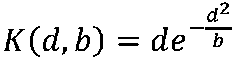
一実施形態によれば、ALFフィルタリングを実行するために必要とされるサンプルラインバッファの数を低減する(すなわち、例えばデコーダにおいてフィルタリングを実行するときに、メモリ内で処理/アクセス/保持される必要がある入力画像成分のサンプル数を低減する)ため、非線形ALFが線形ALFの代わりに使用される。 According to one embodiment, it reduces the number of sample line buffers required to perform ALF filtering (i.e. reduces the number of samples of certain input image components), non-linear ALF is used instead of linear ALF.
一変形によれば、トレードオフ/妥協として、ルマフィルタのためのフィルタ形状/パターンのサイズは、7×7ダイヤモンド形状からより小さなフィルタ形状/パターンに低減される。たとえば、ルマフィルタについて(図3-b の「クロマ」フィルタと同じ形状であるが、以前としてトランスポーズインデックスバリアントを使用する)の5×5のダイヤモンド形状が使用される。これは依然として、7×7ダイヤモンド形状のルマフィルタ(例えば、図4-bに示されるもの)を有する線形のみのALFと同様の符号化利得を達成することができるが、処理/アクセス/格納するためのサンプルの数が低減され(例えば、サンプルラインバッファの数が低減される)、また、演算の複雑さが低減され、すなわち、良好な符号化利得を達成しながら、ALFフィルタを処理するために必要とされる乗算の数が各フィルタリングされた入力サンプル当たり6だけ低減される。 According to one variant, as a tradeoff/compromise, the size of the filter shape/pattern for the luma filter is reduced from a 7×7 diamond shape to a smaller filter shape/pattern. For example, a 5×5 diamond shape for the luma filter (same shape as the “chroma” filter in FIG. 3b, but using the transpose index variant as before) is used. This can still achieve coding gains similar to a linear-only ALF with a 7×7 diamond-shaped luma filter (eg, the one shown in FIG. 4b), but the processing/access/storage is reduced (e.g., the number of sample line buffers is reduced), and the computational complexity is reduced, i.e., to process the ALF filter while achieving good coding gain. The number of multiplications required is reduced by 6 for each filtered input sample.
変形例によれば、サンプルに対してALFフィルタリングを実行するとき、非線形ALFが、線形ALFのために使用されたものであろうすべての隣接サンプルに基づいて使用される。別の変形例によれば、サンプルに対してALFフィルタリングを実行するとき、線形ALFと共に使用されたものであろう隣接サンプルのいくつかのみが非線形ALFと共に使用され、残りの隣接サンプルは線形ALFと共に使用される。さらに別の変形例によれば、サンプルに対してALFフィルタリングを実行するとき、線形ALFと共に使用されたものであろう隣接サンプルのいくつかのみが非線形ALFと共に使用され、隣接サンプルの残りも線形ALFと共に使用されない。 According to a variant, when performing ALF filtering on samples, a non-linear ALF is used based on all adjacent samples that would have been used for linear ALF. According to another variant, when performing ALF filtering on the samples, only some of the adjacent samples that would have been used with linear ALF are used with nonlinear ALF, and the remaining adjacent samples are used with linear ALF. used. According to yet another variant, when performing ALF filtering on the samples, only some of the adjacent samples that would have been used with linear ALF are used with nonlinear ALF, and the rest of the adjacent samples are also linear ALF. not used with
変形例によれば、これらのフィルタ形状/パターンの対称性を利用することによって、線形および/または非線形ALFフィルタの実施を単純化するために式(2)と同じ表記を使用して、式(4)の線形関数を次のように再定式化することができる。




最後に、式(9)の非線形関数は次のように再定式化できる。

一実施形態によれば、式(17)の関数Kを処理するための演算回数と比較して、非線形関数の処理に含まれる演算回数を減らすため、代わりに少なくとも2つの隣接差分の和に非線形性が導入される(すなわち、その変数として2つ以上の局所勾配の和を持つ非線形関数が使用されてもよい):

複雑さが低減された方程式(18)に基づく同様に導出される方程式は、2つ以上の隣接差分値(局所勾配)の和を変数として有する関数K’を用いて、別の変形例に従って使用することができることが理解される。

図7は、本発明の一実施形態による非線形フィルタのブロック図を提供する。このブロック図は、VTM-3.0内のALF内の線形フィルタの置換であり得る(またはALF内の線形フィルタに加えた、付加的な非線形フィルタであり得る)。これは、式(11)のクリッピング関数を使用して、整数固定小数点算術を用いて式(7)を実施することに対応する。“C”701はI(x,Y)に対応し、“S0”702から“Sn”703は、(i,j)≠(0,0)における、I(x+i,y+j)に対応する。“k0”704から“kn”705は、(i,j)≠(0,0)における、k(i,j)に対応し、“w0”706から“wn”707は、(i,j)≠(0,0)における、w(i,j)に対応し、そして、“O”708はO(x,y)に対応する。 FIG. 7 provides a block diagram of a nonlinear filter according to one embodiment of the invention. This block diagram could be a replacement for the linear filter in the ALF in VTM-3.0 (or it could be an additional non-linear filter in addition to the linear filter in the ALF). This corresponds to implementing equation (7) using integer fixed-point arithmetic using the clipping function of equation (11). "C" 701 corresponds to I(x,Y), and "S0" 702 to "Sn" 703 correspond to I(x+i,y+j) where (i,j)≠(0,0). "k0" 704 to "kn" 705 correspond to k(i,j), where (i,j)≠(0,0), and "w0" 706 to "wn" 707 correspond to (i,j) For .noteq.(0,0), corresponds to w(i,j) and "O" 708 corresponds to O(x,y).
図5は本発明の一実施形態による変更されたシンタックス要素の概略を伴うフローチャートであり、前述の及びそれらの関連する実施形態/変形の非線形関数(及びそのパラメータ)を実施するために使用され得るシンタックス要素の例を提供する。この実施形態では、各フィルタに対する式(7)(または(9))’の符号化フィルタ係数が、それ自体のクリッピング範囲に関連付けられ、したがって、k(i,j)はオフセット(i,j)と共に変化する異なる値を有することができる。シンタックス要素の大部分は、VTM-3.0で既に使用され、図2を参照して説明されたものと同じであり、図5の501、502、503、504、505、506、507、508、509、510は図2の201、202、203、204、205、206、207、208、209、210と同じシグナリングおよびセマンティクスを有する。新しいシンタクス要素は、各ルマフィルタ511のクリッピングパラメータ、ルマフィルタ(506)のすべてのフィルタ係数、および、例えばスライスヘッダでシグナリングされ得る各ルマフィルタ(511)のすべてのクリッピングパラメータである。このシグナリングの後に、クロマフィルタのすべてのフィルタ係数(507)およびクロマ・フィルタのすべてのクリッピング・パラメータ(512)のシグナリングが続く。
FIG. 5 is a flowchart with an overview of modified syntax elements according to one embodiment of the present invention, used to implement the nonlinear functions (and their parameters) of the foregoing and their related embodiments/variants. provides an example of the syntax elements to obtain. In this embodiment, the encoded filter coefficients of equation (7) (or (9))' for each filter are associated with their own clipping ranges, so k(i,j) is offset (i,j) can have different values that vary with . Most of the syntax elements are the same as those already used in VTM-3.0 and described with reference to FIG. 508, 509, 510 have the same signaling and semantics as 201, 202, 203, 204, 205, 206, 207, 208, 209, 210 of FIG. The new syntax elements are the clipping parameters of each
一実施形態によれば、任意のフィルタについて、シグナリングされるクリッピングパラメータの数は、シグナリングされるフィルタ係数の数と同じである。オフセット(i,j)に対するクリッピングパラメータは、同じ位置(x+i,y+j)におけるフィルタ係数に対するのと同じ方法で得られる。クロマについては図3-aのステップ303のフィルタ係数導出プロセスについて説明したのと同じ方法で(ただし、クロマクリッピングパラメータを用いて)処理され、ルマについては図4-aのステップ406のフィルタ係数導出プロセスについて説明したのと同じ方法で(ただし、ルマフィルタクリッピングパラメータを用いて)処理される。
According to one embodiment, for any filter, the number of signaled clipping parameters is the same as the number of signaled filter coefficients. The clipping parameters for offset (i,j) are obtained in the same way as for the filter coefficients at the same location (x+i,y+j). Chroma is processed in the same way as described for the filter coefficient derivation process of
代替実施形態では、フィルタごとに1つのクリッピングパラメータのみが存在し、このクリッピングパラメータはすべてのフィルタ位置(i.j)≠(0,0)について使用される。 In an alternative embodiment, there is only one clipping parameter per filter and this clipping parameter is used for all filter positions (i.j)≠(0,0).
代替実施形態では、クリッピングパラメータの数はフィルタ係数の数よりも少ない。この実施形態の変形では、これらのクリッピングパラメータがオフセット(i,j)を有するフィルタ位置のサブセット(事前定義または決定されてもよい)に使用される。他のフィルタ位置については、通常の線形フィルタリングが実行される(すなわち、換言すれば、これらの他のフィルタ位置において、Kは同一性関数であるとみなされる)か、または代替的に、事前定義されたクリッピングパラメータ値が使用される。 In alternative embodiments, the number of clipping parameters is less than the number of filter coefficients. In a variation of this embodiment, these clipping parameters are used for a subset of filter positions (which may be predefined or determined) with offsets (i,j). For the other filter positions, either normal linear filtering is performed (i.e., in these other filter positions K is taken to be the identity function) or, alternatively, the predefined specified clipping parameter value is used.
このような実施形態の変形例を、図16-aおよび図16-bを参照して説明する。これらの変形例ではクリッピング関数がフィルタ位置のサブセットに適用され、すなわち、クリッピングパターン/形状/サポート/マスクは、フィルタ形状/パターン内のフィルタ位置のサブセットのみを含み、その結果、フィルタリング処理中に、隣接するサンプル値/位置のサブセットのみがクリッピングされる(例えば、非線形関数はそのサブセットのみからのサンプル値に適用される)。クリッピング操作は、計算的に高価であり得るので、このようにフィルタリングに含まれるクリッピング操作の数を減少させることは、フィルタリングプロセスの複雑さおよび計算コストを減少させ得る。 A variation of such an embodiment is described with reference to FIGS. 16-a and 16-b. In these variants the clipping function is applied to a subset of the filter positions, i.e. the clipping pattern/shape/support/mask contains only a subset of the filter positions within the filter shape/pattern, so that during the filtering process: Only a subset of adjacent sample values/positions is clipped (eg, non-linear function is applied to sample values from only that subset). Since clipping operations can be computationally expensive, reducing the number of clipping operations involved in filtering in this way can reduce the complexity and computational cost of the filtering process.
図16-aは、低減された数のクリップ/クリッピング位置を有する7×7ダイヤモンドフィルタ形状を提供し、7×7フィルタ形状、例えば、輝度のためのALFを用いてフィルタリングを実行するときに必要とされるクリッピング動作の数を低減するためのクリップ/クリッピング位置の3つの可能な配置/例を示す。図16-aに示されるクリッピングパターンを使用することによって、クリッピング動作がすべてのフィルタ(入力)位置に適用されないため、フィルタリングを実行するためのクリッピング動作の数が減少する、すなわち、フィルタ位置のサブセット(事前に定義されてもよいし、シグナリングされてもよいし、推論されてもよい)のみがクリッピング動作に使用される(すなわち、非線形関数と共に使用される)。図16-aにおいて、クリップされたサンプル位置は、クリッピングパターン1601、1602、および1603において“X”によってマークされる。クリッピングパターン1601、1602はクリッピング回数を3分の2に減らし、クリッピングパターン1603はこの回数を1/2に減らす。これらのクリッピングパターン1601、1602および1603は、7×7ダイヤモンドフィルタ形状を使用する場合、出力の正確さとフィルタ処理に含まれる複雑さとの間の良好な妥協点を打つ。クリッピングパターン1601、1602、および1603は、ALF(すなわち、ローカルコンテンツの向きおよびアクティビティのレベルに基づく分類のために構築されたフィルタ、例えば、VTM3.0におけるルマフィルタ)の向きに基づく非線形ALFに対して良好に機能する。しかし、分類が使用されない場合、パターン1602または1603を使用することが好ましい。
FIG. 16-a provides a 7×7 diamond filter shape with a reduced number of clip/clipping positions, required when performing filtering with a 7×7 filter shape, e.g., ALF for luminance. 3 shows three possible arrangements/examples of clipping/clipping locations to reduce the number of clipping operations to be performed. By using the clipping pattern shown in FIG. 16-a, the number of clipping operations to perform filtering is reduced as the clipping operations are not applied to all filter (input) positions, i.e. a subset of filter positions (which may be predefined, signaled, or inferred) are only used for clipping operations (ie, used with non-linear functions). In FIG. 16-a, the clipped sample positions are marked by "X's" in the
他の変形例によれば、より多くの又はより少ないクリップ位置が使用されてもよいことが理解される。例えば、クリッピングパターン1601の代わりに、列全体および行全体(中心位置を除く)をクリッピングしてもよいし(すなわち、中心位置を除いて、上から下および左から右への交差)、クリッピングパターン1602の代わりに、外縁上の位置(すなわち、より大きい菱形/平行四辺形クリッピングパターン)をクリッピングしてもよい。クリップ位置の他の変形例では、クリッピングパターン/形状/支援/マスクが対角線の十字“X”(中心位置を除く)、垂直セグメント“|” (中心位置を除く)、水平セグメント“-”(中心位置を除く)、左上から右下への対角線セグメント“\”(中心位置を除く)、右上から左下への対角線セグメント「/」、または前述のクリッピングパターン/形状/サポート/マスクの任意の組合せを形成する。
It is understood that more or fewer clip locations may be used according to other variations. For example, instead of clipping
図16-bは、クリップ/クリッピング位置の数を減らした5×5ダイヤモンドフィルタ形状を提供し、5×5フィルタ形状でフィルタリングを実行するときに必要とされるクリッピング操作の数を減らすための2つのクリップ/クリッピング位置の可能な配置/構成を示す。図16-aと同様に、図16-bに示すクリッピングパターン、すなわちクリッピングパターン1604および1605を使用することによって、5×5ダイヤモンドフィルタ形状でフィルタリングする場合に、このフィルタリング処理中に含まれるクリッピング操作の数を減らすことが可能である。クリッピングパターン1604および1605は、ALF(すなわち、ローカルコンテンツの向きおよびアクティビティのレベルに基づく分類のために構築されたフィルタ、例えば、VTM3.0におけるルマフィルタ)の向き基づく、非線形ALFに対して良好に機能する。しかし、分類が使用されない場合、パターン1605を使用することが好ましい。
FIG. 16-b provides a 5×5 diamond filter shape with a reduced number of clip/clipping positions and 2 to reduce the number of clipping operations required when performing filtering with the 5×5 filter shape. 2 shows a possible arrangement/configuration of two clips/clipping positions. Similar to FIG. 16-a, the clipping operations involved during this filtering process when filtering with a 5×5 diamond filter shape by using the clipping patterns shown in FIG. 16-b, namely clipping
クリッピングパターン1602および1605は、向き(例えば、VTM-3.0における水平方向、垂直方向、または対角線方向の分類に依存するルマフィルタとは対照的に、クロマフィルタにとってより良好である)に基づく分類を使用しないフィルタに対して良好に働く。というのは、水平方向および垂直方向の近傍が、対角線方向の近傍よりも統計的に信頼性が高いため(ユークリッド距離が大きいため)である。したがって、信頼性の低い対角近傍サンプルのフィルタ位置だけにクリッピング操作を使用する方が、より信頼性の高い水平および垂直方向近傍サンプルのフィルタ位置よりも有利である。
Clipping
向きに基づくフィルタ(すなわち、分類に基づく向きに対して得たフィルタ)を使用すると、クリッピング操作は一般に、フィルタの向きに垂直なフィルタ位置でサンプリングに適用される。例えば、1601のクリッピングパターンは、対角方向を有するクラスのフィルタよりも、水平方向または垂直方向を有するクラスのフィルタの方が良好に機能する。クリッピングパターン1602は4つのクラスの向きについてもほぼ同様に機能するが、水平及び垂直の向きについてはパターン1601よりも効率的ではない。したがって、1601および1602におけるクリッピングパターンは、7×7フィルタパターンを使用するルマフィルタに対してほぼ同等に平均して実行され、1604および1605におけるクリッピングパターンは5×5フィルタパターンを使用するルマフィルタに対してほぼ同等に平均して実行される。
When using orientation-based filters (ie, filters obtained for classification-based orientation), the clipping operation is generally applied to the sampling at the filter positions perpendicular to the orientation of the filter. For example, a clipping pattern of 1601 works better for filters in classes with horizontal or vertical orientation than in filters with diagonal orientation.
変形例によれば、向きベースフィルタを改善するために、クリッピングパターンが、フィルタ方位に基づいて予め定義されたパターンから選択される。例えば、クリッピングパターン1601は、水平フィルターまたは垂直フィルター上で使用され、クリッピングパターン1602は対角フィルター上で使用される。さらに別の変形形態では、垂直フィルタのために選択されたクリッピングパターンが水平フィルタのために選択されたクリッピングパターンとは異なり(例えば、それぞれが他方の90°回転されたバージョンである)、2つの対角フィルタ配向のためのクリッピングパターンも異なる(例えば、それぞれが他方の90°回転されたバージョンである)。さらに別の変形例では、クリッピングパターンがサンプル値の各4×4ブロックに対する転置インデックス(tranposeIdx)に従って選択される。
According to a variant, a clipping pattern is selected from predefined patterns based on the filter orientation to improve the orientation-based filter. For example, clipping
変形例によれば、各フィルタに対して1つの所定のクリッピングパターンがある。別の変形例によれば、使用可能な複数(例えば、所定数)のクリッピングパターンがあり、各フィルタインデックスに対して、選択されたクリッピングパターンに対する(クリッピングパターン)インデックスが例えば、APS又はタイルグループヘッダにおいて、ALFパラメータで符号化/シグナリングされる。さらに別の変形例によれば、クリッピングパターンは、ALFパラメータを用いてシグナリングされる。例えば、クリッピングパターンのシグナリングは、フラグのシーケンスを符号化/復号することによって実行されてもよく、フィルタ(パターン)位置インデックス当たり1つのフラグ(例えば、符号化/復号されたフィルタ係数インデックスに等しい)であり、各フラグは、対応するインデックスに対してクリッピングが適用されるべきか、実際に適用されないべきかを示す。あるいはクリッピングパターンのシグナリングが、クリッピング位置インデックス自体を符号化/復号することによって、またはクリッピング位置ではないフィルタ(パターン)位置インデックスを符号化することによって実行されてもよい(好ましくはより少ない数のビットがシグナリングされることを必要とするどちらか)。 According to a variant, there is one predefined clipping pattern for each filter. According to another variant, there are multiple (e.g. a predetermined number) clipping patterns available and for each filter index the (clipping pattern) index for the selected clipping pattern is e.g. , encoded/signaled with the ALF parameters. According to yet another variant, the clipping pattern is signaled using ALF parameters. For example, signaling of the clipping pattern may be performed by encoding/decoding a sequence of flags, one flag per filter (pattern) position index (e.g. equal to encoded/decoded filter coefficient index). , where each flag indicates whether or not clipping should be applied to the corresponding index. Alternatively, the signaling of the clipping pattern may be performed by encoding/decoding the clipping position index itself, or by encoding the filter (pattern) position index that is not the clipping position (preferably with fewer bits (either requires that a signal be signaled).
変形例によれば、クリッピングパターンが使用される(所定であるか否かにかかわらず)場合、クリッピングパラメータは、クリッピング動作が適用されるフィルタ(パターン)位置についてのみシグナリングされる。 According to a variant, if a clipping pattern is used (predetermined or not), the clipping parameters are signaled only for the filter (pattern) positions where the clipping operation is applied.
いくつかの変形例では、単一命令、複数データ(SIMD)並列化実装を中断しないために、クリッピングはすべてのフィルタ位置に適用されるが、クリッピングパラメータが提供されない位置のクリッピングパラメータは線形出力(例えば、変形例では恒等関数の出力)を有するとみなされる。 In some variations, clipping is applied to all filter positions, but clipping parameters for positions where no clipping parameters are provided are linear outputs ( For example, the variant is considered to have the output of the identity function).
代替実施形態では、1つまたは複数のクリッピングパラメータが共有されるので、クリッピングパラメータの数はフィルタ係数の数よりも少ない。例えば、図3-bおよび図4-bのフィルタ形状では、いくつかの係数インデックスが同じクリッピングパラメータを共有することができる。変形例によれば、クリッピングパラメータのインデックスは、(対称性のために)形状サイズの半分から(中心係数位置のクリッピングパラメータがないために)1を引いたものに等しい数の要素を含むテーブルに示される。このテーブルは、クリッピングパラメータインデックスを各フィルタ係数に関連付けることを可能にする。変形例によれば、このテーブルは、コーデックによって固定/プリセットされる。変形例に従って、複数の固定/プリセットテーブルが定義され、テーブルからクリッピングパラメータを識別するためのインデックスが、例えばスライスヘッダ内にシグナリングされる。代替変形例では、このようなテーブルのコンテンツが、たとえばスライスヘッダーでシグナリングされ、すべてのルマフィルタで共有される。 In alternative embodiments, one or more clipping parameters are shared so that the number of clipping parameters is less than the number of filter coefficients. For example, in the filter shapes of FIGS. 3-b and 4-b, some coefficient indices can share the same clipping parameters. According to a variant, the index of the clipping parameter is in a table containing a number of elements equal to half the shape size (for symmetry) minus 1 (for no clipping parameter for the central coefficient position) shown. This table makes it possible to associate a clipping parameter index with each filter coefficient. According to a variant, this table is fixed/preset by the codec. According to a variant, multiple fixed/preset tables are defined and an index to identify the clipping parameter from the table is signaled, for example in the slice header. In an alternative variant, the content of such a table is signaled, for example, in the slice header and shared by all luma filters.
一実施形態では、クリッピングパラメータがとることができる値の数が小さくなるように制限される(エンコーダの複雑さ、及びエンコーディングコスト対小さい品質の利点を低減するために)。クリッピングパラメータに許可された値は、整数値インデックスでインデックスされる。好ましくは、増加順または減少順でインデックスが作成される。次に、これらのインデックスは、クリッピングパラメータのテーブルの各要素にマッピングすることができる。次に、クリッピングパラメータ値をシグナリングする代わりに、テーブル内の関連するクリッピングパラメータ値のインデックス(p)がシグナリングされる。テーブル内のフィルタインデックスがpである実施形態では、pの可能な値の数を減らすために中間テーブルを使用する必要はない。関数のテーブル内で利用可能な関数の数を直接減らすことが可能であり、したがって、そのサイズを減らすことが可能である。 In one embodiment, the number of values that the clipping parameter can take is constrained to be small (to reduce encoder complexity and encoding cost versus small quality advantage). The allowed values for the clipping parameter are indexed by integer indices. Preferably, the indexes are created in ascending or descending order. These indices can then be mapped to each element of the table of clipping parameters. Then, instead of signaling the clipping parameter value, the index (p) of the relevant clipping parameter value in the table is signaled. In embodiments where the filter index in the table is p, there is no need to use an intermediate table to reduce the number of possible values of p. It is possible to directly reduce the number of functions available in the table of functions, thus reducing its size.
一実施形態では、クリッピングパラメータ値が2の累乗:2pに制限される。次に、符号化されるものがpとなる。pの最大値は、入力画像のビット深度Bdである(同じ結果を提供するので、より高い値は必要ではない)。代替実施形態では、pの代わりに、符号化されるものはBd-pである。別の実施形態では、pの範囲が、pminとpmax間にあるように制限される。例えば、pmin=3、Pmax=Bd-1である。その後、p-pmin又はpmax-pがシグナリングすることができる。 In one embodiment, clipping parameter values are limited to powers of two: 2p . Then what is encoded becomes p. The maximum value of p is the bit depth B d of the input image (higher values are not necessary as they provide the same result). In an alternative embodiment, instead of p, what is encoded is B d -p. In another embodiment, the range of p is restricted to be between p min and p max . For example, p min =3 and P max =B d -1. Then pp min or p max -p can be signaled.
一実施形態では、クロマフィルタの許可/許容/利用可能なクリッピングパラメータ値は、ルマフィルタの値と同じではない。 In one embodiment, the allowed/accepted/available clipping parameter values for the chroma filter are not the same as the values for the luma filter.
一実施形態によれば、スライス内のクリッピングパラメータに使用される、テーブルpmin内の最小インデックスおよびテーブルPmax内の最大インデックスはスライスヘッダ内に提供され、その結果、可能なクリッピングパラメータ値の数はそれらをシグナリングするときに制限/制限され得る。一実施形態によれば、pmin及びpmaxは、ルマフィルタおよびクロマフィルタによって共有される。代替の実施形態では、pmin及びpmaxは、ルマについてのみ提供され、クロマインデックスは限定されない。別の代替実施形態では、pmin及びpmaxは、ルマ用およびクロマ用のスライスヘッダに提供される。 According to one embodiment, the minimum index in table p min and the maximum index in table P max to be used for clipping parameters within a slice are provided in the slice header, resulting in the number of possible clipping parameter values may be restricted/restricted when signaling them. According to one embodiment, p min and p max are shared by luma and chroma filters. In an alternative embodiment, p min and p max are provided only for luma and the chroma index is not limited. In another alternative embodiment, p min and p max are provided in slice headers for luma and chroma.
代替の実施形態によれば、許可されたクリッピングパラメータ値の1つのテーブルが、ルマおよびクロマの両成分についてスライスヘッダ内でシグナリングされるか、あるいは、2つのテーブル、すなわち、1つはルマ、1つはクロマのテーブルについてシグナリングされる。 According to alternative embodiments, one table of allowed clipping parameter values is signaled in the slice header for both luma and chroma components, or two tables, one for luma, one for luma, one for luma, and one for luma. One is signaled about the chroma table.
本発明の一実施形態では、クリッピングパラメータ511および512は、スライス・ヘッダ内でシグナリングされない。その代わりに、そのクリッピングパラメータは、フィルタリングされたサンプルに信号を送るために使用された量子化パラメータ(QP)を使用し、フィルタのクラスインデックスに基づいて、エンコーダ/デコーダにて決定される。
In one embodiment of the invention, clipping
代替実施形態では、クリッピングパラメータ511および512は、スライスヘッダ内でシグナリングされる。しかし、フィルタリング処理では、それらは直接使用されない。その代わり、フィルタリングされたサンプルに使用された量子化パラメータ(QP) に応じて、クリッピングパラメータがスケーリングされる。
In an alternative embodiment, clipping
一実施形態では、ルマフィルタのクリッピングパラメータは、各フィルタに提供されない。クリッピングパラメータの2 つのテーブルのみが、全てのルマスフィルタで共有され、スライスヘッダ内にシグナリングされる。1つのテーブルは水平/垂直クラス用であり、他のテーブルは対角クラス用である。各クラスのクリッピングパラメータは、図4-bの係数配列を使用し、クラスのアクティビティのレベルから決定された固定値に応じてクリッピングパラメータをスケーリング(すなわち、乗算)することによって、クラスの向きに従ってこれら2つのテーブルから導出される。スケーリングは、4×4ブロックを分類するときにアクティビティのレベルを考慮に入れる。例えば、高レベルのアクティビティの領域(例えば、エッジの近く)については、低レベルのアクティビティの領域(例えば、均一な領域)と比較した場合に、より高いクリッピング値を使用することができる。 In one embodiment, clipping parameters for luma filters are not provided for each filter. Only two tables of clipping parameters are shared by all lumas filters and signaled in the slice header. One table is for the horizontal/vertical class and the other table is for the diagonal class. The clipping parameters for each class are calculated according to the orientation of the class by using the coefficient array of Figure 4b and scaling (i.e., multiplying) the clipping parameters according to a fixed value determined from the level of class activity. Derived from two tables. Scaling takes into account the level of activity when sorting 4x4 blocks. For example, higher clipping values can be used for regions of high level activity (eg, near edges) when compared to regions of low level activity (eg, uniform regions).
一実施形態では、スライス・ヘッダ内の1ビットが、各フィルタの各フィルタクリッピングインデックスに対してクリッピングがイネーブル/ディスエーブルされることをシグナルする。クリッピングパラメータ毎に1つの許容クリッピング値しかない実施形態では、ビットがクリッピングがアクティブであることを示す場合、クリッピング値が使用される(すなわち、クリッピングパラメータ値に対して他の何もシグナリングされない)。あるいは複数のクリッピング値が許可される場合、1つのクリッピングインデックスのビットがそのフィルタクリッピングインデックスについてクリッピングが無効であることを示す場合は、クリッピング値はシグナリングされないが、他の場合、クリッピング値はシグナリングされる。 In one embodiment, one bit in the slice header signals that clipping is enabled/disabled for each filter clipping index of each filter. In embodiments with only one allowed clipping value per clipping parameter, if the bit indicates that clipping is active, the clipping value is used (ie, nothing else is signaled for the clipping parameter value). Alternatively, if multiple clipping values are allowed, if the bit of one clipping index indicates that clipping is disabled for that filter clipping index, then no clipping value is signaled, otherwise the clipping value is signaled. be.
ここで、フィルタクリッピングインデックスは、フィルタ形状におけるフィルタ係数インデックスに関連するクリッピングパラメータのインデックスに対応する。 Here, the filter clipping index corresponds to the index of the clipping parameter associated with the filter coefficient index in the filter shape.
一実施形態では、許容されるクリッピング値は、スライスタイプ(例えば、INTRA、B、又はPとすることができる)に依存する。 In one embodiment, the allowed clipping value depends on the slice type (eg, it can be INTRA, B, or P).
実施形態の変形例では、許容されるクリッピング値がBまたはPスライスにおけるルマについては{ 6、32、181、1024 }、BまたはP_sliceにおけるクロマについては{ 4、25、161、1024 }、INTRAスライスにおけるルマについては{ 10、102、1024 }、および/またはINTRAスライスにおけるクロマについては{ 4、24、1024 }である。したがって、任意のクリッピングパラメータは、これらのセットのうちの1つに属する値をとることができる(したがって、スライスタイプおよびフィルタリングされた成分に属する)。また、セット内のその値のインデックスは、クリッピングパラメータごとに、フィルタごとにスライスヘッダにエンコードされる。 In a variant of the embodiment, the allowed clipping values are { 6, 32, 181, 1024 } for luma in B or P slices, { 4, 25, 161, 1024 } for chroma in B or P_slices, INTRA slices { 10, 102, 1024 } for luma in INTRA slices and/or { 4, 24, 1024 } for chroma in INTRA slices. Any clipping parameter can therefore take on values that belong to one of these sets (and thus belong to the slice type and filtered component). Also, the index of that value in the set is encoded in the slice header for each filter, for each clipping parameter.
変形例では、許容されるクリッピング値のテーブルは次のように定義される:

変形例では、許容されるクリッピング値のテーブルは次のように定義される:

一実施形態では、許容されるクリッピング値は、各フィルタクリッピングインデックスについて同じではない。 In one embodiment, the allowed clipping values are not the same for each filter clipping index.
差分値にクリッピング機能を使用する変形例では、すなわち、式(11)または式(12)の関数Kを隣接サンプル値と中心値との間の差に適用する場合は、最大許容クリッピング値は、クリッピングの出力におけるビット数が低減されるように定義される。これにより、これらの変形例に従ってフィルタリングを実行するハードウェア実装で処理する必要があるビット数を制限できる。このように、これにより、例えば、チップ内の論理ゲート/トランジスタの数を減らすことができる。乗算演算子の入力端におけるビット数を減らすことは、乗算が多くの論理ゲートを必要とするので、特に興味深い。例えば、最大許容クリッピング値を、2のサンプルビット深度から1を引いた累乗から1を引いた値(すなわち、2^(ビット深度-1)-1?1に等しい最大クリッピング)に設定することにより、クリッピングの出力端で、したがって乗算演算子の入力端で、最大ビット数を1だけ減らすことができる。そして、サンプルビット深度マイナス2(すなわち、2^(ビット深度-2)-1に等しい最大クリッピング)を使用することにより、最大ビット数を2だけ減少させることができる。 In a variant using a clipping function on the difference values, i.e. when applying the function K of equation (11) or equation (12) to the difference between adjacent sample values and the central value, the maximum allowable clipping value is It is defined such that the number of bits in the output of clipping is reduced. This can limit the number of bits that need to be processed in a hardware implementation that performs filtering according to these variants. As such, this can, for example, reduce the number of logic gates/transistors in the chip. Reducing the number of bits at the input of the multiplication operator is of particular interest since multiplication requires many logic gates. For example, by setting the maximum allowable clipping value to the sample bit depth of 2 minus 1 to the power of 1 (i.e., maximum clipping equal to 2^(bit depth - 1) - 1 - 1). , at the output of clipping and thus at the input of the multiplication operator, the maximum number of bits can be reduced by one. The maximum number of bits can then be reduced by 2 by using a sample bit depth minus 2 (ie, maximum clipping equal to 2^(bit depth - 2) - 1).
APSを使用する実施形態では、イントラスライスとインタースライス(又はイントラ及びインターピクチャ/画像部分/タイルグループ)との間の区別が、APSがイントラ及びインタースライス/ピクチャ/タイルグループ/画像部分によって共有されるので、クリッピング値導出中に可能でないことがある。その場合、許容されるクリッピング値の所定のテーブルは、もはやスライス/画像部分/タイルグループタイプに依存することができない。したがって、1つのデフォルトクリッピング値テーブルは、すべてのスライス/ピクチャ/タイルグループ/画像部分タイプによって共有される。変形例では、例えば、複雑さを減らすことを考慮して、クリッピング値がデフォルトクリッピング値テーブルからのクリッピング値のサブセットに制限されるかどうかをエンコーダに決定させる(次いで、デコーダにシグナリングする)。 In embodiments using APS, the distinction between intra-slices and inter-slices (or intra- and inter-pictures/image portions/tile-groups) is such that APS is shared by intra- and inter-slices/pictures/tile-groups/image portions. so it may not be possible during clipping value derivation. In that case, a given table of allowed clipping values can no longer depend on the slice/image portion/tile group type. Therefore, one default clipping value table is shared by all slices/pictures/tile groups/image portion types. A variant allows the encoder to decide (and then signals to the decoder) whether the clipping values are restricted to a subset of clipping values from the default clipping value table, for example in consideration of reducing complexity.
変形例では、使用可能なクリッピング値のクリッピング値テーブルが、ALFパラメータと共にAPSにおいてシグナリングされる。したがって、エンコーダ(およびデコーダ)は、任意のクリッピング値を使用し、使用されたクリッピング値をそれ自体のクリッピング値テーブルとともにシグナリングすることができる。 In a variant, a clipping value table of possible clipping values is signaled in the APS together with the ALF parameter. Thus, the encoder (and decoder) can use any clipping value and signal the used clipping value along with its own clipping value table.
変形例では、複数のデフォルトクリッピング値テーブルがある。たとえば、1つはインタースライスに使用され、もう1つはイントラスライスに使用される。使用されたテーブルを識別するための情報、例えば、使用されたテーブルのインデックスは、ALFパラメータと共にAPSに提供される。変形例では、デフォルトのクリッピング値テーブルはルマとクロマで異なる。 In a variant, there are multiple default clipping value tables. For example, one is used for interslices and the other for intraslices. Information identifying the used table, eg, the index of the used table, is provided to the APS along with the ALF parameter. In a variant, the default clipping value table is different for luma and chroma.
一実施形態では、フィルタの出力値も、入力サンプル値および追加のクリッピングパラメータ(クリッピングパラメータのテーブルに追加することができる)に応じてクリッピングされる。 In one embodiment, the output values of the filter are also clipped depending on the input sample values and additional clipping parameters (which can be added to a table of clipping parameters).
一実施形態によれば、ALFアクティブフラグに加えて、NLALF(非線形(NonLinear)ALF)アクティブフラグが非線形ALFが、アクティブ/使用/イネーブルであることを示すために、例えば、SPS内のシーケンスレベルに、または代替として、例えば、ピクチャヘッダ内のフレームレベルに置かれる。このフラグがアクティブである(すなわち、非線形ALFがアクティブであることを示す)場合、ALFのシンタックス要素は、非線形フィルタ、例えば図5のフィルタパラメータを含む。フラグが非アクティブである(すなわち、非線形ALFがアクティブではあることを示さない)場合、ALFのシンタックス要素は、線形フィルタ、例えば図2のフィルタパラメータのみを含む。 According to one embodiment, in addition to the ALF active flag, a NLALF (NonLinear ALF) active flag is added to indicate that the nonlinear ALF is active/used/enabled, e.g. , or alternatively placed at the frame level, eg, in the picture header. If this flag is active (ie, indicates that the non-linear ALF is active), the ALF syntax element includes the non-linear filter, eg, filter parameters of FIG. If the flag is inactive (ie, does not indicate that the non-linear ALF is active), then the ALF syntax element contains only the linear filter, eg, filter parameters of FIG.
一実施形態によれば、ALFフラグがスライスヘッダにおいてアクティブである場合、NLALFアクティブフラグがスライスヘッダに置かれる。このNLALFフラグがアクティブである場合、各ルマフィルタ構文要素511のクリッピングパラメータおよびクロマフィルタ512のクリッピングパラメータは、スライスヘッダ内に存在する。このNLALFフラグが非アクティブである場合、シンタックス要素511および512は、スライスヘッダに存在せず、ALFは通常の線形フィルタリングを使用する。
According to one embodiment, an NLALF active flag is placed in the slice header if the ALF flag is active in the slice header. When this NLALF flag is active, the clipping parameters of each luma
代替実施形態によれば、別個のNLALFアクティブフラグが各成分タイプであるルマおよびクロマに対して提供され、これらのフラグの一方または両方が非線形ALFが特定の成分のサンプル上で使用されるべきかどうかを示すために使用される(例えば、それらは、シーケンスレベルで、またはスライスヘッダ内など、NLALFアクティブフラグと同じ場所に提供される)。変形例では、非線形ALFがルマ上で使用され、線形ALFがクロマ上で使用される。代替的な変形例では、非線形ALFがクロマ上で使用され、線形ALFがルマ上で使用される。 According to an alternative embodiment, separate NLALF active flags are provided for each component type, luma and chroma, and one or both of these flags indicate whether non-linear ALF should be used on the samples of a particular component. (e.g. they are provided at the sequence level or in the same place as the NLALF active flag, such as in the slice header). In a variant, non-linear ALF is used on luma and linear ALF on chroma. In an alternative variant, nonlinear ALF is used on chroma and linear ALF is used on luma.
変形例では、NLALFルマアクティブフラグとNLALFクロマアクティブフラグがスライスヘッダに提供される。NLALFルマアクティブフラグは、非線形アダプティブループフィルタがルマ成分で使用されるかどうか、したがって非線形ALFのクリッピングパラメータが各ルマフィルタについてシグナリングされるかどうかを示す。NLALFクロマアクティブフラグは、非線形アダプティブループフィルタがクロマ成分に使用されるかどうか、したがって非線形ALFのクリッピングパラメータがクロマフィルタのためにシグナリングされるかどうかを示す。 In a variant, an NLALF luma active flag and an NLALF chroma active flag are provided in the slice header. The NLALF luma active flag indicates whether a non-linear adaptive loop filter is used in the luma component, and thus whether a non-linear ALF clipping parameter is signaled for each luma filter. The NLALF chroma active flag indicates whether a non-linear adaptive loop filter is used for the chroma component, and thus whether non-linear ALF clipping parameters are signaled for the chroma filter.
変形例では、NLALFクロマアクティブフラグはシグナリングされないが、NLALFルマアクティブフラグがゼロに等しい場合、ゼロに等しいと推測され、その結果、非線形ALFはクロマのみでは使用できない。 In a variant, the NLALF chroma active flag is not signaled, but if the NLALF luma active flag is equal to zero, it is assumed to be equal to zero, so that non-linear ALF cannot be used with chroma alone.
変形例では、非線形ALFは常にルマに使用され(デフォルトではNLALFルマアクティブフラグは使用されない、または、対応するデフォルト値であると仮定されてもよい)、NLALFクロマアクティブフラグは非線形ALFまたは線形ALFがクロマに使用されるかどうかを示すために使用される。別の変形例では、線形ALFが(デフォルトではNLALFルマアクティブフラグは使用されない、または対応するデフォルト値であると仮定される)ルマに常に使用され、NLALFクロマアクティブフラグが非線形ALFまたは線形ALFがクロマに使用されるかどうかを示すために使用される。変形例では、NLALFルマアクティブフラグが、非線形ALF又は線形ALFがルマに使用されるかどうか示すために使用され、非線形ALFは常にクロマに使用される(デフォルトではしたがって、NLALFクロマアクティブフラグは使用されないか、または対応するデフォルト値であると仮定されてもよい)。変形例ではNLALFルマアクティブフラグが、非線形ALFまたは線形ALFがルマに使用されるかどうかを示すために使用され、線形ALFはクロマに常に使用される(デフォルトではNLALFクロマアクティブフラグは使用されないか、または対応するデフォルト値であると仮定されてもよい)。 In a variant, non-linear ALF is always used for luma (by default the NLALF luma active flag is not used or may be assumed to be the corresponding default value) and the NLALF chroma active flag indicates whether non-linear ALF or linear ALF is Used to indicate whether it is used for chroma. In another variation, linear ALF is always used for luma (by default the NLALF luma active flag is assumed not to be used or has the corresponding default value) and the NLALF chroma active flag is set to non-linear ALF or linear ALF to chroma. Used to indicate whether the In a variant, the NLALF luma active flag is used to indicate whether nonlinear ALF or linear ALF is used for luma, and nonlinear ALF is always used for chroma (by default, therefore, the NLALF chroma active flag is not used). or the corresponding default value). In a variant, the NLALF luma active flag is used to indicate whether non-linear ALF or linear ALF is used for luma, and linear ALF is always used for chroma (by default the NLALF chroma active flag is not used or or the corresponding default value).
一実施形態では、NLALFフラグ(又はNLALFルマアクティブフラグ又はNLALFクロマアクティブフラグ)が、NLALFフラフがSPS内でアクティブである場合にのみ、スライスヘッダに入れられる。NLALFアクティブフラグ(またはNLALFルマアクティブフラグまたはNLALFクロマアクティブフラグ)が存在しない場合、デフォルトでは非アクティブと見なされる。 In one embodiment, the NLALF flag (or NLALF luma active flag or NLALF chroma active flag) is put into the slice header only if the NLALF flag is active in the SPS. If the NLALF active flag (or NLALF luma active flag or NLALF chroma active flag) is not present, it is considered inactive by default.
一実施形態では、NLALFフラグは、SPSおよびスライスヘッダ内のALFフラグを置き換える。古典的な(線形のみの)ALFは、クリッピング関数が許容されるクリッピングパラメータ値に対して線形出力を可能にする実施形態を除いて、もはや使用することができない。 In one embodiment, the NLALF flag replaces the ALF flag in the SPS and slice headers. Classical (linear-only) ALF can no longer be used, except in embodiments where the clipping function allows linear output for permissible clipping parameter values.
一実施形態によれば、クリッピングパラメータのシグナリグは、フィルタ係数の場合と同様の方法で行われる。クリッピングパラメータの(exp-)Golomb符号化のためのパラメータが最初にシグナリングされる:VLCコードが(exp-)Golombコードの最小次数をシグナリングするために使用され、次いで、各(exp-)Golombインデックス(例えば、ルマフィルタのための3つのインデックスおよびクロマのための2つのインデックス)のために、フラグは、(exp-)Golomb次数が現在のインデックスおよび次のインデックス(最小次数から開始する)のために増加されなければならないかどうかをシグナリングするために使用される。 According to one embodiment, the signaling of clipping parameters is done in a similar way as for filter coefficients. The parameters for the (exp-) Golomb encoding of the clipping parameters are first signaled: the VLC code is used to signal the minimum degree of the (exp-) Golomb code, then each (exp-) Golomb index For (e.g., 3 indices for luma filters and 2 indices for chroma), the flag is (exp-) Golomb order is Used to signal if it should be increased.
次に、クリッピングパラメータは、(exp-)Golombパラメータを記憶するテーブルからの(例えばフィルタ係数と同じ固定テーブル内の)係数インデックスに関連する(exp-)Golombインデックスを用いて取られた(exp-)Golomb順次数を有する(符号なし整数の)(exp-)Golombコードを使用して、各(ディスエーブルされていない)フィルタについてシグナリングされる。 The clipping parameters were then taken using the (exp-) Golomb indices relative to the coefficient indices from a table storing (exp-) Golomb parameters (eg, in the same fixed table as the filter coefficients). ) is signaled for each (not disabled) filter using an (exp-) Golomb code (unsigned integer) with Golomb sequential numbers.
代替の実施形態によれば、各符号化フィルタについて、(exp-)Golomb符号化パラメータ値が、例えばスライスヘッダにおいてシグナリングされ、各クリッピングパラメータ値が、符号無し整数(exp-)Golomb符号化のために、提供された(exp-)Golomb符号化パラメータ値を使用して符号化される。 According to an alternative embodiment, for each coding filter, an (exp-) Golomb coding parameter value is signaled, for example in the slice header, and each clipping parameter value is for unsigned integer (exp-) Golomb coding. , is encoded using the provided (exp-) Golomb encoding parameter values.
一実施形態によれば、(exp-)Golomb符号化パラメータ値は、利用可能な(exp-)Golomb符号化パラメータ値のテーブル内のインデックスとしてシグナリングされる。 According to one embodiment, the (exp-) Golomb coding parameter value is signaled as an index into a table of available (exp-) Golomb coding parameter values.
一実施形態によれば、フラグは、例えば、ルマフィルタのクリッピング・パラメータがデルタモードを使用してシグナリングされるかどうかを示すフラグ、がスライスヘッダ内にシグナリングされる。デルタモードがアクティブであるとき、第1のフィルタクリッピングパラメータは前述のように符号化されるが、後続のフィルタクリッピングパラメータの各々は後続のフィルタクリッピングパラメータと前に符号化されたフィルタクリッピングパラメータとの間の差として符号化される。その場合、差分は符号付き整数(exp-)Golomb エンコードを使用してエンコードされる。 According to one embodiment, a flag is signaled in the slice header, eg, a flag indicating whether the clipping parameters of the luma filter are signaled using delta mode. When delta mode is active, the first filter clipping parameter is encoded as described above, but each subsequent filter clipping parameter is a combination of the subsequent filter clipping parameter and the previously encoded filter clipping parameter. encoded as the difference between In that case, the difference is encoded using signed integer (exp-) Golomb encoding.
一実施形態によれば、フラグは、例えば、フィルタのクリッピングパラメータがデルタモードを使用できるかどうかを示すフラグは、スライスヘッダ内にシグナリングされる。一実施形態によれば、デルタモードがアクティブであるとき、各フィルタについてフラグがシグナリングされる。このフラグは、フィルタのクリッピングパラメータがデルタモードを使用するか否かを示す。一実施形態によれば、デルタモードが所与のフィルタのクリッピングパラメータを符号化するためにアクティブであるとき、クリッピングパラメータは1つずつ符号化され、最初のものは符号無し(exp-)Golomb符号化を使用し、後続するものはクリッピングパラメータと以前に符号化されたクリッピングパラメータの値との間の差の符号付き(exp-)Golomb符号化を使用する。 According to one embodiment, a flag is signaled in the slice header, eg, a flag indicating whether the clipping parameters of the filter can use delta mode. According to one embodiment, a flag is signaled for each filter when delta mode is active. This flag indicates whether the filter's clipping parameters use delta mode. According to one embodiment, when the delta mode is active to encode the clipping parameters of a given filter, the clipping parameters are encoded one by one, the first being an unsigned (exp-) Golomb code. , and subsequent ones use signed (exp-) Golomb encoding of the difference between the clipping parameter and the previously encoded value of the clipping parameter.
代替実施形態によれば、クリッピングパラメータがとり得る値の数は、2つの異なる値に制限される。次に、単一ビットが、どっちのリッピングパラメータ値を使用しなければならないかをシグナリングするための使用される((exp-)Golombパラメータを提供する必要はない)。 According to an alternative embodiment, the number of possible values for the clipping parameter is restricted to two different values. A single bit is then used to signal which ripping parameter value should be used (no need to provide the (exp-) Golomb parameter).
一実施形態によれば、クリッピングパラメータの条件付きシグナリングが実行され、不要なデータのシグナリング(例えば、フィルタ係数がゼロであるか、またはデコーダ側のフィルタに対する既知の値に等しい場合)を最小限に抑える。変形例では、例えば、クリッピングパラメータがシグナリングされる前に、スライスヘッダにおいてフィルタ係数がシグナリングされ、ゼロに等しいフィルタの各i番目のフィルタ係数について、その対応するi番目のクリッピングパラメータはシグナリングされない。これは、i番目のクリッピングがフィルタにとって有用ではないからである。というのは、フィルタの結果がゼロ係数によって乗算され、その結果、フィルタリングされた出力に対するi番目のクリッピングからの影響がないためである。1つの変形例では、クリッピングがデフォルト値(例えば、サンプルビット深度に従った最大可能値)に設定される。別の変形例では、フィルタリング処理は、ゼロ係数が乗算されると予想される入力サンプルにクリッピングを適用しない。 According to one embodiment, conditional signaling of clipping parameters is performed to minimize unnecessary data signaling (e.g., when filter coefficients are zero or equal to a known value for the decoder-side filter). suppress. In a variant, for example, the filter coefficients are signaled in the slice header before the clipping parameters are signaled, and for each i-th filter coefficient of the filter equal to zero, its corresponding i-th clipping parameter is not signaled. This is because the i-th clipping is not useful for the filter. This is because the filter result is multiplied by a zero coefficient, so there is no effect from the i-th clipping on the filtered output. In one variation, clipping is set to a default value (eg, maximum possible value according to sample bit depth). In another variation, the filtering process does not apply clipping to input samples that are expected to be multiplied by zero coefficients.
一実施形態によれば、非線形フィルタがそのルマフィルタに使用されるか否かを示すために、各ルマフィルタに対してフラグがシグナリングされる。変形例では、ルマフィルタのクリッピングパラメータ/値は、非線形フィルタがそのルマフィルタに使用される場合(すなわち、フラグがアクティブである場合)にのみシグナリングされる。 According to one embodiment, a flag is signaled for each luma filter to indicate whether a non-linear filter is used for that luma filter. Alternatively, the luma filter clipping parameter/value is only signaled if a non-linear filter is used for that luma filter (ie the flag is active).
一実施形態によれば、非線形フィルタがそのクロマフィルタと共に使用されるか否かを示すために、クロマフィルタに対してフラグがシグナリングされる。変形例では、クロマフィルタのクリッピングパラメータ/値が、非線形フィルタがそのクロマフィルタに使用される場合(すなわち、フラグがアクティブである場合)にのみシグナリングされる。 According to one embodiment, a flag is signaled to the chroma filter to indicate whether a non-linear filter is used with that chroma filter. In a variant, the clipping parameter/value of a chroma filter is only signaled if a non-linear filter is used for that chroma filter (ie the flag is active).
実施形態によれば、ALFパラメータおよびフラグなどのALF関連情報のシグナリングは、APSシンタックス(テーブル1)、タイルグループヘッダシンタックス(テーブル2)、コーディングツリーユニットシンタックス(テーブル3)、および/またはVVCドラフトバージョン3と同じ構文命名規則を使用する以下に示す非線形ALFデータ構文(テーブル4)のうちの1つ以上を使用して実行される。変形例によれば、4つのシンタックス全て(例えば、テーブル1~4)は、ALF関連情報をシグナリングするために使用される。別の変形例によれば、4つのシンタックスのサブセットは、ALF関連情報をシグナリングするために使用される。
According to embodiments, the signaling of ALF-related information, such as ALF parameters and flags, can be in APS syntax (Table 1), tile group header syntax (Table 2), coding tree unit syntax (Table 3), and/or It is implemented using one or more of the non-linear ALF data syntaxes shown below (Table 4) that use the same syntax naming conventions as
テーブル1と2は、ALFパラメータ(alf_data等) を提供/シグナリングするための高レベルシンタックスを示す。

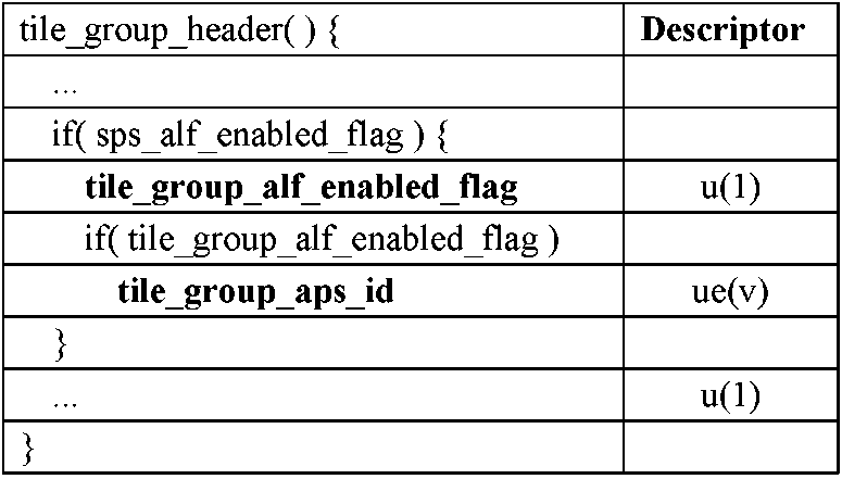
他の実施形態(またはその変形)に関連して説明されるスライス(ヘッダ)はテーブル2のタイルグループヘッダシンタックス(tile group header syntax)によって示されるように、タイルグループ(ヘッダ)によって置き換えられる。したがって、“tile_group_ALF_enabled_flag”は、図2の202および図5の502のシンタックス要素に対応し、ALFがタイルグループに対してアクティブであるかどうかを表す。さらに、ALFデータシンタックス要素は、タイルグループヘッダには提供されない(他の実施形態ではスライスと共に、スライスヘッダに提供されてもよい)。代わりに、ALFデータシンタックス要素はテーブル1に示すように、アダプテーションパラメータセット(Adaptation Parameter Set:APS)と呼ばれる特定のパラメータ設定で提供される。ALFデータは、ALFシンタックス要素を含み、APSにおけるALFデータシンタックス要素の提供は、同一および/または異なる復号化画像における複数のタイルグループ間など、複数のタイルグループ間でALFパラメータを共有することを可能にする。
The slices (headers) described in connection with other embodiments (or variations thereof) are replaced by tile groups (headers), as indicated by the tile group header syntax in Table 2. Thus, "tile_group_ALF_enabled_flag" corresponds to
テーブル1のアダプテーションパラメータセット(APS)シンタックスは、任意のアダプテーションパラメータセットのシグナリングを定義するために使用される。変形例では、APSは、非“ビデオ符号化レイヤ”(VCL)“ネットワーク抽象化レイヤ”(NAL)ユニット(例えば、“APS_NUT”またはAPS NALユニットタイプと呼ばれる)に含まれる。 The Adaptation Parameter Set (APS) syntax in Table 1 is used to define the signaling of any adaptation parameter set. In a variant, the APS is included in a non-“Video Coding Layer” (VCL) “Network Abstraction Layer” (NAL) unit (eg called “APS_NUT” or APS NAL unit type).
APSの各シンタックス要素のセマンティクスは次のとおりである。
アダプテーションパラメータセットセマンティクス
Adaptation_parameter_set_idは、他のシンタックス要素によって参照されるAPSを識別する。adaptation_parameter_set_id の値は、0から63までの範囲内である必要がある。
The semantics of each syntax element of APS are as follows.
Adaptation parameter set semantics
Adaptation_parameter_set_id identifies the APS referenced by other syntax elements. The value of adaptation_parameter_set_id must be in the range 0-63.
テーブル2 のタイルグループヘッダーシンタックスは、各タイルグループヘッダーを定義するために使用される。タイルグループヘッダは、各タイルグループに対して提供される。タイルグループは、タイルのセットを含み、各タイルはCTUのセットを含む。 The tile group header syntax in Table 2 is used to define each tile group header. A tile group header is provided for each tile group. A tile group contains a set of tiles, each tile containing a set of CTUs.
タイルグループヘッダのシンタックス要素のセマンティクスは次のとおりである:
グループヘッダセマンティクス
tile_group_APS_id は、タイルグループが参照するAPS のadaptation_parameter_set_id を特定する。tile_group_aps_idの値は、0から63の範囲内である。adaptation_parameter_set_idがtile_group_APS_idに等しいAPS NALLユニットのTemporalIdは、符号化タイルグループNALユニットのTemporalId以下でなければならない。
The semantics of the tile group header syntax elements are as follows:
Group header semantics
tile_group_APS_id identifies the adaptation_parameter_set_id of the APS referenced by the tile group. The value of tile_group_aps_id is in the range 0-63. The TemporalId of the APS NALL unit whose adaptation_parameter_set_id is equal to the tile_group_APS_id must be less than or equal to the TemporalId of the coded tile group NAL unit.
テーブル3は、CTUレベルで、ALFがアクティブである各成分に使用されるALF(enable)フラグをシグナリングするためのシンタックス要素を提供する。これは、図2の208、209、および210、ならびに図5の508、509、および510で使用されるシンタックス要素に対応する。
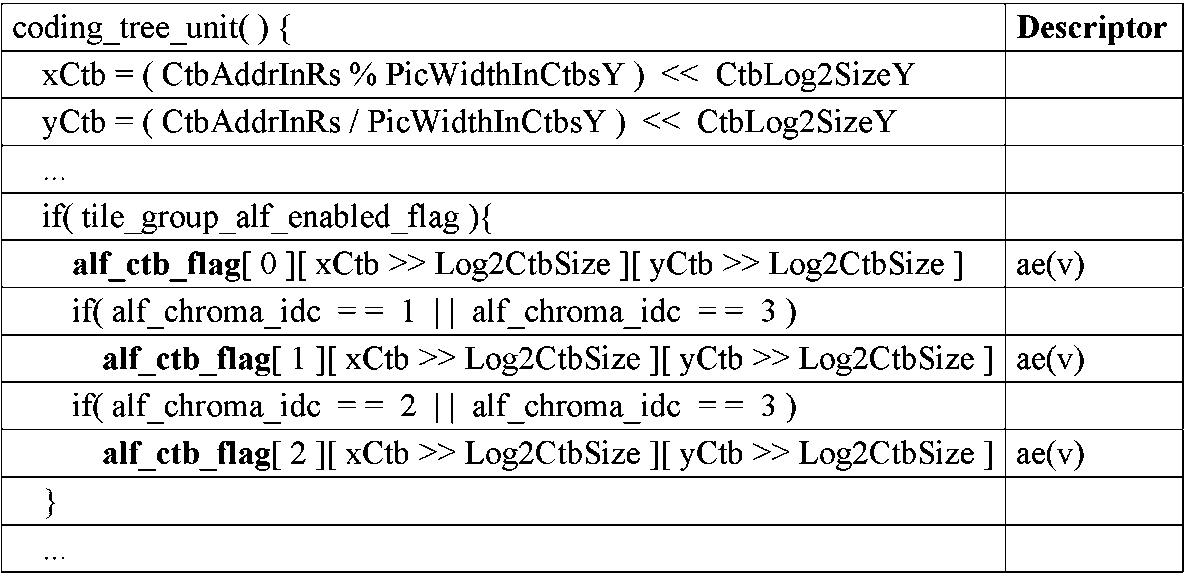
テーブル3のコーディングツリーユニットシンタックスは、(符号化された)符号化ツリーユニットを定義するために使用される。コーディングツリーユニットの各シンタックス要素のセマンティクスは次のとおりである:
コーディングツリーユニットセマンティクス
CTUは、コーディング四分木構造のルートノードである。
alf_ctb_flag[cIdx][xCtb>>Log2CtbSize][yCtb>>Log2CtbSize]=1の場合、アダプティブループフィルタが、ルマロケーション(xCtb、yCtb)のコーディングツリーユニットのcIdx によって示される色成分のコーディングツリーブロックに適用されることを特定する。alf_ctb_flag[cIdx][xCtb>>Log2CtbSize][yCtb>>Log2CtbSize]=0の場合、アダプティブループフィルタが、ルマロケーション(xCtb、yCtb)のコーディングツリーユニットのcIdx によって示される色成分のコーディングツリーブロックに適用されないことを特定する。
The coding tree unit syntax in Table 3 is used to define a (encoded) coding tree unit. The semantics of each syntax element in the coding tree unit are as follows:
Coding tree unit semantics
CTU is the root node of the coding quadtree structure.
If alf_ctb_flag[cIdx][xCtb>>Log2CtbSize][yCtb>>Log2CtbSize]=1 then adaptive loop filter is applied to coding tree block of color component indicated by cIdx in coding tree unit of luma location (xCtb, yCtb) to be specified. If alf_ctb_flag[cIdx][xCtb>>Log2CtbSize][yCtb>>Log2CtbSize]=0 then adaptive loop filter is applied to the coding tree block of the color component indicated by cIdx in the coding tree unit of luma location (xCtb, yCtb) identify what is not
alf_ctb_flag[cIdx][xCtb>>Log2CtbSize][yCtb>>Log2CtbSize]が存在しない場合、0 と推測される。 If alf_ctb_flag[cIdx][xCtb>>Log2CtbSize][yCtb>>Log2CtbSize] does not exist, it is assumed to be 0.
テーブル4は、非線形ALFパラメータ(すなわち、非線形ALFデータシンタックス)をシグナリングするためのシンタックス要素を提供し、これは、VVCドラフトバージョン3のALFデータシンタックス要素に基づいて構築される。これらのシンタックス要素は、図2のシンタックス要素上に構築される図5の非線形ALFシンタックス要素を参照して、本明細書に記載される変形例において使用されるシンタックス要素上に構築される。

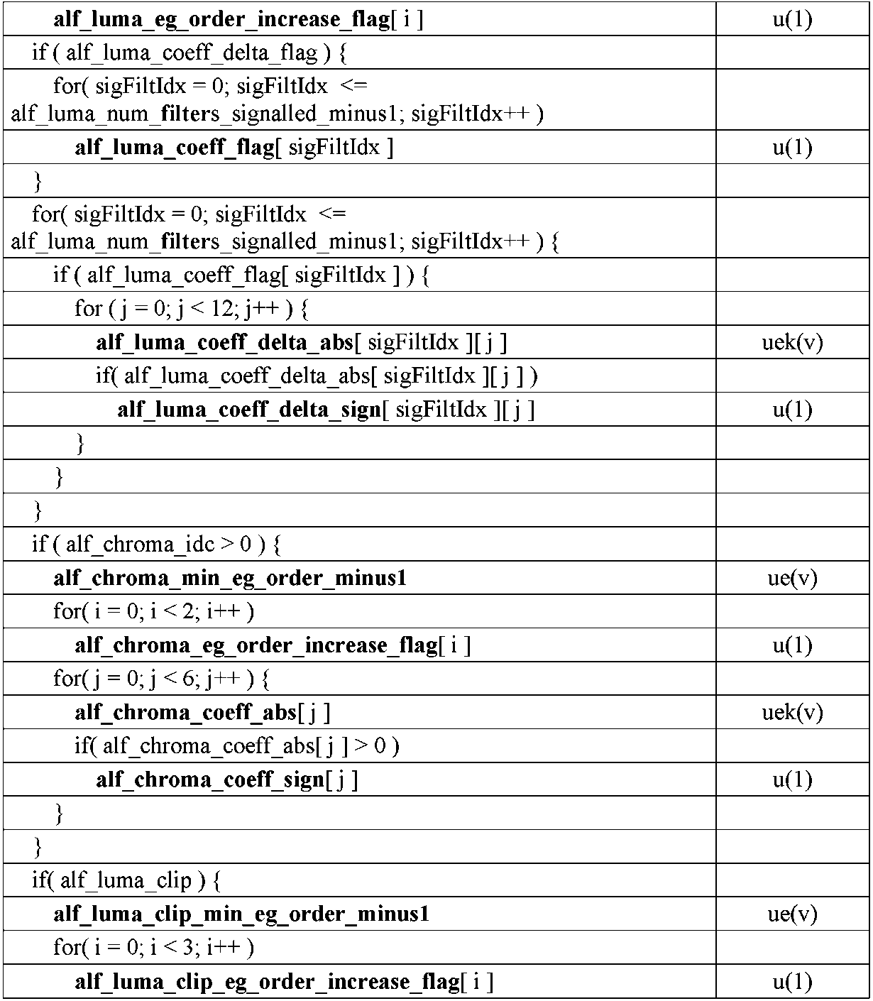

テーブル4の非線形アダプティブループフィルタ(ALF)データシンタックスは、適応パラメータセット(テーブル1に示される)を定義するために使用される。非線形ALFデータシンタックス要素のセマンティックスは以下の通りである:
アダプティブループフィルタデータセマンティクス
alf_chroma_idcが0に等しい場合、アダプティブループフィルタがCbおよびCr色成分に適用されないことを特定する。alf_chroma_idcが1に等しい場合、アダプティブループフィルタがCb色成分に適用されることを特定する。
alf_chroma_idcが2に等しい場合、アダプティブループフィルタがCr色成分に適用されることを示す。alf_chroma_idcが3に等しい場合、アダプティブループフィルタがCbおよびCr色成分に適用されることを示す。
The non-linear adaptive loop filter (ALF) data syntax of Table 4 is used to define the adaptive parameter set (shown in Table 1). The semantics of the non-linear ALF data syntax elements are as follows:
Adaptive loop filter data semantics
If alf_chroma_idc is equal to 0, it specifies that the adaptive loop filter is not applied to the Cb and Cr color components. If alf_chroma_idc is equal to 1, it specifies that the adaptive loop filter is applied to the Cb color component.
If alf_chroma_idc is equal to 2, it indicates that the adaptive loop filter is applied to the Cr color component. If alf_chroma_idc is equal to 3, it indicates that the adaptive loop filter is applied to the Cb and Cr color components.
切り捨て後の単項2値tu(v)の最大値maxValは、3に等しく設定される。 The maximum value maxVal of the unary binary tu(v) after truncation is set equal to three.
異なるアダプティブループフィルタ数を特定する変数NumAlfFilterは、25に等しく設定される。 The variable NumAlfFilter, which specifies the number of different adaptive loop filters, is set equal to twenty-five.
alf_luma_num_filters_signalled_minus1 +1は、ルマ係数をシグナリングできるアダプティブループフィルタクラスの数を特定する。alf_luma_num_filters_signalled_minus1 の値は、0 からNumAlfFilters-1 までの範囲内である必要がある。
切り捨て後のバイナリ二値化tb(v) の最大値maxValは、NumAlfFilters-1 に等しく設定される。 The maximum value maxVal of the binary binarization tb(v) after truncation is set equal to NumAlfFilters-1.
alf_luma_coeff_delta_idx[filtIdx]は、0からNumAlfFilters-1までの範囲のfiltIdxで示されるフィルタクラスのシグナリングされたアダプティブループフィルタルマ係数デルタのインデックスを指定する。alf_luma_coeff_delta_idx[filtIdx]が存在しない場合、0 に等しいと推測される。 alf_luma_coeff_delta_idx[filtIdx] specifies the index of the signaled adaptive loop filter luma coefficient delta for the filter class indicated by filtIdx, ranging from 0 to NumAlfFilters−1. If alf_luma_coeff_delta_idx[filtIdx] does not exist, it is assumed to be equal to 0.
切り捨て後のバイナリニ値化tb(v) の最大値maxVal は、alf_luma_num_filters_signalled_minus1 に設定される。 The maximum value maxVal of binary binarization tb(v) after truncation is set to alf_luma_num_filters_signalled_minus1.
alf_luma_coeff_delta_flag が1 に等しい場合、alf_luma_coeff_delta_prediction_flag がシグナリングされないことを示す。alf_luma_coeff_delta_flag が0 の場合、alf_luma_coeff_delta_prediction_flag がシグナリングされる可能性があることを示す。 If alf_luma_coeff_delta_flag is equal to 1, it indicates that alf_luma_coeff_delta_prediction_flag is not signaled. If alf_luma_coeff_delta_flag is 0, it indicates that alf_luma_coeff_delta_prediction_flag may be signaled.
alf_luma_coeff_delta_prediction_flag が1 に等しい場合、シグナリングされたルマフィルタ係数デルタが、以前のルミナンス係数のデルタから予測されることを特定する。alf_luma_coeff_delta_prediction_flag が0 に等しい場合、シグナリングされたルマフィルタ係数デルタが、以前のルマ係数のデルタから予測されないことを指定する。存在しない場合、alf_luma_coeff_delta_prediction_flag は0 に等しいと推測される。 If alf_luma_coeff_delta_prediction_flag is equal to 1, it specifies that the signaled luma filter coefficient delta is predicted from the previous luminance coefficient delta. If alf_luma_coeff_delta_prediction_flag is equal to 0, it specifies that the signaled luma filter coefficient deltas are not predicted from the deltas of previous luma coefficients. If not present, alf_luma_coeff_delta_prediction_flag is assumed to be equal to 0.
alf_luma_min_eg_order_minus1 + 1 は、ルマフィルタ係数のシグナリングのためのexp-Golomb コードの最小の次数を特定する。alf_luma_min_eg_order_minus1 の値は、0 以上6 以下の範囲とする。
alf_luma_eg_order_increase_flag[i]が1に等しい場合、ルマフィルタ係数シグナリングのexp-Golomb符号の最小次数が1だけインクリメントされることを特定する。alf_luma_eg_order_increase_flag[i]が0に等しい場合、ルマフィルタ係数シグナリングのexp-Golomb符号の最小次数が1だけインクリメントされないことを特定する。 If alf_luma_eg_order_increase_flag[i] is equal to 1, it specifies that the minimum degree of the exp-Golomb code of the luma filter coefficient signaling is incremented by one. If alf_luma_eg_order_increase_flag[i] is equal to 0, it specifies that the minimum degree of the exp-Golomb code of the luma filter coefficient signaling is not incremented by one.
alf_luma_coeff_delta_abs[sigFiltIdx][j]の値をデコードするために使用されるexp-Golomb符号の次数expGoOrderY[i]は、次のように導出される:
expGoOrder[i]=alf_luma_min_eg_oreder_minus1+1+ald_luma_eg_order_increase_flag[i]
The order expGoOrderY[i] of the exp-Golomb code used to decode the values of alf_luma_coeff_delta_abs[sigFiltIdx][j] is derived as follows:
expGoOrder[i]=alf_luma_min_eg_order_minus1+1+ald_luma_eg_order_increase_flag[i]
alf_luma_coeff_flag[sigFiltIdx]が1に等しい場合、sigFiltIdxで表されるルマフィルタの係数がシグナリングされることを特定する。alf_luma_coeff_flag[sigFiltIdx]が0に等しい場合、sigFiltIdxで表されるルマフィルタの全ての係数が0にセットされることを特定する。 If alf_luma_coeff_flag[sigFiltIdx] is equal to 1, it specifies that the coefficients of the luma filter represented by sigFiltIdx are signaled. If alf_luma_coeff_flag[sigFiltIdx] is equal to 0, specify that all coefficients of the luma filter represented by sigFiltIdx are set to 0.
alf_luma_coeff_delta_abs[sigFiltIdx][j]は、sigFiltIdxで表されるシグナリングされたルマフィルタのj番目の係数デルタの絶対値を特定する。alf_luma_coeff_delta_abs[sigFiltIdx][j]が存在しない場合、0 に等しいと推測される。 alf_luma_coeff_delta_abs[sigFiltIdx][j] specifies the absolute value of the jth coefficient delta of the signaled luma filter represented by sigFiltIdx. If alf_luma_coeff_delta_abs[sigFiltIdx][j] does not exist, it is assumed to be equal to 0.
exp-Golombのバイナリuek(v)の次数kは、次のように導出される:
golombOrderIdxY[]={0、0、1、0、0、1、2、1、0、0、1、2 }
k=expGoOrderY[golombOrderIdxY[j]]
The order k of exp-Golomb's binary uek(v) is derived as follows:
golombOrderIdxY[] = {0, 0, 1, 0, 0, 1, 2, 1, 0, 0, 1, 2}
k=expGoOrderY[golombOrderId xY[j]]
alf_luma_coeff_delta_sign[sigFiltIdx][j]は、sigFiltIdx が示すフィルタのj 番目のルマ係数の符号を次のように指定する:- もしalf_Luma_coeff_delta_sign[sigFiltIdx][j]が0に等しい場合、対応するルマフィルタ係数は正の値を持つ。
- それ以外(alf_Luma_coeff_delta_sign[sigFiltIdx][j]が1に等しい場合)、対応するルマフィルタ係数は負の値を持つ。
ALF_LUMA_COEFFF_DELTA_SIGN [SigFiltidX] [J] specifies the sign of the J's J -coefficient of filter as shown by SigFilTidX as follows: --Alf_luma_coeff_sign [Sig If FILTIDX] [J] is equal to zero, the corresponding Lumafilta coefficient is positive. has a value of
- Otherwise (if alf_Luma_coeff_delta_sign[sigFiltIdx][j] is equal to 1), the corresponding luma filter coefficient has a negative value.
alf_luma_coeff_delta_sign[sigFiltIdx][j]が存在しない場合、0に等しいと推測される。 If alf_luma_coeff_delta_sign[sigFiltIdx][j] does not exist, it is assumed to be equal to 0.
sigFiltIdxが0~alf_luma_num_filter_signaled_minus1、jが0~11であるときの、変数filterCoefficients[sigFiltIdx][j]は次のように初期化される。
filterCoefficients[sigFiltIdx][j]=alf_luma_coeff_delta_abs[sigFiltIdx][j]*(1-2*alf_Luma_coeff_delta_sign[sigFiltIdx][j])
When sigFiltIdx is 0 to alf_luma_num_filter_signaled_minus1 and j is 0 to 11, the variable filterCoefficients[sigFiltIdx][j] is initialized as follows.
filterCoefficients[sigFiltIdx][j]=alf_luma_coeff_delta_abs[sigFiltIdx][j]*(1−2*alf_luma_coeff_delta_sign[sigFiltIdx][j])
alf_luma_coeff_delta_prediction_flagが1に等しい場合、sigFiltIdxgが1~alf_luma_num_filters_signalled_minus1で、jが0~11である場合のfilterCoefficients[sigFiltIdx]「j」は、次のように変形される。
filterCoefficents[sigFiltIdx][j]+=filterCoefficients[sigFiltIdx-1][j]
If alf_luma_coeff_delta_prediction_flag is equal to 1, then filterCoefficients[sigFiltIdx] 'j' where sigFiltIdxg is 1 to alf_luma_num_filters_signaled_minus1 and j is 0 to 11 is as follows: Transformed.
filterCoefficients[sigFiltIdx][j]+=filterCoefficients[sigFiltIdx−1][j]
filtIdxが0~NumAlfFilter-1で、jが0~11であるときの要素AlfCoefL「filtIdx」[j]でのルマフィルタ係数alfCoeffLは、次のように導出される。
AlfCoeffL[filtIdx][j]=filterCoefficients[alf_luma_coeff_delta_idx[filtIdx][j]
The luma filter coefficient alfCoeffL at element AlfCoefL 'filtIdx'[j] when filtIdx is 0 to NumAlfFilter-1 and j is 0 to 11 is derived as follows.
AlfCoeffL[filtIdx][j] = filterCoefficients[alf_luma_coeff_delta_idx[filtIdx][j]
filtIdxが0~NumAlfFilters-1での、最後のフィルタ係数AlfCoeffL[filtIdx][12]は、次のように導出される。
AlfCoeffL[filtIdx][12]=128
The final filter coefficient AlfCoeffL[filtIdx][12], with filtIdx from 0 to NumAlfFilters−1, is derived as follows.
AlfCoeffL[filtIdx][12]=128
filtIdxが0~NumAlfFilter-1、jが0~11におけるAlfCoeffL[filtIdx][j]の値は-2^7 ~ 2^7 -1 の範囲であり、AlfCoeffL[filtIdx][12]の値は0~ 2^8 -1 の範囲内であることが、ビットストリームの適合の要件である。 The value of AlfCoeffL[filtIdx][j] where filtIdx is from 0 to NumAlfFilter-1 and j is from 0 to 11 is in the range of -2^7 to 2^7-1, and the value of AlfCoeffL[filtIdx][12] is 0 ∼ 2^8 -1 is a requirement for bitstream conformance.
alf_chroma_min_eg_order_minus1 + 1 は、クロマフィルタ係数シグナリングのexp-Golomb符号の最小次数を特定する。alf_chroma_min_eg_order_minus1の値は、0~6以の範囲内とする。
alf_Chroma_eg_order_increase_flag[i]が1に等しい場合、クロマフィルタ係数シグナリングのためのexp-Golomb符号の最小次数を1だけインクリメントすることを特定する。alf_Chroma_eg_order_increase_flag[i]が0に等しい場合、クロマフィルタ係数シグナリングのためのexp-Golomb符号の最小次数を1だけインクリメントしないことを特定する。 If alf_Chroma_eg_order_increase_flag[i] is equal to 1, it specifies to increment by 1 the minimum degree of the exp-Golomb code for chroma filter coefficient signaling. If alf_Chroma_eg_order_increase_flag[i] is equal to 0, it specifies not to increment the minimum degree of the exp-Golomb code for chroma filter coefficient signaling by one.
alf_chroma_coeff_abs[j]の値をデコードするために使用されるexp-Golomb符号の次数expGoOrderC[i]は、次のように導出される:
expGoOrderC[i]=alf_chroma_min_eg_order_minus1+1+alf_chroma_eg_order_increase_flag[i]
The order expGoOrderC[i] of the exp-Golomb code used to decode the values of alf_chroma_coeff_abs[j] is derived as follows:
expGoOrderC[i]=alf_chroma_min_eg_order_minus1+1+alf_chroma_eg_order_increase_flag[i]
alf_chroma_coeff_abs[j]は、j番目のクロマフィルタ係数の絶対値を特定する。alf_chroma_coeff_abs[j]が存在しない場合、0に等しいと推測される。 alf_chroma_coeff_abs[j] specifies the absolute value of the jth chroma filter coefficient. If alf_chroma_coeff_abs[j] does not exist, it is assumed to be equal to 0.
exp-Golombバイナリuek()の次数は、次のように導出される。
golombOrderIdxC[]={0、0、1、0、0、1}
k=expGoOrderC[golombOrderIdxC[j]]
The degree of exp-Golomb binary uek() is derived as follows.
golombOrderId x C[] = {0, 0, 1, 0, 0, 1}
k=expGoOrderC[golombOrderIdxC[j]]
alf_chroma_coeff_sign[j]は、j番目のクロマフィルタ係数の符号を特定するもので、次の通りである。
- もし、alf_chroma_coeff_sign[j]が0に等しい場合は、対応するクロマフィルタ係数は正の値を持つ
- これ以外(alf_chroma_coeff_sign[j]が1に等しい)の場合は、対応するクロマフィルタ係数は負の正を持つ。
alf_chroma_coeff_sign[j] specifies the sign of the j-th chroma filter coefficient as follows.
- if alf_chroma_coeff_sign[j] equals 0, then the corresponding chroma filter coefficient has a positive value - otherwise (alf_chroma_coeff_sign[j] equals 1), the corresponding chroma filter coefficient has a negative value have a positive
alf_chroma_coeff_sign[j]が存在しない場合は、0に等しいと推測される。 If alf_chroma_coeff_sign[j] does not exist, it is assumed to be equal to 0.
要素cC[j]を持ち、jが0~5の場合のクロマフィルタ係数alfCoeffCは、次のように導出される。
AlfCoeffC[j]=alf_chroma_coeff_abs[j]*(1-2*alf_chroma_coeff_sign[j])
A chroma filter coefficient alfCoeffC having an element cC[j], where j is 0 to 5, is derived as follows.
AlfCoeffC[j]=alf_chroma_coeff_abs[j]*(1-2*alf_chroma_coeff_sign[j])
j=6の場合の最後のフィルタ係数は、次のように導出される。
AlfCoeffC[6]=128
The final filter coefficients for j=6 are derived as follows.
AlfCoeffC[6] = 128
jが0~5の場合のAlfCoeffC[j]の値は、-2^7~2^7-1の範囲内にあり、AlfCoeffC[6]は0~2^8-1の範囲内にあることが、ビットストリーム適合の要件である。 The value of AlfCoeffC[j], where j is 0 to 5, shall be in the range of -2^7 to 2^7-1, and AlfCoeffC[6] shall be in the range of 0 to 2^8-1. is a requirement for bitstream conformance.
alf_luma_clipが0に等しい場合は線形アダプティブループフィルタがルマ成分に適用されることを特定し、alf_luma_clipが1に等しい場合は、非線形アダプティブループフィルタがルマ成分に適用されること特定する。 alf_luma_clip equal to 0 specifies that a linear adaptive loop filter is applied to the luma component, and alf_luma_clip equal to 1 specifies that a non-linear adaptive loop filter is applied to the luma component.
alf_chroma_clipが0に等しい場合は線形アダプティブループフィルタがクロマ成分に適用されることを特定し、alf_chroma_clipが1に等しい場合は、非線形アダプティブループフィルタがクロマ成分に適用されること特定する。alf_chroma_clipが存在しない場合は0であると推測される。 alf_chroma_clip equal to 0 specifies that a linear adaptive loop filter is applied to the chroma component, and alf_chroma_clip equal to 1 specifies that a non-linear adaptive loop filter is applied to the chroma component. It is assumed to be 0 if alf_chroma_clip does not exist.
alf_luma_clip_default_tableが1に等しい場合、デフォルトのalf_luma_clipping_valu[]テーブルが、クリッピングインデックスをクリッピング値に変換するために使用される。alf_luma_clip_default_tableが0に等しい場合は。alf_luma_clipping_value[]テーブルがalf_data()内に存在することを示す。 If alf_luma_clip_default_table is equal to 1, the default alf_luma_clipping_value[ ] table is used to convert clipping indices to clipping values. if alf_luma_clip_default_table is equal to 0; Indicates that the alf_luma_clipping_value[] table exists in alf_data().
alf_luma_num_clipping_values_minus1 + 1 は、alf_luma_clipping_value[]テーブルのサイズを示す。存在しない場合、bitDepthY に等しいと推測される。
alf_luma_clipping_value[clipIdx]は、alf_luma_clip_idx[][]テーブルにてクリッピングインデックスclipIdxがシグナリングされたときに使用するクリッピング値を特定する。存在しない場合、alf_luma_clipping_value[]={1 << bitDepthY、1 <<(bitDepthY-1)、...、8、4、2 }であるとと推測される。 alf_luma_clipping_value[clipIdx] specifies the clipping value to use when the clipping index clipIdx is signaled in the alf_luma_clip_idx[][] table. If not, alf_luma_clipping_value[]={1 << bitDepthY, 1 <<(bitDepthY-1), . . . , 8, 4, 2}.
便宜上、alf_luma_clipping_value[alf_luma_num_clipping_values_minus1+1]は、1 << bitDepthYに等しいと推論される。 For convenience, alf_luma_clipping_value[alf_luma_num_clipping_values_minus1+1] is inferred to be equal to 1 << bitDepthY.
alf_chroma_clip_default_table が1に等しい場合は、クリッピングインデックスをクリッピング値に変換するためにデフォルトのalf_chroma_clipping_value[]テーブルが使用されること特定し、alf_chroma_clip_default_table が0に等しい場合は、alf_data()内にalf_chroma_clipping_value[]テーブルが存在することを示す。 If alf_chroma_clip_default_table is equal to 1, specify that the default alf_chroma_clipping_value[] table is used to convert clipping indices to clipping values; The a_clipping_value[] table is Indicates that it exists.
alf_chroma_num_clipping_values_minus1 + 1 は、alf_chroma_clipping_value[]テーブルのサイズを示す。存在しない場合、それはbitDepthCに等しいと推測される。
alf_chroma_clipping_value[clipIdx]は、alf_chroma_clip_idx[][]テーブル内に、インデックスクリップclipIdx がシグナリングされるときに使用されるクリッピング値を特定する。存在しない場合、alf_chroma_clipping_value[]={1 << bitDepthC、1 <<(bitDepthC-1)、...、8、4、2 } と推測される。 alf_chroma_clipping_value[clipIdx] specifies the clipping value used when the index clip clipIdx is signaled in the alf_chroma_clip_idx[][] table. If not, alf_chroma_clipping_value[]={1 << bitDepthC, 1 <<(bitDepthC-1), . . . , 8, 4, 2}.
便宜上、alf_chroma_clipping_value[alf_chroma_num_clipping_values_minus1 + 1 ] は、1<<bitDepthCと等しいと推測される。 For convenience, alf_chroma_clipping_value[alf_chroma_num_clipping_values_minus1+1] is assumed to be equal to 1<<bitDepthC.
alf_luma_filter_clip[sigFiltIdx]が0 に等しい場合、sigFiltIdx で示されるルナフィルタで線形アダプティブループフィルタが適用されることを特定する。alf_luma_filter_clip[sigFiltIdx]が1に等しい場合、sigFiltIdx が示すルナフィルタで非線形アダプティブループフィルタが適用されることを特定する。 If alf_luma_filter_clip[sigFiltIdx] is equal to 0, it specifies that a linear adaptive loop filter is applied with the lunar filter indicated by sigFiltIdx. If alf_luma_filter_clip[sigFiltIdx] is equal to 1, it specifies that a non-linear adaptive loop filter is applied with the lunar filter indicated by sigFiltIdx.
alf_luma_clip_min_eg_order_minus1 + 1 は、ルマフィルタ係数シグナリングのexp-Golomb符号の最小次数を特定する。alf_luma_clip_min_eg_order_minus1 の値は、0~6の範囲内とする。
alf_luma_clip_eg_order_increase_flag[i]が1に等しい場合、ルマフィルタ係数シグナリングのexp-Golomb符号の最小次数が1だけインクリメントされることを特定する。alf_luma_clip_eg_order_increase_flag[i]が0 に等しい場合、ルマフィルタ係数シグナリングのexp-Golomb符号の最小次数が1だけインクリメントされないことを特定する。 If alf_luma_clip_eg_order_increase_flag[i] is equal to 1, it specifies that the minimum order of the exp-Golomb code in the luma filter coefficient signaling is incremented by one. If alf_luma_clip_eg_order_increase_flag[i] is equal to 0, it specifies that the minimum degree of the exp-Golomb code of the luma filter coefficient signaling is not incremented by one.
alf_luma_clip_idx[sigFiltIdx][j]の値をデコードするために使用されるexp-Golomb符号の次数expGoOrderYClip[i]は、次のように導出される:
expGoOrderYClip[i]=alf_luma_clip_min_eg_order_minus1+1+alf_luma_clip_eg_order_increase_flag[i]
The order expGoOrderYClip[i] of the exp-Golomb code used to decode the values of alf_luma_clip_idx[sigFiltIdx][j] is derived as follows:
expGoOrderYClip[i]=alf_luma_clip_min_eg_order_minus1+1+alf_luma_clip_eg_order_increase_flag[i]
alf_luma_clip_idx[sigFiltIdx][j]は、sigFiltIdxで表されるシグナリングされたルマフィルタのj番目の係数で乗算する前に使用されるクリッピングのクリッピングインデックスを特定する。alf_luma_clip_idx[sigFiltIdx][j]が存在しない場合、alf_luma_num_clipping_values_minus1+1(クリッピング無し)に等しいと推測される。 alf_luma_clip_idx[sigFiltIdx][j] specifies the clipping index of the clipping used before multiplication by the jth coefficient of the signaled luma filter represented by sigFiltIdx. If alf_luma_clip_idx[sigFiltIdx][j] does not exist, it is assumed to be equal to alf_luma_num_clipping_values_minus1+1 (no clipping).
exp-Golombバイナリuek(v)の次数kは、次のように導出される:
golombOrderIdxYClip[]={0、0、1、0、0、1、2、1、0、0、1、2 }
k = expGoOrderYClip[golombOrderIdxYClip[j]]
The order k of the exp-Golomb binary uek(v) is derived as follows:
golombOrderIdxYClip[]={0, 0, 1, 0, 0, 1, 2, 1, 0, 0, 1, 2}
k = expGoOrderYClip[golombOrderId x YClip[j]]
sigFiltIdxが0~alf_luma_num_filters_signalled_minus1で、jが0~11である場合の変数filterClips[sigFiltIdx][j]は、次のように初期化される。
filterClips[sigFiltIdx][j]=ald_luma_clipping_value[alf_luma_clip_idx[sigFiltIdx][j]]
The variable filterClips[sigFiltIdx][j] where sigFiltIdx is 0 to alf_luma_num_filters_signaled_minus1 and j is 0 to 11 is initialized as follows.
filterClips[sigFiltIdx][j]=ald_luma_clipping_value[alf_luma_clip_idx[sigFiltIdx][j]]
要素AlfClipC[filtIdx][j]を持ち、filtIdxが0~NumAlfFilters-1、Jが0~11である場合の、ルマフィルタクリッピング値AlfClipLは、次のように初期化される。
AlfClipL[filtIdx][j]=filterClips[alf_luma_coeff_delta_idx[filtIdx]][j]
The luma filter clipping value AlfClipL, with element AlfClipC[filtIdx][j], where filtIdx is 0 to NumAlfFilters−1 and J is 0 to 11, is initialized as follows.
AlfClipL[filtIdx][j] = filterClips[alf_luma_coeff_delta_idx[filtIdx]][j]
alf_chroma_clip_min_eg_order_minus1+1は、クロマフィルタ係数シグナリングのexp-Golomb符号の最小次数を特定する。alf_chroma_clip_min_eg_order_minus1の値は、0~7の範囲内とする。
alf_chroma_clip_eg_order_increase_flag[i]が1に等しい場合、クロマフィルタ係数シグナリングのexp-Golomb符号の最小次数は1だけ増加することを特定する。alf_chroma_clip_eg_order_increase_flag[i]が0に等しい場合、クロマフィルタ係数シグナリングのexp-Golomb符号の最小次数は1だけ増加しないことを特定する。 If alf_chroma_clip_eg_order_increase_flag[i] is equal to 1, it specifies that the minimum order of the exp-Golomb code in the chroma filter coefficient signaling is increased by one. If alf_chroma_clip_eg_order_increase_flag[i] is equal to 0, it specifies that the minimum order of the exp-Golomb code in the chroma filter coefficient signaling is not increased by one.
alf_chroma_coeff_abs[j]の値をデコードする際に使用するexp-Golomb符号の次数expGoOrderC[i]は、次のように導出される。
expGoOrderC[i]=alf_chroma_clip_eg_order_minus1+1+alf_chroma_clip_eg_order_increase_flag[i]
The order expGoOrderC[i] of the exp-Golomb code used in decoding the value of alf_chroma_coeff_abs[j] is derived as follows.
expGoOrderC[i]=alf_chroma_clip_eg_order_minus1+1+alf_chroma_clip_eg_order_increase_flag[i]
alf_chroma_clip_inx[j]は、クロマフィルタのj番目の係数で乗算する前に使用されるクリッピングのクリッピングインデックスを特定する。alf_chroma_clip_inx[j]が存在しない場合は、alf_chroma_num_clip_values_minus1+1(クリッピング無し)に等しいと推測される。 alf_chroma_clip_inx[j] specifies the clipping index of the clipping used before multiplying by the jth coefficient of the chroma filter. If alf_chroma_clip_inx[j] does not exist, it is assumed to be equal to alf_chroma_num_clip_values_minus1+1 (no clipping).
exp-Golombバイナリuek(v)の次数kは次のように導出される。
golombOrderIdxC[]={0,0,1,0.0,1}
k=expGoOrderC[golombOrderIdxC[j]]
The order k of exp-Golomb binary uek(v) is derived as follows.
golombOrderId x C[] = {0,0,1,0.0,1}
k=expGoOrderC[golombOrderIdxC[j]]
jが0~5における要素AltClipC[j]を持つ、クロマフィルタクリッピング値AlfClipCは、次のように導出される。
AlfClipC[j]=alf_chroma_clipping_value[alf_chroma_clip_idx[j]]
The chroma filter clipping value AlfClipC, with elements AltClipC[j] where j is 0 to 5, is derived as follows.
AlfClipC[j]=alf_chroma_clipping_value[alf_chroma_clip_idx[j]]
変形例によれば、alf_luma_num_clipping_values_minus1 は、alf_luma_num_clipping_values_minus2 に置き換えられ、クリッピング値はindex=1 からalf_luma_num_clipping_values_minus2+1 に提供され、alf_luma_clipping_value[]の最初の値alf_luma_clipping_value[ 0]=1<<bitDepthY として推測される。alf_chroma_num_clipping_values_minus1 は、alf_chroma_num_clipping_values_minus2 に置き換えられ、クリッピング値はindex=1 からalf_chroma_num_clipping_values_minus2+1 に提供され、alf_chroma_clipping_value[]の最初の値は、alf_chroma_clipping_value[ 0]= 1<<bitDepthC として推測される。 According to a variant, alf_luma_num_clipping_values_minus1 is replaced by alf_luma_num_clipping_values_minus2, the clipping values are provided from index=1 to alf_luma_num_clipping_values_minus2+1, alf_luma_ The initial value of clipping_value[] is inferred as alf_luma_clipping_value[0]=1<<bitDepthY. alf_chroma_num_clipping_values_minus1 is replaced by alf_chroma_num_clipping_values_minus2, the clipping values are provided from index=1 to alf_chroma_num_clipping_values_minus2+1, and alf_chroma_clipping The initial value of _value[] is inferred as alf_chroma_clipping_value[0]=1<<bitDepthC.
変形例によれば、アダプティブループフィルタリング処理は、上記のシンタックス要素を使用する。このような変形例は、以下のVVCドラフト仕様書の表記規則を用いて、以下のよう説明される。
アダプティブループフィルタ処理
一般
このプロセスの入力は、アダプティブループフィルタrecPictureL、recPictureCb、およびrecPictureCrの前の、再構成画像サンプルアレイである。
このプロセスの出力は、アダプティブループフィルタalfPictureL、alfPictureCb、およびalfPictureCrの後の、修正された再構成されたピクチャサンプルアレイである。
According to a variant, the adaptive loop filtering process uses the above syntax elements. Such variations are described below using the conventions of the VVC draft specification below.
Adaptive loop filtering
General
The input of this process is the reconstructed image sample array before the adaptive loop filters recPictureL, recPictureCb, and recPictureCr.
The output of this process is a modified reconstructed picture sample array after adaptive loop filters alfPictureL, alfPictureCb, and alfPictureCr.
アダプティブループフィルタalfPictureL,alfPictureCb,alfPictureCrの後の修正後の再構成されたピクチャアンプルアレイにおけるサンプル値は、最初は、アダプティブループフィルタrecPictureL、recPictureCb、recPictureCrそれぞれを適用する以前の再構成されたピクチャサンプル値に等しくなるようにセットされる。 The sample values in the modified reconstructed picture ample array after the adaptive loop filters alfPictureL, alfPictureCb, alfPictureCr are initially the reconstructed picture sample values before applying the adaptive loop filters recPictureL, recPictureCb, recPictureCr, respectively. is set to be equal to
tile_group_alf_enabled_flag が1に等しいとき、rx=0~PicWidthCtbs-1、ry」=0~PicHeighyInCtBs-1とする、ルマコーディングツリーブロックロケーション(rx、ry)を持つすべてのコーディングツリーユニットについて、次のように適用がなされる。 For all coding tree units with luma coding tree block location (rx, ry), where rx = 0 to PicWidthCtbs-1, ry' = 0 to PicHeighyInCtBs-1, when tile_group_alf_enabled_flag is equal to 1, apply as follows is done.
alf_ctb_flag[0][rx][ry]が1に等しい場合、“ルマサンプルのコーディングツリーブロックフィルタリング処理”の句で特定されているルマサンプルのコーディングツリーブロックフィルタリング処理が、recPictureL、alfPictureL、及び、ルマコーディングツリーブロックロケーション(xCtb、yCtb) が入力として(rx << CtbLog2SizeY、ry << CtLog2SizeY) として読み出され、その出力は修正されたフィルタリング後のピクチャalfPictureLとなる。 If alf_ctb_flag[0][rx][ry] is equal to 1, then the coding tree block filtering process for luma samples specified in the section "coding tree block filtering process for luma samples" is applied to recPictureL, alfPictureL, and luma The coding tree block location (xCtb, yCtb) is read as input as (rx << CtbLog2SizeY, ry << CtLog2SizeY) and the output is the modified filtered picture alfPictureL.
alf_ctb_flag[1][rx][ry]が1に等しい場合、“クロマサンプルのコーディングツリーブロックフィルタリング処理”の句で特定されているクロマサンプルのコーディングツリーブロックフィルタリング処理が、recPictureCbに等しいRecPictureセット、alfPictureCbに等しいalfPictureセット、及び、クロマコーディングツリーブロックロケーション(xCtbc、yCtbC) が入力として(rx <<(CtbLog2SizeY-1)、ry << (CtLog2SizeY-1))として読み出され、その出力は修正されたフィルタリング後のピクチャalfPictureCbとなる。 If alf_ctb_flag[1][rx][ry] is equal to 1, then the chroma sample coding tree block filtering process specified in the clause "chroma sample coding tree block filtering process" is equal to recPictureCb RecPicture set, alfPictureCb and the chroma coding tree block location (xCtbc, yCtbC) is read as input (rx << (CtbLog2SizeY-1), ry << (CtLog2SizeY-1)) and its output is modified The picture after filtering is alfPictureCb.
alf_ctb_flag[2][rx][ry]が1に等しい場合、“クロマサンプルのコーディングツリーブロックフィルタリング処理”の句で特定されているクロマサンプルのコーディングツリーブロックフィルタリング処理が、
recPictureCrに等しいRecPictureセット、alfPictureCrに等しいalfPictureセット、及び、クロマコーディングツリーブロックロケーション(xCtbc、yCtbC) が入力として(rx << (CtbLog2SizeY-1)、ry <<(CtLog2SizeYー1))として読み出され、その出力は修正されたフィルタリング後のピクチャalfPictureCrとなる。
If alf_ctb_flag[2][rx][ry] is equal to 1, then the chroma sample coding tree block filtering operation specified in the section "Chroma Sample Coding Tree Block Filtering Operation" is:
RecPicture set equal to recPictureCr, alfPicture set equal to alfPictureCr, and chroma coding tree block location (xCtbc, yCtbC) are read as inputs (rx << (CtbLog2SizeY-1), ry << (CtLog2SizeY-1)) , whose output is the modified filtered picture alfPictureCr.
ルマサンプルのためのコーディングツリーブロックフィルタリング処理
このプロセスの入力は、アダプティブループフィルタリングプロセスの前の再構成されたルマピクチャサンプルアレイrecPictureL、フィルタリングされた再構成されたルマピクチャサンプルアレイalfPictureL、現在の画像の左上サンプルに対する現在のルマ符号化ツリーブロックの左上サンプルを特定するルマロケーション(xCtb、yCtb)である。
このプロセスの出力は、修正されフィルタリング後の再構成ルマピクチャサンプルアレイalfPictureLである。
Coding Tree Block Filtering Process for Luma Samples The inputs of this process are the reconstructed luma picture sample array recPictureL before the adaptive loop filtering process, the filtered reconstructed luma picture sample array alfPictureL, the The luma location (xCtb, yCtb) that identifies the upper left sample of the current luma coding treeblock for the upper left sample.
The output of this process is the modified and filtered reconstructed luma picture sample array alfPictureL.
“ALF転置のための導出プロセスおよび輝度サンプルのためのフィルタインデックス”のフィルタインデックス節の導出プロセスは、ロケーション(xCtb、yCtb)および再構成されたルマピクチャサンプルアレイrecPictureLを入力とし呼び出され、x、y=0~CtbSizeY-1における、filtIdx[x][y]およびtransposeIdx[x][y]は出力として呼びだされる。 The filter index derivation process of the “Derivation Process for ALF Transpose and Filter Indexes for Luminance Samples” is called with the location (xCtb, yCtb) and the reconstructed luma picture sample array recPictureL as input, x, filtIdx[x][y] and transposeIdx[x][y] for y=0 to CtbSizeY-1 are called as outputs.
フィルタリングされた再構成ルマサンプルalfPictureL[x][y]の導出のために、現在のルマコーディングツリーブロックrecPictureL[x][y]内の各再構成ルマサンプルは、x、y = 0~CtbSize-1にて、次のようにフィルタリングされる。
filtIdx[x][y]によって指定されるフィルタに対応するルマフィルタ係数f[j]のアレイおよびルマフィルタクリッピングc[j]のアレイは、j = 0~12で以下のように導出される。
f[j]=AlfCoeffL[FiltIdx[x][y]][j]
c[j]=AlfClipL[FiltIdx[x][y]][j]
For the derivation of the filtered reconstructed luma samples alfPictureL[x][y], each reconstructed luma sample in the current luma coding tree block recPictureL[x][y] is represented by x,y=0 to CtbSize− 1 is filtered as follows.
The array of luma filter coefficients f[j] and the array of luma filter clippings c[j] corresponding to the filter specified by filtIdx[x][y] are derived for j=0-12 as follows.
f[j]=AlfCoeffL[Filtldx[x][y]][j]
c[j]=AlfClipL[FiltIdx[x][y]][j]
ルマフィルタ係数filterCoeffおよびフィルタクリッピング値filterClipは、以下のようにtransposeIdx[x][y]に応じて導出される:
transposeIndex[x][y]==1の場合
FilterCoeff[]={f[9]、f[4]、f[10]、f[8]、f[1]、f[5]、f[11]、f[7]、f[3]、f[0]、f[2]、f[6]、f[12]}
filterClip[]={c[9]、c[4]、c[10]、c[8]、c[1]、c[5]、c[11]、c[7]、c[3]、c[0]、c[2]、c[6]、c[12]}
そうではなく、transposeIndex[x][y]==2の場合
filterCoeff[]={f[0]、f[3]、f[2]、f[1]、f[8]、f[7]、f[6]、f[5]、f[4]、f[9]、f[10]、f[11]、f[12]}
filterClip[]={c[0]、c[3]、c[2]、c[1]、c[8]、c[7]、c[6]、c[5]、c[4]、c[9]、c[10]、c[11]、c[12]}
そうではなく、transposeIndex[x][y]==3の場合、
filterCoeff[]={f[9]、f[8]、f[10]、f[4]、f[3]、f[7]、f[11]、f[5]、f[1]、f[0]、f[2]、f[6]、f[12]}
filterClip[]={c[9]、c[8]、c[10]、c[4]、c[3]、c[7]、c[11]、c[5]、c[1]、c[0]、c[2]、c[6]、c[12]}
それ以外の場合は
filterCoeff[]={f[0]、f[1]、f[2]、f[3]、f[4]、f[5]、f[6]、f[7]、f[8]、f[9]、f[10]、f[11]、f[12]}
filterClip[]={c[0]、c[1]、c[2]、c[3]、c[4]、c[5]、c[6]、c[7]、c[8]、c[9]、c[10]、c[11]、c[12]}
The luma filter coefficient filterCoeff and filter clipping value filterClip are derived depending on the transformIdx[x][y] as follows:
If translateIndex[x][y] == 1 then FilterCoeff[] = {f[9], f[4], f[10], f[8], f[1], f[5], f[11 ], f[7], f[3], f[0], f[2], f[6], f[12]}
filterClip[]={c[9], c[4], c[10], c[8], c[1], c[5], c[11], c[7], c[3], c[0], c[2], c[6], c[12]}
Else if translateIndex[x][y]==2 filterCoeff[]={f[0],f[3],f[2],f[1],f[8],f[7] , f[6], f[5], f[4], f[9], f[10], f[11], f[12]}
filterClip[]={c[0], c[3], c[2], c[1], c[8], c[7], c[6], c[5], c[4], c[9], c[10], c[11], c[12]}
Otherwise, if translateIndex[x][y]==3,
filterCoeff[]={f[9], f[8], f[10], f[4], f[3], f[7], f[11], f[5], f[1], f[0], f[2], f[6], f[12]}
filterClip[]={c[9],c[8],c[10],c[4],c[3],c[7],c[11],c[5],c[1], c[0], c[2], c[6], c[12]}
otherwise filterCoeff[]={f[0], f[1], f[2], f[3], f[4], f[5], f[6], f[7], f[8], f[9], f[10], f[11], f[12]}
filterClip[]={c[0], c[1], c[2], c[3], c[4], c[5], c[6], c[7], c[8], c[9], c[10], c[11], c[12]}
ルマサンプルの所与のアレイrecPicture内の対応するルマサンプル(x、y)の各々のロケーション(hx、vy)は、以下のように導出される:
hx= Clip3(0、pic_width_in_luma_samples-1、xCtb+x)
vy= Clip3(0、pic_height_in_luma_samples - 1、yCtb+yy)
The location (hx, vy) of each corresponding luma sample (x, y) in a given array recPicture of luma samples is derived as follows:
hx=Clip3(0, pic_width_in_luma_samples−1, xCtb+x)
vy = Clip3(0, pic_height_in_luma_samples - 1, yCtb + yy)
変数currは、以下のように導出される: curr=recPicture[hx、vy] The variable curr is derived as follows: curr=recPicture[hx, vy]
変数sumは次のように導出される:
sum=filterCoeff[0]*(Clip3(-filterClip[0],filterClip[0],recPictureL[hx、vy+3]-curr)+Clip3(-filterClip[0],filterClip[0],recPictureL[hx,vy-3]-curr))
+filterCoeff[1]*(Clip3(-filterClip[1],filterClip[1],recPictureL[hx+1、vy+2]-curr)+Clip3(-filterClip[1],filterClip[1],recPictureL[hx-1,vy-2]-curr))
+filterCoeff[2]*(Clip3(-filterClip[2],filterClip[2],recPictureL[hx、vy+2]-curr)+Clip3(-filterClip[2],filterClip[2],recPictureL[hx,vy-2]-curr))
+filterCoeff[3]*(Clip3(-filterClip[3],filterClip[3],recPictureL[hx-1、vy+2]-curr)+Clip3(-filterClip[3],filterClip[3],recPictureL[hx+1,vy-2]-curr))
+filterCoeff[4]*(Clip3(-filterClip[4],filterClip[4],recPictureL[hx+2、vy+1]-curr)+Clip3(-filterClip[4],filterClip[4],recPictureL[hx-2,vy-1]-curr))
+filterCoeff[5]*(Clip3(-filterClip[5],filterClip[5],recPictureL[hx+1、vy+1]-curr)+Clip3(-filterClip[5],filterClip[5],recPictureL[hx-1,vy-1]-curr))
+filterCoeff[6]*(Clip3(-filterClip[6],filterClip[6],recPictureL[hx、vy+1]-curr)+Clip3(-filterClip[6],filterClip[6],recPictureL[hx,vy-1]-curr))
+filterCoeff[7]*(Clip3(-filterClip[7],filterClip[7],recPictureL[hx-1、vy+1]-curr)+Clip3(-filterClip[7],filterClip[7],recPictureL[hx+1,vy-1]-curr))
+filterCoeff[8]*(Clip3(-filterClip[8],filterClip[8],recPictureL[hx-2、vy+1]-curr)+Clip3(-filterClip[8],filterClip[8],recPictureL[hx+2,vy-1]-curr))
+filterCoeff[9]*(Clip3(-filterClip[9],filterClip[9],recPictureL[hx+3、vy]-curr)+Clip3(-filterClip[9],filterClip[9],recPictureL[hx-3,vy]-curr))
+filterCoeff[10]*(Clip3(-filterClip[10],filterClip[10],recPictureL[hx+2、vy]-curr)+Clip3(-filterClip[10],filterClip[10],recPictureL[hx-2,vy]-curr))
+filterCoeff[11]*(Clip3(-filterClip[11],filterClip[11],recPictureL[hx+1、vy]-curr)+Clip3(-filterClip[11],filterClip[11],recPictureL[hx-1,vy]-curr))
+filterCoeff[12]*recPictureL[hx、vy]
The variable sum is derived as follows:
sum=filterCoeff[0]*(Clip3(-filterClip[0], filterClip[0], recPictureL[hx, vy+3]-curr)+Clip3(-filterClip[0], filterClip[0], recPictureL[hx, vy-3 ]-curr))
+filterCoeff[1]*(Clip3(-filterClip[1], filterClip[1], recPictureL[hx+1, vy+2]-curr)+Clip3(-filterClip[1], filterClip[1], recPictureL[hx-1, vy-2 ]-curr))
+filterCoeff[2]*(Clip3(-filterClip[2], filterClip[2], recPictureL[hx, vy+2]-curr)+Clip3(-filterClip[2], filterClip[2], recPictureL[hx, vy-2]- curr))
+filterCoeff[3]*(Clip3(-filterClip[3], filterClip[3], recPictureL[hx-1, vy+2]-curr) + Clip3(-filterClip[3], filterClip[3], recPictureL[hx+1, vy-2 ]-curr))
+filterCoeff[4]*(Clip3(-filterClip[4], filterClip[4], recPictureL[hx+2, vy+1]-curr) + Clip3(-filterClip[4], filterClip[4], recPictureL[hx-2, vy-1 ]-curr))
+filterCoeff[5]*(Clip3(-filterClip[5], filterClip[5], recPictureL[hx+1, vy+1]-curr) + Clip3(-filterClip[5], filterClip[5], recPictureL[hx-1, vy-1 ]-curr))
+filterCoeff[6]*(Clip3(-filterClip[6], filterClip[6], recPictureL[hx, vy+1]-curr) + Clip3(-filterClip[6], filterClip[6], recPictureL[hx, vy-1]- curr))
+filterCoeff[7]*(Clip3(-filterClip[7], filterClip[7], recPictureL[hx-1, vy+1]-curr) + Clip3(-filterClip[7], filterClip[7], recPictureL[hx+1, vy-1 ]-curr))
+filterCoeff[8]*(Clip3(-filterClip[8], filterClip[8], recPictureL[hx-2, vy+1]-curr) + Clip3(-filterClip[8], filterClip[8], recPictureL[hx+2, vy-1 ]-curr))
+filterCoeff[9]*(Clip3(-filterClip[9],filterClip[9],recPictureL[hx+3,vy]-curr)+Clip3(-filterClip[9],filterClip[9],recPictureL[hx-3,vy]- curr))
+filterCoeff[10]*(Clip3(-filterClip[10], filterClip[10], recPictureL[hx+2, vy]-curr)+Clip3(-filterClip[10], filterClip[10], recPictureL[hx-2, vy]- curr))
+filterCoeff[11]*(Clip3(-filterClip[11], filterClip[11], recPictureL[hx+1, vy]-curr)+Clip3(-filterClip[11], filterClip[11], recPictureL[hx-1, vy]- curr))
+filterCoeff[12]*recPictureL[hx, vy]
sum=(sum + 64)>> 7 sum=(sum+64)>>7
修正されフィルタリング後の再構成ルマピクチャサンプルalfPictureL[xCtb][yCtb+y]は、以下のように導出される:
alfPictureL[xCtb+x][yCtb+y]=Clip3(0,(1<<BitDepthY)-1,sum)
The modified and filtered reconstructed luma picture samples alfPictureL[xCtb][yCtb+y] are derived as follows:
alfPictureL[xCtb+x][yCtb+y]=Clip3(0, (1<<BitDepthY)-1, sum)
ALF転置およびルマサンプルのためのフィルタインデックスの導出プロセス
このプロセスの入力は、現在のピクチャの左上のサンプルに対する現在のルマコーディングツリーブロックの左上のサンプルを指定するルマロケーション(xCtb、yCtb)、アダプティブループフィルタリングプロセスの前の再構成されたルマピクチャサンプルアレイrecPictureLである。
このプロセスの出力は、
分類フィルタインデックスアレイfiltIdx[x][y]、ここでx、y = 0~CtbSizeY-1
転置インデックスアレイtransposeIdx[x][y]、ここでx、y=0~CtbSize-1
である。
Filter Index Derivation Process for ALF Transpose and Luma Samples The input of this process is the luma location (xCtb, yCtb), which specifies the top left sample of the current luma coding tree block for the top left sample of the current picture, an adaptive loop. Reconstructed luma picture sample array recPictureL before the filtering process.
The output of this process is
Classification filter index array filtIdx[x][y], where x, y = 0 to CtbSizeY-1
Transpose index array transposeIdx[x][y], where x, y=0 to CtbSize−1
is.
ルマサンプルの所与のアレイrecPicture内の対応するルマサンプル(x、y)の各々のロケーション(hx、vy)は、以下のように導出される:
hx = Clip3(0、pic_width_in_luma_samples-1,x)
vy = Clip3(0、pic_height_in_luma_samples-1、y)
The location (hx,vy) of each corresponding luma sample (x,y) in a given array recPicture of luma samples is derived as follows:
hx = Clip3(0, pic_width_in_luma_samples-1, x)
vy = Clip3(0, pic_height_in_luma_samples-1, y)
分類フィルタインデックスアレイfiltIdx、および転置インデックスアレイtransposeIdxは、以下の順序付けられたステップによって導出される: The classification filter index array filtIdx and the transpose index array transposeIdx are derived by the following ordered steps:
1) x、y=-2~CtbSizeY+1である場合の変数filtH[x][y]、filtV[x][y]、filtD0[x][y]およびfiltD1[x][y]を以下のように導出する。
x及びyの両方が偶数である、もしくは、xとyの両方が非偶数である場合は次のように適用する。
filtH[x][y]=Abs((recPicture[hxCtb+x,vyCtb+y]<<1)-recPicture[hxCtb+x-1,vyCtb+y]-recPicture[hxCtb+x+1,vyCtb+y])
filtV[x][y]=Abs((recPicture[hxCtb+x,vyCtb+y]<<1)-recPicture[hxCtb+x,vyCtb+y-1]-recPicture[hxCtb+x,vyCtb+y+1])
filtD0[x][y]=Abs((recPicture[hxCtb+x,vyCtb+y]<<1)-recPicture[hxCtb+x-1,vyCtb+y-1]-recPicture[hxCtb+x+1,vyCtb+y+1])
filtD1[x][y]=Abs((recPicture[hxCtb+x,vyCtb+y]<<1)-recPicture[hxCtb+x+1,vyCtb+y-1]-recPicture[hxCtb+x-1,vyCtb+y+1])
さもなければ。filtH[x][y],filtV[x][y],filtD0[x][y],filtD1[x][y]は0に等しくなるようにセットする。
1) Variables filtH[x][y], filtV[x][y], filtD0[x][y] and filtD1[x][y] for x, y=−2 to CtbSizeY+1 as to derive
If both x and y are even or both x and y are non-even then the following applies.
filtH[x][y]=Abs((recPicture[hxCtb+x,vyCtb+y]<<1)-recPicture[hxCtb+x-1,vyCtb+y]-recPicture[hxCtb+x+1,vyCtb+y])
filtV[x][y]=Abs((recPicture[hxCtb+x,vyCtb+y]<<1)-recPicture[hxCtb+x,vyCtb+y-1]-recPicture[hxCtb+x,vyCtb+y+1])
filtD0[x][y]=Abs((recPicture[hxCtb+x,vyCtb+y]<<1)-recPicture[hxCtb+x-1,vyCtb+y-1]-recPicture[hxCtb+x+1,vyCtb+y+1])
filtD1[x][y]=Abs((recPicture[hxCtb+x,vyCtb+y]<<1)-recPicture[hxCtb+x+1,vyCtb+y-1]-recPicture[hxCtb+x-1,vyCtb+y+1])
Otherwise. filtH[x][y], filtV[x][y], filtD0[x][y], filtD1[x][y] are set equal to zero.
2) x、yが0~(CtbSizeY-1)>>2である場合の変数varTempH1[x][y]、varTempV1[x][y]、varTempD01[x][y]、varTempD11[x][y]、及び、varTemp[x][y]を以下のように導出する。
sumH[x][y]=ΣiΣj filtH[(x<<2)+1][(y<<2)+j]、ここでx、yは-2~5である。
sumV[x][y]=ΣiΣj filtV[(x<<2)+1][(y<<2)+j]、ここでx、yは-2~5である。
sumD0[x][y]=ΣiΣj filtD0[(x<<2)+1][(y<<2)+j]、ここでx、yは-2~5である。
sumD1[x][y]=ΣiΣj filtD1[(x<<2)+1][(y<<2)+j]、ここでx、yは-2~5である。
sumOfHV[x][y]=sumH[x][y]+sumV[x][y]
2) Variables varTempH1[x][y], varTempV1[x][y], varTempD01[x][y], varTempD11[x][where x, y are 0 to (CtbSizeY−1)>>2 y] and varTemp[x][y] are derived as follows.
sumH[x][y]=ΣiΣj filtH[(x<<2)+1][(y<<2)+j], where x and y are -2 to 5;
sumV[x][y]=ΣiΣj filtV[(x<<2)+1][(y<<2)+j], where x, y are -2 to 5;
sumD0[x][y]=ΣiΣj filtD0[(x<<2)+1][(y<<2)+j], where x and y are -2 to 5;
sumD1[x][y]=ΣiΣj filtD1[(x<<2)+1][(y<<2)+j], where x and y are -2 to 5;
sumOfHV[x][y]=sumH[x][y]+sumV[x][y]
3) x,yが0~CtbSizeY-1である場合の変数dir1[x][y]、dir2[x][y]、dirS[x][y]を以下のように導出する。
変数hv1,hv0、及びdirHVについて以下のように導出する。
sumV[x>>2][y>>2]がsumH[x>>2][y>>2]より大きい場合は次を適応する。
hv1=sumV[x>>2][y>>2]
hv0=sumH[x>>2][y>>2]
dirHV=1
さもなければ、次を適用する。
hv1=sumH[x>>2][y>>2]
hv0=sumV[x>>2][y>>2]
dirHV=3
変数d1,d0及びdirDは次のように導出する。
sumD0[x>>2][y>>2]がsumD1[x>>2][y>>2]よりも大きい場合は次を適用する。
d1=sumD0[x>>2][y>>2]
d0=sumD1[x>>2][y>>2]
dirD=0
さもなければ、次を適用する
d1=sumD1[x>>2][y>>2]
d0=sumD0[x>>2][y>>2]
dirD=2
変数hvd1,hvd0は次のように導出する。
hvd1=(d1*hv0>hv1*d0)? d1:hv1
hvd0=(d1*hv0>hv1*d0)? d0:hv0
変数dirS[x][y],dir1[x][y]及びdir2[x][y]は次のように導出する。
dir1[x][y]=(d1*hv0>hv1*d0)? dirD:dirHV
dir2[x][y]=(d1*hv0>hv1*d0)? dirHV:dirD
dirS[x][y]=(hdv1>2*hdv0) ? 1:((hdv1*2>9*hvd0) ? 2:0)
3) Derive the variables dir1[x][y], dir2[x][y], and dirS[x][y] when x and y are 0 to CtbSizeY-1 as follows.
Variables hv1, hv0, and dirHV are derived as follows.
If sumV[x>>2][y>>2] is greater than sumH[x>>2][y>>2] apply the following.
hv1=sumV[x>>2][y>>2]
hv0 = sumH[x>>2][y>>2]
dirHV=1
Otherwise the following applies.
hv1=sumH[x>>2][y>>2]
hv0=sumV[x>>2][y>>2]
dirHV=3
The variables d1, d0 and dirD are derived as follows.
If sumD0[x>>2][y>>2] is greater than sumD1[x>>2][y>>2] then apply:
d1=sumD0[x>>2][y>>2]
d0=sumD1[x>>2][y>>2]
dirD=0
Otherwise apply d1=sumD1[x>>2][y>>2]
d0 = sumD0[x>>2][y>>2]
dirD=2
Variables hvd1 and hvd0 are derived as follows.
hvd1=(d1*hv0>hv1*d0)? d1:hv1
hvd0=(d1*hv0>hv1*d0)? d0: hv0
The variables dirS[x][y], dir1[x][y] and dir2[x][y] are derived as follows.
dir1[x][y]=(d1*hv0>hv1*d0)? dirD: dirHV
dir2[x][y]=(d1*hv0>hv1*d0)? dirHV: dirD
dirS[x][y]=(hdv1>2*hdv0) ? 1: ((hdv1*2>9*hvd0) ? 2:0)
4) x、yが0~CtbSizeY-1の場合の変数avgVar[x][y]は以下のように導出する。
varTab[]={0,1,2,2,2,2,2,3,3,3,3,3,3,3,3,4}
avgVar[x][y]=varTab[Clip3(0,15,(sumOfHV[x>>2][y>>2]*64)>>(3+BitDepthY))])
4) The variable avgVar[x][y] when x and y are 0 to CtbSizeY-1 is derived as follows.
varTab[] = {0,1,2,2,2,2,2,3,3,3,3,3,3,3,3,4}
avgVar[x][y]=varTab[Clip3(0,15,(sumOfHV[x>>2][y>>2]*64)>>(3+BitDepthY))])
5) x=y=0からCtbSizeY-1である場合の、分離フィルタインデックスアレイfiltIdx[x][y]、及び、転置インデックスアレイtransposeIdx[x][y]は以下のように導出する。
transposeTable[]={0、1、0、2、2、3、1、3 }
transposeIdx[x][y]=transposeTable[dir[x][y]*2+(dir2[x][y]>>1)]
filtIdx[x][y]=avgVar[x][y]
dirS[x][y]が0に等しくないとき、fiktIdx[x][y]は次のように修正される。
filtIdx[x][y]+=(((dir1[x][y]&0x1)<<1)+dirS[x][y]*5
5) Separate filter index array filtIdx[x][y] and transpose index array transposeIdx[x][y] for x=y=0 to CtbSizeY−1 are derived as follows.
translateTable[] = {0, 1, 0, 2, 2, 3, 1, 3}
transposeIdx[x][y]=transposeTable[dir[x][y]*2+(dir2[x][y]>>1)]
filtIdx[x][y]=avgVar[x][y]
When dirS[x][y] is not equal to 0, fiktIdx[x][y] is modified as follows.
filtIdx[x][y]+=(((dir1[x][y]&0x1)<<1)+dirS[x][y]*5
クロマサンプルに対するコードツリーブロックフィルタ処理
このプロセスの入力は、アダプティブループフィルタリングプロセスの前の再構成されたクロマピクチャサンプルアレイrecPicture、フィルタリングされた再構成されたクロマピクチャサンプルアレイalfPicture、現在のピクチャの左上サンプルに対する現在のクロマコードツリーブロックの左上サンプルを指定するクロマロケーション(xCtbC,yCtbC)である。
このプロセスの出力は、修正されフィルタリングされた再構成されたクロマピクチャサンプルアレイalfPictureである。
Code Tree Block Filtering on Chroma Samples The inputs of this process are the reconstructed chroma picture sample array recPicture before the adaptive loop filtering process, the filtered reconstructed chroma picture sample array alfPicture, the upper left sample of the current picture. Chromalocation (xCtbC, yCtbC), which specifies the top left sample of the current chromacode tree block for .
The output of this process is a modified filtered reconstructed chroma picture sample array alfPicture.
現在のクロマコードツリーブロックのサイズctbSizeCは、以下のように導出される:
ctbSizeC=CtbSizeY/SubWidthC
The current chromacode tree block size ctbSizeC is derived as follows:
ctbSizeC=CtbSizeY/SubWidthC
フィルタリングされた再構成クロマサンプルalfPicture[x][y]の導出のために、現在のクロマコードツリーブロックrecPicture[x][y]内の各再構成クロマサンプルは、x、yが0~ctSizeC-1において、以下のようにフィルタリングされる。
クロマサンプルの所与のアレイrecPicturer内の対応するクロマサンプル(x、y)の各々の位置(hx、vy)は、以下のように導出される:
hx=Clip3(0、pic_width_in_luma_samples/SubWidthC-1,xCtbC+x)
vy=Clip3(0、pic_height_in_luma_samples/SubHeightC-1,yCtbC+y)
For the derivation of the filtered reconstructed chroma sample alfPicture[x][y], each reconstructed chroma sample in the current chromacode treeblock recPicture[x][y] has x, y ranging from 0 to ctSizeC− 1 is filtered as follows.
The position (hx,vy) of each corresponding chroma sample (x,y) in a given array recPicturer of chroma samples is derived as follows:
hx=Clip3(0, pic_width_in_luma_samples/SubWidthC−1, xCtbC+x)
vy=Clip3(0, pic_height_in_luma_samples/SubHeightC−1, yCtbC+y)
変数currは次のように導出される。
curr=recPicture[hx、vy]
The variable curr is derived as follows.
curr=recPicture[hx, vy]
変数sumは、次のように導出される。
sum= AlfCoeffCC[0]*(Clip3(-AlfClipC[0]、AlfClipC[0]、recPicture[hx、vy + 2] - curr) + Clip3(-AlfClipC[0]、AlfClipC[0]、recPicture[hx、vy- 2] - curr))
+ AlfCoeffC[1]*(Clip3(-AlfClipC[1]、AlfClipC[1]、recPicture[hx + 1、vy + 1]-curr) + Clip3(-AlfClipC[1]、AlfClipC[1]、recPicture[hx - 1、vy - 1]-curr))
+ AlfCoeffC[2]*(Clip3(-AlfClipC[2]、AlfClipC[2]、recPicture[hx、vy + 1]-curr)+ Clip3(-AlfClipC[2]、AlfClipC[2]、recPicture[hx、vy -1]-curr))
+ AlfCoeffC[ 3]*(Clip3(-AlfClipC[3]、AlfClipC[3]、recPicture[hx-1、vy + 1]-curr) + Clip3(-AlfClipC[3]、AlfClipC[3]、recPicture[hx + 1、vy - 1]- curr))
+ AlfCoeffC[ 4]*(Clip3(-AlfClipC[4]、AlfClipC[4]、recPicture[hx + 2、vy]-curr) + Clip3(-AlfClipC[4]、AlfClipC[4]、recPicture[hx-2、vy]-curr))
+ AlfCoeffC[5]*(Clip3(-AlfClipC[5]、AlfClipC[5]、recPicture[hx + 1、vy]-curr) + Clip3(-AlfClipC[5]、AlfClipC[5]、recPicture[hx-1、vy]-curr))
+ AldCoeffC[6]* recPicture[hx,vy]
The variable sum is derived as follows.
sum = AlfCoeffCC[0]*(Clip3(-AlfClipC[0], AlfClipC[0], recPicture[hx, vy+2] - curr) + Clip3(-AlfClipC[0], AlfClipC[0], recPicture[hx, vy-2]-curr))
+ AlfCoeffC[1]*(Clip3(-AlfClipC[1], AlfClipC[1], recPicture[hx+1, vy+1]-curr) + Clip3(-AlfClipC[1], AlfClipC[1], recPicture[hx - 1, vy - 1]-curr))
+ AlfCoeffC[2] * (Clip3(-AlfClipC[2], AlfClipC[2], recPicture[hx, vy + 1]-curr) + Clip3(-AlfClipC[2], AlfClipC[2], recPicture[hx, vy -1]-curr))
+ AlfCoeffC[3]*(Clip3(-AlfClipC[3], AlfClipC[3], recPicture[hx-1, vy+1]-curr) + Clip3(-AlfClipC[3], AlfClipC[3], recPicture[hx + 1, vy - 1]- curr))
+ AlfCoeffC[4]*(Clip3(-AlfClipC[4], AlfClipC[4], recPicture[hx+2, vy]-curr) + Clip3(-AlfClipC[4], AlfClipC[4], recPicture[hx-2 , vy]-curr))
+ AlfCoeffC[5]*(Clip3(-AlfClipC[5], AlfClipC[5], recPicture[hx+1, vy]-curr) + Clip3(-AlfClipC[5], AlfClipC[5], recPicture[hx-1 , vy]-curr))
+ AldCoeffC[6] * recPicture[hx, vy]
sum=(sum+64)>>7 sum=(sum+64)>>7
修正されフィルタリング後の再構成クロマピクチャサンプルalfPicture[xCtbC+x][yCtbC+y]は、以下のように導出される。
alfPicture[xCtbC+x][yCtbC+y]=Clip3(0,(1<<BitDepthC)-1,sum)
The modified and filtered reconstructed chroma picture samples alfPicture[xCtbC+x][yCtbC+y] are derived as follows.
alfPicture[xCtbC+x][yCtbC+y]=Clip3(0, (1<<BitDepthC)-1, sum)
上記の変形例では、クリッピング動作が、隣接サンプルとフィルタリングされたサンプルとの間の差に適用される(すなわち、式(7)が使用される)。式(9)を使用する別の変形では、そのセマンティクスおよびフィルタリング処理が以下のように修正される(上記の変形のセマンティクスおよびフィルタリング処理に基づいて修正される)。
- AlfCoeffL[filtIdx][12]は、以下のように導出される:
AlfCoeffL[filtIdx][12] = 128- Σk(AlfCoeffL[filtIdx][k]<<1)、ここで、k = 0~11である。
- AlfCoeffC[6]は、以下のように導出される:
AlfCoeffC[6] = 128 - Σk(AlfCoeffC[k]<<1)、ここでk=0~5である。
- AlfCoeffL[filtIdx][12]及びAlfCoeffC[6]のビット深度の制限(これらは0~2^8-1の範囲内にあるものとする)は、より良いフィルタリング性能を得るために、0~2^9-1まで、又は、0~2^10-1の範囲内にまで緩和される。
In a variant of the above, a clipping operation is applied to the difference between the neighboring samples and the filtered samples (ie, equation (7) is used). Another variant using equation (9) modifies its semantics and filtering as follows (modified based on the semantics and filtering of the above variant).
- AlfCoeffL[filtIdx][12] is derived as follows:
AlfCoeffL[filtIdx][12]=128−Σ k (AlfCoeffL[filtIdx][k]<<1), where k=0-11.
- AlfCoeffC[6] is derived as follows:
AlfCoeffC[6]=128−Σ k (AlfCoeffC[k]<<1), where k=0-5.
- The bit depth limits of AlfCoeffL[filtIdx][12] and AlfCoeffC[6] (these shall be in the
これは、クリッピング演算ではより良い効率のため、隣接サンプル位置に関連する係数がより高く(絶対値で)なければならないことがしばしば起こるからである(なぜなら、フィルタ入力サンプルは非線形関数が適用されると、より信頼性が高く、すなわち、より良いフィルタリングを提供する可能性が高いからである)。その結果、これらの係数の合計(中心係数を含まない)が-128(固定小数点表現では)低くなることが頻繁に起こり、その結果、中心係数は256(固定小数点表現では)より高くなければならない。従って、中心係数を0~2^8-1の規範範囲に制限することは、エンコーダがそれらの動的/振幅を減少させることによって、サブ最適係数を見つける必要があることを意味し、その結果、効率的なフィルタリングがより少なくなる。中心係数に10ビット精度の規範的範囲(すなわち、0~2^10-1の範囲)を使用することによって、エンコーダが準最適フィルタ係数を使用しなければならない頻度はるかに低くなり、したがって、全体的なフィルタリング品質は、8ビット精度と比較して向上する。ALF線形フィルタリングでは、中心係数上の8ビットへの制限が、近傍フィルタ入力サンプルがしばしばより小さい重み(すなわち、より小さい係数)を有するので、フィルタ効率にあまり影響を及ぼさない。クリッピング、すなわちALF非線形フィルタリングではあるが、最適なフィルタは近傍サンプルにより多くの重みを与える可能性があり、これはいったんクリッピングされるとより信頼性が高くなる。
This is because it often happens that the coefficients associated with adjacent sample positions must be higher (in absolute value) for better efficiency in clipping operations (because the filter input samples are are more reliable, i.e. likely to provide better filtering). As a result, it often happens that the sum of these coefficients (not including the central coefficient) is as low as -128 (in fixed point representation), so that the central coefficient must be higher than 256 (in fixed point representation). . Therefore, restricting the central coefficients to a normative range of 0 to 2^8-1 means that the encoder needs to find sub-optimal coefficients by reducing their dynamic/amplitude, resulting in , resulting in less efficient filtering. By using a 10-bit precision normative range for the center coefficient (i.e., the
“ルマサンプルのためのコーディングツリーブロックフィルタリング処理"における変数sumは、以下のように導出される。
sum= filterfCoeff[0]*(Clip3(curr-filterClip[0]、curr+filterClip[0]、recPictureL[hx、vy+3])+Clip3(curr-filterClip[0]、curr+filterClip[0]、recPictureL[hx、vy-3]))
+ filterCoeff[1]*(Clip3(curr-filterClip[1]、curr+filterClip[1]、recPictureL[hx+1、vy+2])+Clip(curr-filterClip[1]、curr+filterClip[1]、recPictureL[hx-1、vy-2]))
+filterCoeff[2]*(Clip3(curr-filterClip[2]、curr+filterClip[2]、recPictureL[hx、vy+2])+Clip3(curr-filterClip[2]、curr+filterClip[2]、recPictureL[hx、vy-2]))
+filterCoeff[3]*(Clip3(curr-filterClip[3]、curr+filterClip[3]、recPictureL[hx-1、vy+2])+Clip3(curr-filterClip[3]、curr+filterClip[3]、recPictureL[hx+1、vy-2]))
+filterCoeff[4]*(Clip3(curr-filterClip[4]、curr+filterClip[4]、recPictureL[hx+2、vy+1])+Clip3(curr-filterClip[4]、curr+filterClip[4]、recPictureL[hx-2、vy-1]))
+filterCoeff[5]*(Clip3(curr-filterClip[5]、curr+filterClip[5]、recPictureL[hx+1、vy+1])+Clip3(curr-filterClip[5]、curr+filterClip[5]、recPictureL[hx-1、vy-1]))
+filterCoeff[6]*(Clip3(curr-filterClip[6]、curr+filterClip[6]、recPictureL[hx、vy+1])+Clip3(curr-filterClip[6]、curr+filterClip[6]、recPictureL[hx、vy-1]))
+filterCoeff[7]*(Clip3(curr-filterClip[7]、curr+filterClip[7]、recPictureL[hx-1、vy+1])+Clip3(curr-filterClip[7]、curr+filterClip[7]、recPictureL[hx+1、vy-1]))
+filterCoeff[8]*(Clip3(curr-filterClip[8]、curr+filterClip[8]、recPictureL[hx-2、vy+1])+Clip3(curr-filterClip[8]、curr+filterClip[8]、recPictureL[hx+2、vy-1]))
+filterCoeff[9]*(Clip3(curr-filterClip[9]、curr+filterClip[9]、recPictureL[hx+3、vy])+Clip3(curr-filterClip[9]、curr+filterClip[9]、recPictureL[hx-3、vy]))
+filterCoeff[10]*(Clip3(curr-filterClip[10]、curr+filterClip[10]、recPictureL[hx+2、vy])+Clip3(curr-filterClip[10]、curr+filterClip[10]、recPictureL[hx-2、vy]))
+filterCoeff[11]*(Clip3(curr-filterClip[11]、curr+filterClip[11]、recPictureL[hx+1、vy])+Clip3(curr-filterClip[11]、curr+filterClip[11]、recPictureL[hx-1、vy]))
+filterCoeff[12]*recPictureL[hx、vy]
The variable sum in the “coding tree block filtering process for luma samples” is derived as follows.
sum=filterfCoeff[0]*(Clip3(curr-filterClip[0], curr+filterClip[0], recPictureL[hx, vy+3])+Clip3(curr-filterClip[0], curr+filterClip[0], recPictureL[hx, vy -3 ]))
+ filterCoeff[1]*(Clip3(curr-filterClip[1], curr+filterClip[1], recPictureL[hx+1, vy+2])+Clip(curr-filterClip[1], curr+filterClip[1], recPictureL[hx-1, vy- 2]))
+filterCoeff[2]*(Clip3(curr-filterClip[2], curr+filterClip[2], recPictureL[hx, vy+2])+Clip3(curr-filterClip[2], curr+filterClip[2], recPictureL[hx, vy-2]) )
+filterCoeff[3]*(Clip3(curr-filterClip[3], curr+filterClip[3], recPictureL[hx-1, vy+2])+Clip3(curr-filterClip[3], curr+filterClip[3], recPictureL[hx+1, vy- 2 ]))
+filterCoeff[4]*(Clip3(curr-filterClip[4], curr+filterClip[4], recPictureL[hx+2, vy+1])+Clip3(curr-filterClip[4], curr+filterClip[4], recPictureL[hx-2, vy- 1 ]))
+filterCoeff[5]*(Clip3(curr-filterClip[5], curr+filterClip[5], recPictureL[hx+1, vy+1])+Clip3(curr-filterClip[5], curr+filterClip[5], recPictureL[hx-1, vy- 1 ]))
+filterCoeff[6]*(Clip3(curr-filterClip[6], curr+filterClip[6], recPictureL[hx, vy+1])+Clip3(curr-filterClip[6], curr+filterClip[6], recPictureL[hx, vy-1]) )
+filterCoeff[7]*(Clip3(curr-filterClip[7], curr+filterClip[7], recPictureL[hx-1, vy+1]) + Clip3(curr-filterClip[7], curr+filterClip[7], recPictureL[hx+1, vy- 1 ]))
+filterCoeff[8]*(Clip3(curr-filterClip[8], curr+filterClip[8], recPictureL[hx-2, vy+1])+Clip3(curr-filterClip[8], curr+filterClip[8], recPictureL[hx+2, vy- 1 ]))
+filterCoeff[9]*(Clip3(curr-filterClip[9], curr+filterClip[9], recPictureL[hx+3, vy])+Clip3(curr-filterClip[9], curr+filterClip[9], recPictureL[hx-3, vy]) )
+filterCoeff[10]*(Clip3(curr-filterClip[10], curr+filterClip[10], recPictureL[hx+2, vy])+Clip3(curr-filterClip[10], curr+filterClip[10], recPictureL[hx-2, vy]) )
+filterCoeff[11]*(Clip3(curr-filterClip[11], curr+filterClip[11], recPictureL[hx+1, vy])+Clip3(curr-filterClip[11], curr+filterClip[11], recPictureL[hx-1, vy]) )
+filterCoeff[12]*recPictureL[hx, vy]
sum=(sum+64)>>7 sum=(sum+64)>>7
“クロマサンプルのためのコーディングツリーブロックフィルタリング処理”における変数sumは、以下のように導出される:
sum= AlfCieffC[0]*(Clip3(curr-AlfClipC[0]、curr+AlfClipC[0]、recPicture[hx、vy + 2])+Clip3(curr-AlfClipC[0]、AlfClipC[0]、recPicture[hx、vy-2]))
+AlfCieffC[1]*(Clip3(curr-AlfClipC[1]、curr+AlfClipC[1]、recPicture[hx+1、vy+1])+Clip3(curr-AlfClipC[1]、curr+AlfClipC[1]、recPicture[hx-1、vy-1]))
+AlfCieffC[2]*(Clip3(curr-AlfClipC[2]、curr+AlfClipC[2]、recPicture[hx、vy+1])+Clip3(curr-AlfClipC[2]、curr+AlfClipC[2]、recPicture[hx、vy-1]))
+AlfCieffC[3]*(Clip3(curr-AlfClipC[3]、curr+AlfClipC[3]、recPicture[hx-1、vy+1])+Clip3(curr-AlfClipC[3]、curr+AlfClipC[3]、recPicture[hx+1、vy-1]))
+AlfCieffC[4]*(Clip3(curr-AlfClipC[4]、curr+AlfClipC[4]、recPicture[hx+2、vy])+Clip3(curr-AlfClipC[4]、curr+AlfClipC[4]、recPicture[hx-2、vy]))
+AlfCieffC[5]*(Clip3(curr-AlfClipC[5]、curr+AlfClipC[5]、recPicture[hx+1、vy])+Clip3(curr-AlfClipC[5]、curr+AlfClipC[5]、recPicture[hx-1、vy]))
+AlfCieffC[6]*recPicture[hx、vy]
The variable sum in the “coding tree block filtering process for chroma samples” is derived as follows:
sum= AlfCieffC[0]*(Clip3(curr-AlfClipC[0], curr+AlfClipC[0], recPicture[hx, vy+2])+Clip3(curr-AlfClipC[0], AlfClipC[0], recPicture[hx, vy -2]))
+ ALFCIEFFC [1]*(CLIP3 (CURR -ALFCLIPC [1], CURR + ALFCLIPC [1], Recpicture [HX + 1, Vy + 1]) + Clip3 (CURR -ALFCLIPC [1], C URR + ALFCLIPC [1], recpicture [HX -1, VY -1 ]))
+AlfCieffC[2]*(Clip3(curr-AlfClipC[2], curr+AlfClipC[2], recPicture[hx, vy+1])+Clip3(curr-AlfClipC[2], curr+AlfClipC[2], recPicture[hx, vy-1]) )
+ ALFCIEFFC [3]*(CLIP3 (CURR -ALFCLIPC [3], CURR + ALFCLIPC [3], Recpicture [HX -1, Vy + 1]) + Clip3 (CURR -ALFCLIPC [3], CU RR + ALFCLIPC [3], recpicture [HX + 1, VY -1 ]))
+AlfCieffC[4]*(Clip3(curr-AlfClipC[4], curr+AlfClipC[4], recPicture[hx+2, vy])+Clip3(curr-AlfClipC[4], curr+AlfClipC[4], recPicture[hx-2, vy]) )
+AlfCieffC[5]*(Clip3(curr-AlfClipC[5], curr+AlfClipC[5], recPicture[hx+1, vy])+Clip3(curr-AlfClipC[5], curr+AlfClipC[5], recPicture[hx-1, vy]) )
+AlfCieffC[6]*recPicture[hx, vy]
sum=(sum+64)>>7 sum=(sum+64)>>7
隣接サンプル値と中心サンプル値との間の差に適用されるクリッピングも使用する、Lumaフィルタのため(ALFを適用するために必要なバッファライン数を減らすため))の5×5ダイヤモンドフィルタ形状を使用する別の変形例では、テーブル4の非線形ALFデータシンタックスが以下のように修正される(以前に提示されたALFデータシンタックスに行われた変更が両方とも下線および太字であり、可能な限り繰り返される部分は省略される):
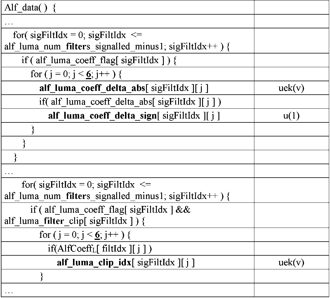
ルナフィルタのALF係数の数は13 になるため、最後の係数フィルタの初期化処理は次のようになる。
filtIdx=0~NumAlfFilters-1における、最後のフィルタ係数AlfCoeffL[filtIdx][6]は以下のように導出される・
AlfCoeffL[filtIdx][6]=128
Since the number of ALF coefficients of the lunar filter is 13, the initialization process of the last coefficient filter is as follows.
The last filter coefficient AlfCoeffL[filtIdx][ 6 ] in filtIdx=0 to NumAlfFilters−1 is derived as follows:
AlfCoeffL[filtIdx][6]=128
ビットストリーム適合性要件では、filtIdx=0~NumAlfFilters-1、j=0~11における、AlfCoeffL[filtIdx][j]は、-2^7~2^7-1内にあり、AlfCoeffL[filtIdx][6]は0~2^8-1の範囲内になければならない。
For bitstream conformance requirements, AlfCoeffL[filtIdx][j], where filtIdx = 0 to NumAlfFilters-1, j = 0 to 11, is within -2^7 to 2^7-1 and AlfCoeffL[filtIdx][ 6 ] must be in the
“ルマサンプルのためのコーディングツリーブロックフィルタリング処理”のための、“ルマサンプルのためのALF転置及びフィルタインデックスの導出”のフィルタインデックスの導出は以下のように修正される(以前に提示されたALFデータシンタックスに対して行われた変更が下線および太字の両方で示され、可能な限り繰り返される部分は省略される)。 For the "Coding Tree Block Filtering Process for Luma Samples", the filter index derivation in "ALF Transpose and Filter Index Derivation for Luma Samples" is modified as follows (previously presented ALF Changes made to data syntax are shown in both underline and bold, with repetitions omitted where possible).
フィルタインデックス節“ALF転置及びルマサンプルのフィルタインデックスの導出プロセス”は、ロケーション(xCtb、yCtb)、および再構成されたルマピクチャサンプルアレイrecPictureLを入力とし、x、y=0~CtSizeY-1におけるfiltIdx[x][y]およびtransposeIdx[x][y]を呼び出される。
The Filter Index clause “Process of Deriving Filter Indexes for ALF Transpose and Luma Samples” takes as input locations (xCtb, yCtb) and the reconstructed luma picture sample array recPictureL, with filtIdx in x, y=0 to
フィルタリングされた再構成輝度サンプルalfPictureL[x][y]の導出のために、現在のルマコーディングツリーブロックrecPictureL[x][y]内の各再構成ルマサンプルは、x、y =0~CtbSizeY-1にて、以下のようにフィルタリングされる。 For the derivation of the filtered reconstructed luminance samples alfPictureL[x][y], each reconstructed luma sample in the current luma coding tree block recPictureL[x][y] is represented by x,y=0 to CtbSizeY− 1 is filtered as follows.
filtIdx[x][y]によって指定されるフィルタに対応するルマフィルタ係数f[j]のアレイ、及び、ルマフィルタクリッピングc[j]のアレイは、j =0~6では以下のように導出される。
f[j]=AlfCoeffL[x][y][j]
c[j]=AlfClipL[x][y][j]
The array of luma filter coefficients f[j] corresponding to the filter specified by filtId x[x][y] and the array of luma filter clippings c[j] are derived for j = 0 to 6 as .
f[j]=AlfCoeffL[x][y][j]
c[j]=AlfClipL[x][y][j]
ルマフィルタ係数filterCoeffおよびフィルタクリッピング値filterClipは、以下のようにtransposeIdx[x][y]に応じて導出される。
transposeIndex[x][y]==1の場合
filterCoeff[]={f[4]、f[1]、f[5]、f[3]、f[0]、f[2]、f[6]}
filterClip[]={c[4]、c[1]、c[5]、c[3]、c[0]、c[2]、c[6]}
そうではなく、transposeIndex[x][y]==2の場合、
filterCoeff[]={f[0]、f[3]、f[2]、f[1]、f[4]、f[5]、f[6]}
filterClip[]={c[0]、c[3]、c[2]、c[1]、c[4]、c[5]、c[6]}
そうではなく、transposeIndex[x][y]==3の場合、
filterCoeff[]={f[4]、f[3]、f[5]、f[1]、f[0]、f[2]、f[6]}
filterClip[]={C[4]、c[3]、c[5]、c[1]、c[0]、c[2]、c[6]}
それ以外の場合
filterCoeff[]={f[0]、f[1]、f[2]、f[3]、f[4]、f[5]、f[6]}
filterClip[]={c[0]、c[1]、c[2]、c[3]、c[4]、c[5]、c[6]}
The luma filter coefficient filterCoeff and the filter clipping value filterClip are derived depending on the transformIdx[x][y] as follows.
if translateIndex[x][y]==1 filterCoeff[]={f[4],f[1],f[5],f[3],f[0],f[2],f[6 ]}
filterClip[]={c[4], c[1], c[5], c[3], c[0], c[2], c[6]}
Otherwise, if translateIndex[x][y]==2,
filterCoeff[]={f[0], f[3], f[2], f[1], f[4], f[5], f[6]}
filterClip[]={c[0], c[3], c[2], c[1], c[4], c[5], c[6]}
Otherwise, if translateIndex[x][y]==3,
filterCoeff[]={f[4], f[3], f[5], f[1], f[0], f[2], f[6]}
filterClip[]={C[4], c[3], c[5], c[1], c[0], c[2], c[6]}
else filterCoeff[]={f[0], f[1], f[2], f[3], f[4], f[5], f[6]}
filterClip[]={c[0], c[1], c[2], c[3], c[4], c[5], c[6]}
ルマサンプルの所与のアレイrecPicture内の対応するルマサンプル(x、y)の各々の位置(hx、vy)は、以下のように導出される。
hx=Clip3(0、pic_width_in_luma_samples-1、xCtb + x)
vy=Clip3(0、pic_height_in_luma_samples - 1、yCtb + y)
The position (hx, vy) of each corresponding luma sample (x, y) in a given array recPicture of luma samples is derived as follows.
hx = Clip3(0, pic_width_in_luma_samples-1, xCtb + x)
vy = Clip3(0, pic_height_in_luma_samples - 1, yCtb + y)
変数currは、以下のように導出される: curr=recPictureL[hx、vy] The variable curr is derived as follows: curr=recPictureL[hx, vy]
変数sumは次のように導出される。
sum= filterCoeff[0]*(Clip3(-filter[0],filterClip[0]、recPictureL[hx、vy + 2]- curr)+Clip3(-filterClip[0]、filterClip[0]、recPictureL[hx、vy-2]-curr))
+ filterCoeff[1]*(Clip3(-filterClip[1]、filterClip[1]、recPictureL[hx+1、vy+1]-curr)+Clip3(-filterClip[1]、filterClip[1]、recPictureL[hx-1、vy-1]-curr))
+ filterCoeff[2]*(Clip3(-filterClip[2]、filterClip[2]、recPictureL[hx、vy+1]-curr)+Clip3(-filterClip[2]、filterClip[2]、recPictureL[hx、vy-1]-curr))
+ filterCoeff[3]*(Clip3(-filterClip[3]、filterClip[3]、recPictureL[hx-1、vy+1]-curr)+Clip3(-filterClip[3]、filterClip[3]、recPictureL[hx+1、vy-1]-curr))
+ filterCoeff[4]*(Clip3(-filterClip[4]、filterClip[4]、recPictureL[hx+2、vy]-curr)+Clip3(-filterClip[4]、filterClip[4]、recPictureL[hx-2、vy]-curr))
+ filterCoeff[5]*(Clip3(-filterClip[5]、filterClip[5]、recPictureL[hx+1、vy]-curr)+Clip3(-filterClip[5]、filterClip[5]、recPictureL[hx-1、vy]-curr))
+ filterCoeff[6]*recPictureL[hx、vy]
The variable sum is derived as follows.
sum=filterCoeff[0]*(Clip3(-filter[0], filterClip[0], recPictureL[hx, vy+2]-curr)+Clip3(-filterClip[0], filterClip[0], recPictureL[hx, vy -2]-curr))
+ filterCoeff[1]*(Clip3(-filterClip[1], filterClip[1], recPictureL[hx+1, vy+1]-curr) + Clip3(-filterClip[1], filterClip[1], recPictureL[hx-1, vy- 1]-curr))
+ filterCoeff[2]*(Clip3(-filterClip[2], filterClip[2], recPictureL[hx, vy+1]-curr) + Clip3(-filterClip[2], filterClip[2], recPictureL[hx, vy-1] -curr))
+ filterCoeff[3]*(Clip3(-filterClip[3], filterClip[3], recPictureL[hx-1, vy+1]-curr) + Clip3(-filterClip[3], filterClip[3], recPictureL[hx+1, vy- 1]-curr))
+ filterCoeff[4]*(Clip3(-filterClip[4], filterClip[4], recPictureL[hx+2, vy]-curr) + Clip3(-filterClip[4], filterClip[4], recPictureL[hx-2, vy] -curr))
+ filterCoeff[5]*(Clip3(-filterClip[5], filterClip[5], recPictureL[hx+1, vy]-curr) + Clip3(-filterClip[5], filterClip[5], recPictureL[hx-1, vy] -curr))
+ filterCoeff[6] * recPictureL[hx, vy]
sum=(sum+64)>>7 sum=(sum+64)>>7
修正されフィルタリングされた再構成ルマ画像サンプルalfPictureL[xCtb+x][yCtb+y]は、以下のように導出される。
alfPictureL[xCtb+x][yCtb+y]=Clip3(0、(1<<BitDepthY)-1、sum)
The modified filtered reconstructed luma image sample alfPictureL[xCtb+x][yCtb+y] is derived as follows.
alfPictureL[xCtb+x][yCtb+y]=Clip3(0, (1<<BitDepthY)-1, sum)
近傍と中心との間の差異を使用しない変形例では、k=0~5において、AlfCoeffL[filtIdx][6]=128-Σk(AlfCoeffL[filtIdx][k])が使用される。フィルタリングでは、フィルタリングのクリッピングパラメータと同様の変更も行われる。 A variant that does not use the difference between the neighborhood and the center uses AlfCoeffL[filtIdx][6]=128−Σ k (AlfCoeffL[filtIdx][k]) for k=0-5. Filtering also makes similar changes to filtering clipping parameters.
別の変形例では、フィルタのために7×7ダイヤモンド形状を使用するが、ルマフィルタのために図16-aのクリッピングパターン1601、クロマフィルタのために図16-bのクリッピングパターン1605を使用して、テーブル4の非線形ALFデータシンタックスは以下のように修正される(以前に例示されたテーブル4のALFデータシンタックスに行われた変更、両方とも下線および太字であり、可能な限り繰り返される部分は省略される)。

AlfClipPatL[]は、Lumaフィルタの定数クリッピングパターンテーブルであり、以下のように設定される:
AlfClipPatL[]={0、0、1、0、0、0、1、0、0、0、1、1}
AlfClipPatL[ ] is the constant clipping pattern table for the Luma filter and is set as follows:
AlfClipPatL[ ]={0, 0, 1, 0, 0, 0, 1, 0, 0, 0, 1, 1}
AlfClipPatC[]はChromaフィルタの定数クリッピングパターンテーブルであり、以下のように設定される:
AlfClipPatC[]={1、1、0、1、1、0}
AlfClipPatC[] is the constant clipping pattern table for the Chroma filter and is set as follows:
AlfClipPatC[]={1, 1, 0, 1, 1, 0}
セマンティクスの一部は、以下のように修正される。
- “ルマサンプルのためのコーディングツリーブロックフィルタリングプロセス”における変数sumは、以下のように導出される.
sum=filterCoeff[0]*(recPictureL[hx、vy+3]-curr + recPicture[hx、vy-3]-curr)
+filterCoeff[1]*(recPicure[hx+1、vy+2]-curr)+recPictureL[hx-1、vy-2]-curr)
+filterCoeff[2]*(Clip3(-filterClip[2]、filterClip[2]、recPictureL[hx、vy+2]-curr)+Clip3(-filterClip[2]、filterClip[2]、recPictureL[hx、vy-2]-curr))
+ filterCoeff[3]*(recPictureL[hx-1、vy+2]-curr+recPictureL[hx+1、vy-2]-curr)
+ filterCoeff[4]*(recPictureL[hx+2、vy+1]-curr+recPictureL[hx-2、vy-1]-curr)
+ filterCoeff[5]*(recPictureL[hx+1、vy+1]-curr+recPictureL[hx-1、vy-1]-curr)
+ filterCoeff[6]*(Clip3(-filterClip[6]、filterClip[6]、recPictureL[hx、vy+1]-curr)+Clip3(-filterClip[6]、filterClip[6]、recPictureL[hx、vy-1]-curr))
+ filterCoeff[7]*(recPictureL[hx-1、vy+1]-curr+recPictureL[hx+1、vy-1]-curr)
+ filterCoeff[8]*(recPictureL[hx-2、vy+1]-curr+recPictureL[hx+2、vy-1]-curr)
+ filterCoeff[9]*(recPictureL[hx+3、vy]-curr+recPictureL[hx-3、vy]-curr)
+filterCoeff[ 10]*(Clip3(-filterClip[10]、filterClip[10]、recPictureL[hx+2、vy]-curr)+Clip3(-filterClip[10]、filterClip[10]、recPictureL[hx-2、vy]-curr))
+filterCoeff[ 11]*(Clip3(-filterClip[11]、filterClip[11]、recPictureL[hx+1、vy]-curr)+Clip3(-filterClip[11]、filterClip[11]、recPictureL[hx-1、vy]-curr))
+filterCoeff[ 12]*recPictureL[hx、vy]
Some of the semantics are modified as follows.
- The variable sum in the "coding tree block filtering process for luma samples" is derived as follows.
sum=filterCoeff[0]*(recPictureL[hx, vy+3]-curr + recPicture[hx, vy-3]-curr)
+filterCoeff[1]*(recPicture[hx+1,vy+2]-curr)+recPictureL[hx-1,vy-2]-curr)
+filterCoeff[2]*(Clip3(-filterClip[2], filterClip[2], recPictureL[hx, vy+2]-curr)+Clip3(-filterClip[2], filterClip[2], recPictureL[hx, vy-2]- curr))
+ filterCoeff[3]*(recPictureL[hx-1,vy+2]-curr + recPictureL[hx+1,vy-2]-curr)
+ filterCoeff[4]*(recPictureL[hx+2, vy+1]-curr + recPictureL[hx-2, vy-1]-curr)
+ filterCoeff[5]*(recPictureL[hx+1, vy+1]-curr + recPictureL[hx-1, vy-1]-curr)
+ filterCoeff[6]*(Clip3(-filterClip[6], filterClip[6], recPictureL[hx, vy+1]-curr) + Clip3(-filterClip[6], filterClip[6], recPictureL[hx, vy-1] -curr))
+ filterCoeff[7]*(recPictureL[hx-1, vy+1]-curr + recPictureL[hx+1, vy-1]-curr)
+ filterCoeff[8]*(recPictureL[hx-2, vy+1]-curr + recPictureL[hx+2, vy-1]-curr)
+ filterCoeff[9]*(recPictureL[hx+3,vy]-curr + recPictureL[hx-3,vy]-curr)
+filterCoeff[10]*(Clip3(-filterClip[10], filterClip[10], recPictureL[hx+2, vy]-curr)+Clip3(-filterClip[10], filterClip[10], recPictureL[hx-2, vy]- curr))
+filterCoeff[11]*(Clip3(-filterClip[11], filterClip[11], recPictureL[hx+1, vy]-curr)+Clip3(-filterClip[11], filterClip[11], recPictureL[hx-1, vy]- curr))
+filterCoeff[12]*recPictureL[hx, vy]
sum=(sum+64)>>7 sum=(sum+64)>>7
“クロマサンプルのためのコーディングツリーブロックフィルタリング処理」における変数sumは、以下のように導出される。
sum=AlfCoeffC[0]*(Clip3(-AlfClipC[0]、AlfClipC[0]、recPicture[hx、vy+2]-curr)+Clip3(-AlfClipC[0]、AlfClipC[0]、recPicture[hx、vy-2]-curr))
+AlfCoeffC[1]*(Clip3(-AlfClipC[1]、AlfClipC[1]、recPicture[hx+1、vy+1]-curr)+Clip3(-AlfClipC[1]、AlfClipC[1]、recPicture[hx-1、vy-1]-curr))
+AlfCoeffC[2]*(recPicture[hx、vy+1]-curr+recPicture[hx、vy-1]-curr)
+AlfCoeffC[3]*(Clip3(-AlfClipC[3]、AlfClipC[3]、recPicture[hx-1、vy+1]-curr)+Clip3(-AlfClipC[3]、AlfClipC[3]、recPicture[hx+1、vy-1]-curr))
+AlfCoeffC[4]*(Clip3(-AlfClipC[4]、AlfClipC[4]、recPicture[hx+2、vy]-curr)+Clip3(-AlfClipC[4]、AlfClipC[4]、recPicture[hx-2、vy]-curr))
+AlfCoeffC[5]*(recPicture[hx+1、vy]-curr+recPicture[hx-1、vy]-curr)
+AlfCoeffC[6]*recPicture[hx、vy]
The variable sum in the “coding tree block filtering process for chroma samples” is derived as follows.
sum = AlfCoeffC[0]*(Clip3(-AlfClipC[0], AlfClipC[0], recPicture[hx, vy+2]-curr) + Clip3(-AlfClipC[0], AlfClipC[0], recPicture[hx, vy-2 ]-curr))
+AlfCoeffC[1]*(Clip3(-AlfClipC[1], AlfClipC[1], recPicture[hx+1, vy+1]-curr) + Clip3(-AlfClipC[1], AlfClipC[1], recPicture[hx-1, vy-1 ]-curr))
+AlfCoeffC[2]*(recPicture[hx, vy+1]-curr + recPicture[hx, vy-1]-curr)
+AlfCoeffC[3]*(Clip3(-AlfClipC[3], AlfClipC[3], recPicture[hx-1, vy+1]-curr) + Clip3(-AlfClipC[3], AlfClipC[3], recPicture[hx+1, vy-1 ]-curr))
+AlfCoeffC[4]*(Clip3(-AlfClipC[4], AlfClipC[4], recPicture[hx+2, vy]-curr) + Clip3(-AlfClipC[4], AlfClipC[4], recPicture[hx-2, vy]- curr))
+AlfCoeffC[5]*(recPicture[hx+1,vy]-curr +recPicture[hx-1,vy]-curr)
+AlfCoeffC[6] *recPicture[hx, vy]
他のクリッピングパターンを使用する他の変形形態は、前述の変形形態から容易に導出することができることが理解される。同様に、クリッピングの数を減らす(すなわち、クリッピング位置を減らす、すなわち、式(17)および図7のように、ルマ成分についてはクリッピング無しが、“f[12]”無し、“c[12]”無し、“filterCoeff[12]”無し、及び、“(sum=curr+(sum+64)>>7)”無しとなるように、現在(中心)サンプル値“curr”に適用される)、及び/又は、隣接サンプルと中心サンプルとの間の差を使用しない変形例も導出することができる。 It is understood that other variations using other clipping patterns can be readily derived from the variations described above. Similarly, reduce the number of clippings (i.e. reduce the clipping positions, i.e. no clipping for the luma component, but no "f[12]", "c[12] "none," none "filterCoeff[12]", and "(sum=curr+(sum+64)>>7)" applied to the current (center) sample value "curr" to be none), and/or , a variant that does not use the difference between the neighboring samples and the central sample can also be derived.
図8は、本発明の一実施形態に従った、図7のフィルタの非線形部分が無効にされたときに得られる線形フィルタのブロック図である。一実施形態によれば、ALFがアクティブであり、非線形ALFが非アクティブである場合、フィルタリングのために線形ALFが使用される。このような実施形態の変形例では、非線形ALFが(7)式で定義され、図7に図示されるように使用され、(4)式で定義され、図6に図示されるような線形ALFを使用する代わりに、式(6)で定義され、図8に図示されるように線形フィルタリングが実行される。ハードウェア設計では、非線形フィルタと線形フィルタとの間の共通回路部品を共有することが可能になる。図7と図8を比較すると、最小/最大演算は単にバイパスされ、サンプル値に直接進む。このアプローチを使用するもう1つの利点は、エンコーダがフィルタを設計する際に、各フィルタのすべてのフィルタ係数の合計が1であることを確実にする必要がないことである。このデザインの結果、現在のサンプルを除き、係数ごとに1つの減算を加え、現在のサンプルに対して1つの乗算を除去できるいうことである。 FIG. 8 is a block diagram of the linear filter obtained when the non-linear portion of the filter of FIG. 7 is disabled, according to one embodiment of the present invention. According to one embodiment, linear ALF is used for filtering when ALF is active and non-linear ALF is inactive. In a variation of such an embodiment, a non-linear ALF as defined in equation (7) and illustrated in FIG. 7 is used, and a linear ALF as defined in equation (4) and illustrated in FIG. Instead of using , linear filtering is performed as defined in equation (6) and illustrated in FIG. The hardware design allows sharing common circuit components between nonlinear and linear filters. Comparing Figures 7 and 8, the min/max operation is simply bypassed and goes directly to the sample values. Another advantage of using this approach is that the encoder does not need to ensure that all filter coefficients in each filter sum to unity when designing the filters. A consequence of this design is that one subtraction can be added for each coefficient except for the current sample, and one multiplication can be eliminated for the current sample.
図7の設計はまた、クリッピングパラメータがとり得る最大値が十分に低い場合に、乗算を実施するためのハードウェアビットを節約するという利点を有する。 The design of FIG. 7 also has the advantage of saving hardware bits to perform the multiplication if the maximum possible value of the clipping parameter is low enough.
一実施形態によれば、図5のスライスヘッダ内にシグナリングされるALFのシンタックス要素は、もはやスライスヘッダでシグナリングされず、代わりに、例えばピクチャヘッダでフレームレベルでシグナリングされる。次に、スライスヘッダ内に、フレームレベルで提供されるパラメータがスライス内で直接使用されること、もしくは、フレームレベルで提供されるパラメータが“フレッシュ”(すなわち、更新されること)されなければならないことをシグナルするための1つまたは複数のフラグ/シンタックス要素がある。スライスレベルでの、このリフレッシュは、スライスヘッダ内にて行われる。フィルタ係数および/またはクリッピングパラメータのリフレッシュは、フレームレベルで示される値とスライスで使用する値との間の差を符号化することによって行われる。一実施形態によれば、スライスヘッダ内の追加のシンタックス要素は、フィルタ係数および/またはクリッピングパラメータの値がスライスヘッダ内で差分として符号化されているかどうか、またはそれらの値が符号化されているかどうかを示す。 According to one embodiment, the ALF syntax elements signaled in the slice header of FIG. 5 are no longer signaled in the slice header, but instead are signaled at the frame level, eg, in the picture header. Then, in the slice header, either the parameters provided at the frame level must be used directly in the slice, or the parameters provided at the frame level must be "freshed" (i.e. updated). There are one or more flags/syntax elements to signal that. At the slice level, this refresh is done in the slice header. Refreshing the filter coefficients and/or clipping parameters is done by encoding the difference between the value indicated at the frame level and the value used in the slice. According to one embodiment, an additional syntax element in the slice header is whether the values of the filter coefficients and/or clipping parameters are differentially encoded in the slice header, or whether their values are encoded in the slice header. indicates whether or not
一実施形態によれば、(スライスヘッダ内の)スライスレベルで定義されたフィルタ係数および/またはクリッピングパラメータは、(例えば、各CTUについて)より細かい粒度レベル(granularity level)で更新することができる。更新が実行されるべきかどうかを示すシンタックス要素は、更新が実行されなければならないことを示すときに、更新データだけでなく、スライスデータ内でエントロピー符号化される。一実施形態では、符号化ビットストリームにおいて、各CTUについて、符号化されたスライスデータは、ルマフィルタ/クリッピングパラメータを更新する必要があるかどうかを示すエントロピー符号化されたフラグを1つ含む。フラグが更新が行われるべきであることを示す場合、フィルタ係数の各テーブルについて、エントロピー符号化フラグはフィルタが更新されなければならないかどうかを示す。フィルタを更新しなければならない場合、係数のオフセット(スライス内の基準値との差、または同じスライスに属する以前に符号化されたCTU内の基準値との差)および/またはクリッピングパラメータのオフセットはエントロピー符号化される。 According to one embodiment, filter coefficients and/or clipping parameters defined at the slice level (in the slice header) may be updated at a finer granularity level (eg, for each CTU). A syntax element indicating whether an update should be performed is entropy encoded in the slice data as well as the update data when indicating that an update should be performed. In one embodiment, in the coded bitstream, for each CTU, the coded slice data contains one entropy coded flag indicating whether the luma filter/clipping parameters need to be updated. For each table of filter coefficients, the entropy coding flag indicates whether the filter should be updated, if the flag indicates that an update should be performed. If the filter has to be updated, the coefficient offset (difference from the reference value within the slice or from the reference value within a previously coded CTU belonging to the same slice) and/or the clipping parameter offset is Entropy encoded.
一実施形態によれば、エンコーダの観点から、図9を参照して説明したVTM-3.0のALF符号化プロセスの主な論理ステップが維持される。主な変更は、フィルタを構築するために抽出される統計の性質、およびフィルタが決定される方法である。
単純なウィーナーフィルタ(Wiener Filter)演算の代わりに、クリッピングパラメータを繰り返し最適化して、最良のクリッピングパラメータ及び関連する非線形Wウィーナーフィルタ係数を見つる。
According to one embodiment, from the encoder's perspective, the main logical steps of the VTM-3.0 ALF encoding process described with reference to FIG. 9 are preserved. The main changes are the nature of the statistics extracted to build the filters and the way the filters are determined.
Instead of a simple Wiener Filter operation, we iteratively optimize the clipping parameters to find the best clipping parameters and associated non-linear W Wiener filter coefficients.
一実施形態によれば、我々はNK、1つのクリッピングパラメータが取ることができる値の数の限界を定義する。NKは小さくでき、例えば、NK=12もしくは、それ以下である。次に、ステップ902において、共分散および相互共分散行列統計を計算する代わりに、エンコーダは、NK×NKクリッピング共分散行列統計の2エントリテーブルE、および、NKクリッピング相互共分散行列統計の1エントリテーブルyを構築する(1つの共分散行列統計および1つの相互共分散行列統計の代わりに)。
According to one embodiment, we define N K , the limit on the number of values that one clipping parameter can take. N K can be small, eg, N K =12 or less. Next, in
クリッピング共分散行列Ec[a][b]は、

クリッピング相互共分散行列yC[C]は、所望のフィルター出力(すなわち、オリジナルサンプル)の実現値とXCの実現値との間の相互共分散行列である。 The clipping cross-covariance matrix y C [C] is the cross-covariance matrix between the realizations of the desired filter output (ie, the original samples) and the realizations of X C .
我々は、


我々は、i<Nc,j<NCであり、k<Ncであるときのy[k]=yc[C[k]][k]について、E[i,j]=EC[C[i]][C[j]][i,j]となるクリッピングパラメータの共分散行列Eおよび相互共分散行列yを算出する。次に、我々は、線形ALFについて前述したように、この2つの行列を用いてウィナーフィルタを構築する。
we,
We have E [ i ,j] = EC Calculate the covariance matrix E and the cross-covariance matrix y of the clipping parameters [C[i]][C[j]][i,j]. We then use the two matrices to construct a Wiener filter as described above for linear ALF.
ステップ904にて、共分散行列と相互共分散行列の統計を組合せる代わりに、エンコーダは、各クリッピング-共分散行列とクリッピング-相互共分散行列の統計を組合せる(ここでも、この組合せは、統計を合計することによって行われる)。
At
ステップ905にて、フィルタの最適化されたグループ(すなわち、最適化されたマージされたフィルタ)を見つけるために使用される方法は、以前と同様である。主な違いは、試験/比較された各フィルタについて、ただ1つのウィーナーフィルタを計算する代わりに、クリッピングパラメータが反復的に最適化され、各ステップは特定のクリッピングパラメータについてウィーナーフィルタを計算し、フィルタの出力誤差(統計行列上で計算される)を最小化することである。単純な最適化アルゴリズムは、すべてのクリッピングパラメータ値(Ci)がゼロに設定される(または中央クリッピング値または任意のデフォルト値に設定される)から開始し、次いで、ループ内の以下のステップに従い、フィルタを改善(すなわち、出力誤差を低減する)していくことである:各クリッピングパラメータ値について、利用可能/許可される場合、次のクリッピングパラメータ値をとり(すなわち、インデックス<最大インデックス値)、このクリッピングパラメータ値を用いて計算されたウィーナーフィルタがより良好である場合、このクリッピングパラメータ値を用いて計算されたウィーナーフィルタは利用可能/許可される場合(すなわち、インデックス>0)、このクリッピングパラメータ値を用いて計算されたウィーナーフィルタがより良好である。2つのフィルタをグループ化する場合、1つの戦略は、各クリッピングパラメータ値が2つのフィルタの各クリッピングパラメータ値の平均に設定された状態で最適化を開始することであり得る。
The method used to find the optimized group of filters (ie, the optimized merged filters) in
ステップ906、907、908、909、910および911には、実際の変更はない。
ステップ912にて、結合された統計変更はステップ904について説明したものと同じである。ステップ913におけるクロマフィルタの決定は、ステップ905について説明したフィルタ最適化に対応する。ALFパラメータが各フィルタについて決定されたクリッピングパラメータを含むステップ918を除いて、他のステップは変更されない。
At
「通常の」ALFを用いるVTM-3.0では、エンコーダが浮動小数点値から整数フィルタ係数を導出するとき、エンコーダは最初に浮動小数点値の固定小数点値への量子化を実行する:各フィルタ係数について、フィルタ係数乗算を固定小数点精度で最も近い整数値に丸めることに留意されたい。次に、フィルタ係数を反復的に調整して(丸め誤差を補正するために)、フィルタ効率を改善しようとする。また、エンコーダは、すべてのフィルタ係数の合計が(固定小数点精度で乗算された)1に等しく、中心サンプルのフィルタ係数が最大値を超えないことを保証しなければならない(乗算におけるその使用があまり多くのビットを使用することにならないことを保証するため)。 In VTM-3.0 with "normal" ALF, when the encoder derives integer filter coefficients from floating point values, the encoder first performs a quantization of the floating point values to fixed point values: each filter coefficient , rounding the filter coefficient multiplications to the nearest integer value in fixed-point precision. The filter coefficients are then iteratively adjusted (to compensate for rounding errors) in an attempt to improve filter efficiency. Also, the encoder must ensure that the sum of all filter coefficients (multiplied with fixed-point precision) is equal to 1, and that the filter coefficient of the center sample does not exceed the maximum value (its use in multiplication is to ensure that you don't end up using a lot of bits).
隣接サンプルとの差がフィルタの入力として使用される本発明の実施形態では、中心係数が常に1であるので、それが最大値を超えないことを確実にする必要はない。また、全てのフィルタ係数の和の値を追跡する必要もない。 In embodiments of the invention where the difference between adjacent samples is used as the filter input, the center coefficient is always 1, so there is no need to ensure that it does not exceed a maximum value. Also, there is no need to keep track of the value of the sum of all filter coefficients.
これらの実施形態の利点は、符号化効率の改善である。
これらの実施形態の説明はルマ成分およびクロマ成分に言及しているが、それらは単一のルマ成分またはRGB成分などの他の成分に容易に適合させることができる。
An advantage of these embodiments is improved coding efficiency.
Although the descriptions of these embodiments refer to luma and chroma components, they can be easily adapted to other components such as a single luma component or RGB components.
前述の実施形態または変形例では、本発明が、図3-aおよび図4-aの304および407のフィルタリングを修正して、フィルタ入力に非線形関数を使用して非線形フィルタリング効果を得る。図2はまた、非線形関数のための追加のパラメータをシグナリングするための新しいシンタックス要素を追加するように修正される(実施形態の一例を図5を参照して説明した)。暗黙のうちに、302および402における入力フィルタリングパラメータは、非線形関数のための追加パラメータをさらに含むように修正される。最後に、303および406におけるフィルタ導出は修正され、フィルタに対する非線形関数を導出する(すなわち、「非線形フィルタ」を導出する)。従って、ほとんどの状況において、出力画像部分305及び408は、VTM-3.0において生成されるものと同じではなく、等価/比較可能な入力サンプルに対してより高い品質を有し、及び/又は出力画質と符号化効率との間のより良い妥協を達成する。別の実施形態/変形形態では、ALF自体が前述の非線形関数のいずれかを使用してフィルタリングするように動作するように修正されることを理解されたい。
In the above embodiments or variations, the present invention modifies the filtering of 304 and 407 of FIGS. 3a and 4a to use a nonlinear function on the filter input to obtain a nonlinear filtering effect. FIG. 2 is also modified to add new syntax elements for signaling additional parameters for non-linear functions (an example embodiment was described with reference to FIG. 5). Implicitly, the input filtering parameters at 302 and 402 are modified to further include additional parameters for non-linear functions. Finally, the filter derivation at 303 and 406 is modified to derive a nonlinear function for the filter (ie, derive a "nonlinear filter"). Therefore, in most situations, the
本発明の実施形態の実施
前述の実施形態のうちの1つまたは複数は、1つまたは複数の前述の実施形態の方法ステップを実行するエンコーダまたはデコーダの形態で実装され得る。以下の実施形態は、そのような実装を例示する。
Implementation of Embodiments of the Invention One or more of the foregoing embodiments may be implemented in the form of an encoder or decoder that performs the method steps of one or more of the foregoing embodiments. The following embodiments exemplify such implementations.
例えば、前述の実施形態のいずれかによるアダプティブループフィルタは、図10のエンコーダによって実行されるポストフィルタリング9415、または図11のデコーダによって実行されるポストフィルタリング9567において使用され得る。 For example, an adaptive loop filter according to any of the foregoing embodiments may be used in post-filtering 9415 performed by the encoder of FIG. 10 or post-filtering 9567 performed by the decoder of FIG.
図10は、本発明の一実施形態によるエンコーダのブロック図を示す。エンコーダは、接続されたモジュールによって表され、各モジュールは例えば、デバイスの中央処理装置(CPU)によって実行されるべきプログラム命令の形態で、本発明の1つまたは複数の実施形態による画像シーケンスの画像を符号化する少なくとも1つの実施形態を実施する方法の少なくとも1つの対応するステップを実施するように適合される。 FIG. 10 shows a block diagram of an encoder according to one embodiment of the invention. The encoder is represented by connected modules, each of which, for example, in the form of program instructions to be executed by the central processing unit (CPU) of the device, encodes images of an image sequence according to one or more embodiments of the present invention. is adapted to perform at least one corresponding step of a method of implementing at least one embodiment of encoding the
9401のデジタル画像i0~inのオリジナルシーケンスは、エンコーダ9400によって入力として受信される。各デジタル画像は、時には画素(以下、画素と呼ぶ)とも呼ばれるサンプルのセット(集合)によって表される。ビットストリーム9410は、符号化プロセスの実施後にエンコーダ9400によって出力される。ビットストリーム9410は、複数の符号化単位またはスライスのような画像部分のためのデータを含み、各スライスは、スライスを符号化するために使用される符号化パラメータの符号化値を送信するためのスライスヘッダと、符号化されたビデオデータを含むスライス本体とを含む。
An original sequence of digital images i 0 -in at 9401 is received as input by
9401の入力デジタル画像i0~inは、モジュール9402によってピクセルのブロックに分割される。ブロックは画像部分に対応し、可変サイズであってもよい(例えば、4×4、8×8、16×16、32×32、64×64、128×128ピクセル、および、いくつかの矩形ブロックサイズも考慮することができる)。符号化モードは、各入力ブロックに対して選択される。空間予測符号化(イントラ予測)に基づく符号化モードと、時間予測に基づく符号化モード(インター符号化、MERGE、SKIP)との2つの符号化モードのファミリが提供される。可能な符号化モードがテストされる。
An input digital image i 0 -in at 9401 is divided into blocks of pixels by
モジュール9403は、符号化されるべき所与のブロックが当該符号化されるべき前記ブロックの近傍の画素から計算された予測子によって予測されるイントラ予測処理を実施する。選択されたイントラ予測子の指示、および所与のブロックとその予測子との間の差は、イントラ符号化が選択された場合に残差を提供するために符号化される。
時間的予測は、動き推定モジュール9404および動き補償モジュール9405によって実施される。最初に、参照画像9416のセットの中から参照画像が選択され、符号化されるべき所与のブロックに最も近いエリア(画素値類似性に関して最も近い)で参照エリアまたは画像部分とも呼ばれる参照画像の部分が、動き推定モジュール9404によって選択される。次に、動き補償モジュール9405は、選択された領域を使用して、符号化されるブロックを予測する。選択された参照領域と所与のブロックとの間の差は、残差ブロック/データとも呼ばれ、動き補償モジュール9405によって計算される。選択された参照領域は動き情報(例えば、動きベクトル)を用いて示される。
Temporal prediction is performed by
したがって、両方の場合(空間的予測および時間的予測)において、SKIPモードになり場合は、残差はオリジナルのブロックから予測を減算することによって計算される。 Therefore, in both cases (spatial prediction and temporal prediction), if SKIP mode is entered, the residual is computed by subtracting the prediction from the original block.
モジュール9403によって実施されるINTRA予測では、予測方向が符号化される。モジュール9404、9405、9416、9418、9417によって実施されるインター予測では、少なくとも1つの動きベクトルまたは、そのような動きベクトルを識別するための情報(データ)が時間予測のために符号化される。インター予測が選択された場合、動きベクトルおよび残差ブロックに関連する情報が符号化される。ビットレートをさらに低減するために、動きが均一であると仮定すると、動きベクトルは、動きベクトル予測子に対する差によって符号化される。1組の動き情報予測子候補からの動きベクトル予測子は、動きベクトル予測符号化モジュール9417によって動きベクトルフィールド9418から得られる。
The INTRA prediction performed by
エンコーダ9400は、さらに、レート歪み基準などの符号化コスト基準を適用することによって、符号化モードを選択するための選択モジュール9406を含む。冗長性をさらに低減するために、変換モジュール9407によって変換(DCTなど)が残差ブロックに適用され、得られた変換データは、次いで、量子化モジュール9408によって量子化され、エントロピー符号化モジュール9409によってエントロピー符号化される。最後に、SKIPモードになく、選択された符号化モードは残差ブロックの符号化を必要とする場合には、符号化されている現在のブロックの符号化された残差ブロックはビットストリーム9410に挿入される。
Encoder 9400 further includes a
エンコーダ9400は、後続の画像の動き推定のための参照画像(例えば、参照画像/ピクチャ9416内のもの)を生成するために、符号化された画像の復号も行う。これにより、ビットストリームを受信するエンコーダ及びデコーダが同じ参照フレームを有することを可能にする(例えば、再構成された画像又は再構成された画像部分が使用される)。逆量子化(「逆量子化」)モジュール9411は、量子化されたデータの逆量子化(「逆量子化」)を実行し、その後、逆変換モジュール9412によって実行される逆変換が続く。イントラ予測モジュール9413は、予測情報を使用して、所与のブロックにどの予測を使用すべきかを決定し、動き補償モジュール9414は、モジュール9412によって得られた残差を、参照画像9416の設定から得られた参照領域に実際に加算する。その後、モジュール9415によってポストフィルタリングが適用され、画素の再構成フレーム(画像または画像部分)をフィルタリングして、参照画像9416のセットの別の参照画像を得る。
Encoder 9400 also decodes the encoded images to generate reference images (eg, those in reference images/pictures 9416) for motion estimation of subsequent images. This allows the encoder and decoder receiving the bitstream to have the same reference frame (eg, the reconstructed image or reconstructed image portion is used). An inverse quantization (“inverse quantization”)
図11は、本発明の一実施形態による、エンコーダからデータを受信するために使用され得るデコーダ9560のブロック図を示す。デコーダは、接続されたモジュールによって表され、各モジュールは例えば、デバイスのCPUによって実行されるプログラム命令の形成で、デコーダ9560によって実装される方法の対応するステップを実装するように構成される。
FIG. 11 shows a block diagram of a
受信するデコーダ9560は、符号化単位(例えば、画像部分、ブロックまたは符号化単位に対応するデータ)を含むビットストリーム9561を受信する。各符号化単位は、符号化パラメータに関する情報を含むヘッダと、符号化されたビデオデータを含むボディとから構成される。図10に関して説明したように、符号化されたビデオデータはエントロピー符号化され、動き情報(例えば、動きベクトル予測子のインデックス)は所与の画像部分(例えば、ブロックまたはCU)について、所定のビット数で符号化される。受信された符号化ビデオデータは、モジュール9562によってエントロピーデコードされる。次いで、残留データは、モジュール9563によって逆量子化され、次いで、逆変換がモジュール9564によって適用され、ピクセル値が得られる。
A receiving
符号化モードを示すモードデータもエントロピーデコードされ、このモードに基づいて、画像データの符号化ブロック(単位/セット/グループ)に対してINTRAタイプデコードまたはINTERタイプデコードが行われる。INTRAモードの場合、ビットストリームにおいて指定されたイントラ予測モードに基づき、イントラ予測子がイントラ予測モジュール9565によって決定される(例えば、イントラ予測モードは、ビットストリームにおいて提供されるデータを使用して決定可能である)。モードがINTERモードである場合、エンコーダによって使用される参照領域を見つける(識別する)ために、動き予測情報がビットストリームから抽出/取得される。動き予測情報は、例えば、参照フレームインデックスと、動きベクトル残差とを含む。動きベクトル予測子は、動きベクトル復号モジュール9570によって動きベクトル残差に加算され、動きベクトルが得られる。
Mode data indicating the encoding mode is also entropy decoded, and based on this mode, INTRA type decoding or INTER type decoding is performed on the encoding block (unit/set/group) of the image data. For INTRA mode, intra predictors are determined by the
動きベクトル復号モジュール9570は、動き予測によって符号化された各画像部分(例えば、現在のブロックまたはCU)に対して動きベクトル復号を適用する。現在のブロックの動きベクトル予測子のインデックスが得られると、画像部分(例えば、現在のブロックまたはCU)に関連する動きベクトルの実際の値が復号され、モジュール9566によって動き補償を適用するために使用することができる。復号された動きベクトルによって示される参照画像部分が、モジュール9566が動き補償を実行することができるように、参照画像9568の設定から抽出/取得される。動きベクトルフィールドデータ9571は、後に復号される動きベクトルの予測に使用されるために、復号された動きベクトルで更新される。
Motion
最後に、復号されたブロックが得られる。適切には、ポストフィルタリングがポストフィルタリングモジュール9567によって適用される。デコードされたビデオ信号9569が、デコーダ9560によって、最終的に得られ、提供される。
Finally, we have the decoded block. Suitably post-filtering is applied by
図12は、本発明の1つまたは複数の実施形態を実施することができるデータ通信システムを示す。データ通信システムは、データ通信ネットワーク9200を介して、データストリーム9204のデータパケットを受信装置、この場合はクライアント端末9202に送信するように動作可能な送信装置、この場合はサーバ9201を含む。データ通信ネットワーク9200は、ワイドエリアネットワーク(WAN)またはローカルエリアネットワーク(LAN)であってもよい。このようなネットワークは例えば、無線ネットワーク(WiFi/802.11aまたはbまたはg)、イーサネットネットワーク、インターネットネットワーク、または複数の異なるネットワークから構成される混合ネットワークであってもよい。本発明の特定の実施形態では、データ通信システムがサーバ9201が同じデータコンテンツを複数のクライアントに送信するデジタルテレビ放送システムであってもよい。
FIG. 12 illustrates a data communication system in which one or more embodiments of the invention can be implemented. The data communication system includes a transmitting device, in this
サーバ9201によって提供されるデータストリーム9204は、ビデオおよびオーディオデータを表すマルチメディアデータから構成されてもよい。オーディオおよびビデオデータストリームは、本発明のいくつかの実施形態ではそれぞれマイクロフォンおよびカメラを使用してサーバ9201によってキャプチャされ得る。いくつかの実施形態において、データストリームはサーバ9201上に記憶されてもよく、あるいは別のデータプロバイダからサーバ9201によって受信されてもよく、あるいはサーバ9201で生成されてもよい。サーバ9201は特に、エンコーダへの入力として提示されるデータのよりコンパクトな表現である送信のための圧縮ビットストリームを提供するために、ビデオストリームおよびオーディオストリームを符号化するためのエンコーダを備える。伝送されるデータの品質対伝送されるデータの量のより良好な比を得るために、ビデオデータの圧縮は例えば、高効率ビデオ符号化(HEVC)フォーマット、またはH.264/Advanced Video Coding(Advanced video Coding)フォーマット、またはVersatile Video Coding(VVC)フォーマットに従ってもよい。クライアント9202は、送信されたビットストリームを受信し、再構成されたビットストリームをデコードして、表示装置上でビデオ画像を再生し、スピーカによってオーディオデータを再生する。
The
この実施形態ではストリーミングシナリオが考慮されるが、本発明のいくつかの実施形態では、エンコーダとデコーダとの間のデータ通信が例えば、光ディスクなどの媒体記憶デバイスを使用して実行され得ることが理解されるのであろう。本発明の1つまたは複数の実施形態では、ビデオ画像が画像の再構成されたピクセルに適用して最終画像内にフィルタリングされたピクセルを提供するために、補償オフセットを表すデータと共に送信され得る。 Although streaming scenarios are considered in this embodiment, it is understood that in some embodiments of the invention data communication between encoders and decoders may be performed using media storage devices such as optical discs, for example. It will be done. In one or more embodiments of the present invention, a video image may be transmitted with data representing a compensating offset to apply to the reconstructed pixels of the image to provide filtered pixels in the final image.
図13は、本発明の少なくとも1つの実施形態を実施するように構成された処理装置9300を概略的に示す。処理装置9300は、マイクロコンピュータ、ワークステーション、ユーザ端末、またはライトポータブル装置などの装置とすることができる。デバイス/装置9300は、通信バス9313を備え、これは以下の構成が接続される:
- マイクロプロセッサのよう、CPUとして示される中央演算装置9311;
- デバイス9300を動作させるための、および/または本発明を実施するためのコンピュータプログラム/命令を格納するための、ROMとして示される、読み出し専用メモリ9307;
- 本発明の実施形態の実行可能コード、ならびに本発明の実施形態に係るデジタル画像のシーケンスを符号化する方法および/またはビットストリームを復号する方法を実現するために必要な変数およびパラメータを記録するように構成されたレジスタを記憶するための、RAMと示される、ランダムアクセスメモリ9312と、
- 処理されるデジタルデータが送信または受信される通信ネットワーク9303に接続された通信インターフェース9302。
Figure 13 schematically illustrates a
- a
- a read-
- records the executable code of embodiments of the invention and the variables and parameters necessary to implement a method of encoding a sequence of digital images and/or a method of decoding a bitstream according to embodiments of the invention; a
- a
オプションで、装置9300は、以下の構成要素を含むこともできる:
- 本発明の1つまたは複数の実施形態の方法を実施するためのコンピュータプログラム、および本発明の1つまたは複数の実施形態の実施中に使用または生成されるデータを記憶するための、ハードディスクなどのデータ記憶手段9304;
- ディスク9306(例えば記憶媒体)のためのディスクドライブ9305、ここでディスク駆動9305は、ディスク9306からデータを読み取るか、またはディスク9306にデータを書き込むように構成されている。または、
- キーボード9310、タッチスクリーン、または他の任意のポインティング/入力手段によって、データを表示し、および/またはユーザとのグラフィカルインターフェースとして機能するためのスクリーン9309。
Optionally,
- a hard disk or the like for storing computer programs for carrying out the method of one or more embodiments of the invention and data used or generated during the carrying out of one or more embodiments of the invention; data storage means 9304 of
- a disk drive 9305 for the disk 9306 (eg a storage medium), where the disk drive 9305 is configured to read data from or write data to the
- A
装置9300は例えば、デジタルカメラ9320またはマイクロフォン9308などの様々な周辺機器に接続することができる。ここで各周辺機器は、マルチメディアデータを装置9300に供給するように入出力カード(図示せず)に接続される。
The
通信バス9313は、装置9300に含まれる、またはそれに接続された種々の要素間の通信および相互運用性を提供する。バスの表現は限定的ではなく、特に、中央演算処理装置9311は、装置9300の任意の要素に直接または装置9300の別の要素によって命令を通信するように動作可能である。
ディスク9306は例えばコンパクトディスク、書き換え可能、またはそわないなどの任意の情報媒体、ZIPディスクまたはメモリカードによって置き換えることができ、一般的に言えば、マイクロコンピュータまたはプロセッサによって読み取ることができる情報記憶手段によって置き換えることができ、装置に統合されているか、または組み込まれていない、可能であれば取り外し可能であり、実行がデジタル画像のシーケンスを符号化する方法および/または本発明によるビットストリームを復号する方法を可能にする1つ以上のプログラムを記憶するように構成されている。
The
実行可能コードは、読み出し専用メモリ9307、ハードディスク9304、または先に説明したような例えばディスク9306のようなリムーバブルデジタル媒体のいずれかに格納することができる。変形例によれば、プログラムの実行可能コードは例えばハードディスク9304内で実行される前に装置9300の記憶手段の1つに記憶されるために、インターフェース9302を介して、通信ネットワーク9303によって受信することができる。
The executable code may be stored in either read only
中央演算処理装置9311は、前述の記憶手段の1つに記憶された命令で本発明によるプログラムまたはプログラムのソフトウェアコードの命令または部分の実行を制御し、指示するように構成されている。電源を入れると、例えばハードディスク9304、ディスク9306、または読み出し専用メモリ9307上の不揮発性メモリに記憶されているプログラムまたはプログラムが、ランダムアクセスメモリ9312に転送され、その後、プログラムまたはプログラムの実行可能コード、ならびに本発明を実施するために必要な変数およびパラメータを記憶するためのレジスタを含む。
The
この実施形態では、装置は本発明を実施するためにソフトウェアを使用するプログラマブル装置である。しかしながら、代替的に、本発明はハードウェア(例えば、特定用途向け集積回路(ASIC)の形態)で実施されてもよい。 In this embodiment, the device is a programmable device using software to implement the present invention. Alternatively, however, the invention may be implemented in hardware (eg, in the form of an application specific integrated circuit (ASIC)).
本発明の実施形態の実施
また、本発明の他の実施形態によれば、前述の実施形態によるデコーダがコンピュータ、携帯電話(携帯電話)、タブレット、またはコンテンツをユーザに提供/表示することができる任意の他のタイプのデバイス(例えば、ディスプレイ装置)などのユーザ端末に提供されることも理解される。さらに別の実施形態によれば、前述の実施形態によるエンコーダはエンコーダがエンコードするためのコンテンツをキャプチャし、提供するカメラ、ビデオカメラ、またはネットワークカメラ(例えば、閉回路テレビまたはビデオ監視カメラ)も備える画像キャプチャ装置に提供される。2つのこのような実施形態が、図14および15を参照して以下に提供される。
Implementation of Embodiments of the Present Invention Also, according to other embodiments of the present invention, decoders according to the foregoing embodiments are capable of providing/displaying content to a computer, mobile phone (mobile phone), tablet, or a user. It is also understood that a user terminal such as any other type of device (eg, display device) may be provided. According to yet another embodiment, the encoder according to the preceding embodiments also comprises a camera, video camera or network camera (e.g. closed circuit television or video surveillance camera) that captures and provides content for the encoder to encode. provided to the image capture device. Two such embodiments are provided below with reference to FIGS.
図14は、ネットワークカメラ9452およびクライアント装置9454を備えるネットワークカメラシステム9450のブロック図である。
FIG. 14 is a block diagram of a
ネットワークカメラ9452は、撮像部9456、符号化部9458、通信部9460、および制御部9462を含む。ネットワークカメラ9452とクライアント装置9454は、ネットワーク9200を介して相互に通信可能に接続されている。撮像部9456は、レンズおよびイメージセンサ(例えば、電荷結合素子(CCD)または相補型金属酸化膜半導体(CMOS))を含み、物体の画像を捕捉し、その画像に基づいて画像データを生成する。この画像は、静止画像であってもよいし、ビデオ画像であってもよい。撮像ユニットはまた、ズーム手段および/またはパン手段を備えてもよく、これらは、(光学的またはデジタル的に)それぞれズームまたはパンするように適合されている。符号化部9458は、上記の一以上の実施形態で説明した符号化方法を用いて画像データを符号化する。符号化部9458は、上記実施の形態で説明した符号化方法の少なくとも1つを用いる。別の例として、符号化部9458は、前述の実施形態で説明した符号化方法の組合せを使用することができる。
ネットワークカメラ9452の通信部9460は、符号化部9458により符号化された符号化画像データをクライアント装置9454に送信する。また、通信部9460は、クライアント装置9454からのコマンドを受信してもよい。コマンドは、符号化部9458による符号化のためのパラメータを設定するコマンドを含む。制御部9462は、通信部9460が受信したコマンドやユーザ入力に応じて、ネットワークカメラ9452内の他の部を制御する。
A
クライアント装置9454は、通信部9464と、復号部9466と、制御部9468とを備える。クライアント装置9454の通信部9464は、ネットワークカメラ9452にコマンドを送信してもよい。また、クライアント装置9454の通信部9464は、ネットワークカメラ9452から符号化画像データを受信する。復号部9466は、上記実施の形態で説明した復号方法を用いて、符号化画像データを復号する。また、例えば、復号部9466は、上記実施の形態で説明した復号方法の組合せを用いることができる。クライアントユニット9454の制御部9468は、通信部9464が受信したユーザ操作やコマンドに従って、クライアントユニット9454内の他の部を制御する。また、クライアント装置9454の制御部9468は、復号部9466により復号された画像を表示するように、表示装置9470を制御してもよい。
The
また、クライアント装置9454の制御部9468は表示装置9470を制御し、ネットワークカメラ9452のパラメータの値、例えば、符号化部9458による符号化のためのパラメータの値を指定するGUI(Graphical User Interface)を表示させても良い。また、クライアントユニット9454の制御部9468は、表示ユニット9470が表示するGUIに対するユーザの操作入力に応じて、クライアントユニット9454内の他のユニットを制御してもよい。また、クライアント装置9454の制御部9468は、表示装置9470が表示するGUIに対するユーザ操作入力に応じて、ネットワークカメラ9452のパラメータの値を指定するコマンドをネットワークカメラ9452に送信するように、クライアント装置9454の通信ユニット9464を制御してもよい。
In addition, the
図15は、スマートフォン9500を示す図である。スマートフォン9500は、通信部9502と、復号/符号化部9504と、制御部9506と、表示部9508とを備える。
FIG. 15 is a diagram showing a
通信部9502は、ネットワーク9200を介して符号化画像データを受信する。復号/符号化部9504は、通信ユニット9502が受信した符号化画像データをデコードする。復号/符号化部9504は、上記の一以上の実施の形態で説明した復号方法を用いて、符号化画像データを復号する。また、復号/符号化部9504は、上記実施形態で説明した符号化方法または復号方法のうちの少なくとも1つを用いることができる。別の例として、復号/符号化部9504は、前述の実施形態で説明した復号方法または符号化方法の組合せを使用することができる。制御部9506は、通信部9502が受信したユーザ操作やコマンドに応じて、スマートフォン9500内の他のユニットを制御する。例えば、制御部9506は、復号/符号化部9504によって復号された画像を表示するように、表示部9508を制御する。
A
スマートフォンは、画像またはビデオを記録するための画像記録デバイス9510(例えば、デジタルカメラおよび関連する回路)をさらに備えることができる。このような記録された画像や映像は、制御部9506の指示の下、復号/符号化部9504によって符号化されてもよい。スマートフォンは、モバイルデバイスの向きを感知するように構成されたセンサ9512をさらに備えてもよい。このようなセンサは、加速度計、ジャイロスコープ、コンパス、全地球測位(GPS)ユニット又は同様の位置センサを含むことができる。そのようなセンサ9512はスマートフォンが向きを変更するかどうかを判定することができ、そのような情報は、ビデオストリームを符号化するときに使用され得る。
A smartphone can further comprise an image recording device 9510 (eg, a digital camera and associated circuitry) for recording images or videos. Such recorded images and videos may be encoded by the decoding/
本発明を実施形態を参照して説明してきたが、本発明は開示された実施形態に限定されないことを理解されたい。添付の特許請求の範囲に定義されるように、本発明の範囲から逸脱することなく、様々な変更および修正を行うことができることは、当業者には理解されよう。本明細書(任意の添付の特許請求の範囲、要約書、および図面を含む)に開示された特徴のすべて、および/またはそのように開示された任意の方法またはプロセスのステップのすべては、そのような特徴および/またはステップの少なくともいくつかが相互に排他的である組合せを除いて、任意の組合せで組み合わせることができる。本明細書(任意の添付の特許請求の範囲、要約書、および図面を含む)に開示される各特徴は特に断らない限り、同じ、同等の、または同様の目的を果たす代替の特徴によって置き換えることができる。したがって、特に断らない限り、開示される各特徴は、同等または同様の機能の一般的なシリーズの一例にすぎない。 While the invention has been described with reference to embodiments, it should be understood that the invention is not limited to the disclosed embodiments. Those skilled in the art will appreciate that various changes and modifications can be made without departing from the scope of the invention as defined in the appended claims. All of the features disclosed in this specification (including any appended claims, abstract, and drawings) and/or all of the steps of any method or process so disclosed are subject to its Except combinations where at least some of such features and/or steps are mutually exclusive, they may be combined in any combination. Each feature disclosed in this specification (including any appended claims, abstract, and drawings), unless stated otherwise, may be replaced by alternative features serving the same, equivalent, or similar purpose. can be done. Thus, unless stated otherwise, each feature disclosed is one example only of a generic series of equivalent or similar features.
また、上述の比較、決定、評価、選択、実行、実行、または考慮の任意の結果、例えば、符号化またはフィルタリングプロセス中に行われる選択はビットストリーム中のデータ、例えば、フラグまたは結果を示す情報に示されるか、またはそれらから決定可能/推論可能であり得、その結果、示されるか、または決定された/推論された結果は例えば、デコード処理中に、比較、決定、評価、選択、実行、実行、または考慮を実際に実行する代わりに、処理において使用され得ることが理解される。 Also, the results of any of the above comparisons, determinations, evaluations, selections, executions, or considerations, e.g., selections made during an encoding or filtering process, may include data in the bitstream, e.g., flags or information indicating the results. may be indicated to or determinable/determinable from them, such that indicated or determined/inferred results may be compared, determined, evaluated, selected, executed, e.g., during the decoding process. , execution, or consideration may be used in processing instead of actually performing.
特許請求の範囲において、単語「有する」は他の要素又はステップを排除するものではなく、不定冠詞「a」又は「an」は複数を排除するものではない。異なる特徴が相互に異なる従属請求項に記載されているという単なる事実は、これらの特徴の組合せが有利に使用されることができないことを示すものではない。クレームに記載されている参照符号は例示のみを目的としたものであり、クレームの範囲に限定的な影響を及ぼさない。 In the claims, the word "comprising" does not exclude other elements or steps, and the indefinite articles "a" or "an" do not exclude a plurality. The mere fact that different features are recited in mutually different dependent claims does not indicate that a combination of these features cannot be used to advantage. Reference signs in the claims are for illustration purposes only and have no limiting effect on the scope of the claims.
前述の実施形態では、説明された機能がハードウェア、ソフトウェア、ファームウェア、またはそれらの任意の組合せで実装され得る。ソフトウェアで実施される場合、機能は、1つ以上の命令またはコードとして、コンピュータ可読媒体上に記憶され、またはそれを介して送信され、ハードウェアベースの処理ユニットによって実行されてもよい。 In the foregoing embodiments, the functions described may be implemented in hardware, software, firmware, or any combination thereof. If implemented in software, the functions may be stored on or transmitted over a computer-readable medium as one or more instructions or code and executed by a hardware-based processing unit.
コンピュータ可読媒体はデータ記憶媒体のような有形の媒体に対応するコンピュータ可読記憶媒体、または例えば通信プロトコルに従って、ある場所から別の場所へのコンピュータプログラムの転送を容易にする任意の媒体を含む通信媒体を含んでいてもよい。このようにして、コンピュータ可読媒体は一般に、(1)非一時的である有形のコンピュータ可読記憶媒体、または(2)信号または搬送波などの通信媒体に対応することができる。データ記憶媒体は本開示に記載される技術の実施のための命令、コードおよび/またはデータ構造を検索するために、1つ以上のコンピュータまたは1つ以上のプロセッサによってアクセス可能な任意の利用可能な媒体であってもよい。コンピュータプログラム製品は、コンピュータ可読媒体を含み得る。限定ではなく、一例として、このようなコンピュータ可読記憶媒体はRAM、ROM、EEPROM、CD-ROM又は他の光ディスク記憶装置、磁気ディスク記憶装置、又は他の磁気記憶装置、フラッシュメモリ、又は所望のプログラムコードを命令又はデータ構造の形成で記憶するために使用することができ、コンピュータによってアクセスすることができる他の任意の媒体を含むことができる。また、任意のコネクションは、コンピュータ可読媒体と適切に呼ばれる。例えば、命令が同軸ケーブル、光ファイバケーブル、ツイストペア、デジタル加入者回線(DSL)、または赤外線、無線、およびマイクロ波などのワイヤレス技術を使用して、ウェブサイト、サーバ、または他のリモートソースから送信される場合、同軸ケーブル、光ファイバケーブル、ツイストペア、DSL、または赤外線、無線、およびマイクロ波などのワイヤレス技術は、媒体の定義に含まれる。しかし、コンピュータ可読記憶媒体およびデータ記憶媒体は、接続、搬送波、信号、または他の一時的な媒体を含まず、代わりに非一時的な有形の記憶媒体を対象とすることを理解されたい。本明細書で使用されるディスクおよびディスクはコンパクトディスク(CD)、レーザディスク、光ディスク、デジタル多用途ディスク(DVD)、フロッピー(登録商標)ディスク、およびブルーレイディスクを含み、ここで、ディスクは通常、磁気的にデータを再生し、ディスクは、レーザで光学的にデータを再生する。上記の組合せは、コンピュータ読み取り可能な媒体の範囲内にも含まれるべきである。 Computer-readable media includes computer-readable storage media which corresponds to tangible media such as data storage media or communication media including any medium that facilitates transfer of a computer program from one place to another, such as according to a communication protocol. may contain In this manner, computer-readable media generally may correspond to (1) tangible computer-readable storage media which is non-transitory or (2) a communication medium such as a signal or carrier wave. Data storage media can be any available accessible by one or more computers or one or more processors to retrieve instructions, code and/or data structures for implementing the techniques described in this disclosure. It may be a medium. A computer program product may include a computer-readable medium. By way of example, and not limitation, such computer readable storage media may include RAM, ROM, EEPROM, CD-ROM or other optical disk storage devices, magnetic disk storage devices or other magnetic storage devices, flash memory or any desired program. It can include any other medium that can be used to store code in the form of instructions or data structures and that can be accessed by a computer. Also, any connection is properly termed a computer-readable medium. For example, instructions sent from a website, server, or other remote source using coaxial cable, fiber optic cable, twisted pair, Digital Subscriber Line (DSL), or wireless technologies such as infrared, radio, and microwave Where applicable, coaxial cable, fiber optic cable, twisted pair, DSL, or wireless technologies such as infrared, radio, and microwave are included in the definition of medium. It should be understood, however, that computer-readable storage media and data storage media do not include connections, carrier waves, signals, or other transitory media, and instead cover non-transitory tangible storage media. Discs and discs as used herein include compact discs (CDs), laser discs, optical discs, digital versatile discs (DVDs), floppy discs, and Blu-ray discs, where discs typically Data is reproduced magnetically, and the disc optically reproduces data with a laser. Combinations of the above should also be included within the scope of computer-readable media.
命令は、1つまたは複数のデジタル信号プロセッサ(DSP)、汎用マイクロプロセッサ、特定用途向け集積回路(ASIC)、フィールドプログラマブルゲート/論理アレイ(FPGA)、または他の同等の集積またはディスクリート論理回路などの1つまたは複数のプロセッサによって実行され得る。したがって、本明細書で使用される「プロセッサ」という用語は、前述の構造のいずれか、または本明細書で説明される技術の実装に適した他の任意の構造を指すことがある。さらに、いくつかの態様では本明細書に記載する機能性が符号化および復号化のために構成された専用のハードウェアおよび/またはソフトウェアモジュール内で提供されてもよく、あるいは結合されたコーデックに組み込まれてもよい。また、本技術は、1つまたは複数の回路または論理素子で完全に実装することができる。 The instructions are implemented in one or more digital signal processors (DSPs), general purpose microprocessors, application specific integrated circuits (ASICs), field programmable gate/logic arrays (FPGAs), or other equivalent integrated or discrete logic circuits. It can be executed by one or more processors. Accordingly, the term "processor" as used herein may refer to any of the aforementioned structures, or any other structure suitable for implementing the techniques described herein. Moreover, in some aspects the functionality described herein may be provided within dedicated hardware and/or software modules configured for encoding and decoding, or may be provided in a coupled codec. may be incorporated. Also, the techniques may be fully implemented in one or more circuits or logic elements.
本発明を実施形態を参照して説明してきたが、本発明は開示された実施形態に限定されないことを理解されたい。疑義を避けるために、以下の記述は説明の一部を形成する。特許請求の範囲は明細書に従い、そのようにラベル付けされる。 While the invention has been described with reference to embodiments, it should be understood that the invention is not limited to the disclosed embodiments. For the avoidance of doubt, the following statements form part of the description. The claims follow the specification and are so labeled.
ステートメント1. 画像の1以上の画像部分に対するアダプティブループフィルタを制御する方法であって、画像部分の第1のサンプル値に対するフィルタリングを、該第1のサンプル値の複数の隣接サンプル値に基づいて、フィルタリングを制御することを有し、前記制御することは、非線形関数を用いることを含み、当該非線形関数は、1以上の隣接サンプル値と、適用パラメータセット(Adaptation Parameter Set)内にシグナリングされる1以上のフィルタ変数に基づく1以上の変数を持つ。
ステートメント2. 前記非線形関数は、1以上のクリッピング関数と1以上のフィルタ変数を有し、このフィルタ変数は適用パラメータセット内に提供される情報を用いて決定される1以上のクリッピングパラメータを有する、ステートメント1の方法。
ステートメント3. 2以上のクリッピング関数は、前記適応パラメータセット内にシグナリングされる情報を用いて決定される同じクリッピングパラメータを共有する、ステートメント2の方法。
ステートメント4. クリッピング関数に使用するクリッピングパラメータは、複数のクリッピングパラメータ値からクリッピングパラメータを識別するインデックスを用いて決定され、前記複数のクリッピングパラメータの1つはbitdepthに基づく最大サンプル地に対応する、ステートメント2又は3の方法。より適切には、前記インデックスは適応パラメータセット内に提供されている。
ステートメント5. クリッピング関数に使用するクリッピングパラメータは、複数のクリッピングパラメータ値からクリッピングパラメータを識別するインデックスを用いて決定され、第1のサンプル値がルマサンプル値のとき、及び、第1のサンプル値がクロマサンプル値のときの両方で同じ数の値を含む、ステートメント2~4のいずれか1つの方法。適切には、複数のクリッピングパラメータ値は、4つの値(許可、利用可、可能)を含む。適切には、複数のクリッピングパラメータ値は、画像の1以上の画像部分の1以上について同じ数の値(許可、利用可、可能)を含む。適切には、複数のクリッピングパラメータ値は、画像の1以上の画像部分の2以上についての4つの値(許可、利用可、可能)を含む。適切には、複数のクリッピングパラメータ値は、画像の全画像部分、又は、画像のシーケンスにおける全画像部分について同じ数の値(許可、利用可、可能)を含む。適切には、複数のクリッピングパラメータ値は、画像の全画像部分、又は、画像のシーケンスにおける全画像部分について4つの値(許可、利用可、可能)を含む。
ステートメント6. シグナリングされる1以上のフィルタ変数の数は、1以上の隣接サンプル値に基づく1以上の変数の数より少ない、先行するステートメントのいずれか1つの方法。適切には、シグナリングされる1以上のフィルタ変数の数は、1以上の隣接サンプル値に基づく1以上の変数の数の半分である。
ステートメント7. 1以上の隣接サンプル値に基づく1以上の変数は、前記第1のサンプル値と、前記1以上の隣接サンプル値の各々との差を有する、先行するステートメントのいずれか1つの方法。
ステートメント8. 前記非線形関数の出力は、前記アダプティブループフィルタに入力パラメータとして使用される、先行するステートメントのいずれか1つの方法。適切には、1以上の非線形関数(又はクリッピング関数)からのの出力は、アダプティブループフィルタの入力パラメータとして使用される。
ステートメント9. 前記アダプティブループフィルタは1以上のフィルタ係数を使用し、フィルタ係数と関連するフィルタ変数は隣接サンプル値のインデックスを用いて決定される、ステートメント8の方法。
ステートメント10. 隣接サンプル値のインデックスは、スキャン順における位置と関連付けられ、前記関連付けは転置インデックスを用いて導出される、ステートメント9の方法。適切には、導出される関連付けは、図4-bの4つの可能な配列409で示す{0, 1, 2, 3, 4, 5, 6, 7, 8, 9, 10, 11}; 401で示す {9, 4, 10, 8, 1, 5, 11, 7, 3, 0, 2, 6}; 402で示す{0, 3, 2, 1, 8, 7, 6, 5, 4, 9, 10, 11}; or、412で示す {9, 8, 10, 4, 3, 7, 11, 5, 1, 0, 2, 6}の1つに対応する。
ステートメント11. 前記非線形関数は1以上のクリッピング関数を有し、当該1以上のクリッピング関数の各々は、max(-b,min(b,d))、min(b,max(-b,d))、max(c-b,min(c+b,n))、min(c+b,max(c-b,n))、max(-b,min(b,d1+d2))、min(b,max(-b,d1+d2))、max(2*c-b,min(2*c+b,n1+n2))、min(2*c+b,max(2*c-b,n1+n2))のいずれか返す、ここで、cは第1のサンプル値、n又はn1又はn2は隣接サンプル値、d=n-c、d1=n1-c、d2=n2-c、及び、bはクリッピングパラメータである、先行するステートメントのいずれか1つの方法。
ステートメント12. 画像の1以上の部分を処理する方法であって、前記画像部分はクロマサンプル及びルマサンプルと関連付けられている、前記方法は、ビットストリーム、或いは、画像部分の第1のサンプル値とその隣接サンプル値から得られる情報に基づいて、先行するステートメントのいずれかの方法を用いて制御されるフィルタを使用するか使用しないか、前記フィルタの使用を可とするか不可とするか、或いは、前記第1のサンプル値をフィルタリングするときの前記フィルタで使用するフィルタリングパラメータ、フィルタ係数もしくはフィルタ変数の1つを決定する。
ステートメント13. 前記ビットストリームから得られる情報は、ルマ成分もしくはクロマ成分の1つに提供されるフラグを含み、このフラグは、その成分について、ステートメント1~10のいずれか1つの方法を使用して制御されるフィルタを使用するか使用しないか、或いは、前記フィルタの使用を可とするか不可とするかの少なくとも1つを示す。 Statement 13. Information obtained from the bitstream includes a flag provided to one of the luma or chroma components, which flag is controlled using the method of any one of statements 1-10 for that component. Indicate at least one of using or not using a filter, or enabling or disabling the use of said filter.
ステートメント14. 前記ビットストリームから得られる情報は、1以上の画像部分に対して提供されるフラグを有し、このフラグは1以上の画像部分について、ステートメント1~10のいずれか1つの方法を用いて制御されるフィルタを使用するか使用しないか、又は、前記フィルタの使用を可とするか不可とするかを示す。 Statement 14. Information derived from the bitstream includes flags provided for one or more image portions, the flags being controlled using the method of any one of statements 1-10 for the one or more image portions. indicates whether or not to use the filter that is used, or whether the use of said filter is enabled or disabled.
ステートメント15. 1以上の画像を符号化する方法であって、画像の1以上の画像部分について、ステートメント1~10のいずれか1つの方法に従ってフィルタを制御すること、又は、ステートメント12~14のいずれか1つの方法に従った処理することを有す。 Statement 15. A method of encoding one or more images, comprising controlling a filter according to the method of any one of statements 1-10 or any one of statements 12-14 for one or more image portions of the images. It has processing according to the method.
ステートメント16. 更に、画像を受信すること、受信した画像を符号化してビットストリームを生成すること、符号化された画像を処理することを含み、ここで前記処理することは、ステートメント1~10のいずれか1つの方法に従った制御すること、又は、ステートメント12~14のいずれか1つの方法に従って処理することをを含む。 Statement 16. further comprising receiving the image; encoding the received image to generate a bitstream; processing the encoded image, wherein said processing comprises any one of statements 1-10; controlling according to one method or processing according to the method of any one of statements 12-14.
ステートメント17. 更に、前記情報を前記ビットストリーム内に提供することを有する、ステートメント12~14のいずれか1つに引用する場合のステートメント15の方法。 Statement 17. The method of statement 15 when referred to in any one of statements 12-14 further comprising providing said information within said bitstream.
ステートメント18. 前記非線形関数の変数は、1以上の隣接サンプル値のインデックスに依存する1以上のフィルタ係数を更に有し、前記情報を提供することは、1以上のクリッピングパラメータを決定するためのインデックス、隣接サンプル値のインデックスと、スキャン順における位置との間の関連を導出するためのインデックスを、ビットストリームに提供することを有する、ステートメント11を引用する場合のステートメント17の方法。適切には、導出された関連付けは図4-bの4つの可能な配列:配列409で示す{0, 1, 2, 3, 4, 5, 6, 7, 8, 9, 10, 11}; 401で示す {9, 4, 10, 8, 1, 5, 11, 7, 3, 0, 2, 6}; 402で示す{0, 3, 2, 1, 8, 7, 6, 5, 4, 9, 10, 11}; or、412で示す {9, 8, 10, 4, 3, 7, 11, 5, 1, 0, 2, 6}の1つに対応する。
Statement 18. The non-linear function variable further comprises one or more filter coefficients dependent on the index of one or more adjacent sample values, and the providing of information includes the index for determining one or more clipping parameters, adjacent sample The method of statement 17 when quoting
ステートメント19. 更に、複数の利用可能な関数から、非線形関数、もしくは1以上のクリッピング関数を選択すること、符号化された画像を処理するときに選択された関数を使用すること、選択された関数を識別する情報を、ビットストリーム内に提供することを更に有する、ステートメント16~18のいずれか1つの方法。 Statement 19. further selecting a non-linear function or one or more clipping functions from a plurality of available functions; using the selected functions when processing the encoded image; identifying the selected functions. 19. The method of any one of statements 16-18, further comprising providing the information in the bitstream.
ステートメント20. 1以上の画像を復号する方法であって、前記方法は、画像の1以上の画像部分について、ステートメント1~11のいずれか1つに従ってフィルタを制御すること、或いは、ステートメント12~14のいずれか1つの方法に従って処理することを含む。 Statement 20. A method of decoding one or more images, the method comprising controlling a filter according to any one of statements 1-11 or any of statements 12-14 for one or more image portions of the images. Including processing according to a method.
ステートメント21. 更に、ビットストリームを受信すること、画像を得るため受信したビットストリームからの情報を復号すること、得られた画像を処理することを有し、前記処理することは、ステートメント1~11のいずれか1つの方法に従って制御すること、又は、ステートメント12~14のいずれか1つの方法に従って処理することを含む。 Statement 21. further comprising receiving a bitstream; decoding information from the received bitstream to obtain the image; and processing the resulting image, said processing any of statements 1-11. Including controlling according to a method or processing according to the method of any one of statements 12-14.
ステートメント22. 更に、前記ビットストリームから前記情報を得ることを含む、ステートメント12~14のいずれか1つを引用する場合のステートメント21の方法。 Statement 22. The method of Statement 21 when quoted any one of Statements 12-14 further comprising obtaining said information from said bitstream.
ステートメント23. 前記非線形関数の変数は、前記1以上の隣接サンプル値のインデックスに依存する1以上のフィルタ係数を有し、前記方法は更に、前記ビットストリームから、1以上のクリッピングパラメータを決定するためのインデックス、及び、隣接サンプル値のインデックスとスキャン順における位置との間に関連付けを導出するためのインデックスを得ること有する、ステートメント11を引用する場合のステートメント21の方法。適切には、導出される関連付けは、図4-bの4つの可能な配列:409で示す{0, 1, 2, 3, 4, 5, 6, 7, 8, 9, 10, 11}; 401で示す {9, 4, 10, 8, 1, 5, 11, 7, 3, 0, 2, 6}; 402で示す{0, 3, 2, 1, 8, 7, 6, 5, 4, 9, 10, 11}; or、412で示す {9, 8, 10, 4, 3, 7, 11, 5, 1, 0, 2, 6}の1つに対応する。
Statement 23. said non-linear function variable comprising one or more filter coefficients dependent on indices of said one or more adjacent sample values, said method further comprising: indices for determining one or more clipping parameters from said bitstream; and the method of statement 21 when quoting
ステートメント24 更に、複数の利用可能な関数から非線形関数を識別するための情報、または、1以上のクリッピング関数を識別する情報を、ビットストリームから得ること、及び、得た画像を処理するとき、識別された関数を使用することをを含む、ステートメント21~23のいずれか1つの方法。 Statement 24 Further, when obtaining information from the bitstream to identify a non-linear function from a plurality of available functions or identifying one or more clipping functions, and processing the obtained image, the identification 24. The method of any one of statements 21-23 comprising using a defined function.
ステートメント25. ステートメント1~10,または2~14のいずれか1つの方法を実行するように構成されるコントローラ、ステートメント15~19のいずれか1つの方法を実行するように構成されるエンコーダ、もしくは、ステートメント20~24のいずれか1つの方法を実行するように構成されるデコーダとを有するデバイス。 Statement 25. a controller configured to perform the method of any one of statements 1-10 or 2-14; an encoder configured to perform the method of any one of statements 15-19; or statements 20- a decoder configured to perform any one of 24 methods.
ステートメント26. コンピュータもしくはプロセッサ上で実行されるプログラムであって、前記コンピュータもしくはプロセッサに、ステートメント1~11,12~14,15~19、又は、20~24のいずれか1つの方法を実行させるためのプログラム。 Statement 26. A program running on a computer or processor for causing said computer or processor to perform the method of any one of statements 1-11, 12-14, 15-19 or 20-24.
ステートメント27. ステートメント26のコンピュータプログラムを格納するコンピュータ可読記憶媒体。 Statement 27. A computer readable storage medium storing the computer program of statement 26.
ステートメント28. ステートメント15~19のいずれか1項に記載の方法を用いて符号化された画像に対する情報データセットを搬送し、ビットストリームで表される信号であって、前記画像は、再構成可能なサンプルのセットを含み、各再構成可能なサンプルは、サンプル値を有し、情報データセットは、第1の再構成可能なサンプルに隣接するサンプルのサンプル値に基づいて、前記第1の再構成可能なサンプルに対するフィルタリングを制御するための制御データを含む、信号。 Statement 28. 20. A signal, represented by a bitstream, carrying an information data set for an image encoded using the method of any one of Statements 15-19, wherein the image is composed of reconstructable samples. wherein each reconfigurable sample has a sample value, and the information data set is based on sample values of samples adjacent to the first reconfigurable sample. A signal containing control data for controlling filtering on the samples.
Claims (1)
前記画像における画像部分の第1のサンプルの値に対して、該第1のサンプルの複数の近傍サンプルの値に基づいて、前記フィルタリングを実行し、
前記フィルタリングは、前記複数の近傍サンプルに対応する複数のクリッピング関数を少なくとも含む非線形の数式を用いて実行され、
前記複数のクリッピング関数におけるクリッピング関数は、
前記第1のサンプルの値と、該第1のサンプルの近傍サンプルの値との差分値が、該クリッピング関数で規定される値の範囲内である場合に、前記差分値を出力し、
前記差分値が前記値の範囲外である場合は、該クリッピング関数で規定される値を出力し、
前記第1のサンプルの値に対する前記フィルタリングに用いられる前記複数のクリッピング関数それぞれは、対応する前記第1のサンプルの近傍サンプルの位置に応じた、前記値の範囲を規定するためのパラメータを用いる関数である
ことを特徴とする方法。 An encoding method for filtering one or more image portions of an image with an adaptive loop filter, comprising:
performing the filtering on values of a first sample of an image portion in the image based on values of neighboring samples of the first sample;
the filtering is performed using a non-linear formula comprising at least a plurality of clipping functions corresponding to the plurality of neighboring samples;
A clipping function in the plurality of clipping functions,
outputting the difference value when the difference value between the value of the first sample and the values of neighboring samples of the first sample is within the range of values defined by the clipping function;
if the difference value is outside the range of values, outputting a value defined by the clipping function;
Each of the plurality of clipping functions used in the filtering for the values of the first samples is a function that uses parameters for defining the range of the values according to the positions of neighboring samples of the corresponding first sample. A method characterized by:
Applications Claiming Priority (6)
| Application Number | Priority Date | Filing Date | Title |
|---|---|---|---|
| GB1821156.5A GB2580173B (en) | 2018-12-21 | 2018-12-21 | A filter |
| GB1821156.5 | 2018-12-21 | ||
| GB1901775.5 | 2019-02-08 | ||
| GB1901775.5A GB2580190B (en) | 2018-12-21 | 2019-02-08 | Adaptive loop filter using a nonlinear function |
| JP2021528450A JP7308946B2 (en) | 2018-12-21 | 2019-11-29 | Non-linear clipping adaptive loop filter |
| PCT/EP2019/083066 WO2020126411A1 (en) | 2018-12-21 | 2019-11-29 | Adaptive loop filtering (alf) with non-linear clipping |
Related Parent Applications (1)
| Application Number | Title | Priority Date | Filing Date |
|---|---|---|---|
| JP2021528450A Division JP7308946B2 (en) | 2018-12-21 | 2019-11-29 | Non-linear clipping adaptive loop filter |
Publications (3)
| Publication Number | Publication Date |
|---|---|
| JP2023123788A true JP2023123788A (en) | 2023-09-05 |
| JP2023123788A5 JP2023123788A5 (en) | 2023-09-14 |
| JP7549709B2 JP7549709B2 (en) | 2024-09-11 |
Family
ID=65364473
Family Applications (2)
| Application Number | Title | Priority Date | Filing Date |
|---|---|---|---|
| JP2021528450A Active JP7308946B2 (en) | 2018-12-21 | 2019-11-29 | Non-linear clipping adaptive loop filter |
| JP2023109613A Active JP7549709B2 (en) | 2018-12-21 | 2023-07-03 | Adaptive Loop Filter with Nonlinear Clipping |
Family Applications Before (1)
| Application Number | Title | Priority Date | Filing Date |
|---|---|---|---|
| JP2021528450A Active JP7308946B2 (en) | 2018-12-21 | 2019-11-29 | Non-linear clipping adaptive loop filter |
Country Status (11)
| Country | Link |
|---|---|
| US (7) | US11750804B2 (en) |
| EP (6) | EP4708873A3 (en) |
| JP (2) | JP7308946B2 (en) |
| KR (1) | KR102764983B1 (en) |
| CN (6) | CN118354074A (en) |
| BR (1) | BR112021012035A2 (en) |
| ES (1) | ES3060652T3 (en) |
| GB (2) | GB2580173B (en) |
| PL (1) | PL3900334T3 (en) |
| TW (1) | TWI834773B (en) |
| WO (1) | WO2020126411A1 (en) |
Families Citing this family (41)
| Publication number | Priority date | Publication date | Assignee | Title |
|---|---|---|---|---|
| GB2580173B (en) * | 2018-12-21 | 2022-07-27 | Canon Kk | A filter |
| ES3075811T3 (en) * | 2019-03-08 | 2026-08-07 | Canon Kk | An adaptive loop filter |
| EP3928521A4 (en) * | 2019-04-02 | 2022-08-17 | Beijing Bytedance Network Technology Co., Ltd. | Bidirectional optical flow based video coding and decoding |
| KR102662024B1 (en) | 2019-04-19 | 2024-05-21 | 베이징 바이트댄스 네트워크 테크놀로지 컴퍼니, 리미티드 | Gradient calculation of different motion vector refinements |
| WO2020211867A1 (en) | 2019-04-19 | 2020-10-22 | Beijing Bytedance Network Technology Co., Ltd. | Delta motion vector in prediction refinement with optical flow process |
| US11368684B2 (en) * | 2019-04-23 | 2022-06-21 | Qualcomm Incorporated | Adaptation parameter sets (APS) for adaptive loop filter (ALF) parameters |
| US11284114B2 (en) * | 2019-04-23 | 2022-03-22 | Qualcomm Incorporated | Adaptive loop filter set index signaling |
| US11356662B2 (en) * | 2019-05-21 | 2022-06-07 | Qualcomm Incorporated | Simplification of clipping value calculation for adaptive loop filters |
| JP6912642B2 (en) | 2019-06-20 | 2021-08-04 | Kddi株式会社 | Image decoding device, image decoding method and program |
| JP6811931B2 (en) * | 2019-06-20 | 2021-01-13 | Kddi株式会社 | Image decoding device, image decoding method and program |
| KR20240163760A (en) * | 2019-06-25 | 2024-11-19 | 에스지 디제이아이 테크놀러지 코., 엘티디 | Loop filtering method and device |
| WO2021025167A1 (en) * | 2019-08-08 | 2021-02-11 | Panasonic Intellectual Property Corporation Of America | System and method for video coding |
| WO2021126061A1 (en) * | 2019-12-17 | 2021-06-24 | Telefonaktiebolaget Lm Ericsson (Publ) | Low complexity image filter |
| EP4104439A4 (en) | 2020-03-11 | 2023-08-16 | Beijing Bytedance Network Technology Co., Ltd. | HIGH-LEVEL BITSTREAM SYNTAX FOR QUANTIZE PARAMETERS |
| KR20230016655A (en) | 2020-05-31 | 2023-02-02 | 베이징 바이트댄스 네트워크 테크놀로지 컴퍼니, 리미티드 | Palette mode with local dual tree mode type definition |
| US12120301B2 (en) * | 2020-09-30 | 2024-10-15 | Qualcomm Incorporated | Constraining operational bit depth of adaptive loop filtering for coding of video data at different bit depth |
| JP7320573B2 (en) * | 2020-11-18 | 2023-08-03 | Kddi株式会社 | Image decoding device, image decoding method and program |
| JP6941752B1 (en) * | 2020-11-18 | 2021-09-29 | Kddi株式会社 | Image decoding device, image decoding method and program |
| US11546638B2 (en) * | 2020-12-08 | 2023-01-03 | Tencent America LLC | Method and apparatus for video filtering |
| CN117082239A (en) * | 2021-01-22 | 2023-11-17 | Oppo广东移动通信有限公司 | Video encoding and decoding methods and systems, and video encoders and video decoders |
| CN113852831B (en) * | 2021-03-05 | 2023-03-28 | 杭州海康威视数字技术股份有限公司 | Filtering method, device, equipment and machine-readable storage medium |
| US11785213B2 (en) * | 2021-03-12 | 2023-10-10 | Tencent America LLC | Method and apparatus for video filtering |
| US11750846B2 (en) * | 2021-03-22 | 2023-09-05 | Tencent America LLC | Method and apparatus for video filtering |
| WO2023020309A1 (en) * | 2021-08-14 | 2023-02-23 | Beijing Bytedance Network Technology Co., Ltd. | Advanced fusion mode for adaptive loop filter in video coding |
| WO2023020318A1 (en) * | 2021-08-14 | 2023-02-23 | Beijing Bytedance Network Technology Co., Ltd. | Fusion mode for adaptive loop filter in video coding |
| CN117813823A (en) | 2021-08-14 | 2024-04-02 | 抖音视界有限公司 | Improved fusion mode of adaptive loop filter in video encoding and decoding |
| CN118339827A (en) | 2021-09-28 | 2024-07-12 | 抖音视界有限公司 | Method, device and medium for video processing |
| US20260012586A1 (en) * | 2022-07-15 | 2026-01-08 | Mediatek Inc. | Method and Apparatus for Adaptive Loop Filter with Non-Local or High Degree Taps for Video Coding |
| CN119586142A (en) * | 2022-07-18 | 2025-03-07 | 联发科技股份有限公司 | Method and apparatus for adaptive loop filter with tap constraints for video coding |
| EP4588245A4 (en) * | 2022-09-16 | 2026-07-15 | Mediatek Inc | METHOD AND DEVICE FOR AN ADAPTIVE LOOP FILTER WITH NON-SAMPLE SAMPLES FOR VIDEO CODING |
| WO2024082899A1 (en) * | 2022-10-18 | 2024-04-25 | Mediatek Inc. | Method and apparatus of adaptive loop filter selection for positional taps in video coding |
| US12666015B2 (en) * | 2023-04-13 | 2026-06-23 | Qualcomm Incorporated | Adaptive video filter |
| US12445623B2 (en) * | 2023-08-14 | 2025-10-14 | Tencent America LLC | Adaptive range for clipping processes for video and image compression |
| CN117221556A (en) * | 2023-08-22 | 2023-12-12 | 星宸科技股份有限公司 | Method for determining intra-chroma prediction mode and image encoding device |
| US12641226B2 (en) | 2023-10-05 | 2026-05-26 | Qualcomm Incorporated | Adaptive video filter |
| CN120281910A (en) * | 2024-01-08 | 2025-07-08 | 腾讯科技(深圳)有限公司 | Decoding method, encoding method, electronic device, and storage medium |
| TW202547164A (en) * | 2024-03-07 | 2025-12-01 | 聯發科技股份有限公司 | Method and device of alternative clipping in adaptive loop filter |
| WO2026000233A1 (en) * | 2024-06-26 | 2026-01-02 | Oppo广东移动通信有限公司 | Encoding method, decoding method, encoder, decoder, bitstream, and storage medium |
| WO2026010342A1 (en) * | 2024-07-02 | 2026-01-08 | 삼성전자 주식회사 | Image filtering device and method |
| WO2026007113A1 (en) * | 2024-07-05 | 2026-01-08 | Oppo广东移动通信有限公司 | Coding method, decoding method, bit stream, coder, decoder and storage medium |
| WO2026021541A1 (en) * | 2024-07-24 | 2026-01-29 | Douyin Vision Co., Ltd. | Method, apparatus, and medium for video processing |
Citations (3)
| Publication number | Priority date | Publication date | Assignee | Title |
|---|---|---|---|---|
| US20110274158A1 (en) * | 2010-05-10 | 2011-11-10 | Mediatek Inc. | Method and Apparatus of Adaptive Loop Filtering |
| EP2477403A1 (en) * | 2011-01-14 | 2012-07-18 | Samsung Electronics Co., Ltd. | Filter adaptation with directional features for video/image coding |
| WO2017194312A2 (en) * | 2016-05-13 | 2017-11-16 | Thomson Licensing | Method and apparatus for video coding with adaptive clipping |
Family Cites Families (25)
| Publication number | Priority date | Publication date | Assignee | Title |
|---|---|---|---|---|
| CN101754010A (en) * | 2008-12-18 | 2010-06-23 | 北京中星微电子有限公司 | Loop filtering method of video data encoding and filter |
| KR101647376B1 (en) * | 2009-03-30 | 2016-08-10 | 엘지전자 주식회사 | A method and an apparatus for processing a video signal |
| US8259819B2 (en) | 2009-12-10 | 2012-09-04 | Hong Kong Applied Science and Technology Research Institute Company Limited | Method and apparatus for improving video quality by utilizing a unified loop filter |
| JP2012213128A (en) * | 2011-03-24 | 2012-11-01 | Sony Corp | Image processing device and method |
| US9641866B2 (en) | 2011-08-18 | 2017-05-02 | Qualcomm Incorporated | Applying partition-based filters |
| AU2012327672B2 (en) | 2011-10-24 | 2015-09-03 | Hfi Innovation Inc. | Method and apparatus for non-cross-tile loop filtering |
| WO2013064654A1 (en) * | 2011-11-03 | 2013-05-10 | Panasonic Corporation | Efficient rounding for deblocking |
| GB201119206D0 (en) | 2011-11-07 | 2011-12-21 | Canon Kk | Method and device for providing compensation offsets for a set of reconstructed samples of an image |
| US9955153B2 (en) * | 2012-01-05 | 2018-04-24 | Google Technology Holdings LLC | Devices and methods for sample adaptive offset coding |
| TWI581623B (en) | 2012-04-06 | 2017-05-01 | Sony Corp | Image processing apparatus and method, program, and recording medium |
| EP3069511A4 (en) | 2013-11-15 | 2017-09-27 | MediaTek Inc. | Method of block-based adaptive loop filtering |
| KR102276854B1 (en) * | 2014-07-31 | 2021-07-13 | 삼성전자주식회사 | Method and apparatus for video encoding for using in-loof filter parameter prediction, method and apparatus for video decoding for using in-loof filter parameter prediction |
| MX368598B (en) * | 2015-05-20 | 2019-10-08 | Ericsson Telefon Ab L M | Pixel processing and encoding. |
| CN107736027B (en) * | 2015-06-12 | 2021-06-01 | 松下知识产权经营株式会社 | Image encoding method, image decoding method, image encoding device, and image decoding device |
| US10750170B2 (en) | 2015-06-18 | 2020-08-18 | Lg Electronics Inc. | Image filtering method and device in image coding system |
| EP3244611A1 (en) * | 2016-05-13 | 2017-11-15 | Thomson Licensing | Method and apparatus for video coding with adaptive clipping of pixel values |
| EP3297282A1 (en) * | 2016-09-15 | 2018-03-21 | Thomson Licensing | Method and apparatus for video coding with adaptive clipping |
| TWI894814B (en) | 2017-04-06 | 2025-08-21 | 美商松下電器(美國)知識產權公司 | Coding device, decoding device, computer-readable non-transitory medium |
| CN115442596A (en) * | 2017-10-20 | 2022-12-06 | 韩国电子通信研究院 | Image encoding method, image decoding method, and recording medium storing bit stream |
| GB2580173B (en) | 2018-12-21 | 2022-07-27 | Canon Kk | A filter |
| US11356662B2 (en) * | 2019-05-21 | 2022-06-07 | Qualcomm Incorporated | Simplification of clipping value calculation for adaptive loop filters |
| KR20220021486A (en) * | 2019-06-19 | 2022-02-22 | 소니그룹주식회사 | Image processing apparatus and method |
| WO2021021590A1 (en) * | 2019-07-26 | 2021-02-04 | Mediatek Inc. | Method and apparatus of cross-component adaptive loop filtering for video coding |
| JP2021034848A (en) * | 2019-08-22 | 2021-03-01 | シャープ株式会社 | Image decoder |
| US11284115B2 (en) * | 2020-03-31 | 2022-03-22 | Sharp Kabushiki Kaisha | Systems and methods for applying adaptive loop filters in video coding |
-
2018
- 2018-12-21 GB GB1821156.5A patent/GB2580173B/en active Active
-
2019
- 2019-02-08 GB GB1901775.5A patent/GB2580190B/en active Active
- 2019-11-29 US US17/415,654 patent/US11750804B2/en active Active
- 2019-11-29 EP EP25226919.6A patent/EP4708873A3/en active Pending
- 2019-11-29 CN CN202410366025.7A patent/CN118354074A/en active Pending
- 2019-11-29 CN CN202410366031.2A patent/CN118413643A/en active Pending
- 2019-11-29 CN CN202410366016.8A patent/CN118354071A/en active Pending
- 2019-11-29 ES ES19813297T patent/ES3060652T3/en active Active
- 2019-11-29 CN CN201980085269.5A patent/CN113228646B/en active Active
- 2019-11-29 EP EP25226925.3A patent/EP4708875A3/en active Pending
- 2019-11-29 EP EP25226914.7A patent/EP4708872A3/en active Pending
- 2019-11-29 CN CN202410366021.9A patent/CN118354072A/en active Pending
- 2019-11-29 EP EP25226922.0A patent/EP4708874A3/en active Pending
- 2019-11-29 CN CN202410366023.8A patent/CN118354073A/en active Pending
- 2019-11-29 EP EP19813297.9A patent/EP3900334B1/en active Active
- 2019-11-29 EP EP25226911.3A patent/EP4708871A3/en active Pending
- 2019-11-29 KR KR1020217021789A patent/KR102764983B1/en active Active
- 2019-11-29 PL PL19813297.9T patent/PL3900334T3/en unknown
- 2019-11-29 JP JP2021528450A patent/JP7308946B2/en active Active
- 2019-11-29 BR BR112021012035-1A patent/BR112021012035A2/en unknown
- 2019-11-29 TW TW108143684A patent/TWI834773B/en active
- 2019-11-29 WO PCT/EP2019/083066 patent/WO2020126411A1/en not_active Ceased
-
2023
- 2023-07-03 JP JP2023109613A patent/JP7549709B2/en active Active
- 2023-07-20 US US18/356,063 patent/US12250374B2/en active Active
- 2023-07-20 US US18/356,112 patent/US12250375B2/en active Active
- 2023-07-20 US US18/356,072 patent/US12284343B2/en active Active
- 2023-07-20 US US18/356,007 patent/US12250373B2/en active Active
- 2023-07-20 US US18/355,933 patent/US12052416B2/en active Active
-
2025
- 2025-01-17 US US19/030,190 patent/US20250168334A1/en active Pending
Patent Citations (3)
| Publication number | Priority date | Publication date | Assignee | Title |
|---|---|---|---|---|
| US20110274158A1 (en) * | 2010-05-10 | 2011-11-10 | Mediatek Inc. | Method and Apparatus of Adaptive Loop Filtering |
| EP2477403A1 (en) * | 2011-01-14 | 2012-07-18 | Samsung Electronics Co., Ltd. | Filter adaptation with directional features for video/image coding |
| WO2017194312A2 (en) * | 2016-05-13 | 2017-11-16 | Thomson Licensing | Method and apparatus for video coding with adaptive clipping |
Also Published As
Similar Documents
| Publication | Publication Date | Title |
|---|---|---|
| JP7308946B2 (en) | Non-linear clipping adaptive loop filter | |
| JP7391170B2 (en) | adaptive loop filter | |
| GB2582031A (en) | An adaptive loop filter | |
| HK40114579A (en) | Method and apparatus for encoding and decoding one or more portions of an image and storage medium | |
| HK40113972A (en) | Method and apparatus for encoding and decoding one or more portions of an image and storage medium | |
| HK40113973A (en) | Method and apparatus for encoding and decoding one or more portions of an image and storage medium | |
| HK40113638A (en) | Method and apparatus for encoding and decoding one or more portions of an image and storage medium | |
| HK40113981A (en) | Method and apparatus for encoding and decoding one or more portions of an image and storage medium |
Legal Events
| Date | Code | Title | Description |
|---|---|---|---|
| A621 | Written request for application examination |
Free format text: JAPANESE INTERMEDIATE CODE: A621 Effective date: 20230703 |
|
| A521 | Request for written amendment filed |
Free format text: JAPANESE INTERMEDIATE CODE: A523 Effective date: 20230905 |
|
| A977 | Report on retrieval |
Free format text: JAPANESE INTERMEDIATE CODE: A971007 Effective date: 20240722 |
|
| TRDD | Decision of grant or rejection written | ||
| A01 | Written decision to grant a patent or to grant a registration (utility model) |
Free format text: JAPANESE INTERMEDIATE CODE: A01 Effective date: 20240802 |
|
| A61 | First payment of annual fees (during grant procedure) |
Free format text: JAPANESE INTERMEDIATE CODE: A61 Effective date: 20240830 |
|
| R150 | Certificate of patent or registration of utility model |
Ref document number: 7549709 Country of ref document: JP Free format text: JAPANESE INTERMEDIATE CODE: R150 |