JP2023503473A - Operation of Molten Carbonate Fuel Cells at High Electrolyte Fill Levels - Google Patents
Operation of Molten Carbonate Fuel Cells at High Electrolyte Fill Levels Download PDFInfo
- Publication number
- JP2023503473A JP2023503473A JP2022530718A JP2022530718A JP2023503473A JP 2023503473 A JP2023503473 A JP 2023503473A JP 2022530718 A JP2022530718 A JP 2022530718A JP 2022530718 A JP2022530718 A JP 2022530718A JP 2023503473 A JP2023503473 A JP 2023503473A
- Authority
- JP
- Japan
- Prior art keywords
- fuel cell
- cathode
- electrolyte
- anode
- molten carbonate
- Prior art date
- Legal status (The legal status is an assumption and is not a legal conclusion. Google has not performed a legal analysis and makes no representation as to the accuracy of the status listed.)
- Granted
Links
Images


Classifications
-
- H—ELECTRICITY
- H01—ELECTRIC ELEMENTS
- H01M—PROCESSES OR MEANS, e.g. BATTERIES, FOR THE DIRECT CONVERSION OF CHEMICAL ENERGY INTO ELECTRICAL ENERGY
- H01M8/00—Fuel cells; Manufacture thereof
- H01M8/14—Fuel cells with fused electrolytes
- H01M8/144—Fuel cells with fused electrolytes characterised by the electrolyte material
- H01M8/145—Fuel cells with fused electrolytes characterised by the electrolyte material comprising carbonates
-
- H—ELECTRICITY
- H01—ELECTRIC ELEMENTS
- H01M—PROCESSES OR MEANS, e.g. BATTERIES, FOR THE DIRECT CONVERSION OF CHEMICAL ENERGY INTO ELECTRICAL ENERGY
- H01M8/00—Fuel cells; Manufacture thereof
- H01M8/02—Details
- H01M8/0202—Collectors; Separators, e.g. bipolar separators; Interconnectors
-
- H—ELECTRICITY
- H01—ELECTRIC ELEMENTS
- H01M—PROCESSES OR MEANS, e.g. BATTERIES, FOR THE DIRECT CONVERSION OF CHEMICAL ENERGY INTO ELECTRICAL ENERGY
- H01M8/00—Fuel cells; Manufacture thereof
- H01M8/02—Details
- H01M8/0289—Means for holding the electrolyte
-
- H—ELECTRICITY
- H01—ELECTRIC ELEMENTS
- H01M—PROCESSES OR MEANS, e.g. BATTERIES, FOR THE DIRECT CONVERSION OF CHEMICAL ENERGY INTO ELECTRICAL ENERGY
- H01M8/00—Fuel cells; Manufacture thereof
- H01M8/04—Auxiliary arrangements, e.g. for control of pressure or for circulation of fluids
- H01M8/04276—Arrangements for managing the electrolyte stream, e.g. heat exchange
- H01M8/04283—Supply means of electrolyte to or in matrix-fuel cells
-
- H—ELECTRICITY
- H01—ELECTRIC ELEMENTS
- H01M—PROCESSES OR MEANS, e.g. BATTERIES, FOR THE DIRECT CONVERSION OF CHEMICAL ENERGY INTO ELECTRICAL ENERGY
- H01M8/00—Fuel cells; Manufacture thereof
- H01M8/04—Auxiliary arrangements, e.g. for control of pressure or for circulation of fluids
- H01M8/04298—Processes for controlling fuel cells or fuel cell systems
- H01M8/04694—Processes for controlling fuel cells or fuel cell systems characterised by variables to be controlled
- H01M8/04858—Electric variables
- H01M8/04895—Current
- H01M8/04902—Current of the individual fuel cell
-
- H—ELECTRICITY
- H01—ELECTRIC ELEMENTS
- H01M—PROCESSES OR MEANS, e.g. BATTERIES, FOR THE DIRECT CONVERSION OF CHEMICAL ENERGY INTO ELECTRICAL ENERGY
- H01M8/00—Fuel cells; Manufacture thereof
- H01M8/06—Combination of fuel cells with means for production of reactants or for treatment of residues
- H01M8/0606—Combination of fuel cells with means for production of reactants or for treatment of residues with means for production of gaseous reactants
- H01M8/0612—Combination of fuel cells with means for production of reactants or for treatment of residues with means for production of gaseous reactants from carbon-containing material
- H01M8/0618—Reforming processes, e.g. autothermal, partial oxidation or steam reforming
-
- H—ELECTRICITY
- H01—ELECTRIC ELEMENTS
- H01M—PROCESSES OR MEANS, e.g. BATTERIES, FOR THE DIRECT CONVERSION OF CHEMICAL ENERGY INTO ELECTRICAL ENERGY
- H01M8/00—Fuel cells; Manufacture thereof
- H01M8/14—Fuel cells with fused electrolytes
- H01M8/141—Fuel cells with fused electrolytes the anode and the cathode being gas-permeable electrodes or electrode layers
- H01M8/142—Fuel cells with fused electrolytes the anode and the cathode being gas-permeable electrodes or electrode layers with matrix-supported or semi-solid matrix-reinforced electrolyte
-
- H—ELECTRICITY
- H01—ELECTRIC ELEMENTS
- H01M—PROCESSES OR MEANS, e.g. BATTERIES, FOR THE DIRECT CONVERSION OF CHEMICAL ENERGY INTO ELECTRICAL ENERGY
- H01M8/00—Fuel cells; Manufacture thereof
- H01M8/14—Fuel cells with fused electrolytes
- H01M2008/147—Fuel cells with molten carbonates
-
- H—ELECTRICITY
- H01—ELECTRIC ELEMENTS
- H01M—PROCESSES OR MEANS, e.g. BATTERIES, FOR THE DIRECT CONVERSION OF CHEMICAL ENERGY INTO ELECTRICAL ENERGY
- H01M2300/00—Electrolytes
- H01M2300/0017—Non-aqueous electrolytes
- H01M2300/0048—Molten electrolytes used at high temperature
- H01M2300/0051—Carbonates
-
- H—ELECTRICITY
- H01—ELECTRIC ELEMENTS
- H01M—PROCESSES OR MEANS, e.g. BATTERIES, FOR THE DIRECT CONVERSION OF CHEMICAL ENERGY INTO ELECTRICAL ENERGY
- H01M8/00—Fuel cells; Manufacture thereof
- H01M8/02—Details
- H01M8/0289—Means for holding the electrolyte
- H01M8/0295—Matrices for immobilising electrolyte melts
-
- Y—GENERAL TAGGING OF NEW TECHNOLOGICAL DEVELOPMENTS; GENERAL TAGGING OF CROSS-SECTIONAL TECHNOLOGIES SPANNING OVER SEVERAL SECTIONS OF THE IPC; TECHNICAL SUBJECTS COVERED BY FORMER USPC CROSS-REFERENCE ART COLLECTIONS [XRACs] AND DIGESTS
- Y02—TECHNOLOGIES OR APPLICATIONS FOR MITIGATION OR ADAPTATION AGAINST CLIMATE CHANGE
- Y02E—REDUCTION OF GREENHOUSE GAS [GHG] EMISSIONS, RELATED TO ENERGY GENERATION, TRANSMISSION OR DISTRIBUTION
- Y02E60/00—Enabling technologies; Technologies with a potential or indirect contribution to GHG emissions mitigation
- Y02E60/30—Hydrogen technology
- Y02E60/50—Fuel cells
Landscapes
- Life Sciences & Earth Sciences (AREA)
- Engineering & Computer Science (AREA)
- Manufacturing & Machinery (AREA)
- Sustainable Development (AREA)
- Sustainable Energy (AREA)
- Chemical & Material Sciences (AREA)
- Chemical Kinetics & Catalysis (AREA)
- Electrochemistry (AREA)
- General Chemical & Material Sciences (AREA)
- Fuel Cell (AREA)
- Inert Electrodes (AREA)
Abstract
炭素捕捉条件下で作動される溶融炭酸塩型燃料電池の初期充填には、目標電解質量が高められる。目標電解質充填レベルの増加は、運転開始前にカソード集電体に電解質を追加することで部分的に達成することができる。溶融炭酸塩型燃料電池を低CO2含有カソード入力ストリーム、高電流密度で作動する場合、および/または溶融炭酸塩型燃料電池を高CO2利用率で作動する場合、目標電解質充填レベルの増加により燃料電池性能および寿命が改善される可能性がある。【選択図】図1The target electrolyte mass is increased for the initial charge of molten carbonate fuel cells operated under carbon trapping conditions. Increasing the target electrolyte loading level can be achieved in part by adding electrolyte to the cathode current collector prior to start-up. If the molten carbonate fuel cell is operated at a low CO2 containing cathode input stream, high current density and/or if the molten carbonate fuel cell is operated at a high CO2 utilization, increasing the target electrolyte fill level will Performance and longevity may be improved. [Selection drawing] Fig. 1
Description
長い作動寿命を維持しながらCO2の利用率を高めるための溶融炭酸塩型燃料電池を作動する(または動作する、または運転する;operating)システムおよび方法が提供される。本システムおよび本方法は、燃料電池および/または関連構造物内の電解質の増加した充填レベルを用いることを含む。 Systems and methods are provided for operating molten carbonate fuel cells to increase CO2 utilization while maintaining a long operating life. The system and method include using increased filling levels of electrolyte within the fuel cell and/or related structures.
本出願は、本出願の有効出願日以前に有効であったエクソンモービル・リサーチ・アンド・エンジニアリング社とフューエルセル・エナジー社との間の共同研究契約の範囲内の活動の結果として得られた主題を開示し主張するものである。
溶融炭酸塩型燃料電池は、水素および/または他の燃料を利用して電気を発生させる。水素は、燃料電池の上流に位置づけられた水蒸気改質器または燃料電池内に組み込まれた水蒸気改質器等でメタンまたはその他の改質可能な燃料を改質することによって供給し得る。燃料は、溶融炭酸塩型燃料電池のアノードセルで改質することもでき、アノードで燃料を改質するのに適した条件を作り出すように作動することができる。さらに別の選択肢として、燃料電池の外部と内部の両方でいくつかの改質を行うこともできる。改質可能な燃料は、高温および/または高圧で蒸気および/または酸素と反応させて、水素からなるガス状生成物を生成することができる炭化水素材料を包含することができる。
THIS APPLICATION IS THE SUBJECT MATTER ARISING OUT OF ACTIVITIES WITHIN A JOINT RESEARCH AGREEMENT BETWEEN EXXONMOBIL RESEARCH AND ENGINEERING COMPANY AND FUEL CELL ENERGY CORPORATION IN EFFECT BEFORE THE EFFECTIVE FILING DATE OF THIS APPLICATION It discloses and asserts
Molten carbonate fuel cells utilize hydrogen and/or other fuels to generate electricity. Hydrogen may be supplied by reforming methane or other reformable fuel, such as in a steam reformer located upstream of the fuel cell or a steam reformer incorporated within the fuel cell. The fuel can also be reformed in the anode cell of the molten carbonate fuel cell and operated to create conditions suitable for reforming the fuel at the anode. As yet another option, some reforming can be done both outside and inside the fuel cell. Reformable fuels can include hydrocarbon materials that can be reacted with steam and/or oxygen at high temperatures and/or pressures to produce gaseous products consisting of hydrogen.
溶融炭酸塩型燃料電池の魅力の一つは、CO2を低濃度ストリーム(カソード入力ストリームなど)から高濃度ストリーム(アノード出力フロー(または流れ;flow)など)へ輸送する能力である。作動中、MCFCのカソードにあるCO2とO2は炭酸イオン(CO3 2-)に変換され、炭酸イオンは電荷キャリアとして溶融炭酸塩電解質中に輸送される。この炭酸イオンは、燃料電池のアノードでH2と反応し、H2OとCO2を生成する。このように、MCFCの作動の最終的な結果の一つは、電解質を介したCO2の輸送であり。この電解質を介したCO2の輸送により、MCFCは、様々なCOx含有ストリーム(または流れ;stream)から炭素酸化物を隔離するコストおよび/または課題を低減または最小化しながら、電力を生成することができる。MCFCを天然ガス火力発電所などの燃焼源と組み合わせることで、発電に起因する全体的なCO2排出量を削減または最小化しながら、さらなる発電を可能にすることができる。 One of the attractions of molten carbonate fuel cells is the ability to transport CO2 from a low concentration stream (such as the cathode input stream) to a high concentration stream (such as the anode output flow). During operation, CO 2 and O 2 at the cathode of the MCFC are converted to carbonate ions (CO 3 2− ), which are transported as charge carriers into the molten carbonate electrolyte. This carbonate ion reacts with H2 at the anode of the fuel cell to produce H2O and CO2 . Thus, one of the final consequences of MCFC operation is the transport of CO2 through the electrolyte. By transporting CO2 through this electrolyte, MCFCs can generate power while reducing or minimizing the costs and/or challenges of sequestering carbon oxides from various COx-containing streams. can be done. Combining MCFCs with combustion sources, such as natural gas-fired power plants, can enable additional power generation while reducing or minimizing the overall CO2 emissions resulting from power generation.
米国特許出願公開2015/0093665号は、燃料電池アノード内で追加の改質(及び/又は他の吸熱反応)を行うための補助熱を提供するために、カソードでいくつかの燃焼を伴う溶融炭酸塩型燃料電池を作動するための方法を記載している。本刊行物は、CO2濃度が約1.0モル%未満になると、炭酸塩燃料電池によって生成される電圧および/または電力が急速に低下し始める可能性があると指摘している。本刊行物はさらに、CO2濃度がさらに低下し、例えば約0.3モル%未満になると、ある時点で燃料電池全体の電圧が十分に低くなり、炭酸塩のさらなる輸送がほとんど発生しなくなり、燃料電池が機能しなくなる可能性があることを述べている。Manzoliniらの論文(Journal of Fuel Cell Science and Technology, vol.9,2012)には、CO2分離用の燃料電池を用いた発電システムの性能をモデル化するための方法が記載されている。天然ガス合計サイクルタービンからのCO2を含む排気を処理するために、様々な燃料電池の構成がモデル化されている。燃料電池は、追加の電力を生成するために使用され、燃料電池のアノード排気にCO2も濃縮する。燃料電池のカソード出口についてモデル化された最低CO2濃度は、約1.4体積%であった。 U.S. Patent Application Publication No. 2015/0093665 discloses molten carbon dioxide with some combustion at the cathode to provide supplemental heat for additional reforming (and/or other endothermic reactions) within the fuel cell anode. A method for operating a salt fuel cell is described. This publication notes that when the CO 2 concentration is less than about 1.0 mol %, the voltage and/or power produced by a carbonate fuel cell can begin to drop rapidly. The publication further states that if the CO2 concentration is further reduced, e.g. below about 0.3 mol%, at some point the voltage across the fuel cell will be sufficiently low that little further transport of carbonate will occur, It states that the fuel cell may stop working. A paper by Manzolini et al. (Journal of Fuel Cell Science and Technology, vol. 9, 2012) describes a method for modeling the performance of power generation systems using fuel cells for CO2 separation. Various fuel cell configurations have been modeled to treat exhaust containing CO2 from natural gas total cycle turbines. Fuel cells are used to generate additional power and also concentrate CO2 in the anode exhaust of the fuel cell. The lowest CO2 concentration modeled for the cathode outlet of the fuel cell was about 1.4% by volume.
米国特許7,939,219は、溶融炭酸塩型燃料電池のための炭酸塩電解質のin-situ(その場での)遅延添加を記載している。炭酸塩電解質の遅延添加は、2000時間以上の長期間固体のままである追加の電解質を燃料電池に含めることで達成される。長時間経過すると、追加の電解質が溶けて燃料電池内に補充される。これにより、燃料電池の寿命が長くなると説明されている。 US Pat. No. 7,939,219 describes in-situ delayed addition of carbonate electrolyte for molten carbonate fuel cells. Delayed addition of the carbonate electrolyte is accomplished by including in the fuel cell additional electrolyte that remains solid for extended periods of 2000 hours or more. Over time, additional electrolyte dissolves and replenishes within the fuel cell. It is described that this prolongs the life of the fuel cell.
米国特許第8,557,468号は、複数の炭酸塩成分および/または追加のリチウム前駆体を含む電解質を有する溶融炭酸塩型燃料電池を記載している。電解質は、アルカリ炭酸塩の共晶および非共晶混合物、任意で他の金属炭酸塩および/または他のリチウム前駆体に相当する。 US Pat. No. 8,557,468 describes a molten carbonate fuel cell having an electrolyte containing multiple carbonate components and/or additional lithium precursors. Electrolytes represent eutectic and non-eutectic mixtures of alkali carbonates, optionally other metal carbonates and/or other lithium precursors.
「溶融炭酸塩型燃料電池の長期性能に基づく劣化メカニズム:ベンチスケールセルを用いた長期作動とセルの試験後分析」」と題された雑誌記事。(Journal of Power Sources, vol.195, Issue 20,15 Oct 2018)には、作動開始後の様々な時点における炭酸塩電解質の添加が記載されている。 Journal article entitled "Degradation Mechanisms Based on Long-Term Performance of Molten Carbonate Fuel Cells: Long-Term Operation Using Bench-Scale Cells and Cell Post-Test Analysis." (Journal of Power Sources, vol. 195, Issue 20, 15 Oct 2018) describes the addition of carbonate electrolytes at various times after start-up.
一態様において、リチウム含有電解質を含む溶融炭酸塩型燃料電池で電気を生成するための方法が提供される。この方法は、平均電流密度120mA/cm2以上およびCO2利用率60%以上で、アノード、マトリックス、およびカソードを含む溶融炭酸塩型燃料電池を、10体積%以下のCO2を含むカソード入力ストリームで作動することを含む。溶融炭酸塩型燃料電池は、マトリックス細孔容積とカソード細孔容積との合計(またはとを合わせた;combined)の70体積%以上の合計目標電解質充填レベルをさらに含む。 In one aspect, a method is provided for generating electricity in a molten carbonate fuel cell comprising a lithium-containing electrolyte. This method provides a molten carbonate fuel cell comprising an anode, a matrix, and a cathode at an average current density of 120 mA/cm or greater and a CO2 utilization of 60% or greater, with a cathode input stream containing 10 vol .% or less CO2 . including working with The molten carbonate fuel cell further includes a total target electrolyte loading level of 70% by volume or more of the sum (or combined) of matrix pore volume and cathode pore volume.
別の態様では、リチウム含有電解質を含む溶融炭酸塩型燃料電池で電気を生成するための方法が提供される。この方法は、平均電流密度120mA/cm2以上およびCO2使用率90%以上で、アノード、マトリックス、およびカソードを含む溶融炭酸塩型燃料電池を、CO2を含むカソード入力ストリームで作動することを含む。溶融炭酸塩型燃料電池は、マトリックス細孔容積とカソード細孔容積との合計の70体積%以上の合計目標電解質充填レベルをさらに含む。 In another aspect, a method is provided for producing electricity in a molten carbonate fuel cell comprising a lithium-containing electrolyte. The method comprises operating a molten carbonate fuel cell comprising an anode, matrix, and cathode with a cathode input stream comprising CO2 at an average current density of 120 mA/ cm2 or greater and a CO2 utilization of 90% or greater. include. The molten carbonate fuel cell further comprises a total target electrolyte filling level of 70% by volume or more of the sum of matrix pore volume and cathode pore volume.
さらに別の態様では、溶融炭酸塩型燃料電池が提供される。燃料電池は、カソード集電体、カソード、マトリックス、およびアノードを含む。燃料は、さらに、リチウム含有電解質を含む。さらに、燃料電池は、マトリックス細孔容積とカソード細孔容積との合計の85体積%以上に対応(または相当する;corresponding)するリチウム含有電解質の合計目標電解質充填レベルを含む。 In yet another aspect, a molten carbonate fuel cell is provided. A fuel cell includes a cathode current collector, a cathode, a matrix, and an anode. The fuel further includes a lithium-containing electrolyte. Additionally, the fuel cell includes a total target electrolyte loading level of lithium-containing electrolyte that corresponds to 85% or more by volume of the sum of matrix pore volume and cathode pore volume.
様々な態様において、炭素捕捉(または捕獲;capture)条件下で作動される溶融炭酸塩型燃料電池を初期充填するために、高められた量の(または高濃度、多量の;elevated amount)電解質が使用される。増加した初期電解質充填レベルは、部分的には、作動開始前にカソード集電体に追加の電解質を加えることによって達成することができる。増加した初期電解質充填レベルは、低CO2含有量のカソード入力ストリームを用いて溶融炭酸塩型燃料電池を高電流密度で作動させる際、及び/又は溶融炭酸塩型燃料電池を高いCO2利用率で作動させる際に、燃料電池の性能及び寿命を改善することができる。これは、初期の電解質充填レベルが高くなると作動電圧が低下する、従来の燃料電池の作動とは対照的である。 In various embodiments, an elevated amount of electrolyte is added to initially fill a molten carbonate fuel cell operated under carbon capture conditions. used. Increased initial electrolyte loading levels can be achieved, in part, by adding additional electrolyte to the cathode current collector prior to start-up. The increased initial electrolyte fill level is useful when operating molten carbonate fuel cells at high current densities with a cathode input stream of low CO2 content and/or when operating molten carbonate fuel cells at high CO2 utilization. Fuel cell performance and life can be improved when operated at This is in contrast to the operation of conventional fuel cells, where the operating voltage decreases as the initial electrolyte filling level increases.
初期の電解質充填レベルは、いくつかの方法で評価することができる。1つ目の選択肢は、マトリックスとカソードとの合計細孔容積に対する合計目標電解質充填量を特徴づけることである。合計目標電解質充填レベルまたは合計目標電解質充填量は、本明細書では、初期電解質充填量の全てが溶融状態であり及び初期電解質充填量の全てがマトリックス又はカソードに位置する場合、電解質によって占有されるであろうマトリックス孔容積及びカソード孔容積の合計量として定義される。目標電解質充填レベルは、溶融炭酸塩型燃料電池に最初に添加される全電解質の特徴付けであることが理解される。したがって、実際には、電解質によって実際に占有されることになるマトリックス細孔容積およびカソード細孔容積の合計量は、より低くなるであろう。これは、例えば、燃料電池の起動時に電解質のすべてがすぐに溶融するわけではないので、溶融していない(固体の)電解質の一部がカソード集電体にまだ存在する可能性が高いためである。燃料電池が作動すると、さらに電解質が溶けるが、カソードによる電解質の消費および/または他の電解質損失によって、実際の合計充填レベルが「目標」合計充填レベルに達することを妨げる。 Initial electrolyte loading level can be assessed in several ways. The first option is to characterize the total target electrolyte loading against the total pore volume of the matrix and cathode. A total target electrolyte charge level or total target electrolyte charge, as used herein, is occupied by electrolyte when all of the initial electrolyte charge is in the molten state and all of the initial electrolyte charge is located in the matrix or cathode. is defined as the total amount of matrix pore volume and cathode pore volume that will be It is understood that the target electrolyte fill level is a characterization of the total electrolyte initially added to the molten carbonate fuel cell. Therefore, in practice, the total amount of matrix pore volume and cathode pore volume that will actually be occupied by the electrolyte will be lower. This is because, for example, not all of the electrolyte melts immediately upon start-up of the fuel cell, so some unmelted (solid) electrolyte is likely still present on the cathode current collector. be. As the fuel cell operates, more electrolyte melts, but electrolyte consumption by the cathode and/or other electrolyte losses prevents the actual total fill level from reaching the "target" total fill level.
2つ目の選択肢は、マトリックス細孔容積の目標充填レベルとカソード細孔容積の目標充填レベルを別々に特性評価することである。カソード細孔容積は、通常、マトリックス細孔容積の1.5~2.0倍であることに留意されたい。したがって、マトリックス細孔容積とカソード細孔容積の個別の目標充填レベルに基づいて合計目標充填レベルを決定する場合、合計目標充填レベルは加重平均に対応する。例えば、カソード細孔容積がマトリックス細孔容積の2.0倍である場合、合計目標充填量は、(<マトリックス細孔容積>+<2.0*カソード細孔容積>)/3として計算することができる。同様に、カソード細孔容積がマトリックス細孔容積の1.5倍である場合、合計目標充填量は、(<マトリックス細孔容積>+<1.5*カソード細孔容積>)/2.5として計算することができる。 A second option is to characterize the target filling level of the matrix pore volume and the target filling level of the cathode pore volume separately. Note that the cathode pore volume is typically 1.5-2.0 times the matrix pore volume. Therefore, when determining the total target fill level based on separate target fill levels for matrix pore volume and cathode pore volume, the total target fill level corresponds to a weighted average. For example, if the cathode pore volume is 2.0 times the matrix pore volume, the total target loading is calculated as (<matrix pore volume>+<2.0*cathode pore volume>)/3 be able to. Similarly, if the cathode pore volume is 1.5 times the matrix pore volume, the total target loading is (<matrix pore volume>+<1.5*cathode pore volume>)/2.5 can be calculated as
従来、燃料電池は、化学エネルギーを電気エネルギーに変換する方法として利用されてきた。従来は、電流を効率よく発生させながら、適度に高い作動電圧を維持できるような作動条件が選ばれていた。そのため、カソードの作動条件は、実質的に過剰なCO2が利用できるように選択されるのが一般的であった。例えば、カソード投入フローのCO2濃度が17%以上、CO2利用率が75%以下となるような条件である。 Fuel cells have traditionally been used as a method of converting chemical energy into electrical energy. Conventionally, operating conditions have been chosen such that a reasonably high operating voltage can be maintained while efficiently generating current. As such, cathode operating conditions have generally been chosen such that a substantial excess of CO2 is available. For example, the conditions are such that the CO 2 concentration of the cathode input flow is 17% or more and the CO 2 utilization rate is 75% or less.
従来の溶融炭酸塩型燃料電池で使用される電解質の量も、高い作動電圧を維持したいという要望に基づいて選択されていた。従来の溶融炭酸塩型燃料電池の電解質充填(または負荷;loading)は、(マトリックスの細孔容積に対して)マトリックスが90体積%以上、(カソードの細孔容積に対して)カソードが50体積%~60体積%程度を目標充填レベルとするのが一般的であった。カソードの細孔容積がマトリックス容積の2.0倍である燃料電池では、合計目標充填レベルは約63体積%~73体積%(加重平均で決定)に相当する。カソードの細孔容積がマトリックス容積の1.5倍である燃料電池では、これはおよそ66体積%~76体積%の合計目標充填レベルに相当する。CO2利用率が75%以下、カソード入力のCO2濃度が12体積%以上で作動するような、非炭素捕捉条件下では、カソードの目標電解質充填レベルを増やすと、作動電圧が大幅に低下することが分かっている。電解質によって占有されるアノードの細孔容積の量は、カソードの細孔容積に対して、および/またはマトリックスとカソードとの合計細孔容積に対して小さいことが留意されたい。 The amount of electrolyte used in conventional molten carbonate fuel cells was also selected based on the desire to maintain high operating voltages. The electrolyte loading (or loading) of a conventional molten carbonate fuel cell is greater than 90% by volume matrix (relative to the pore volume of the matrix) and 50% by volume of the cathode (relative to the pore volume of the cathode). % to 60% by volume was generally the target filling level. For a fuel cell in which the cathode pore volume is 2.0 times the matrix volume, the total target fill level corresponds to about 63% to 73% by volume (determined by weighted average). For a fuel cell in which the cathode pore volume is 1.5 times the matrix volume, this corresponds to a total target filling level of approximately 66% to 76% by volume. Under non-carbon trapping conditions, such as operating at CO2 utilization below 75% and cathode input CO2 concentration above 12 vol%, increasing the target electrolyte filling level of the cathode significantly reduces the operating voltage. I know that. Note that the amount of anode pore volume occupied by the electrolyte is small relative to the cathode pore volume and/or relative to the total pore volume of the matrix and cathode.
米国特許第7,939,219号は、電池の作動が終わるまで固体のままの電解質として、燃料電池に存在する追加の目標電解質体積の10%を有することを記載していることに注目されたい。上述の従来の合計目標充填レベルに基づくと、追加の目標電解質体積の10%は、最大でも追加の7.6体積%に相当し、結果として合計目標充填レベルは84体積%以下となる。 Note that U.S. Pat. No. 7,939,219 describes having 10% of the additional target electrolyte volume present in the fuel cell as the electrolyte that remains solid until the end of cell operation. . Based on the conventional total target fill level described above, 10% of the additional target electrolyte volume corresponds to at most an additional 7.6 vol%, resulting in a total target fill level of 84 vol% or less.
溶融炭酸塩型燃料電池の電解質は、通常、炭酸リチウムと1つ以上の他のアルカリ金属炭酸塩との混合物である。従来、炭酸塩の共晶混合物は、固体状態の電解質の組成が、カソード集電体に蓄えられた電解質が溶融して液体となり、燃料電池内に溶け込む組成と同じであるため、使用に便利である。 The electrolyte in molten carbonate fuel cells is typically a mixture of lithium carbonate and one or more other alkali metal carbonates. Conventionally, eutectic mixtures of carbonates are convenient to use because the composition of the electrolyte in the solid state is the same as the electrolyte stored in the cathode current collector that melts to become liquid and dissolves into the fuel cell. be.
炭素捕捉条件下で作動し、高い電流密度を発生させる場合、合計目標電解質充填レベルを70体積%以上、または85体積%以上、または90体積%以上に増加することで、予想外の作動電圧の上昇が得られることが発見された。例えば、合計目標電解質充填レベルは、70体積%~128体積%、または85体積%~128体積%、または90体積%~128体積%、または100体積%~128体積%、または70体積%~115体積%、または85体積%~115体積%、または90体積%~115体積%、または70体積%~100体積%、または85体積%~100体積%、または90体積%~100体積%であることが可能である。高められた合計目標電解質充填レベルで作動する際のこの予期せぬ電圧上昇は、溶融炭酸塩型燃料電池を、高電流密度の炭素捕捉条件で、50時間以上、または100時間以上、または200時間以上の累積時間作動した後に観察することができる。 When operating under carbon trapping conditions and generating high current densities, increasing the total target electrolyte loading level to 70 vol.% or more, or 85 vol.% or more, or 90 vol. It was found that an increase was obtained. For example, the total target electrolyte fill level is 70 vol.% to 128 vol.%, or 85 vol.% to 128 vol.%, or 90 vol.% to 128 vol.%, or 100 vol. vol%, or 85 vol% to 115 vol%, or 90 vol% to 115 vol%, or 70 vol% to 100 vol%, or 85 vol% to 100 vol%, or 90 vol% to 100 vol% is possible. This unexpected voltage rise when operating at elevated total target electrolyte loading levels has allowed the molten carbonate fuel cell to run at high current density carbon capture conditions for 50 hours or more, or 100 hours or more, or 200 hours. It can be observed after operating for more than the cumulative time.
個々の目標充填レベルに関して、作動電圧の予期せぬ増加は、a)マトリックス細孔容積に対して90体積%から100体積%の目標マトリックス電解質充填レベル、およびb)カソード細孔容積に対して65体積%から140体積%、または65体積%~120体積%、または65体積%~100体積%、または75体積%~140体積%、または75体積%~120体積%、または75体積%~100体積%、または85体積%~140体積%、または85体積%~120体積%、または85体積%~100体積%、または95体積%~140体積%、または95体積%~120体積%の目標カソード電解質充填レベルを用いることによって達成することができる。 For the individual target loading levels, the unexpected increase in actuation voltage was: a) target matrix electrolyte loading levels of 90% to 100% by volume relative to the matrix pore volume, and b) 65% relative to the cathode pore volume. vol.% to 140 vol.%, or 65 vol.% to 120 vol.%, or 65 vol.% to 100 vol.%, or 75 vol.% to 140 vol.%, or 75 vol.% to 120 vol.%, or 75 vol.% to 100 vol. %, or 85% to 140% by volume, or 85% to 120% by volume, or 85% to 100% by volume, or 95% to 140% by volume, or 95% to 120% by volume of target cathode electrolyte It can be achieved by using fill level.
従来の作動では、合計目標電解質の充填量を従来のマトリックス細孔容積の90体積%以上およびカソード細孔容積の50体積%~60体積%より増やすと、作動電圧の大幅な低下がもたらされる。しかしながら、高電流密度の炭素捕捉条件下で燃料電池を作動する場合、高い合計目標電解質充填レベルを使用すると、時間とともに予想外の作動電圧の利点が得られることが発見された。さらに、高電流密度の炭素捕捉条件下で燃料電池を作動する場合、高い合計目標電解質充填レベルを使用すると、燃料電池作動寿命の予想外の増加を提供することができる。本明細書で定義される炭素捕捉条件とは、カソード入力ストリーム中のCO2含有量が10体積%以下で燃料電池を作動させる場合、及び/又はCO2利用率が90体積%以上で燃料電池を作動させる場合の条件を意味する。いくつかの態様では、10体積%以下のCO2を含むカソード入力ストリームで作動する場合、CO2利用率は70体積%以上、または75体積%以上、または80体積%以上、例えば95体積%まで、あるいはさらに高い可能性もある。燃料電池を炭素捕捉条件下で高電流密度で作動するとは、炭素捕捉条件下で作動中に120mA/cm2以上、130mA/cm2以上、140mA/cm2以上、150mA/cm2以上の電流密度、例えば300mA/cm2までまたはさらに高い可能性を発生するように燃料電池を作動する条件をいう。 In conventional operation, increasing the total target electrolyte loading above 90% by volume of the conventional matrix pore volume and 50% to 60% by volume of the cathode pore volume leads to a significant reduction in operating voltage. However, when operating the fuel cell under high current density carbon capture conditions, it has been discovered that using a high total target electrolyte loading level provides an unexpected operating voltage advantage over time. Furthermore, when operating fuel cells under carbon capture conditions at high current densities, using high total target electrolyte loading levels can provide an unexpected increase in fuel cell operating life. Carbon capture conditions, as defined herein, are when the fuel cell is operated with a CO2 content of 10 vol .% or less in the cathode input stream and/or when the fuel cell means the conditions for activating In some embodiments, the CO2 utilization is 70 vol .% or more, or 75 vol.% or more, or 80 vol.% or more, such as up to 95 vol. , or possibly even higher. Operating a fuel cell at high current densities under carbon capture conditions means a current density of 120 mA/ cm2 or greater, 130 mA/ cm2 or greater, 140 mA/ cm2 or greater, 150 mA/ cm2 or greater during operation under carbon capture conditions. , for example conditions under which the fuel cell is operated to generate a potential of up to 300 mA/cm 2 or even higher.
特定の理論に縛られることなく、炭素捕捉条件下で作動すると、燃料電池内のリチウムの消耗速度が速くなると考えられている。リチウムの消耗の一部は、セル外での蒸発または他の損失によるものと考えられる。このような損失は、炭素捕捉条件下でしばしば使用され得るような高い空間速度によって加速されると考えられている。他のリチウムの枯渇は、燃料電池のカソード及び/又はマトリックスへのリチウムの取り込みに起因すると考えられている。このような燃料電池内の構造物へのリチウムの取り込みは、CO2濃度が十分に低い場合に熱力学的に有利になり得る。このような炭素捕捉条件下での電解質の枯渇により、燃料電池内の電解質充填レベルは、従来の作動で予想されるよりも作動終了時に約20体積%~30体積%低くなることがある。従来の電解質充填では、リチウムの枯渇が進むと、燃料電池の作動電圧と寿命が低下する。 Without being bound by theory, it is believed that operating under carbon trapping conditions accelerates the depletion rate of lithium in the fuel cell. Some of the lithium depletion is believed to be due to evaporation or other losses outside the cell. Such losses are believed to be accelerated by high space velocities such as those often used under carbon trapping conditions. Another lithium depletion is believed to result from the incorporation of lithium into the cathode and/or matrix of the fuel cell. Incorporation of lithium into structures within such fuel cells can be thermodynamically favorable when the CO2 concentration is low enough. Electrolyte depletion under such carbon trapping conditions can result in electrolyte fill levels in the fuel cell that are approximately 20% to 30% lower at the end of operation than would be expected in conventional operation. With conventional electrolyte filling, the operating voltage and life of the fuel cell decrease as lithium depletion progresses.
電解質の損失現象は、融液のイオン伝導度とカソードの活性領域を低下させ、マトリックスネットワークに未充填の孔を生じさせる可能性がある。その結果、炭素捕捉条件下で燃料電池を長時間試験した後、より高いオーム抵抗とガスクロスオーバーが観察された。これにより、適度な電流密度(<100mA/cm2)でも燃料電池電圧が低下する。さらに、ガスクロスオーバーが非常に大量に発生している場合、燃料電池の電圧が急速に低下する可能性がある。ガスクロスオーバーは、電気化学的酸化ではなく燃料の直接燃焼につながり、アノードとアノード集電体に蓄えられた改質触媒が酸化する危険性があり、スタック温度と熱プロファイルに直接影響を与える。これは、高い電圧減衰率と相まって、燃料電池の作動効率を低下させ、腐食などの減衰メカニズムをさらに加速させる過剰な熱の発生につながる。サイトの不活性化の影響はより緩やかであるが、燃料電池の長期的な健全性と性能にとって依然有害である。初期の電解質充填レベルを増やすことで、炭素捕捉条件下で燃料電池を作動させた場合のリチウムの追加的な消耗を相殺することができる。 Electrolyte loss phenomena can reduce the ionic conductivity of the melt and the active area of the cathode, resulting in unfilled pores in the matrix network. As a result, higher ohmic resistance and gas crossover were observed after long-term testing of fuel cells under carbon trapping conditions. This reduces the fuel cell voltage even at modest current densities (<100 mA/cm 2 ). Furthermore, if there is a very large amount of gas crossover, the voltage of the fuel cell can drop rapidly. Gas crossover leads to direct combustion of the fuel rather than electrochemical oxidation, risks oxidation of the reforming catalyst stored in the anode and anode current collector, and directly affects stack temperature and thermal profile. This, coupled with a high voltage decay rate, leads to excessive heat generation that reduces fuel cell operating efficiency and further accelerates decay mechanisms such as corrosion. Although the impact of site deactivation is less severe, it is still detrimental to the long-term health and performance of the fuel cell. Increasing the initial electrolyte loading level can offset the additional depletion of lithium when operating the fuel cell under carbon capture conditions.
さらに、または代替的に、リチウムの量が増加した電解質を使用することも、炭素捕捉条件下で燃料電池を作動させる際に有益である。従来は、炭酸塩電解質の共晶混合物を使用するのが便利であった。しかしながら、電解質の枯渇の増加は、リチウムの枯渇に対して選択的であるため、共晶混合物よりも多量のリチウムを含む電解質を使用することは、潜在的に有益である。 Additionally or alternatively, the use of electrolytes with increased amounts of lithium is also beneficial when operating fuel cells under carbon trapping conditions. In the past, it has been convenient to use eutectic mixtures of carbonate electrolytes. However, it is potentially beneficial to use an electrolyte containing a higher amount of lithium than the eutectic, since the increased depletion of the electrolyte is selective to the depletion of lithium.
いくつかの態様において、炭素捕捉条件は、電解質を横切る電荷キャリアとして代替イオンの実質的な輸送が起こる条件に対応し得る。水酸化物イオンは、燃料電池の局所的な領域でCO2濃度が十分に低い場合に電解質を横切って輸送され得る代替イオンの一例である。溶融炭酸塩型燃料電池の従来の作動条件は、代替イオンの輸送量が減少、最小化、または存在しない状態に相当する。対照的に、炭素捕捉条件下では、燃料電池の電解質を横切って輸送される電荷の一部は、炭酸イオン以外のイオンの輸送に基づくことが可能である。 In some embodiments, carbon trapping conditions may correspond to conditions under which substantial transport of surrogate ions as charge carriers across the electrolyte occurs. Hydroxide ions are an example of an alternative ion that can be transported across the electrolyte if the CO2 concentration is sufficiently low in the local region of the fuel cell. Conventional operating conditions for molten carbonate fuel cells correspond to reduced, minimized, or non-existent transport of alternative ions. In contrast, under carbon trapping conditions, part of the charge transported across the fuel cell electrolyte can be due to the transport of ions other than carbonate ions.
高CO2捕捉用MCFCを使用する際の1つの難点は、燃料電池の作動に必要な反応物の1つ以上が低量で存在する場合、燃料電池の作動が動的に制限される可能性があることである。例えば、CO2含有量が4.0体積%以下のカソード入力ストリームを使用する場合、75%以上のCO2利用率を達成することは、カソード出口濃度が1.0体積%以下であることに相当する。しかしながら、カソード出口濃度が1.0体積%以下であっても、CO2がカソード全体に均一に分布しているとは限らない。むしろ、アノードとカソードのフローパターンなどの様々な要因によって、カソード内で濃度が変化するのが一般的である。CO2濃度の変動により、1.0体積%を大幅に下回るCO2濃度が存在するカソードの部分が発生する可能性がある。 One difficulty in using MCFCs for high CO2 capture is that fuel cell operation can be dynamically limited if one or more of the reactants required for fuel cell operation are present in low amounts. There is For example, when using a cathode input stream with a CO2 content of 4.0 vol.% or less, achieving a CO2 utilization of 75% or more requires a cathode exit concentration of 1.0 vol.% or less. Equivalent to. However, even a cathode exit concentration of 1.0 vol.% or less does not necessarily mean that the CO2 is evenly distributed throughout the cathode. Rather, it is common for concentrations to vary within the cathode due to various factors such as anode and cathode flow patterns. Fluctuations in CO2 concentration can result in portions of the cathode having CO2 concentrations significantly below 1.0 vol%.
従来、カソード内のCO2が減少すると、電圧の低下や電流密度の減少が起こると予想されていた。しかしながら、CO3 2-以外のイオンが電解質中を移動することにより、CO2が減少しても電流密度を維持できることが発見された。例えば、電解質を介して輸送されるイオンの一部は、水酸化物イオン(OH-)に対応することができる。電解質を介した代替イオンの輸送は、電解質を介して輸送されるCO2の量が不十分であっても、燃料電池が目標電流密度を維持することを可能にし得る。 Conventionally, it was expected that a decrease in CO2 in the cathode would result in a decrease in voltage and a decrease in current density. However, it has been discovered that ions other than CO 3 2− can migrate through the electrolyte to maintain current density as CO 2 is reduced. For example, some of the ions transported through the electrolyte may correspond to hydroxide ions (OH − ). Transport of alternative ions through the electrolyte may allow the fuel cell to maintain target current densities even if the amount of CO2 transported through the electrolyte is insufficient.
電解質を介した代替イオンの輸送の利点の1つは、十分な数のCO2分子が動力学的に利用できない場合でも、燃料電池が作動し続けることができることである。これにより、カソードに存在するCO2の量が通常の燃料電池の作動には不十分であると従来考えられていたとしても、追加のCO2をカソードからアノードに移動させることができる。これにより、燃料電池は、測定されたCO2利用率が100%に近い状態で作動し、計算されたCO2利用率(電流密度に基づく)は、測定されたCO2利用率よりも少なくとも3%、または少なくとも5%、または少なくとも10%、または少なくとも20%大きくなることが可能である。代替イオン輸送は、燃料電池が100%以上の計算されたCO2利用率に対応する電流密度で作動することを可能にすることができることに留意されたい。 One of the advantages of alternative ion transport through the electrolyte is that the fuel cell can continue to operate even if a sufficient number of CO2 molecules are not kinetically available. This allows additional CO2 to be transferred from the cathode to the anode, even though the amount of CO2 present at the cathode was traditionally considered insufficient for normal fuel cell operation. This allows the fuel cell to operate with a measured CO2 utilization close to 100% and the calculated CO2 utilization (based on current density) is at least 3% higher than the measured CO2 utilization. %, or at least 5%, or at least 10%, or at least 20%. Note that alternative ion transport can enable fuel cells to operate at current densities corresponding to calculated CO2 utilizations of 100% or more.
代替イオン輸送の量は、燃料電池の輸率に基づいて定量化することができる。輸率は、水酸化物イオンおよび/または他のイオンとは対照的に、炭酸塩イオンに対応する溶融炭酸塩電解質を介して輸送されるイオンの割合として定義される。輸率を決定する便利な方法は、a)カソード入口対カソード出口におけるCO2濃度の測定変化と、b)燃料電池によって生成される電流密度を達成するために必要な炭酸イオン輸送の量との比較に基づくことが可能である。この輸率の定義は、アノードからカソードへのCO2の逆輸送が最小限であると仮定していることに留意されたい。このような逆輸送は、本明細書に記載された作動条件では最小であると考えられている。CO2濃度については、カソード入力ストリームおよび/またはカソード出力ストリームをサンプリングし、サンプルをガスクロマトグラフに流用し、CO2含有量を決定することができる。燃料電池の平均電流密度は、任意の便利な方法で測定することができる。 The amount of alternative ion transport can be quantified based on the transference number of the fuel cell. Transport number is defined as the fraction of ions transported through a molten carbonate electrolyte that correspond to carbonate ions, as opposed to hydroxide ions and/or other ions. A convenient way to determine the transport number is the measurement of a) the measured change in CO2 concentration at the cathode inlet versus the cathode outlet and b) the amount of carbonate ion transport required to achieve the current density produced by the fuel cell. It can be based on comparisons. Note that this transport number definition assumes that back transport of CO2 from the anode to the cathode is minimal. Such reverse transport is believed to be minimal at the operating conditions described herein. For CO2 concentration, the cathode input stream and/or the cathode output stream can be sampled and the samples diverted to a gas chromatograph to determine CO2 content. The average current density of a fuel cell can be measured by any convenient method.
従来の作動条件下では、輸率は、0.98以上など、比較的1.0に近く、および/または実質的に代替イオン輸送を有しないなどである可能性がある。0.98以上の輸率は、電解質を横切って輸送されるイオン電荷の98%以上が炭酸イオンに相当することを意味する。水酸化物イオンは-1の電荷を有し、炭酸イオンは-2の電荷を有するので、1つの炭酸イオンの輸送と同じ電荷移動をもたらすには、2つの水酸化物イオンが電解質を横切って輸送される必要があることに留意されたい。 Under conventional operating conditions, the transference number may be relatively close to 1.0, such as 0.98 or greater, and/or have substantially no alternative ion transport, and the like. A transference number of 0.98 or greater means that 98% or greater of the ionic charge transported across the electrolyte corresponds to carbonate ions. Since hydroxide ions have a charge of −1 and carbonate ions have a charge of −2, it takes two hydroxide ions across the electrolyte to produce the same charge transfer as the transport of one carbonate ion. Note that it has to be shipped.
従来の作動条件とは異なり、溶融炭酸塩型燃料電池を0.95以下(高酸性電解質で作動する場合は0.97以下)の輸率で作動すると、燃料電池が生成する電流密度の一部が炭酸イオン以外のイオンの輸送に起因していても、達成される炭酸イオン輸送の有効量を増大させることができる。燃料電池を0.97以下、または0.95以下の輸率で作動させるために、燃料電池のカソード内でCO2の枯渇が起こる必要がある。このようなカソード内のCO2枯渇は、局所的に発生する傾向があることが判明している。
その結果、燃料電池のカソード内の多くの領域は、通常の作動に十分なCO2を保持できる。このような領域には、炭素の捕捉など、電解質を介して輸送されることが望ましい追加のCO2がさらに含まれている。しかしながら、このような領域に含まれるCO2は、従来の作動条件下で作動している場合、電解質(または電解液;electrolyte)を介して輸送されないのが一般的である。輸率が0.97以下または0.95以下の作動条件を選択することにより、CO2が十分にある領域は追加のCO2輸送に利用し、枯渇した領域は代替のイオン輸送に基づく作動が可能になる。これにより、カソード入力ストリームから捕捉されるCO2量の実用的な上限を増やすことができる。
Unlike conventional operating conditions, operating a molten carbonate fuel cell at a transference number below 0.95 (or below 0.97 when operating with a highly acidic electrolyte) results in a fraction of the current density produced by the fuel cell. is due to the transport of ions other than carbonate, the effective amount of carbonate transport achieved can be increased. In order for a fuel cell to operate at a transference number of 0.97 or less, or 0.95 or less, CO 2 depletion must occur within the fuel cell cathode. It has been found that such CO 2 depletion in the cathode tends to occur locally.
As a result, many areas within the fuel cell cathode can hold enough CO2 for normal operation. Such regions also contain additional CO2 that is desired to be transported through the electrolyte, such as carbon capture. However, the CO2 contained in such regions is generally not transported through the electrolyte when operating under conventional operating conditions. By selecting operating conditions with a transference number of 0.97 or less or 0.95 or less, regions with sufficient CO2 are available for additional CO2 transport, while depleted regions can be operated based on alternative ion transport. be possible. This can increase the practical upper limit of the amount of CO2 captured from the cathode input stream.
電解質充填レベルと組成
溶融炭酸塩型燃料電池内の電解質充填は、燃料電池の初期形成時に燃料電池内に含まれる電解質の量に基づいて制御することができる。実用上の理由から、燃料電池構造物を形成した後に電解質を燃料電池に添加しようとすることは、経済的に魅力的ではない。その代わりに、燃料電池は通常、所望の寿命まで使用され、その後、将来の燃料電池構造物で使用するために使用可能なあらゆる構成要素を回収して解体される。その結果、燃料電池内の電解質充填レベルは、燃料電池のマトリックスおよびカソードの利用可能な細孔容積に対する、構築時に燃料電池に含まれる電解質の量に基づいて特徴付けることができる。この構築時の電解質充填レベルは、目標電解質充填レベルと呼ばれることがある。目標電解質充填レベルは、初期作動前に燃料電池に添加される電解質を指すことに留意されたい。したがって、燃料電池の作動開始後に添加される電解質は、目標電解質充填レベルから除外されると定義される。
Electrolyte Filling Level and Composition Electrolyte filling in molten carbonate fuel cells can be controlled based on the amount of electrolyte contained within the fuel cell upon initial formation of the fuel cell. For practical reasons, it is economically unattractive to attempt to add electrolyte to a fuel cell after the fuel cell structure has been formed. Instead, fuel cells are typically used for a desired life and then dismantled to recover any usable components for use in future fuel cell constructions. As a result, the electrolyte filling level within a fuel cell can be characterized based on the amount of electrolyte included in the fuel cell when built relative to the available pore volume of the matrix and cathode of the fuel cell. This as-built electrolyte fill level is sometimes referred to as the target electrolyte fill level. Note that the target electrolyte fill level refers to the electrolyte added to the fuel cell prior to initial operation. Electrolyte that is added after the fuel cell starts operating is therefore defined as excluded from the target electrolyte fill level.
溶融炭酸塩型燃料電池に含まれる電解質は、周囲条件では固体である。従って、燃料電池の構築時に、電解質の目標充填レベルを固体として燃料電池に含有させることができる。この固体電解質は、マトリックスおよびカソード以外の構造物に少なくとも部分的に含まれることができる。例えば、固体電解質の少なくとも一部は、燃料電池のカソード集電体に組み込むことができる。燃料電池が所望の作動温度に達するように加熱されると、電解質が溶融し、燃料電池内のマトリックスおよびカソードの方向に電解質が流れるようになることがある。 The electrolyte contained in molten carbonate fuel cells is solid at ambient conditions. Thus, when the fuel cell is constructed, the target filling level of electrolyte can be included in the fuel cell as a solid. The solid electrolyte can be at least partially contained in structures other than the matrix and cathode. For example, at least a portion of the solid electrolyte can be incorporated into the cathode current collector of the fuel cell. When the fuel cell is heated to reach the desired operating temperature, the electrolyte may melt and flow toward the matrix and cathode within the fuel cell.
一般的に、完全に充填されたマトリックス(マトリックスの細孔容積の90体積%を超える)での寿命の初めにおよそ50体積%~60体積%のカソード充填レベルが目標とされる。上記のように、この従来の充填は、カソードとマトリックスの相対的な細孔容積に応じて、およそ76体積%以下の合計目標充填レベルに相当する。固体電解質が溶融すると、毛細管力と表面張力によって電解質が細孔ネットワーク全体に分散し、電気化学的に活性な部位が高密度に形成される。完全に充填されたマトリックスでは、ガスのクロスオーバーは最小限に抑えられ、膜層の導電性は最大になる。代替的に、カソードのフラッディングを避けるために、カソードの充填レベルを高くすることは一般的に行われていない。これは、過剰な電解質がカソード層に存在し、多孔質電極を通る気相の物質移動抵抗を増加させる場合に起こる。従来の条件下では、カソードのフラッディングは燃料電池の性能に悪影響を及ぼすことが知られている。 Generally, a cathode fill level of approximately 50% to 60% by volume at the beginning of life with a fully filled matrix (greater than 90% by volume of the pore volume of the matrix) is targeted. As noted above, this conventional loading corresponds to a total targeted loading level of approximately 76% by volume or less, depending on the relative pore volumes of the cathode and matrix. When the solid electrolyte melts, capillary forces and surface tension cause the electrolyte to disperse throughout the pore network, forming a high density of electrochemically active sites. A fully filled matrix minimizes gas crossover and maximizes the conductivity of the membrane layer. Alternatively, high cathode filling levels are generally not practiced to avoid flooding the cathode. This occurs when excess electrolyte is present in the cathode layer and increases the gas phase mass transfer resistance through the porous electrode. Under conventional conditions, cathode flooding is known to adversely affect fuel cell performance.
燃料電池における電解質の充填レベルは、燃料電池のマトリックスおよびカソードの細孔容積に対する電解質の容積(燃料電池の作動温度において液体であることに基づく)の比較に基づいて特徴付けることができる。電解質については、作動温度における液体電解質の体積は、燃料電池の形成中に燃料電池に含まれる固体電解質の対応する体積(または重量)に基づいて算出することができる。利用可能な細孔容積に関して、燃料電池のマトリックス及びカソードの両方は、多孔質構造に対応する。例えば、マトリックスは、溶融炭酸塩電解質を保持するのに適した多孔質構造に対応することができる。好適なマトリックス材料の一例は、酸化アルミニウムとアルミン酸リチウムとから構成されるマトリックスである。好適なカソード材料の例は、酸化ニッケルである。これらの構造物の細孔容積は、簡便なポロシメトリー法を用いて特徴付けることができる。この議論では、層(マトリックス、カソード、アノード)の細孔容積は、ASTMD4284によるような水銀ポロシメトリーによって決定することができる。 The electrolyte filling level in a fuel cell can be characterized based on a comparison of the electrolyte volume (based on being liquid at the operating temperature of the fuel cell) to the pore volume of the matrix and cathode of the fuel cell. For electrolytes, the volume of liquid electrolyte at the operating temperature can be calculated based on the corresponding volume (or weight) of solid electrolyte included in the fuel cell during formation of the fuel cell. In terms of available pore volume, both the matrix and the cathode of fuel cells correspond to porous structures. For example, the matrix can correspond to a porous structure suitable for holding a molten carbonate electrolyte. One example of a suitable matrix material is a matrix composed of aluminum oxide and lithium aluminate. An example of a suitable cathode material is nickel oxide. The pore volume of these structures can be characterized using simple porosimetry methods. In this discussion, the pore volume of the layers (matrix, cathode, anode) can be determined by mercury porosimetry such as according to ASTM D4284.
従来、燃料電池内の目標電解質充填レベルは、良好な電気伝導性を提供するためにカソード内に十分な電解質を有する一方で、CO2及びO2ガスが炭酸イオンに変換するために多孔質カソードに入ることができるようにカソード内に十分な空隙空間を有することのバランスを提供するために選択される。従来、これは、電解質マトリックス中の利用可能な細孔容積の実質的全て(90体積%以上)を充填するとともに、カソードの利用可能な細孔容積の50体積%~60体積%に相当する76体積%以下の合計目標電解質充填レベルを有することに相当する。これらの充填レベルは、燃料電池の作動を開始する前に、マトリックス、カソード、および/またはカソード集電体に十分な量の固体電解質を含むことによって達成することができる。 Conventionally, the target electrolyte filling level in fuel cells is to have enough electrolyte in the cathode to provide good electrical conductivity, while the porous cathode is required for CO2 and O2 gas conversion to carbonate ions. It is chosen to provide a balance of having sufficient void space within the cathode to allow entry of the Conventionally, this fills substantially all of the available pore volume (90% by volume or more) in the electrolyte matrix and represents 50% to 60% by volume of the available pore volume of the cathode. Equivalent to having a total target electrolyte loading level of vol % or less. These fill levels can be achieved by including a sufficient amount of solid electrolyte in the matrix, cathode, and/or cathode current collector prior to commencing operation of the fuel cell.
いくつかの態様において、溶融炭酸塩型燃料電池の作動に適した任意の便利なタイプの電解質を使用することができる。多くの従来のMCFCは、炭酸塩電解質として、炭酸リチウム62mol%と炭酸カリウム38mol%との共晶混合物(62%Li2CO3/38%K2CO3)、または炭酸リチウム52mol%と炭酸ナトリウム48mol%との共晶混合物(52%LC/48%NC)など、共晶の炭酸塩混合物を使用する。その他の共晶混合物も利用可能である。例えば、40mol%の炭酸リチウムと60mol%の炭酸カリウムの共晶混合物(40mol%Li2CO3/60mol%K2CO3)、または三元共晶Li/Na/K(44mol%Li2CO3/30mol%Na2CO3/26mol%K2CO3)、またはK2CO3および/またはCs2CO3および/またはRb2CO3でドープした任意の二元共晶Li/Na(52mol%Li2CO3/48mol%Na2CO3)等である。 In some embodiments, any convenient type of electrolyte suitable for molten carbonate fuel cell operation may be used. Many conventional MCFCs use a eutectic mixture of 62 mol % lithium carbonate and 38 mol % potassium carbonate (62% Li 2 CO 3 /38% K 2 CO 3 ) or 52 mol % lithium carbonate and sodium carbonate as the carbonate electrolyte. A eutectic carbonate mixture is used, such as a eutectic with 48 mol % (52% LC/48% NC). Other eutectic mixtures are also available. For example, a eutectic mixture of 40 mol % lithium carbonate and 60 mol % potassium carbonate (40 mol % Li 2 CO 3 /60 mol % K 2 CO 3 ), or a ternary eutectic Li/Na/K (44 mol % Li 2 CO 3 / 30 mol% Na2CO3 /26 mol% K2CO3 ) , or any binary eutectic Li/Na doped with K2CO3 and/or Cs2CO3 and/or Rb2CO3 ( 52 mol% Li 2 CO 3 /48 mol % Na 2 CO 3 ) and the like.
さらに他の共晶混合物は、3つ以上のアルカリ金属炭酸塩を含む共晶混合物を含む、3つ以上の炭酸塩の組み合わせに基づくことができる。さらに他の混合物は、混合物が共晶混合物とは異なるように、3つ以上の炭酸塩の組み合わせに基づくことができる。さらにまたは代替で、さらに他の混合物は、炭酸リチウムとは異なる1つ以上のリチウム前駆体を含むことができる。 Still other eutectics can be based on combinations of three or more carbonates, including eutectics with three or more alkali metal carbonates. Still other mixtures can be based on combinations of three or more carbonates such that the mixture differs from a eutectic. Additionally or alternatively, still other mixtures may include one or more lithium precursors that are different from lithium carbonate.
3つ以上の炭酸塩が電解質に含まれる態様では、電解質は、Li2CO3、Na2CO3、K2CO3、Rb2CO3、Cs2CO3、BaCO3、La2O3、Bi2O3、Bi2O5、Ta2O5、およびそれらの混合物の3以上の混合物を含むことができる。いくつかの態様において、電解質中のアルカリ金属炭酸塩の70質量%以上、または80質量%以上、または90質量%以上、例えば実質的に全てまでが、Li2CO3、Na2CO3、およびK2CO3の2以上の混合物に相当し得る。好ましくは、電解質の65質量%以上、または80質量%以上、または90質量%以上、例えば実質的に全てまでが、アルカリ金属炭酸塩に相当し得る。リチウム前駆体材料が含まれる態様では、リチウム前駆体材料は、任意であるが好ましくは、水酸化リチウム、硝酸リチウム、酢酸リチウム、シュウ酸リチウムおよびそれらの混合物の1つ以上であり得る。 In embodiments where three or more carbonates are included in the electrolyte, the electrolyte is Li2CO3 , Na2CO3 , K2CO3 , Rb2CO3 , Cs2CO3 , BaCO3 , La2O3 , Mixtures of three or more of Bi2O3 , Bi2O5 , Ta2O5 , and mixtures thereof can be included. In some embodiments, 70 wt% or more, or 80 wt% or more, or 90 wt% or more of the alkali metal carbonate in the electrolyte is Li2CO3 , Na2CO3 , and It can correspond to mixtures of two or more of K2CO3 . Preferably, 65% by weight or more, or 80% by weight or more, or 90% by weight or more, for example up to substantially all, of the electrolyte may correspond to alkali metal carbonates. In aspects where a lithium precursor material is included, the lithium precursor material can optionally but preferably be one or more of lithium hydroxide, lithium nitrate, lithium acetate, lithium oxalate and mixtures thereof.
炭酸塩の共晶混合物は、様々な理由から電解質として便利であり得るが、いくつかの態様では、炭酸塩の非共晶混合物が有利であり得る。特に、リチウムは炭素捕捉条件下で選択的に失われるため、共晶点よりも多くの炭酸リチウムを有する炭酸塩の非共晶混合物を使用することが有益であると考えられている。この議論において、炭酸塩の混合物の組成と共晶組成との間の差は、混合物中の炭酸リチウムの重量百分率と対応する共晶混合物中の炭酸リチウムの重量百分率との差に基づいて特徴付けることができる。対応する共晶混合物を決定するために、すべてのアルカリ金属炭酸塩が含まれるが、2質量%以下の量で存在する非アルカリ金属炭酸塩は考慮されない。例えば、炭酸リチウム80質量%と炭酸ナトリウム20質量%との混合物を使用した場合、当該混合物は、炭酸リチウムの含有量が対応する共晶混合物と28質量%異なるという特徴を持つことができる。一般に、非共晶混合物は、本明細書に記載される炭酸塩及び/又はリチウム前駆体材料のいずれかの様々な組み合わせを含むことができる。 Although eutectic mixtures of carbonates may be convenient as electrolytes for a variety of reasons, non-eutectic mixtures of carbonates may be advantageous in some embodiments. In particular, because lithium is selectively lost under carbon trapping conditions, it is believed beneficial to use non-eutectic mixtures of carbonates with more lithium carbonate than the eutectic point. In this discussion, the difference between the composition of the mixture of carbonates and the eutectic composition is characterized based on the difference between the weight percentage of lithium carbonate in the mixture and the weight percentage of lithium carbonate in the corresponding eutectic mixture. can be done. To determine the corresponding eutectic, all alkali metal carbonates are included, but non-alkali metal carbonates present in amounts of 2% by weight or less are not taken into account. For example, if a mixture of 80% by weight lithium carbonate and 20% by weight sodium carbonate is used, the mixture can be characterized by a lithium carbonate content that differs from the corresponding eutectic mixture by 28% by weight. In general, non-eutectic mixtures can include various combinations of any of the carbonate and/or lithium precursor materials described herein.
いくつかの態様において、目標電解質充填レベルは、燃料電池に複数の種類の炭酸塩混合物を含むことに基づいて決定され得る。例えば、非共晶混合物は、共晶混合物よりも燃料電池の作動条件下でよりゆっくりと溶融することが知られている。したがって、一戦略は、共晶混合物に対応する電解質の第1の部分(マトリックスおよび/またはカソードに位置する)と、共晶混合物に対してリチウムの量が増加した非共晶混合物に対応する電解質の第2の部分(カソード集電体に位置する)とを有することが可能である。この種の戦略を用いると、融解の遅い非共晶混合物は、最初の電解質よりもリチウム含有量が多くなり、したがって、炭素捕捉条件下での作動中のリチウムの選択的損失を補償することができる。あるいは、第1の混合物よりも炭酸リチウム含有量が高い第2の混合物を有する、2つの非共晶混合物を使用することができる。態様によっては、第1の電解質混合物(すなわち、共晶混合物などの炭酸リチウム含有量の低い電解質混合物)の量は、初期電解質充填レベルにおける電解質の総量の20質量%~80質量%、または20質量%~50質量%、または55質量%~80質量%に対応することができる。 In some aspects, the target electrolyte fill level may be determined based on including multiple types of carbonate mixtures in the fuel cell. For example, non-eutectic mixtures are known to melt more slowly under fuel cell operating conditions than eutectic mixtures. Thus, one strategy is to have a first portion of the electrolyte (located in the matrix and/or cathode) corresponding to the eutectic and an electrolyte corresponding to the non-eutectic with an increased amount of lithium relative to the eutectic. (located on the cathode current collector). Using this type of strategy, the slow-melting non-eutectic mixture will have a higher lithium content than the starting electrolyte, thus compensating for the selective loss of lithium during operation under carbon trapping conditions. can. Alternatively, two non-eutectic mixtures can be used, with the second mixture having a higher lithium carbonate content than the first mixture. In some embodiments, the amount of the first electrolyte mixture (i.e., a low lithium carbonate content electrolyte mixture such as a eutectic mixture) is from 20% to 80%, or 20% by weight of the total amount of electrolyte at the initial electrolyte fill level. % to 50% by weight, or 55% to 80% by weight.
この議論において、燃料電池は、電解質によって分離されたアノード及びカソードを有する単セルに対応し得る。アノード及びカソードは、電解質を横切って電荷を輸送し、電気を生成するためのそれぞれのアノード及びカソードの反応を促進するための入力ガスフローを受け取ることができる。燃料電池スタックは、統合されたユニット内の複数のセルを表すことができる。燃料電池スタックは複数の燃料電池を含むことができるが、燃料電池は通常、並列に接続することができ、それらが集合的に大きなサイズの単一の燃料電池を表すかのように(ほぼ)機能することができる。入力フローが燃料電池スタックのアノード又はカソードに供給されるとき、燃料スタックは、スタック内の各セルの間で入力フローを分割するためのフローチャネルと、個々のセルからの出力フローを結合するためのフローチャネル(または流路;flow channel)とを含むことができる。この議論において、燃料電池アレイは、直列、並列、又は任意の他の便利な方法(例えば、直列及び並列の組み合わせ)で配置される複数の燃料電池(複数の燃料電池スタックなど)を指すのに使用することができる。燃料電池アレイは、燃料電池及び/又は燃料電池スタックの1つ以上の段階を含むことができ、第1段階からのアノード/カソード出力は、第2段階のためのアノード/カソード入力として機能し得る。燃料電池アレイのアノードは、アレイのカソードと同じ方法で接続される必要はないことに留意されたい。便宜上、燃料電池アレイの第1アノード段階への入力は、アレイのアノード入力と称され得て、燃料電池アレイの第1カソード段階への入力は、アレイのカソード入力と称され得る。同様に、最終的なアノード/カソード段階からの出力は、アレイからのアノード/カソード出力と称され得る。 In this discussion, a fuel cell may correspond to a single cell having an anode and cathode separated by an electrolyte. The anode and cathode can receive input gas flows for transporting charge across the electrolyte and facilitating reactions of the respective anode and cathode to produce electricity. A fuel cell stack can represent multiple cells in an integrated unit. Although a fuel cell stack can contain multiple fuel cells, the fuel cells can typically be connected in parallel (almost) as if they collectively represent a single fuel cell of large size. can function. When the input flow is supplied to the anode or cathode of the fuel cell stack, the fuel stack has flow channels to divide the input flow among each cell in the stack and to combine the output flow from the individual cells. of flow channels (or flow channels). In this discussion, a fuel cell array refers to multiple fuel cells (such as multiple fuel cell stacks) arranged in series, parallel, or in any other convenient manner (e.g., series and parallel combinations). can be used. A fuel cell array can include one or more stages of fuel cells and/or fuel cell stacks, and the anode/cathode output from the first stage can serve as the anode/cathode input for the second stage. . Note that the anodes of the fuel cell array need not be connected in the same manner as the cathodes of the array. For convenience, the input to the first anode stage of the fuel cell array may be referred to as the anode input of the array, and the input to the first cathode stage of the fuel cell array may be referred to as the cathode input of the array. Similarly, the output from the final anode/cathode stage may be referred to as the anode/cathode output from the array.
本明細書における燃料電池の使用という言及は、典型的には、個々の燃料電池から構成される「燃料電池スタック」を意味し、より一般的には、流体連通している1つ以上の燃料電池スタックの使用を指すことを理解されたい。個々の燃料電池要素(プレート)は、典型的には、「燃料電池スタック」と呼ばれる長方形のアレイに一緒に「積み重ね」られることができる。この燃料電池スタックは、通常、供給ストリームを取り込み、個々の燃料電池要素のすべてに反応物を分配し、次にこれらの要素のそれぞれから生成物を収集することができる。ユニットとして見た場合、作動中の燃料電池スタックは、多数の(しばしば数十または数百の)個々の燃料電池要素で構成されていても、全体としてとらえることができる。これらの個々の燃料電池要素は、通常、同様の電圧を有し(反応物および生成物の濃度が同様であるため)、要素が電気的に直列接続されている場合、総電力出力は、すべてのセル要素におけるすべての電流の合計から生じることができる。スタックは、高電圧を発生させるために直列に配置することもできる。並列に配置すれば、電流を高めることができる。所定の排気フローを処理するために十分に大きな体積の燃料電池スタックが利用可能である場合、本明細書に記載のシステムおよび方法は、単一の溶融炭酸塩型燃料電池スタックを用いて使用することができる。本発明の他の態様では、様々な理由で複数の燃料電池スタックが望ましいか、または必要とされる場合がある。 References herein to the use of fuel cells typically mean a "fuel cell stack" composed of individual fuel cells, and more generally one or more fuel cells in fluid communication. It should be understood to refer to the use of battery stacks. Individual fuel cell elements (plates) can typically be "stacked" together in a rectangular array called a "fuel cell stack." The fuel cell stack typically takes a feed stream, distributes the reactants to all of the individual fuel cell elements, and can then collect the products from each of these elements. Viewed as a unit, an operating fuel cell stack can be viewed as a whole, even though it is composed of many (often tens or hundreds) of individual fuel cell elements. These individual fuel cell elements typically have similar voltages (due to similar reactant and product concentrations), and when the elements are electrically connected in series, the total power output is can result from the sum of all currents in the cell elements of Stacks can also be arranged in series to generate high voltages. If placed in parallel, the current can be increased. If a sufficiently large volume fuel cell stack is available to handle a given exhaust flow, the systems and methods described herein may be used with a single molten carbonate fuel cell stack. be able to. In other aspects of the invention, multiple fuel cell stacks may be desirable or required for various reasons.
本発明の目的のために、特に指定しない限り、用語「燃料電池」は、燃料電池が実際に典型的に採用される方法であるように、単一の入力及び出力がある1つ以上の個々の燃料電池要素のセットからなる燃料電池スタックへの言及を含むと理解されるべきであり、及び/又は定義されるものである。同様に、燃料電池(複数)という用語は、他に指定がない限り、複数の個別の燃料電池スタックを含むと定義され、及び/又は指すと理解されるべきである。換言すると、本明細書の全ての参照は、特に断りのない限り、燃料電池スタックの作動を「燃料電池」として互換的に参照することができる。例えば、商業規模の燃焼発電機によって発生する排気の体積は、従来のサイズの燃料電池(すなわち、単一のスタック)によって処理するには大きすぎる場合がある。排気を完全に処理するためには、複数の燃料電池(すなわち、2つ以上の別々の燃料電池または燃料電池スタック)を並列に配置し、各燃料電池が燃焼排気の(ほぼ)等しい部分を処理できるようにすることが可能である。複数の燃料電池を使用することができるが、各燃料電池は、燃焼排気の(ほぼ)等しい部分を考慮して、一般的に同様の方法で作動させることができる。 For the purposes of the present invention, unless otherwise specified, the term "fuel cell" shall mean one or more individual cells with a single input and output, as fuel cells are typically employed in practice. is to be understood and/or defined to include reference to a fuel cell stack consisting of a set of fuel cell elements. Similarly, the term fuel cell(s) should be defined and/or understood to refer to a plurality of individual fuel cell stacks, unless specified otherwise. In other words, all references herein may interchangeably refer to the operation of a fuel cell stack as a "fuel cell" unless otherwise specified. For example, the volume of exhaust generated by a commercial scale combustion generator may be too large to be handled by a conventional size fuel cell (ie, a single stack). For complete exhaust treatment, multiple fuel cells (i.e., two or more separate fuel cells or fuel cell stacks) are placed in parallel, each fuel cell treating an (approximately) equal portion of the combustion exhaust. It is possible to make it possible. Multiple fuel cells can be used, but each fuel cell can be operated in a generally similar manner given an (approximately) equal portion of the combustion exhaust.
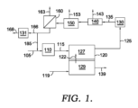
溶融炭酸塩型燃料電池の構造例
図3は、溶融炭酸塩型燃料電池の一般的な構成例を示す図である。図3に表される燃料電池は、燃料電池スタックの一部である燃料電池に相当する。燃料電池をスタック内の隣接する燃料電池から分離するために、燃料電池は、セパレータプレート310及び311を含む。図3において、燃料電池は、電解質342を含む電解質マトリックス340によって分離されているアノード330及びカソード350を含む。アノード集電体320は、アノード330とスタック内の他のアノードとの間の電気的接触を提供し、カソード集電体360は、カソード350と燃料電池スタック内の他のカソードとの間の同様の電気的接触を提供する。さらに、アノード集電体320は、アノード330からのガスの導入と排気を可能にし、カソード集電体360は、カソード350からのガスの導入と排気を可能にする。
Structural Example of Molten Carbonate Fuel Cell FIG. 3 is a diagram showing a general structural example of a molten carbonate fuel cell. The fuel cell represented in FIG. 3 corresponds to a fuel cell that is part of a fuel cell stack. The fuel cell includes
最初の電解質充填のために、固体電解質は、可能な限り、マトリックス、カソード、及びカソード集電体内部に組み込むことができる。初期充填の間は電解質が固体であるため、固体電解質をマトリックス及びカソードに添加するだけでは、所望の充填量を達成することが困難である場合がある。所望の充填を達成するために、カソード集電体にも固体電解質を添加してもよい。カソード集電体に添加した電解質は、燃料電池の作動に伴い溶融し、カソードに流れ込むことができる。同様に、カソードの電解質が溶融すると、溶融した電解質の一部がカソードからマトリックスに流れ込み、マトリックス体積の追加部分を満たすことができる。 For initial electrolyte filling, solid electrolytes can be incorporated within the matrix, cathode, and cathode current collector whenever possible. Because the electrolyte is solid during the initial filling, it may be difficult to achieve the desired loading by simply adding solid electrolyte to the matrix and cathode. A solid electrolyte may also be added to the cathode current collector to achieve the desired loading. The electrolyte added to the cathode current collector can melt and flow into the cathode as the fuel cell operates. Similarly, when the electrolyte at the cathode melts, some of the melted electrolyte can flow from the cathode into the matrix, filling an additional portion of the matrix volume.
実用的な考慮により、カソード集電体に添加される固体電解質の量も制限され得ることに留意されたい。固体電解質は時間とともに溶けるので、カソード集電体への固体電解質の充填量が多すぎると、カソード集電体を通ってカソードに到達するガスの能力が制限され得る。カソード集電体に非共晶組成を用いることで、ガス移動への影響を最小限に抑えつつ、カソード細孔容積の140体積%までの電解質の目標電解質充填を使用できることが発見された。しかしながら、電解質のさらなる添加は、望ましくない形でガス移動が制限される可能性がある。燃料電池の利用可能な表面積と比較して、これは、燃料電池面積250cm2当たり66グラム以下の電解質の目標充填に相当し得る。いくつかの態様において、目標充填は、燃料電池面積250cm2あたり40グラム~66グラムまたは45グラム~66グラム、または50グラム~66グラムの電解質とすることができる。目標電解質充填の一部は、カソード集電体に含まれることができることに留意されたい。カソード集電体に含まれる目標電解質充填の一部は、燃料電池面積250cm2あたり38グラム以下の電解質に対応し得る。いくつかの態様において、カソード集電体に含まれる目標電解質充填の一部は、燃料電池の面積250cm2あたり18グラム~38グラム、または24グラム~38グラム、または28グラム~38グラムの電解質に相当し得る。 Note that practical considerations may also limit the amount of solid electrolyte added to the cathode current collector. Because the solid electrolyte melts over time, too much solid electrolyte loading into the cathode current collector can limit the ability of gas to reach the cathode through the cathode current collector. It was discovered that by using a non-eutectic composition for the cathode current collector, a target electrolyte loading of up to 140% by volume of the cathode pore volume could be used while minimizing the impact on gas transfer. Further addition of electrolyte, however, can undesirably restrict gas transfer. Compared to the available surface area of the fuel cell, this may correspond to a target loading of electrolyte of 66 grams or less per 250 cm 2 of fuel cell area. In some embodiments, the target loading can be 40-66 grams, or 45-66 grams, or 50-66 grams of electrolyte per 250 cm 2 of fuel cell area. Note that part of the target electrolyte charge can be included in the cathode current collector. The portion of the target electrolyte loading contained in the cathode current collector may correspond to 38 grams or less of electrolyte per 250 cm 2 of fuel cell area. In some embodiments, the portion of the target electrolyte loading contained in the cathode current collector is from 18 grams to 38 grams, or from 24 grams to 38 grams, or from 28 grams to 38 grams of electrolyte per 250 cm area of the fuel cell. can be equivalent.
作動中、CO2はO2とともにカソード集電体360に通される。CO2及びO2は、多孔質カソード350に拡散し、カソード350と電解質マトリックス340との境界付近のカソード界面領域まで移動する。カソード界面領域では、電解質342の一部がカソード350の細孔に存在し得る。CO2及びO2は、カソード界面領域の近くで/内で炭酸イオン(CO3
2-)に変換され得、次いで、電解質342を横切って(したがって電解質マトリックス340を横切って)輸送されて電流の生成を促進することができる。代替イオン輸送が起こっている態様では、O2の一部は、電解質342中での輸送のために、水酸化物イオン又は過酸化物イオンなどの代替イオンに変換され得る。電解質342を横切って輸送された後、炭酸イオン(又は代替イオン)は、電解質マトリックス340とアノード330の境界付近のアノード界面領域に到達することができる。炭酸イオンは、H2の存在下でCO2とH2Oに戻され、燃料電池によって生成される電流を形成するために使用される電子を放出し得る。H2及び/又はH2を形成するのに適した炭化水素は、アノード集電体320を介してアノード330に導入される。
During operation, CO 2 is passed through cathode
溶融炭酸塩型燃料電池のアノード内のフロー方向は、カソード内のフロー方向に対して任意の都合の良い方向にすることができる。一つの選択肢は、アノード内のフロー方向がカソード内のフロー方向に対してほぼ90°の角度になるように、クロスフロー構成を使用することである。クロスフロー型にすることで、アノード入口・出口のマニホールドおよび/または配管を、カソード入口・出口のマニホールドおよび/または配管とは燃料電池スタックの異なる側に配置できるため、この種のフロー構成は実用上有利である。 The direction of flow within the anode of a molten carbonate fuel cell can be in any convenient direction relative to the direction of flow within the cathode. One option is to use a cross-flow configuration so that the direction of flow in the anode is at approximately a 90° angle to the direction of flow in the cathode. This type of flow configuration is practical because cross-flow allows the anode inlet/outlet manifolds and/or piping to be located on a different side of the fuel cell stack than the cathode inlet/outlet manifolds and/or piping. is advantageous.
溶融炭酸塩燃料の作動条件
炭素捕捉を行うために溶融炭酸塩型燃料電池を、任意選択で120mA/cm2以上の電流密度で、作動する場合、アノードの適切な条件には、アノードにH2、改質可能な燃料、またはそれらの組み合わせを供給すること、および20%~80%の範囲の燃料利用率を含む、所望の電流密度を生成する任意の都合のよい燃料利用率で作動することが含まれ得る。いくつかの態様では、これは、60%以上、または70%以上、例えば85%までの、または場合によってはさらに高い燃料利用率などの、従来の燃料利用量に対応することができる。他の態様では、これは、55%以下、または50%以下、または40%以下、例えば20%以下または場合によってはさらに低い燃料利用率など、高いH2含有量および/または高いH2およびCOの合計含有量(すなわち、合成ガス)を有するアノード出力ストリームを提供するために選択される燃料利用率に対応し得る。アノード出力ストリーム中のH2含有量および/またはアノード出力ストリーム中のH2およびCOの合計含有量は、所望の電流密度の生成を可能にするのに十分であることができる。いくつかの態様では、アノード出力ストリーム中のH2含有量は、3.0体積%以上、または5.0体積%以上、または8.0体積%以上、例えば最大15体積%または場合によってはさらに高くすることができる。追加または代替で、アノード出力ストリーム中のH2およびCOの合計量は、4.0体積%以上、または6.0体積%以上、または10体積%以上、例えば20体積%まで、またはさらに高い可能性がある。任意選択で、燃料電池が低燃料利用率で作動される場合、アノード出力ストリーム中のH2含有量は、10体積%~25体積%のH2含有量など、より高い範囲にすることができる。このような態様では、アノード出力ストリームの合成ガス含有量は、H2およびCO含有量の合計が15体積%~35体積%であるように、対応して高くすることができる。態様によっては、アノードは、生成される電気エネルギーの量を増やすために、生成される化学エネルギーの量を増やすために(すなわち、アノード出力ストリームで利用できる改質によって生成されるH2)、または代替イオン輸送を引き起こすために燃料電池を作動させることと互換性がある任意の他の便利な戦略を用いて作動させることができる。
Molten Carbonate Fuel Operating Conditions When operating a molten carbonate fuel cell to provide carbon capture, optionally at a current density of 120 mA/cm 2 or higher, suitable conditions for the anode include H 2 at the anode. , reformable fuel, or combinations thereof, and operating at any convenient fuel utilization that produces the desired current density, including fuel utilizations ranging from 20% to 80%. can be included. In some aspects, this may correspond to conventional fuel utilization, such as 60% or more, or 70% or more, eg, up to 85% or even higher fuel utilization. In other aspects, this means high H2 content and/or high H2 and CO, such as 55% or less, or 50% or less, or 40% or less, such as 20% or less, or even lower fuel utilization. may correspond to the fuel utilization selected to provide an anode output stream having a total content (ie syngas) of The H2 content in the anode output stream and/or the combined H2 and CO content in the anode output stream can be sufficient to allow production of the desired current density. In some aspects, the H2 content in the anode output stream is 3.0 vol% or more, or 5.0 vol% or more, or 8.0 vol% or more, such as up to 15 vol% or even can be raised. Additionally or alternatively, the total amount of H2 and CO in the anode output stream can be 4.0 vol.% or more, or 6.0 vol.% or more, or 10 vol.% or more, such as up to 20 vol.% or even higher. have a nature. Optionally, when the fuel cell is operated at low fuel utilization, the H2 content in the anode output stream can range higher, such as 10 vol% to 25 vol % H2 content. . In such embodiments, the synthesis gas content of the anode output stream can be correspondingly high such that the combined H 2 and CO content is between 15% and 35% by volume. In some embodiments, the anode is used to increase the amount of electrical energy produced, to increase the amount of chemical energy produced (i.e., H2 produced by reforming available in the anode output stream), or Any other convenient strategy compatible with operating a fuel cell to cause alternative ion transport can be used to operate.
様々な態様において、MCFCのためのアノード入力ストリームは、水素、メタンなどの炭化水素、CおよびHとは異なるヘテロ原子を含む得る炭化水素または炭化水素様化合物、またはそれらの組合せを含むことができる。水素/炭化水素/炭化水素様化合物の供給源は、燃料源と称することができる。いくつかの態様において、アノードに供給されるメタン(または他の炭化水素、炭化水素、または炭化水素様化合物)の大部分は、典型的には新鮮なメタンであり得る。本明細書において、新鮮なメタンのような新鮮な燃料とは、別の燃料電池プロセスからリサイクル(または再利用;recycle)されない燃料を指す。例えば、アノード出口ストリームからアノード入口にリサイクルされたメタンは、「新鮮な」メタンとはみなされず、代わりに再生されたメタンと表現することができる。 In various aspects, the anode input stream for the MCFC can comprise hydrogen, a hydrocarbon such as methane, a hydrocarbon or hydrocarbon-like compound that can contain heteroatoms different from C and H, or combinations thereof. . A source of hydrogen/hydrocarbon/hydrocarbon-like compounds can be referred to as a fuel source. In some embodiments, the majority of the methane (or other hydrocarbon, hydrocarbon, or hydrocarbon-like compounds) fed to the anode can typically be fresh methane. As used herein, fresh fuel, such as fresh methane, refers to fuel that has not been recycled from another fuel cell process. For example, methane recycled from the anode outlet stream to the anode inlet is not considered "fresh" methane and can instead be described as regenerated methane.
使用される燃料源は、カソード入力にCO2含有ストリームを提供するために燃料源の一部を使用するタービンなど、他の構成要素と共有することができる。燃料源の入力は、水素を生成する改質部において炭化水素(または炭化水素類似)化合物を改質するのに適した燃料に対する割合で水を含むことができる。例えば、メタンがH2を生成するために改質するための燃料入力である場合、燃料に対する水のモル比は、約1対1~約10対1、例えば少なくとも約2対1とすることができる。4対1以上の比率は外部改質で典型的であるが、より低い値は内部改質で典型的となり得る。H2が燃料源の一部である程度まで、アノードでのH2の酸化が燃料の改質に使用できるH2Oを生成する傾向があり得るので、いくつかの任意の態様では、燃料に追加の水は必要ない場合がある。燃料源はまた、任意に、燃料源に付随する成分を含むことができる(例えば、天然ガスフィードは、追加の成分としてCO2のある含有量を含むことができる)。例えば、天然ガスフィードは、CO2、N2、及び/又は他の不活性(希)ガスを追加的な成分として含むことができる。任意に、いくつかの態様において、燃料源はまた、アノード排気のリサイクルされた部分からのCO等の、COを含むことができる。燃料電池アセンブリへの燃料中のCOの追加または代替の潜在的供給源は、燃料電池アセンブリに入る前に燃料上で行われる炭化水素燃料の水蒸気改質によって生成されたCOであり得る。 The fuel source used can be shared with other components, such as a turbine that uses part of the fuel source to provide the CO2 - containing stream to the cathode input. The fuel source input may include water in proportion to fuel suitable for reforming hydrocarbon (or hydrocarbon-like) compounds in the reformer section to produce hydrogen. For example, if methane is the fuel input for reforming to produce H2, the molar ratio of water to fuel can be from about 1:1 to about 10:1, such as at least about 2 :1. can. Ratios of 4 to 1 or greater are typical for external reforming, but lower values can be typical for internal reforming. To the extent that H2 is part of the fuel source, since oxidation of H2 at the anode can tend to produce H2O that can be used to reform the fuel, in some optional of water may not be necessary. The fuel source can also optionally include components associated with the fuel source (eg, a natural gas feed can include some content of CO2 as an additional component). For example, natural gas feeds may include CO2 , N2 , and/or other inert (noble) gases as additional components. Optionally, in some embodiments, the fuel source can also contain CO, such as CO from a recycled portion of the anode exhaust. An additional or alternative potential source of CO in the fuel to the fuel cell assembly may be CO produced by steam reforming of a hydrocarbon fuel on the fuel prior to entering the fuel cell assembly.
より一般的には、様々な種類の燃料ストリームが、溶融炭酸塩型燃料電池のアノードのためのアノード入力ストリームとして使用するのに適している場合がある。いくつかの燃料ストリームは、C及びHとは異なるヘテロ原子も含み得る炭化水素及び/又は炭化水素様化合物を含むストリームに対応し得る。この議論において、特に指定しない限り、MCFCアノード用の炭化水素を含む燃料ストリームへの言及は、かかる炭化水素様化合物を含む燃料ストリームを含むと定義される。炭化水素(炭化水素様を含む)燃料ストリームの例には、天然ガス、C1~C4炭素化合物(メタン又はエタン等)を含むストリーム、及びより重いC5+炭化水素(炭化水素様化合物を含む)を含むストリーム、及びそれらの組み合わせが含まれる。アノード入力に使用するための潜在的な燃料ストリームのさらに他の追加または代替例としては、有機物の自然(生物)分解から生成されるメタンなどのバイオガスタイプのストリームを挙げることができる。 More generally, various types of fuel streams may be suitable for use as the anode input stream for the molten carbonate fuel cell anode. Some fuel streams may correspond to streams containing hydrocarbons and/or hydrocarbon-like compounds that may also contain heteroatoms different from C and H. In this discussion, unless otherwise specified, references to fuel streams containing hydrocarbons for MCFC anodes are defined to include fuel streams containing such hydrocarbon-like compounds. Examples of hydrocarbon (including hydrocarbon-like) fuel streams include natural gas, streams containing C1-C4 carbon compounds (such as methane or ethane), and heavier C5+ hydrocarbons (including hydrocarbon-like compounds). streams, and combinations thereof. Yet other additions or alternatives to potential fuel streams for use at the anode input include biogas type streams such as methane produced from the natural (bio)degradation of organic matter.
いくつかの態様において、溶融炭酸塩型燃料電池は、希釈剤化合物の存在によりエネルギー含有量が低い天然ガスおよび/または炭化水素ストリームなどの入力燃料ストリームを処理するために使用することができる。例えば、メタン及び/又は天然ガスのいくつかの供給源は、相当量のCO2又は窒素、アルゴン、若しくはヘリウムのような他の不活性分子のいずれかを含むことができる供給源である。高められた量のCO2および/または不活性成分の存在のために、供給源に基づく燃料ストリームのエネルギー含有量は減少し得る。エネルギー含有量の低い燃料を燃焼反応(燃焼式タービンの駆動など)に使用すると、困難が生じることがある。しかしながら、溶融炭酸塩型燃料電池は、燃料電池の効率への影響を低減または最小化しながら、低エネルギー含有量の燃料源に基づいて電力を生成することができる。ガス量が増えると、燃料の温度を改質および/またはアノード反応のための温度まで上昇させるために、追加の熱が必要になることがある。さらに、燃料電池アノード内の水ガスシフト反応の平衡の性質により、追加のCO2の存在は、アノード出力に存在するH2およびCOの相対量に影響を与える可能性がある。しかしながら、不活性化合物は、改質反応とアノード反応に直接影響を与えることはほとんどない。溶融炭酸塩型燃料電池の燃料ストリーム中のCO2および/または不活性化合物の量は、存在する場合、少なくとも約1体積%、例えば少なくとも約2体積%、または少なくとも約5体積%、または少なくとも約10体積%、または少なくとも約15体積%、または少なくとも約20体積%、または少なくとも約25体積%、または少なくとも約30体積%、または少なくとも約35体積%、または少なくとも約40体積%、または少なくとも45体積%、または少なくとも50体積%、または少なくとも約75体積%になり得る。さらに、または代替的に、溶融炭酸塩型燃料電池の燃料ストリーム中のCO2および/または不活性化合物の量は、約90体積%以下、例えば約75体積%以下、または約60体積%以下、または約50体積%以下、または約40体積%以下、または約35体積%以下とすることができる。 In some embodiments, molten carbonate fuel cells can be used to process input fuel streams such as natural gas and/or hydrocarbon streams that have low energy content due to the presence of diluent compounds. For example, some sources of methane and/or natural gas are sources that can contain either significant amounts of CO2 or other inert molecules such as nitrogen, argon, or helium. Due to the presence of increased amounts of CO2 and/or inert components, the energy content of the source-based fuel stream can be reduced. Difficulties can arise when low energy content fuels are used in combustion reactions (such as driving combustion turbines). However, molten carbonate fuel cells can generate power based on low energy content fuel sources while reducing or minimizing the impact on fuel cell efficiency. As the amount of gas increases, additional heat may be required to raise the temperature of the fuel to the temperature for reforming and/or anode reactions. Furthermore, due to the equilibrium nature of the water gas shift reaction within the fuel cell anode, the presence of additional CO2 can affect the relative amounts of H2 and CO present at the anode output . However, inert compounds rarely have a direct effect on the reforming and anode reactions. The amount of CO2 and/or inert compounds in the molten carbonate fuel cell fuel stream, if present, is at least about 1% by volume, such as at least about 2% by volume, or at least about 5% by volume, or at least about 10 vol.%, or at least about 15 vol.%, or at least about 20 vol.%, or at least about 25 vol.%, or at least about 30 vol.%, or at least about 35 vol.%, or at least about 40 vol.%, or at least 45 vol.% %, or at least 50% by volume, or at least about 75% by volume. Additionally or alternatively, the amount of CO2 and/or inert compounds in the fuel stream of the molten carbonate fuel cell is about 90 vol.% or less, such as about 75 vol.% or less, or about 60 vol.% or less; or about 50% by volume or less, or about 40% by volume or less, or about 35% by volume or less.
アノード入力ストリームの潜在的な供給源のさらに他の例は、精製所および/または他の工業プロセスの出力ストリームに対応することができる。例えば、コーキングは、多くの製油所において、より重い化合物をより低い沸点範囲に変換するための一般的なプロセスである。コーキングは通常、COおよび様々なC1~C4炭化水素など、室温で気体である様々な化合物を含むオフガスを生成する。このオフガスは、アノード投入ストリームの少なくとも一部として使用することができる。他の精製オフガスストリームは、追加的または代替的に、分解または他の精製プロセス中に生成されるライトエンド(C1~C4)など、アノード入力ストリームに含めるのに適していることがある。さらに他の適切な精製ストリームには、H2および/または改質可能な燃料化合物をも含むCOまたはCO2を含む精製ストリームを追加的または代替的に含めることができる。 Yet other examples of potential sources of anode input streams can correspond to output streams of refineries and/or other industrial processes. For example, coking is a common process in many refineries to convert heavier compounds to lower boiling ranges. Coking typically produces an off-gas containing various compounds that are gaseous at room temperature, such as CO and various C 1 -C 4 hydrocarbons. This off-gas can be used as at least part of the anode input stream. Other refinery off-gas streams may additionally or alternatively be suitable for inclusion in the anode input stream, such as light ends (C 1 -C 4 ) produced during cracking or other refinery processes. Still other suitable refinery streams may additionally or alternatively include CO or CO2 - containing refinery streams that also contain H2 and/or reformable fuel compounds.
アノード入力のためのさらに他の潜在的な供給源は、追加的にまたは代替的に、水含有量が増加したストリームを含むことができる。例えば、エタノールプラント(または別のタイプの発酵プロセス)からのエタノール出力ストリームは、最終蒸留の前にH2Oのかなりの部分を含むことができる。このようなH2Oは、典型的には、燃料電池の作動に最小限の影響しか与えないことができる。したがって、アルコール(または他の発酵生成物)と水との発酵混合物は、アノード入力ストリームの少なくとも一部として使用することができる。 Still other potential sources for anode input may additionally or alternatively include streams with increased water content. For example, an ethanol output stream from an ethanol plant (or another type of fermentation process) may contain a significant portion of H2O prior to final distillation. Such H 2 O can typically have minimal impact on fuel cell operation. Thus, a fermentation mixture of alcohol (or other fermentation product) and water can be used as at least part of the anode input stream.
バイオガス、または消化器ガスは、アノード入力のための別の追加的または代替的な潜在的供給源である。バイオガスは、主にメタン及びCO2から構成され、典型的には、有機物の分解又は消化によって生成される。嫌気性細菌は、有機物を消化し、バイオガスを生成するために使用されることがある。硫黄含有化合物などの不純物は、アノードとして使用する前にバイオガスから除去してもよい。 Biogas, or digestive gas, is another additional or alternative potential source for anode input. Biogas consists primarily of methane and CO2 and is typically produced by the decomposition or digestion of organic matter. Anaerobic bacteria are sometimes used to digest organic matter and produce biogas. Impurities such as sulfur-containing compounds may be removed from the biogas prior to use as an anode.
MCFCアノードからの出力ストリームは、H2O、CO2、CO、及びH2を含み得る。任意選択で、アノード出力ストリームは、追加の出力成分として、フィード中の未反応燃料(H2またはCH4など)または不活性化合物を有することもできる。この出力ストリームを改質反応に熱を供給するための燃料源として、またはセルを加熱するための燃焼燃料として使用する代わりに、1つ以上の分離をアノード出力ストリームに対して行い、H2またはCOなどの別のプロセスへの入力としての潜在的価値を有する成分からCO2を分離することが可能である。H2および/またはCOは、化学合成のための合成ガスとして、化学反応のための水素源として、および/または温室効果ガス排出を低減した燃料として使用することができる。 The output stream from the MCFC anode can contain H2O , CO2 , CO, and H2. Optionally, the anode output stream can also have unreacted fuel ( such as H2 or CH4 ) or inert compounds in the feed as additional output components. Instead of using this output stream as a fuel source to provide heat to the reforming reaction or as a combustion fuel to heat the cell, one or more separations are made to the anode output stream, H 2 or It is possible to separate CO2 from components that have potential value as input to another process such as CO. H2 and/or CO can be used as syngas for chemical synthesis, as a source of hydrogen for chemical reactions, and/or as a fuel with reduced greenhouse gas emissions.
アノード排気は、水-ガスシフトおよび成分の相互分離等、さまざまなガス処理オプションに付すができる。2つの一般的なアノード処理スキームを図1及び図2に示す。 The anode exhaust can be subjected to various gas treatment options such as water-gas shift and mutual separation of components. Two common anodization schemes are shown in FIGS. 1 and 2. FIG.
図1は、溶融炭酸塩型燃料電池アレイを化学合成プロセスと連動して作動させるための反応システムの一例を概略的に示している。図1において、燃料ストリーム105は、燃料電池アレイの燃料電池スタックの一部である燃料電池などの燃料電池120のアノード127に関連する改質段階(または複数の改質段階)110に提供される。燃料電池120に関連する改質段階(またはステージ、または段;stage))110は、燃料電池アセンブリの内部にあり得る。いくつかの任意の態様において、外部改質段階(図示せず)も、入力ストリームを燃料電池アセンブリに通す前に、入力ストリーム中の改質可能な燃料の一部を改質するために使用することができる。燃料ストリーム105は、メタン、他の炭化水素、及び/又は炭素-水素結合を含む有機化合物などの他の炭化水素様化合物などの改質可能な燃料を好ましくは含み得る。燃料ストリーム105は、任意選択でアノードリサイクルストリーム185によって提供されるH2及び/又はCOなど、H2及び/又はCOも任意選択で含み得る。アノードリサイクルストリーム185は任意であり、多くの態様において、燃料ストリーム105または改質燃料ストリーム115との組み合わせを介して直接的または間接的に、アノード排気125からアノード127に戻るリサイクルストリームが提供されないことに留意されたい。改質後、改質燃料ストリーム115は、燃料電池120のアノード127に通すことができる。CO2およびO2を含むストリーム119も、カソード129に通すことができる。燃料電池のカソード部分129からの炭酸イオン122、CO3
2-のフローは、アノード燃料電池反応に必要な残りの反応物を提供することができる。アノード127における反応に基づいて、得られるアノード排気125は、H2O、CO2、不完全に反応した燃料に対応する1つ以上の成分(H2、CO、CH4、又は改質可能燃料に対応する他の成分)、及び任意に燃料ストリーム105の一部であるN2及び/又は他の混入物質等の1つ以上の追加の非反応成分を含むことができる。次いで、アノード排気125は、1つ以上の分離段階に通され得る。例えば、CO2除去段階140は、低温CO2除去システム、CO2などの酸性ガスを除去するためのアミン洗浄段階、又はアノード排気からCO2出力ストリーム143を分離するための別の適切なタイプのCO2分離段階に対応することができる。任意選択的に、アノード排気は、最初に水ガスシフト反応器130を通過させて、アノード排気中に存在する任意のCOを(いくつかのH2Oと共に)任意選択的に水ガスシフトされたアノード排気135中のCO2とH2に変換することが可能である。CO2除去段階の性質に応じて、水凝縮または除去段階150が、アノード排気から水出力ストリーム153を除去するために望ましい場合がある。図1ではCO2分離段階140の後に示されているが、任意選択で、代わりにCO2分離段階140の前に配置されてもよい。さらに、H2の分離のためのオプションの膜分離段階160は、H2の高純度透過物ストリーム163を生成するために使用され得る。得られた残余分の(またはリテンテート、または保持物;retentate)ストリーム166は、その後、化学合成プロセスへの入力として使用され得る。ストリーム166は、H2、CO、およびCO2含有量を異なる比率に調整するために、第2の水-ガスシフト反応器131において追加的または代替的にシフトされ、化学合成プロセスにおけるさらなる使用のために出力ストリーム168を生成し得る。図1において、アノードリサイクルストリーム185は、残余分のストリーム166から取り出されるように示されているが、アノードリサイクルストリーム185は、追加的に又は代替的に、様々な分離段階の中又は間の他の都合の良い場所から取り出され得る。分離段階及びシフト反応器(複数可)は、追加的に又は代替的に、異なる順序で、及び/又は並列構成で構成され得る。最後に、CO2139の含有量が低減されたストリームが、カソード129からの出力として生成され得る。簡略化のために、プロセスにおいて有用である可能性のある圧縮及び熱の付加/除去の様々な段階、並びに蒸気の付加又は除去は、示されていない。
FIG. 1 schematically illustrates an example reaction system for operating a molten carbonate fuel cell array in conjunction with a chemical synthesis process. In FIG. 1, a
上述したように、アノード排気に対して行われる様々な種類の分離は、任意の便利な順序で行うことができる。図2は、アノード排気に対して分離を実行するための代替的な順序の一例を示す。図2において、アノード排気125は、アノード排気125から水素含有量の一部263を除去するための分離段階260に最初に通され得る。これは、例えば、H2対COの比が2:1に近い残余分266を提供するために、アノード排気のH2含有量を減少させることを可能にし得る。次いで、H2対COの比は、水ガスシフト段階230において所望の値を達成するようにさらに調整することができる。水ガスシフト出力235は、その後、CO2分離段階240及び水除去段階250を通過して、所望の化学合成プロセスへの入力としての使用に適した出力ストリーム275を生成することができる。任意選択で、出力ストリーム275は、追加の水ガスシフト段階(図示せず)に曝され得る。出力ストリーム275の一部は、任意選択で、アノード入力にリサイクルされ得る(図示せず)。もちろん、分離段階のさらに他の組み合わせ及び順序付けを使用して、所望の組成を有するアノード出力に基づくストリームを生成することができる。簡略化のために、プロセスにおいて有用である可能性のある圧縮および熱の付加/除去の様々な段階、ならびに蒸気の付加/除去は、示されていない。
As noted above, the various types of separation performed on the anode exhaust can be performed in any convenient order. FIG. 2 shows an example of an alternative sequence for performing separation on the anode exhaust. In FIG. 2,
カソードの入力と出力
炭素捕捉条件下で作動する場合、カソードの好適な条件は、CO2およびO2を含むカソード入力フローをカソードに提供することを含むことができる。炭素捕捉条件が代替イオン輸送が起こる条件に対応する態様では、カソード入力フローは、十分な量の水をさらに含むことができる。
Cathode Input and Output When operating under carbon capture conditions, suitable cathode conditions can include providing a cathode input flow comprising CO2 and O2 to the cathode. In embodiments where the carbon trapping conditions correspond to those under which alternative ion transport occurs, the cathode input flow can further include a sufficient amount of water.
カソード入力フロー中のCO2濃度は、10体積%以下、8.0体積%以下、6.0体積%以下、4.0体積%以下、例えば1.5体積%以下、またはさらに低い可能性がある。追加的にまたは代替的に、カソードは、60%以上、または70%以上、または80%以上、例えば95%まで、または場合によってはさらに高いCO2利用率で作動させることができる。CO2利用率が80%未満である場合、カソード入力フロー中のCO2濃度は10体積%以下とすることができることに留意されたい。いくつかの態様において、カソード入力ストリーム中のO2濃度は、4.0体積%~15体積%、または6.0体積%~10体積%の酸素含有量に対応することができる。 The CO2 concentration in the cathode input flow may be 10 vol.% or less, 8.0 vol.% or less, 6.0 vol.% or less, 4.0 vol.% or less, such as 1.5 vol.% or less, or even lower. be. Additionally or alternatively, the cathode may be operated at a CO2 utilization of 60% or more, or 70% or more, or 80% or more, such as up to 95%, or possibly even higher. Note that if the CO2 utilization is less than 80%, the CO2 concentration in the cathode input flow can be 10% by volume or less. In some embodiments, the O 2 concentration in the cathode input stream can correspond to an oxygen content of 4.0 vol.% to 15 vol.%, or 6.0 vol.% to 10 vol.%.
炭素捕捉条件が代替イオン輸送が起こる条件に対応する態様では、代替イオン輸送が起こるために十分な量の水も存在すべきことが観察されている。これは、カソード入力フロー中に1.0体積%以上、または2.0体積%以上の水が存在することに相当し得る。空気は一般的にO2源として使用され、H2Oは燃焼中に生成される生成物(CO2の一般的な供給源)の1つであるため、十分な量の水がカソード内で通常利用可能であることが留意される。 It has been observed that in embodiments where carbon trapping conditions correspond to those under which alternative ion transport occurs, a sufficient amount of water should also be present for alternative ion transport to occur. This may correspond to having 1.0 vol.% or more, or 2.0 vol.% or more water in the cathode input flow. Since air is commonly used as the O2 source and H2O is one of the products produced during combustion (a common source of CO2 ), a sufficient amount of water is Note that it is normally available.
従来、溶融炭酸塩型燃料電池は、アノードに供給される燃料ストリーム中の燃料の一部を消費しながら、所望の充填を引き出すことに基づいて作動させることができる。燃料電池の電圧は、充填、アノードへの燃料投入量、カソードに供給される空気とCO2、燃料電池の内部抵抗によって決定することができる。カソードに供給されるCO2は、従来、アノードの排気をカソード入力ストリームの少なくとも一部として使用することにより、その一部を供給することが可能であった。これに対して、本発明では、アノード入力とカソード入力に別々の/異なるソース(または源;source)を使用することができる。アノード入力フローの組成とカソード入力フローとの間のいかなる直接的な関連も取り除くことによって、過剰な合成ガスの生成、二酸化炭素の捕捉の改善、及び/又は燃料電池の総効率(電気+化学出力)の改善など、燃料電池の操作に追加の選択肢が利用可能となる。 Conventionally, molten carbonate fuel cells can be operated based on drawing a desired charge while consuming a portion of the fuel in the fuel stream supplied to the anode. The voltage of the fuel cell can be determined by the charge, the fuel input to the anode, the air and CO2 supplied to the cathode, and the internal resistance of the fuel cell. The CO2 supplied to the cathode could conventionally be supplied in part by using the anode exhaust as at least part of the cathode input stream. In contrast, the present invention allows the use of separate/different sources for the anode and cathode inputs. By removing any direct relationship between the composition of the anode input flow and the cathode input flow, excess synthesis gas production, improved carbon dioxide capture, and/or overall fuel cell efficiency (electrical + chemical output ), additional options become available for fuel cell operation.
カソード入力フローとして使用するための適切な二酸化炭素含有ストリームの一例は、燃焼源からの出力フロー又は排気フローであり得る。燃焼源の例としては、天然ガスの燃焼、石炭の燃焼、及び/又は他の炭化水素タイプの燃料(生物学的由来の燃料を含む)の燃焼に基づく源が挙げられるが、これらに限定されるものではない。追加または代替のソースは、他の物質(水または空気など)を加熱するために炭素含有燃料を燃焼させる他のタイプのボイラー、焼成ヒーター、炉、および/または他のタイプのデバイスを含むことができる。 An example of a suitable carbon dioxide-containing stream for use as a cathode input flow can be an output or exhaust flow from a combustion source. Examples of combustion sources include, but are not limited to, sources based on burning natural gas, burning coal, and/or burning other hydrocarbon-type fuels, including fuels of biological origin. not something. Additional or alternative sources may include other types of boilers, calcining heaters, furnaces, and/or other types of devices that burn carbon-containing fuels to heat other substances (such as water or air). can.
カソード入力ストリームの他の潜在的な供給源は、追加的または代替的に、生物学的に生成されたCO2の供給源を含むことができる。これは、例えば、エタノール生産中に発生するCO2など、バイオ由来化合物の処理中に発生するCO2を含むことができる。追加的または代替的な例としては、リグノセルロースの燃焼など、バイオ生成燃料の燃焼によって生成されるCO2を含むことができる。さらに他の追加的または代替的な潜在的CO2源は、鉄鋼、セメント、および/または紙の製造工場から発生するCO2含有ストリーム体など、様々な工業プロセスからの出力または排気ストリームに対応することができる。 Other potential sources of cathode input streams may additionally or alternatively include sources of biologically produced CO2 . This can include, for example, CO2 generated during processing of bio-derived compounds, such as CO2 generated during ethanol production. Additional or alternative examples can include CO2 produced by burning bio-generated fuels, such as burning lignocellulose. Yet other additional or alternative potential sources of CO2 correspond to output or exhaust streams from various industrial processes, such as CO2 - containing streams generated from steel, cement, and/or paper manufacturing plants. be able to.
さらに別の追加または代替の潜在的なCO2源は、燃料電池からのCO2含有ストリームとすることができる。燃料電池からのCO2含有ストリームは、別の燃料電池からのカソード出力ストリーム、別の燃料電池からのアノード出力ストリーム、カソード出力から燃料電池のカソード入力へのリサイクルストリーム、および/またはアノード出力から燃料電池のカソード入力へのリサイクルストリームに対応し得る。例えば、従来の条件下でスタンドアローンモードで作動されるMCFCは、少なくとも約5体積%のCO2濃度を有するカソード排気を発生させることができる。このようなCO2含有カソード排気は、本発明の一態様に従って作動するMCFCのカソード入力として使用され得る。より一般的には、カソード排気からCO2出力を生成する他のタイプの燃料電池を追加的または代替的に使用することができ、また、「燃焼」反応によっておよび/または燃焼式発電機によって生成されない他のタイプのCO2含有ストリームを使用することができる。任意選択であるが、好ましくは、別の燃料電池からのCO2含有ストリームは、別の溶融炭酸塩型燃料電池からのものであることができる。例えば、カソードに関して直列に接続された溶融炭酸塩型燃料電池の場合、第1の溶融炭酸塩型燃料電池用のカソードからの出力は、第2の溶融炭酸塩型燃料電池用のカソードへの入力として使用することが可能である。 Yet another additional or alternative potential source of CO2 can be a CO2 - containing stream from a fuel cell. A CO2 - containing stream from a fuel cell can be a cathode output stream from another fuel cell, an anode output stream from another fuel cell, a recycle stream from the cathode output to the cathode input of the fuel cell, and/or a fuel stream from the anode output. It may correspond to the recycle stream to the cathode input of the battery. For example, an MCFC operated in standalone mode under conventional conditions can produce a cathode exhaust with a CO2 concentration of at least about 5% by volume. Such CO2 - containing cathode exhaust can be used as the cathode input of an MCFC operating in accordance with one aspect of the present invention. More generally, other types of fuel cells that produce CO2 output from the cathode exhaust may additionally or alternatively be used, and may also be produced by a "combustion" reaction and/or by combustion generators. Other types of CO2 - containing streams that are not used can be used. Optionally, but preferably, the CO2 - containing stream from another fuel cell can be from another molten carbonate fuel cell. For example, with molten carbonate fuel cells connected in series with respect to their cathodes, the output from the cathode for the first molten carbonate fuel cell is the input to the cathode for the second molten carbonate fuel cell. can be used as
カソード反応に必要な成分を供給するために、CO2に加えてO2をカソード入力ストリームに含めることができる。いくつかのカソード入力ストリームは、空気を成分として有することに基づくことができる。例えば、燃焼排気ストリームは、空気の存在下で炭化水素燃料を燃焼させることによって形成することができる。このような燃焼排気ストリーム、または空気の含有に基づく酸素含有量を有する別のタイプのカソード入力ストリームは、約20体積%以下、例えば、約15体積%以下、または約10体積%以下の酸素含有量を有することができる。さらに、または代替的に、カソード入力ストリームの酸素含有量は、少なくとも約4体積%、例えば、少なくとも約6体積%、または少なくとも約8体積%とすることができる。より一般的には、カソード入力ストリームは、カソード反応の実行に適した酸素含有量を有することができる。いくつかの態様では、これは約5体積%~約15体積%、例えば約7体積%~約9体積%の酸素含有量に相当することができる。多くのタイプのカソード入力ストリームでは、CO2とO2の合計量は、入力ストリームの約21体積%未満、例えばストリームの約15体積%未満、またはストリームの約10体積%未満に対応することが可能である。酸素を含む空気ストリームは、酸素含有量の少ないCO2源と組み合わせることができる。例えば、石炭を燃焼させて生成された排気ストリームは、酸素含有量が低く、空気と混合してカソード入口ストリームを形成することが可能である。 In addition to CO2 , O2 can be included in the cathode input stream to provide the necessary components for the cathode reaction. Some cathode input streams can be based on having air as a component. For example, a combustion exhaust stream can be formed by burning a hydrocarbon fuel in the presence of air. Such a combustion exhaust stream, or another type of cathode input stream having an oxygen content based on air content, has an oxygen content of about 20 vol.% or less, such as about 15 vol.% or less, or about 10 vol.% or less. You can have quantity. Additionally or alternatively, the oxygen content of the cathode input stream can be at least about 4% by volume, such as at least about 6% by volume, or at least about 8% by volume. More generally, the cathode input stream can have an oxygen content suitable for carrying out the cathode reaction. In some embodiments, this can correspond to an oxygen content of about 5% to about 15%, such as about 7% to about 9% by volume. For many types of cathode input streams, the total amount of CO2 and O2 may correspond to less than about 21 vol.% of the input stream, such as less than about 15 vol.% of the stream, or less than about 10 vol.% of the stream. It is possible. An oxygen-containing air stream can be combined with an oxygen-poor CO2 source. For example, an exhaust stream produced by burning coal has a low oxygen content and can be mixed with air to form the cathode inlet stream.
CO2やO2の他に、N2、H2Oなどの不活性/非反応種、および他の典型的な酸化剤(空気)成分でカソード入力ストリームを構成することもできる。例えば、燃焼反応からの排気から得られるカソード入力の場合、燃焼反応のための酸化剤源の一部として空気が使用されるなら、排気ガスは、N2、H2O、および空気中に存在する微量の他の化合物などの空気の典型的な構成要素を含むことが可能である。燃焼反応のための燃料源の性質に応じて、燃料源に基づく燃焼後に存在する追加の種は、H2O、窒素酸化物(NOx)および/または硫黄(SOx)、ならびに燃料に存在するおよび/またはCOなどの燃料に存在する化合物の部分または完全燃焼生成物のいずれかである他の化合物の一つ以上を含んでもよい。これらの化合物は、カソード触媒の活性を低下させるが、カソード触媒表面を汚染しない程度の量で存在してもよい。このような性能低下は許容範囲内であるか、またはカソード触媒と相互作用する種は、既知の汚染物質除去技術によって許容レベルまで減少させることが可能である。 In addition to CO2 and O2 , inert/non-reactive species such as N2 , H2O , and other typical oxidant (air) components can also constitute the cathode input stream. For example, in the case of a cathode input obtained from exhaust from a combustion reaction, if air is used as part of the oxidant source for the combustion reaction, the exhaust gases will be present in N2 , H2O , and air. It can contain typical constituents of air such as trace amounts of other compounds that Depending on the nature of the fuel source for the combustion reaction, additional species present after combustion based on the fuel source are H 2 O, nitrogen oxides (NOx) and/or sulfur (SOx), and those present in the fuel and /or may include one or more other compounds that are either part of compounds present in the fuel, such as CO, or products of complete combustion. These compounds reduce the activity of the cathode catalyst, but may be present in amounts that do not contaminate the cathode catalyst surface. Such performance degradation is acceptable, or the species interacting with the cathode catalyst can be reduced to acceptable levels by known contaminant removal techniques.
カソード入力ストリーム(燃焼排気に基づく入力カソードストリームなど)中に存在するO2の量は、有利には、燃料電池におけるカソード反応に必要な酸素を提供するのに十分であることが可能である。したがって、O2の体積割合は、有利には、排気中のCO2の量の少なくとも0.5倍とすることができる。任意に、必要に応じて、カソード反応に十分な酸化剤を提供するために、カソード入力に追加の空気を添加することができる。ある種の空気が酸化剤として使用される場合、カソード排気中のN2の量は、少なくとも約78体積%、例えば、少なくとも約88体積%、および/または約95体積%以下とすることができる。いくつかの態様において、カソード入力ストリームは、H2SまたはNH3などの一般に汚染物質とみなされる化合物を追加的または代替に含むことができる。他の態様では、カソード入力ストリームは、そのような汚染物質の含有量を低減または最小化するために浄化することができる。 The amount of O2 present in the cathode input stream (such as an input cathode stream based on combustion exhaust) can advantageously be sufficient to provide the oxygen required for the cathode reaction in the fuel cell. Therefore, the volume fraction of O2 can advantageously be at least 0.5 times the amount of CO2 in the exhaust. Optionally, additional air can be added to the cathode input to provide sufficient oxidant for the cathode reaction, as needed. When some type of air is used as the oxidant, the amount of N2 in the cathode exhaust can be at least about 78 vol.%, such as at least about 88 vol.%, and/or no more than about 95 vol.% . In some embodiments, the cathode input stream can additionally or alternatively contain compounds commonly considered contaminants such as H2S or NH3 . In other aspects, the cathode input stream can be cleaned to reduce or minimize the content of such contaminants.
MCFCの作動に適した温度は、約450℃~約750℃、例えば少なくとも約500℃、例えば約550℃の入口温度と約625℃の出口温度であり得る。カソードに入る前に、必要に応じて、例えば、アノードのために入力された燃料を改質するなどの他のプロセスに熱を提供するために、カソード入力ストリームに熱を加えるかまたはカソード入力ストリームから熱を除去することが可能である。例えば、カソード入力ストリームのソースが燃焼排気ストリームである場合、燃焼排気ストリームは、カソード入口の所望の温度より高い温度を有し得る。このような場合、カソード入力ストリームとして使用する前に、燃焼排気から熱を除去することができる。あるいは、燃焼排気は、例えば石炭火力ボイラーの湿式ガススクラバー後のように非常に低い温度である可能性があり、この場合、燃焼排気は約100℃以下である可能性がある。あるいは、燃焼排気は、合計サイクルモードで作動されるガスタービンの排気である可能性もあり、この場合、ガスは、追加の発電のために蒸気タービンを作動するために蒸気を上げることによって冷却されることができる。この場合、ガスは約50℃未満であることが可能である。所望より低温の燃焼排気に熱を加えることができる。 Suitable temperatures for MCFC operation may be from about 450°C to about 750°C, such as at least about 500°C, such as an inlet temperature of about 550°C and an outlet temperature of about 625°C. Prior to entering the cathode, heat is added to or from the cathode input stream as needed to provide heat for other processes, such as reforming the fuel input for the anode. It is possible to remove heat from For example, if the source of the cathode input stream is the flue gas stream, the flue gas stream may have a higher temperature than the desired temperature of the cathode inlet. In such cases, heat can be removed from the flue gas prior to use as the cathode input stream. Alternatively, the flue gas may be at a very low temperature, such as after a wet gas scrubber in a coal-fired boiler, in which case the flue gas may be about 100° C. or less. Alternatively, the combustion exhaust could be the exhaust of a gas turbine operated in total cycle mode, where the gases are cooled by raising steam to operate the steam turbine for additional power generation. can In this case, the gas can be below about 50°C. Heat can be added to the cooler flue gas than desired.
追加の溶融炭酸塩型燃料電池の作動戦略
いくつかの態様では、代替イオン輸送を引き起こすためにMCFCを作動させる場合、燃料電池のアノードは、およそ60%から80%の従来の燃料利用値で作動させることができる。電力を生成しようとする場合、燃料電池のアノードを比較的高い燃料利用率で作動させると、電気効率(すなわち、燃料電池で消費される化学エネルギーの単位あたり生成される電気エネルギー)を向上させるのに有益である。
Additional Molten Carbonate Fuel Cell Operating Strategies In some embodiments, when operating MCFCs to induce alternate ion transport, the fuel cell anode operates at approximately 60% to 80% conventional fuel utilization values. can be made When power is to be produced, operating the anode of a fuel cell at relatively high fuel utilization can improve electrical efficiency (i.e., electrical energy produced per unit of chemical energy consumed by the fuel cell). beneficial to
いくつかの態様において、アノード出力フロー中に提供されるH2の量の増加などの他の利点を提供するために、燃料電池の電気効率を低下させることが有益である場合がある。これは、例えば、追加の改質を行うこと及び/又は別の吸熱反応を行うことによって、燃料電池(又は燃料電池スタック)において発生する過剰な熱を消費することが望ましい場合に、有益であり得る。例えば、溶融炭酸塩型燃料電池は、合成ガス及び/又は水素の生産量を増加させるように作動させることができる。吸熱改質反応に必要な熱は、発電のためのアノードにおける発熱性電気化学反応によって供給されることが可能である。発熱性燃料電池反応によって発生した熱を燃料電池から輸送しようとするのではなく、この余剰熱を改質反応及び/又は別の吸熱反応のための熱源としてその場で使用することができる。これにより、熱エネルギーをより効率的に利用することができ、外部または内部の熱交換を追加する必要性を低減することができる。熱エネルギーのこの効率的な生産と使用は、基本的に原位置で、有利な作動条件を維持しながら、システムの複雑さと構成要素を減らすことができる。いくつかの態様において、改質または他の吸熱反応の量は、従来技術において典型的に記載される熱要件よりも著しく小さいのではなく、発熱反応(複数可)によって生成される余剰熱の量に匹敵する、またはそれよりもさらに大きい吸熱要件を有するように選択することが可能である。 In some aspects, it may be beneficial to reduce the electrical efficiency of the fuel cell to provide other benefits such as increasing the amount of H2 provided in the anode output flow. This is beneficial when it is desired to dissipate the excess heat generated in the fuel cell (or fuel cell stack), for example by performing additional reforming and/or performing another endothermic reaction. obtain. For example, molten carbonate fuel cells can be operated to increase synthesis gas and/or hydrogen production. The heat required for the endothermic reforming reaction can be supplied by an exothermic electrochemical reaction at the anode for power generation. Rather than trying to transport the heat generated by the exothermic fuel cell reaction out of the fuel cell, this excess heat can be used in situ as a heat source for the reforming reaction and/or another endothermic reaction. This allows for more efficient utilization of thermal energy and reduces the need for additional external or internal heat exchange. This efficient production and use of thermal energy can reduce system complexity and components while maintaining favorable operating conditions, essentially in situ. In some embodiments, the amount of reforming or other endothermic reaction is not significantly less than the heat requirements typically described in the prior art, but rather the amount of excess heat generated by the exothermic reaction(s). can be chosen to have an endothermic requirement comparable to or even greater than
追加的にまたは代替的に、燃料電池は、アノード入口とアノード出口との間の温度差が正ではなく負になるように作動させることができる。したがって、アノード入口とアノード出口との間の温度上昇の代わりに、十分な量の改質および/または他の吸熱反応を行い、アノード出口からの出力ストリームをアノード入口温度よりも低温にすることができる。さらに追加的または代替的に、アノード入力とアノード出力との間の温度差が、電力を生成するための吸熱反応(複数可)とカソード燃焼反応およびアノード反応の合計発熱の相対的需要に基づく予想差よりも小さくなるように、燃料電池用ヒーターおよび/または内部改質段階(または他の内部吸熱反応段階)に追加の燃料を供給することができる。改質が吸熱反応として使用される態様では、余剰燃料を改質するために燃料電池を作動させると、熱交換および改質のためのシステムの複雑さを最小限に抑えながら、従来の燃料電池作動と比較して合成ガスの増加および/または水素の増加をもたらすことができる。追加の合成ガスおよび/または追加の水素は、その後、化学合成プロセスおよび/または「クリーン」燃料として使用するための水素の収集/再利用を含む様々な用途で使用することができる。 Additionally or alternatively, the fuel cell can be operated such that the temperature difference between the anode inlet and anode outlet is negative rather than positive. Therefore, instead of increasing the temperature between the anode inlet and the anode outlet, a sufficient amount of reforming and/or other endothermic reactions can occur to cool the output stream from the anode outlet below the anode inlet temperature. can. Additionally or alternatively, the temperature difference between the anode input and the anode output is predicted based on the relative demands of the endothermic reaction(s) and the total heat generation of the cathode combustion reaction and the anode reaction to produce electrical power. Additional fuel can be supplied to the fuel cell heater and/or internal reforming stage (or other internal endothermic reaction stage) to lessen the difference. In embodiments where reforming is used as an endothermic reaction, operating the fuel cell to reform the excess fuel reduces the complexity of the system for heat exchange and reforming while minimizing the complexity of the conventional fuel cell. An increase in syngas and/or an increase in hydrogen can be provided compared to operation. Additional syngas and/or additional hydrogen can then be used in a variety of applications, including chemical synthesis processes and/or hydrogen collection/reuse for use as a "clean" fuel.
アノードでの発熱反応によって酸化された水素1モルあたりに発生する熱量は、改質反応によって発生した水素1モルあたりに消費される熱量より実質的に大きくすることができる。溶融炭酸塩型燃料電池における水素の正味の反応(H2+1/2O2→H2O)は、水素分子の反応エンタルピーが約-285kJ/molとなることがある。このエネルギーの少なくとも一部は、燃料電池内で電気エネルギーに変換することができる。しかし、反応のエンタルピーと燃料電池によって生成される電気エネルギーとの差(約)は、燃料電池内で熱となり得る。このエネルギー量は、代わりに、セルの電流密度(単位面積当たりの電流)に、燃料電池の理論上の最大電圧と実際の電圧との差を乗じたもの、または<電流密度>*(Vmax-Vact)で表すことができる。このエネルギー量を、燃料電池の「廃熱」と定義している。改質の例として、メタンの改質エンタルピー(CH4+2H2O→4H2+CO2)は、メタンで約250kJ/mol、水素分子で約62kJ/molとすることができる。熱バランスの観点から、電気化学的に酸化された各水素分子は、改質によって1つ以上の水素分子を生成するのに十分な熱を発生させることができる。従来の構成では、この過剰な熱により、アノード入口からアノード出口までかなりの温度差が生じることがある。この余分な熱を燃料電池内の温度上昇に利用させるのではなく、それに見合った量の改質反応を行うことで余分な熱を消費させることができる。アノードで発生した余剰熱は、燃料電池内の燃焼反応によって発生した余剰熱で補うことができる。より一般的には、燃料電池のアノードで吸熱反応を行うこと、および/または燃料電池と一体化した吸熱反応段階で吸熱反応を行うことにより、余分な熱を消費することができる。 The amount of heat generated per mole of hydrogen oxidized by the exothermic reaction at the anode can be substantially greater than the amount of heat consumed per mole of hydrogen generated by the reforming reaction. The net reaction of hydrogen (H 2 +1/2O 2 →H 2 O) in a molten carbonate fuel cell can result in a reaction enthalpy of hydrogen molecules of about −285 kJ/mol. At least part of this energy can be converted into electrical energy in the fuel cell. However, the difference (approximately) between the enthalpy of reaction and the electrical energy produced by the fuel cell can result in heat within the fuel cell. This amount of energy is instead the current density of the cell (current per unit area) multiplied by the difference between the theoretical maximum voltage and the actual voltage of the fuel cell, or <current density>*(Vmax- Vact). This amount of energy is defined as the "waste heat" of the fuel cell. As an example of reforming, the reforming enthalpy of methane (CH 4 +2H 2 O→4H 2 +CO 2 ) can be about 250 kJ/mol for methane and about 62 kJ/mol for molecular hydrogen. From a heat balance point of view, each electrochemically oxidized hydrogen molecule can generate enough heat to produce one or more hydrogen molecules by reforming. In conventional configurations, this excess heat can result in significant temperature differentials from the anode inlet to the anode outlet. Instead of using this extra heat to raise the temperature inside the fuel cell, the excess heat can be consumed by carrying out a corresponding amount of reforming reaction. Excess heat generated at the anode can be supplemented with excess heat generated by the combustion reaction within the fuel cell. More generally, the extra heat can be dissipated by conducting an endothermic reaction at the anode of the fuel cell and/or by conducting an endothermic reaction in an endothermic reaction stage integrated with the fuel cell.
態様によっては、燃料電池の所望の熱比を達成するために、改質反応及び/又は他の吸熱反応の量を、アノードで反応した水素の量に対して選択することができる。本明細書で使用される場合、「熱比」は、燃料電池アセンブリ内の発熱反応(アノード及びカソードの両方における発熱反応を含む)によって生じる熱を、燃料電池アセンブリ内で生じる改質反応の吸熱要求量で除したものと定義される。数学的に表現すると、熱比(TH)=QEX/QENであり、QEXは発熱反応によって生じた熱の総和であり、QENは燃料電池内で生じる吸熱反応によって消費される熱の総和である。発熱反応によって生じる熱は、改質反応、水ガスシフト反応、カソードにおける燃焼反応(すなわち、燃料化合物の酸化)、及び/又はセル内の電気化学反応による任意の熱に対応し得ることに留意されたい。電気化学反応によって発生する熱は、電解質にわたる燃料電池反応の理想的な電気化学ポテンシャルから燃料電池の実際の出力電圧を引いたものに基づいて計算することができる。例えば、MCFCの反応の理想的な電気化学ポテンシャルは、セル内で起こる正味の反応に基づいて、約1.04Vであると考えられている。MCFCの作動中、セルは、様々な損失により、典型的には1.04V未満の出力電圧を有し得る。例えば、一般的な出力/作動電圧は約0.7Vとすることができる。発生する熱は、セルの電気化学的電位(すなわち、~1.04V)から作動電圧を引いたものに等しくすることができる。例えば、燃料電池で~0.7Vの出力電圧を達成するとき、セル内の電気化学反応によって生成される熱は~0.34Vとすることができる。したがって、このシナリオでは、電気化学反応によって、~0.7Vの電気と~0.34Vの熱エネルギーが生成されることになる。このような例では、~0.7Vの電気エネルギーはQEXに含まれない。言い換えれば、熱エネルギーは電気エネルギーではない。 In some embodiments, the amount of reforming and/or other endothermic reactions can be selected relative to the amount of hydrogen reacted at the anode to achieve the desired heat ratio of the fuel cell. As used herein, "heat ratio" refers to the heat produced by exothermic reactions (including exothermic reactions at both the anode and cathode) within the fuel cell assembly to the endothermic heat of the reforming reaction occurring within the fuel cell assembly. Defined as divided by demand. Expressed mathematically, the heat ratio (TH) = QEX/QEN, where QEX is the sum of the heat produced by the exothermic reactions and QEN is the amount of heat consumed by the endothermic reactions occurring within the fuel cell. summation. Note that the heat generated by exothermic reactions may correspond to any heat from reforming reactions, water gas shift reactions, combustion reactions at the cathode (i.e., oxidation of fuel compounds), and/or electrochemical reactions within the cell. . The heat generated by the electrochemical reaction can be calculated based on the ideal electrochemical potential of the fuel cell reaction across the electrolyte minus the actual output voltage of the fuel cell. For example, the ideal electrochemical potential for MCFC reactions is believed to be about 1.04 V, based on the net reactions occurring in the cell. During MCFC operation, the cell can typically have an output voltage of less than 1.04V due to various losses. For example, a typical output/operating voltage may be approximately 0.7V. The heat generated can be equal to the cell's electrochemical potential (ie, ˜1.04 V) minus the operating voltage. For example, when achieving an output voltage of ~0.7V in a fuel cell, the heat generated by the electrochemical reaction within the cell can be ~0.34V. Thus, in this scenario, the electrochemical reaction would produce ~0.7V of electricity and ~0.34V of thermal energy. In such an example, ~0.7V electrical energy is not included in Q EX . In other words, thermal energy is not electrical energy.
様々な態様において、熱比は、燃料電池スタック、燃料電池スタック内の個々の燃料電池、統合改質段階を有する燃料電池スタック、統合型吸熱反応段階を有する燃料電池スタック、またはそれらの組み合わせなどの任意の都合の良い燃料電池構造について決定することができる。熱比はまた、燃料電池のアセンブリ又は燃料電池スタックなどの燃料電池スタック内の異なる単位について計算されてもよい。例えば、熱比は、熱統合の観点から統合されるように燃料電池(または複数の燃料電池)に十分に近接した統合改質段階及び/又は統合型吸熱反応段階要素と共に燃料電池スタック内の燃料電池(または複数の燃料電池)に対して計算されてもよい。 In various aspects, the heat ratio can be a fuel cell stack, an individual fuel cell within a fuel cell stack, a fuel cell stack with an integrated reforming stage, a fuel cell stack with an integrated endothermic reaction stage, or combinations thereof. Any convenient fuel cell configuration can be determined. Thermal ratios may also be calculated for different units within a fuel cell stack, such as an assembly of fuel cells or a fuel cell stack. For example, the heat ratio may affect fuel in a fuel cell stack with integrated reforming stage and/or integrated endothermic reaction stage elements sufficiently close to the fuel cell (or fuel cells) to be integrated from a heat integration standpoint. It may be calculated for a battery (or multiple fuel cells).
熱統合の観点から、燃料電池スタックにおける特徴的な幅は、個々の燃料電池スタック要素の高さであることができる。別個の改質段階及び/又は別個の吸熱反応段階は、燃料電池とは異なるスタック内の高さを有し得ることに留意されたい。そのようなシナリオでは、燃料電池要素の高さを特徴的な高さとして使用することができる。この議論において、統合型吸熱反応段階は、統合型吸熱反応段階が改質のための熱源として燃料電池からの熱を使用できるように、1つ以上の燃料電池と統合された段階の熱と定義されることが可能である。このような統合型吸熱反応段階は、統合型段階に熱を供給する燃料電池からスタック要素の高さの10倍未満に配置されると定義することができる。例えば、統合型吸熱反応段階(改質段階など)は、熱統合された任意の燃料電池からスタック要素の高さの10倍未満、またはスタック要素の高さの8倍未満、またはスタック要素の高さの5倍未満、またはスタック要素の高さの3倍未満の位置に配置することが可能である。この議論において、燃料電池要素に隣接するスタック要素を表す統合改質段階及び/又は統合型吸熱反応段階は、隣接する燃料電池要素から約1スタック要素の高さ以下離れているものとして定義される。 From a thermal integration point of view, the characteristic width in the fuel cell stack can be the height of the individual fuel cell stack elements. Note that separate reforming stages and/or separate endothermic reaction stages may have different heights in the stack than the fuel cell. In such scenarios, the height of the fuel cell element can be used as the characteristic height. In this discussion, an integrated endothermic reaction stage is defined as the heat of a stage integrated with one or more fuel cells such that the integrated endothermic reaction stage can use heat from the fuel cells as a heat source for reforming. It is possible to be Such an integrated endothermic reaction stage can be defined as being located less than ten times the height of the stack elements from the fuel cell supplying heat to the integrated stage. For example, an integrated endothermic reaction stage (such as a reforming stage) may be less than 10 times the stack element height from any thermally integrated fuel cell, or less than 8 times the stack element height, or less than 8 times the stack element height. It is possible to place it at a position less than five times the height of the stack element, or less than three times the height of the stack element. In this discussion, an integrated reforming stage and/or an integrated endothermic reaction stage, representing a stack element adjacent to a fuel cell element, is defined as being no more than about one stack element height away from the adjacent fuel cell element. .
約1.3以下、または約1.15以下、または約1.0以下、または約0.95以下、または約0.90以下、または約0.85以下、または約0.80以下、または約0.75以下の熱比は、MCFC燃料電池の使用において通常求められる熱比より低くすることが可能である。本発明の態様において、熱比は、合成ガス生成、水素生成、吸熱反応を介した別の生成物の生成、またはそれらの組み合わせを増加および/または最適化するために低減させることができる。 about 1.3 or less, or about 1.15 or less, or about 1.0 or less, or about 0.95 or less, or about 0.90 or less, or about 0.85 or less, or about 0.80 or less, or about A heat ratio of 0.75 or less can be lower than that normally required in MCFC fuel cell applications. In aspects of the invention, the heat ratio can be decreased to increase and/or optimize synthesis gas production, hydrogen production, production of another product via an endothermic reaction, or a combination thereof.
本発明の様々な態様において、燃料電池の作動は、熱比に基づいて特徴付けることができる。燃料電池が所望の熱比を有するように作動される場合、溶融炭酸塩型燃料電池は、約1.5以下、例えば約1.3以下、または約1.15以下、または約1.0以下、または約0.95以下、または約0.90以下、または約0.85以下、または約0.80以下、または約0.75以下の熱比を有するよう作動されることができる。さらに、または代替的に、熱比は少なくとも約0.25、または少なくとも約0.35、または少なくとも約0.45、または少なくとも約0.50とすることができる。さらに追加的または代替的に、いくつかの態様において、燃料電池は、約40℃以下、例えば約20℃以下、または約10℃以下のアノード入力とアノード出力との間の温度上昇を有するように作動させることができる。さらに追加的または代替的に、燃料電池は、アノード入口の温度より約10℃低いから約10℃高いアノード出口温度を有するように作動させることができる。さらに追加的または代替的に、燃料電池は、少なくとも約5℃より大きい、または少なくとも約10℃より大きい、または少なくとも約20℃より大きい、または少なくとも約25℃より大きいなど、アノード入口温度がアノード出口温度より大きいように作動させることができる。さらに追加的にまたは代替的に、燃料電池は、アノード入口温度がアノード出口温度よりも約100℃以下、または約80℃以下、または約60℃以下、または約50℃以下、または約40℃以下、または約30℃以下、または約20℃以下大きいように作動させることができる。 In various aspects of the invention, fuel cell operation can be characterized based on heat ratios. When the fuel cell is operated to have the desired heat ratio, the molten carbonate fuel cell has a heat ratio of about 1.5 or less, such as about 1.3 or less, or about 1.15 or less, or about 1.0 or less. or less than or equal to about 0.95, or less than or equal to about 0.85, or less than or equal to about 0.80, or less than or equal to about 0.75. Additionally or alternatively, the thermal ratio can be at least about 0.25, or at least about 0.35, or at least about 0.45, or at least about 0.50. Additionally or alternatively, in some embodiments, the fuel cell has a temperature rise between anode input and anode output of about 40° C. or less, such as about 20° C. or less, or about 10° C. or less. can be activated. Additionally or alternatively, the fuel cell can be operated with an anode exit temperature that is about 10° C. lower to about 10° C. higher than the anode inlet temperature. Additionally or alternatively, the fuel cell has an anode inlet temperature of at least about 5°C, or at least about 10°C, or at least about 20°C, or at least about 25°C. It can be operated to be greater than temperature. Additionally or alternatively, the fuel cell has an anode inlet temperature of about 100° C. or less, or about 80° C. or less, or about 60° C. or less, or about 50° C. or less, or about 40° C. or less, than the anode exit temperature. , or about 30° C. or less, or about 20° C. or less.
熱比が1未満である燃料電池を作動すると、燃料電池全体の温度低下を引き起こす可能性がある。いくつかの態様において、アノード入口からアノード出口への温度低下が約100℃以下、例えば約80℃以下、又は約60℃以下、又は約50℃以下、又は約40℃以下、又は約30℃以下、又は約20℃以下となり得るように、改質及び/又は他の吸熱反応の量を制限することも可能である。アノード入口からアノード出口までの温度低下を制限することは、例えば、アノードにおける(改質による)燃料の完全または実質的に完全な変換を可能にするために十分な温度を維持するために有益であり得る。他の態様では、吸熱反応によって消費される熱と燃料電池に供給される追加の外部熱とのバランスにより、アノード入口温度がアノード出口温度よりも約100℃以下、例えば約80℃以下、約60℃以下、約50℃以下、約40℃以下、約30℃以下、約20℃以下だけ大きくなるように(熱交換または追加燃料の燃焼などにより)追加の熱が燃料電池に供給され得る。 Operating a fuel cell with a heat ratio of less than 1 can cause a temperature drop across the fuel cell. In some embodiments, the temperature drop from the anode inlet to the anode outlet is about 100° C. or less, such as about 80° C. or less, or about 60° C. or less, or about 50° C. or less, or about 40° C. or less, or about 30° C. or less. , or to limit the amount of reforming and/or other endothermic reactions so that it can be about 20° C. or less. Limiting the temperature drop from the anode inlet to the anode outlet is beneficial, for example, to maintain a sufficient temperature to allow complete or substantially complete conversion of the fuel (by reforming) at the anode. possible. In other embodiments, the balance between the heat consumed by the endothermic reaction and the additional external heat supplied to the fuel cell causes the anode inlet temperature to be about 100° C. or lower, such as about 80° C. or lower, about 60° C. or lower than the anode outlet temperature. C. or less, about 50.degree. C. or less, about 40.degree. C. or less, about 30.degree. C. or less, about 20.degree.
改質量は、追加的または代替的に、改質可能な燃料の利用可能性に依存することができる。例えば、燃料がH2のみを含む場合、H2は既に改質されており、それ以上改質できないため、改質は行われない。燃料電池によって生成される「合成ガス」の量は、アノード入力における合成ガスの低位発熱量(LHV)値対アノード出力における合成ガスのLVH値の差として定義することができる。
合成ガス(sg)生産量LHV(sg net)=(LHV(sg out)-LHV(sg in))
ここで、LHV(sg in)およびLHV(sg out)は、それぞれ、アノード入口ストリームまたはフローにおける合成ガスおよびアノード出口ストリームまたはフローにおける合成ガスのLHVを指す。H2を相当量含む燃料を備える燃料電池は、追加の改質可能な燃料を含むのとは対照的に、燃料が既に改質されたH2を相当量含むので、潜在的な合成ガスの生成量を制限することができる。より低い(または低位;lower)熱量は、気相の完全酸化生成物(すなわち、気相のCO2およびH2O生成物)に対する燃料成分の燃焼のエンタルピーとして定義される。例えば、アノード入力ストリームに存在するCO2は、CO2が既に完全に酸化されているため、アノード入力の燃料含有量に寄与しない。この定義では、アノード燃料電池反応によりアノードで生じる酸化の量は、アノードにおける電気化学反応の一部としてアノードにおけるH2の酸化と定義される。
The amount of reformation may additionally or alternatively depend on the availability of reformable fuels. For example, if the fuel contains only H2, no reforming takes place because H2 has already been reformed and cannot be reformed further. The amount of "syngas" produced by a fuel cell can be defined as the difference between the lower heating value (LHV) value of the syngas at the anode input versus the LVH value of the syngas at the anode output.
Syngas (sg) production LHV (sg net) = (LHV (sg out) - LHV (sg in))
Here, LHV(sg in) and LHV(sg out) refer to the LHV of syngas in the anode inlet stream or flow and syngas in the anode outlet stream or flow, respectively. A fuel cell with a fuel containing a significant amount of H2 has a potential for syngas because the fuel already contains a substantial amount of reformed H2 , as opposed to containing additional reformable fuel. You can limit the amount produced. The lower (or lower) calorific value is defined as the enthalpy of combustion of the fuel component relative to the gas phase complete oxidation products (ie, the gas phase CO 2 and H 2 O products). For example, the CO2 present in the anode input stream does not contribute to the anode input fuel content because the CO2 is already fully oxidized. In this definition, the amount of oxidation that occurs at the anode due to the anode fuel cell reaction is defined as the oxidation of H2 at the anode as part of the electrochemical reaction at the anode.
燃料電池を熱比を低下させて作動する方法の例としては、燃料電池における熱の発生と消費のバランスをとるため、および/または発生した熱よりも多く消費するために、燃料の過剰改質を行う方法を挙げることができる。改質可能な燃料を改質してH2及び/又はCOを形成することは吸熱プロセスであり得るが、アノード電気化学酸化反応及びカソード燃焼反応(複数可)は発熱性であり得る。従来の燃料電池作動中、燃料電池作動用の供給成分を供給するために必要な改質量は、通常、アノード酸化反応によって発生する熱量よりも少ない熱量を消費することができる。例えば、約70%又は約75%の燃料利用率での従来の作動は、少なくとも約1.4以上、又は1.5以上の熱比など、実質的に1より大きい熱比を生じさせる。その結果、燃料電池の出力ストリームは、入力ストリームよりも高温になる可能性がある。このような従来の作動の代わりに、アノードに関連する改質段階で改質される燃料の量を増加させることができる。例えば、発熱性燃料電池反応によって生成される熱が改質において消費される熱と(ほぼ)釣り合うように、及び/又は生成される熱よりも多くの熱を消費するように、追加の燃料を改質することが可能である。これにより、発電用アノードで酸化される量に対して水素が大幅に過剰となり、約1.0以下、例えば約0.95以下、約0.90以下、約0.85以下、約0.80以下、約0.75以下の熱比となることが可能である。 Examples of methods of operating a fuel cell at a reduced heat ratio include over-reforming the fuel to balance heat production and consumption in the fuel cell and/or to consume more heat than is produced. can be mentioned. Reforming a reformable fuel to form H2 and/or CO may be an endothermic process, whereas the anodic electrochemical oxidation reaction and cathodic combustion reaction(s) may be exothermic. During conventional fuel cell operation, the amount of reformation required to supply the feed components for fuel cell operation can typically consume less heat than is generated by the anodization reaction. For example, conventional operation at about 70% or about 75% fuel utilization yields heat ratios substantially greater than 1, such as heat ratios of at least about 1.4 or greater, or 1.5 or greater. As a result, the fuel cell output stream can be hotter than the input stream. As an alternative to such conventional operation, the amount of fuel reformed in the reforming stage associated with the anode can be increased. For example, adding additional fuel so that the heat produced by the exothermic fuel cell reaction (approximately) matches the heat consumed in reforming and/or consumes more heat than is produced. It can be modified. This results in a significant excess of hydrogen relative to the amount oxidized at the power generating anode, about 1.0 or less, such as about 0.95 or less, about 0.90 or less, about 0.85 or less, about 0.80 Below, it is possible to have a thermal ratio of about 0.75 or less.
アノード排気からは、化学エネルギー出力として、水素または合成ガスのいずれかを取り出すことができる。水素は、燃えた時または燃焼時に温室効果ガスを発生させないクリーンな燃料として利用することができる。代わりに、炭化水素(または炭化水素系化合物)の改質によって生成された水素の場合、CO2はすでにアノードループで「捕捉」されている。さらに、水素は、様々な精製プロセスおよび/または他の合成プロセスへの貴重な投入物となり得る。合成ガスもまた、さまざまなプロセスにとって価値ある投入物となり得る。燃料としての価値に加えて、合成ガスは、フィッシャー・トロプシュ合成および/またはメタノール合成プロセスの入力として合成ガスを使用するなど、他の高価値製品を製造するための原料として使用することができる。 Either hydrogen or syngas can be taken from the anode exhaust as chemical energy output. Hydrogen can be used as a clean fuel that does not produce greenhouse gases when burned or combusted. Instead, for hydrogen produced by reforming of hydrocarbons (or hydrocarbonaceous compounds), CO2 is already "captured" in the anode loop. Additionally, hydrogen can be a valuable input to various refining and/or other synthetic processes. Syngas can also be a valuable input to various processes. In addition to its value as a fuel, syngas can be used as a feedstock to make other high value products, such as using syngas as an input for Fischer-Tropsch synthesis and/or methanol synthesis processes.
いくつかの態様において、アノードに送られる、および/またはアノードに関連する改質段階に送られる入力ストリーム中の改質可能燃料の改質可能水素含有量は、アノードで反応した水素の正味量よりも少なくとも約50%大きく、例えば少なくとも約75%または少なくとも約100%大きくすることができる。追加的にまたは代替的に、アノードおよび/またはアノードに関連する改質段階に送られる入力ストリーム中の燃料の改質可能な水素含有量は、アノードで反応した水素の正味量よりも少なくとも約50%大きく、例えば、少なくとも約75%または少なくとも約100%大きいことが可能である。様々な態様において、アノードで反応した水素の量に対する燃料ストリーム中の改質可能な燃料の改質可能な水素含有量の比は、少なくとも約1.5:1、または少なくとも約2.0:1、または少なくとも約2.5:1、または少なくとも約3.0:1であることができる。追加的にまたは代替的に、アノードで反応した水素量に対する燃料ストリーム中の改質可能な燃料の改質可能な水素量の比は、約20:1以下、例えば約15:1以下または約10:1以下とすることができる。一態様では、アノード入口ストリーム中の改質可能な水素含有量の100%未満が水素に変換され得ることが企図される。例えば、アノード入口ストリーム中の改質可能な水素含有量の少なくとも約80%は、アノードおよび/または関連する改質段階(複数可)で水素に変換することができ、例えば、少なくとも約85%、または少なくとも約90%である。追加的にまたは代替的に、アノードに供給される改質可能な燃料の量は、アノードで酸化された水素のLHVに対する改質可能な燃料の低位発熱量(LHV)に基づいて特徴付けられることが可能である。これは、改質可能な燃料の余剰比率と呼ばれ得る。様々な態様において、改質可能な燃料の余剰比は、少なくとも約2.0、例えば少なくとも約2.5、または少なくとも約3.0、または少なくとも約4.0とすることができる。さらに、または代替的に、改質可能な燃料の余剰比は、約25.0以下、例えば約20.0以下、または約15.0以下、または約10.0以下とすることができる。 In some embodiments, the reformable hydrogen content of the reformable fuel in the input stream sent to the anode and/or sent to a reforming stage associated with the anode is greater than the net amount of hydrogen reacted at the anode. can also be at least about 50% greater, such as at least about 75% greater or at least about 100% greater. Additionally or alternatively, the reformable hydrogen content of the fuel in the input stream sent to the anode and/or the reforming stage associated with the anode is at least about 50% greater than the net amount of hydrogen reacted at the anode. % greater, such as at least about 75% greater or at least about 100% greater. In various aspects, the ratio of the reformable hydrogen content of the reformable fuel in the fuel stream to the amount of hydrogen reacted at the anode is at least about 1.5:1, or at least about 2.0:1. , or at least about 2.5:1, or at least about 3.0:1. Additionally or alternatively, the ratio of the amount of reformable hydrogen in the reformable fuel in the fuel stream to the amount of hydrogen reacted at the anode is about 20:1 or less, such as about 15:1 or less or about 10 : 1 or less. In one aspect, it is contemplated that less than 100% of the reformable hydrogen content in the anode inlet stream can be converted to hydrogen. For example, at least about 80% of the reformable hydrogen content in the anode inlet stream can be converted to hydrogen at the anode and/or associated reforming stage(s), e.g., at least about 85%, or at least about 90%. Additionally or alternatively, the amount of reformable fuel supplied to the anode is characterized based on the lower heating value (LHV) of the reformable fuel relative to the LHV of hydrogen oxidized at the anode. is possible. This may be referred to as the reformable fuel surplus ratio. In various aspects, the reformable fuel surplus ratio can be at least about 2.0, such as at least about 2.5, or at least about 3.0, or at least about 4.0. Additionally or alternatively, the reformable fuel surplus ratio may be about 25.0 or less, such as about 20.0 or less, or about 15.0 or less, or about 10.0 or less.
実施例
様々な態様において、燃料電池のために高められた目標電解質充填レベルを使用することは、標準的な目標充填レベルを使用することと比較して、作動電圧の予期せぬ上昇及び作動寿命の利点を提供することができる。
EXAMPLES In various aspects, using an elevated target electrolyte fill level for a fuel cell results in an unexpected rise in operating voltage and operating life compared to using a standard target fill level. can provide the benefits of
作動電圧の予期せぬ増加は、標準条件下での溶融炭酸塩型燃料電池の電圧挙動との比較で説明することができる。表1は、さまざまな条件で作動された燃料電池の作動開始時の電圧値を示している。燃料電池の大きさは250cm2であった。燃料電池の目標電解質充填レベルは、カソード細孔容積の56体積%またはカソード細孔容積の80体積%のいずれかに相当する。カソード電解質の目標充填レベル80体積%は、合計目標電解質充填レベル約87体積%に対応することに留意されたい。作動条件は、従来の条件(カソード入力フローに17体積%のCO2、75%のCO2利用率)または炭素捕捉条件(カソード入力フローに4体積%のCO2、90%のCO2利用率)に相当する。 The unexpected increase in operating voltage can be explained by comparison with the voltage behavior of molten carbonate fuel cells under standard conditions. Table 1 shows voltage values at start-up for fuel cells operated under various conditions. The size of the fuel cell was 250 cm 2 . The target electrolyte filling level for the fuel cell corresponds to either 56% by volume of the cathode pore volume or 80% by volume of the cathode pore volume. Note that the target cathode electrolyte fill level of 80 vol.% corresponds to a total target electrolyte fill level of about 87 vol.%. Operating conditions were either conventional conditions (17 vol.% CO2 on the cathode input flow, 75% CO2 utilization) or carbon capture conditions (4 vol.% CO2 on the cathode input flow, 90% CO2 utilization). ).

表1に示すように、従来条件では、目標カソード電解質充填レベルをカソード細孔容積の80体積%に増加させると、作動開始時の作動電圧が10mVを超えて低下する。炭素捕捉条件では、従来の目標電解質充填量と高められた電解質充填量との間の電圧差は小さくなるが、炭素捕捉条件での燃料電池の作動開始時の作動電圧は、従来の目標電解質充填量の方が依然高い。表1より、標準的な作動条件では、カソード細孔容積の50体積%~60体積%の標準的な目標電解質充填レベルで作動することに明らかな利点があることがわかる。このことは、従来の溶融炭酸塩型燃料電池の理解では、標準的な目標充填レベルを使用することに落ち着いていた理由を示している。また、炭素捕捉条件であっても、寿命開始時の作動電圧のみを考慮すれば、標準的な目標充填レベルで作動することが有利であるように思われる。 As shown in Table 1, under conventional conditions, increasing the target cathode electrolyte filling level to 80% by volume of the cathode pore volume reduces the actuation voltage at start-up by more than 10 mV. Under carbon trapping conditions, the voltage difference between the conventional target electrolyte loading and the elevated electrolyte loading is small, but the operating voltage at the start of operation of the fuel cell under carbon trapping conditions is approximately equal to that of the conventional target electrolyte loading. quantity is still higher. From Table 1, it can be seen that under standard operating conditions there is a clear advantage to operating at standard target electrolyte loading levels of 50% to 60% by volume of the cathode pore volume. This explains why the conventional understanding of molten carbonate fuel cells has been limited to using standard target fill levels. Also, even with carbon capture conditions, it appears advantageous to operate at standard target fill levels if only the start of life operating voltage is considered.
表1とは対照的に、図4は、ある期間にわたって炭素捕捉条件で作動された溶融炭酸塩型燃料電池の電圧挙動を示す。図4に示すデータを作成するために、溶融炭酸塩型燃料電池は、4.0体積%~5.0体積%のCO2を含むカソード入力フローで、120mA/cm2または150mA/cm2のいずれかの電流密度を生成し、CO2利用率が約90%となるように作動された。燃料電池は、標準的な目標電解質充填レベル(カソード細孔容積の50体積%~56体積%、合計目標電解質充填レベルは約63体積%~70体積%)または高められた目標電解質充填レベル(カソード細孔容積の80体積%以上、合計目標電解質充填レベルは約87体積%)を有していた。 In contrast to Table 1, Figure 4 shows the voltage behavior of a molten carbonate fuel cell operated in carbon capture conditions over a period of time. To generate the data shown in FIG. 4, the molten carbonate fuel cell was operated at either 120 mA/cm 2 or 150 mA/cm 2 with a cathode input flow containing 4.0 vol % to 5.0 vol % CO 2 . Either current density was produced and operated at a CO2 utilization of approximately 90%. The fuel cell has a standard target electrolyte filling level (50% to 56% by volume of the cathode pore volume, with a total target electrolyte filling level of about 63% to 70% by volume) or an elevated target electrolyte filling level (cathode 80% by volume of the pore volume, with a total target electrolyte loading level of about 87% by volume).
図4に示すように、初期の短い期間の後、高められた目標電解質充填レベルを有する燃料電池の作動電圧は、標準的な目標電解質充填レベルを有する燃料電池の作動電圧より高かった。(120mA/cm2の標準的な目標充填レベルに対する最初の数時間のデータ点群は図4に示されていないが、寿命の始まりの電圧は対応する高められた目標充填レベルより短時間高かったと考えられる)。このことは、時間の経過とともに、より高い目標充填レベルの電解質で作動することにより、予期しない作動電圧の上昇がもたらされたことを示している。この予期せぬ作動電圧の上昇は、150mA/cm2という高い電流密度でより顕著になった。 As shown in FIG. 4, after an initial short period, the operating voltage of the fuel cell with the increased target electrolyte filling level was higher than that of the fuel cell with the standard target electrolyte filling level. (Data points for the first few hours for the standard target fill level of 120 mA/cm 2 are not shown in FIG. 4, but it is assumed that the voltage at the beginning of life was briefly higher than the corresponding elevated target fill level. Conceivable). This indicates that over time, operating with higher target fill levels of electrolyte resulted in an unexpected increase in operating voltage. This unexpected increase in actuation voltage became more pronounced at current densities as high as 150 mA/cm 2 .
炭素捕捉条件下で高められた目標電解質充填レベルを使用したときに作動電圧が向上したのは、燃料電池内のリチウムの損失が増加したことが一因であると考えられる。リチウムの損失の増大は、いくつかの方法で観察することができる。リチウムの損失増加の1つの指標は、炭素捕捉条件での長期作動後に溶融炭酸塩型燃料電池に存在する電解質の量が全体的に減少していることである。 It is believed that the increased loss of lithium in the fuel cell contributed in part to the improved operating voltage when using increased target electrolyte loading levels under carbon capture conditions. Increased loss of lithium can be observed in several ways. One indication of the increased loss of lithium is the overall decrease in the amount of electrolyte present in molten carbonate fuel cells after long term operation at carbon capture conditions.
表2は、溶融炭酸塩型燃料電池を炭素捕捉条件(カソード入力ストリーム中のCO2が~4.0体積%、CO2利用率が~90%)で2500時間作動した後の、溶融炭酸塩型燃料電池の様々な部分の電解質の相対充填レベルを示している。目標電解質充填レベルは、カソード細孔容積の約56体積%、マトリックス容積の90体積%以上という標準的な充填レベルであった。これは、約70体積%の合計目標電解質充填レベルに相当する。表2に示す結果は,従来の条件で2500時間作動した燃料電池のベースラインとの比較である.充填レベルの変化は、燃料電池の各部分で利用可能な細孔容積に基づいている。 Table 2 presents the molten carbonate yield after operating the molten carbonate fuel cell at carbon capture conditions (~4.0 vol.% CO2 in the cathode input stream, ~90% CO2 utilization) for 2500 hours. 4 shows the relative filling levels of electrolyte in various parts of a fuel cell model. The target electrolyte filling level was a typical filling level of about 56 vol % of the cathode pore volume and 90 vol % or more of the matrix volume. This corresponds to a total target electrolyte loading level of about 70% by volume. The results shown in Table 2 are compared with the baseline of fuel cells operated for 2500 hours under conventional conditions. The change in fill level is based on the pore volume available in each portion of the fuel cell.

リチウムの損失が増加したのは、カソード自体へのリチウムの取り込みが増加したことが一因であると考えられる。このカソードへのリチウムの取り込みの増加について、図5を用いて説明する。図5は、様々な条件下でリチウムに試験環境中で暴露した後のカソード構造物の誘導結合プラズマ質量分析(ICP-MS)を示す図である。カソード構造体は、酸化ニッケルから構成されていた。カソード構造物は、カソード構造物、電解質、カソード集電体をセル外試験装置で酸化環境を模擬した環境に暴露して試験された。酸化環境は数種類用意した。第1の酸化環境は、0.5体積%のCO2、9体積%のO2、および10体積%のH2Oに相当し、残りはN2である。第2の酸化環境は、4.1体積%のCO2、9体積%のO2、および10体積%のH2Oに対応し、残りはN2である。第3の酸化環境は、18.5体積%のCO2、11.3体積%のO2、および3.0体積%のH2Oに対応し、残りはN2である。第3の酸化環境は従来の溶融炭酸塩型燃料電池の条件に対応し、第1および第2の酸化環境は炭素捕捉条件に対応することに留意されたい。 The increased lithium loss is believed to be due in part to increased lithium incorporation into the cathode itself. This increase in incorporation of lithium into the cathode will be described with reference to FIG. FIG. 5 shows inductively coupled plasma-mass spectroscopy (ICP-MS) of cathode structures after exposure in a test environment to lithium under various conditions. The cathode structure was composed of nickel oxide. The cathode construction was tested by exposing the cathode construction, electrolyte, and cathode current collector to an environment simulating an oxidizing environment in an out-of-cell test fixture. Several types of oxidizing environments were prepared. The first oxidizing environment corresponds to 0.5 vol.% CO 2 , 9 vol.% O 2 , and 10 vol.% H 2 O, the remainder being N 2 . The second oxidizing environment corresponds to 4.1 vol.% CO2 , 9 vol.% O2 , and 10 vol.% H2O , with the balance being N2 . The third oxidizing environment corresponds to 18.5 vol.% CO2 , 11.3 vol.% O2 , and 3.0 vol.% H2O , with the balance being N2 . Note that the third oxidizing environment corresponds to conventional molten carbonate fuel cell conditions, and the first and second oxidizing environments correspond to carbon capture conditions.
セル外試験装置内のモデル燃料電池構造体を様々な酸化環境に暴露した後、ICP-MSを用いてカソードの組成を分析し、リチウム含有量を決定した。図5に示すように、燃料電池を従来の作動条件に曝すと、リチウム含有量が3.0質量%未満のカソードが得られた。一方、燃料電池を約4.0体積%のCO2を含む酸化環境に曝したところ、カソードのリチウム含有量は4.0質量%を超える結果となった。また、燃料を約0.5体積%のCO2で酸化させた場合、9.0質量%~10質量%のリチウムを含むカソードが得られた。図5の結果から、炭素捕捉条件を用いることで、セル外試験装置のカソードに取り込まれるリチウムの量が大幅に増加したことがわかる。燃料電池の作動中にも、カソードへのリチウムの取り込みが同様に増加すると考えられる。 The cathode composition was analyzed using ICP-MS to determine the lithium content after exposing model fuel cell structures in an out-of-cell test apparatus to various oxidizing environments. As shown in FIG. 5, subjecting the fuel cell to conventional operating conditions resulted in a cathode with a lithium content of less than 3.0% by weight. On the other hand, exposing the fuel cell to an oxidizing environment containing about 4.0 vol.% CO2 resulted in a cathode lithium content of over 4.0 wt.%. Also, when the fuel was oxidized with about 0.5% by volume of CO 2 , cathodes containing 9.0% to 10% by weight of lithium were obtained. The results in FIG. 5 show that the use of carbon trapping conditions significantly increased the amount of lithium incorporated into the cathode of the out-of-cell test fixture. A similar increase in lithium incorporation at the cathode is believed to occur during fuel cell operation.
燃料電池の挙動の変化は、様々な条件下で作動されたときに燃料電池が示すオーム抵抗にも見ることができる。図6は、3種類の条件で作動した燃料電池のオーム抵抗を経時的に測定した結果である。燃料電池のサイズは6.24inx6.24in(15.85cmx15.85cm)である。第1の条件は、標準的な電解質充填レベル(カソード孔容積の約56体積%)で、従来の作動条件(カソード入力ストリームの~18体積%のCO2、~75%のCO2利用率)で作動したものである。これは、ベースライン条件とみなされた。図6に示される全てのデータは、このベースライン条件におけるオーム(またはオーミック;ohmic)抵抗に正規化された。したがって、ベースライン条件のオーム抵抗は、正規化された単位で「1.0」として示される。第2の条件は、標準的な目標電解質充填レベルを有する炭素捕捉条件(カソード入力ストリーム中の~4.0体積%CO2、~90%CO2利用率)に相当する。第3の条件は、高くめられた目標電解質充填レベルを有する炭素捕捉条件(カソード細孔容積の~80体積%)に相当する。図6に示すように、炭素捕捉条件では、高められた初期電解質充填レベルを用いることで、炭素捕捉条件における燃料電池のオーム抵抗が大幅に低減された。 Changes in fuel cell behavior can also be seen in the ohmic resistance that the fuel cell exhibits when operated under various conditions. FIG. 6 shows the results of measuring the ohmic resistance of fuel cells operated under three different conditions over time. The fuel cell size is 6.24 in x 6.24 in (15.85 cm x 15.85 cm). The first condition was a standard electrolyte filling level (approximately 56 vol.% of the cathode pore volume) at conventional operating conditions (~18 vol.% CO2 of the cathode input stream, ~75% CO2 utilization). It was operated by This was considered the baseline condition. All data shown in FIG. 6 were normalized to ohmic (or ohmic) resistance at this baseline condition. Therefore, the ohmic resistance of the baseline condition is shown as "1.0" in normalized units. The second condition corresponds to carbon capture conditions (˜4.0 vol % CO 2 in the cathode input stream, ˜90% CO 2 utilization) with standard target electrolyte loading levels. The third condition corresponds to a carbon capture condition (~80 vol% of the cathode pore volume) with an elevated target electrolyte loading level. As shown in FIG. 6, under carbon trapping conditions, the use of increased initial electrolyte loading levels significantly reduced the ohmic resistance of the fuel cell under carbon trapping conditions.
追加実施形態
実施形態1.リチウム含有電解質を含む溶融炭酸塩型燃料電池で電気を生成する方法であって、方法は、平均電流密度120mA/cm2以上およびCO2利用率60%以上で、アノード、マトリックス、およびカソードを含む溶融炭酸塩型燃料電池を、10体積%以下のCO2を含むカソード入力ストリームで作動することを含み、
溶融炭酸塩型燃料電池は、マトリックス細孔容積とカソード細孔容積との合計の70体積%以上の合計目標電解質充填レベルをさらに含む、方法。
The method, wherein the molten carbonate fuel cell further comprises a total target electrolyte filling level of 70% by volume or more of the sum of matrix pore volume and cathode pore volume.
実施形態2.溶融炭酸塩型燃料電池を作動することが、75%以上の測定されたCO2利用率で作動することを含む、実施形態1に記載の方法。
実施形態3.リチウム含有電解質を含む溶融炭酸塩型燃料電池で電気を生成するための方法であって、方法は、平均電流密度120mA/cm2以上およびCO2使用率90%以上で、アノード、マトリックス、およびカソードを含む溶融炭酸塩型燃料電池を、CO2を含むカソード入力ストリームで作動することを含み、溶融炭酸塩型燃料電池は、マトリックス細孔容積とカソード細孔容積との合計の70体積%以上の合計目標電解質充填レベルをさらに含む、方法。 Embodiment 3. A method for producing electricity in a molten carbonate fuel cell comprising a lithium-containing electrolyte, the method comprising: an anode, a matrix, and a cathode at an average current density of 120 mA/ cm2 or higher and a CO2 utilization of 90% or higher; operating a molten carbonate fuel cell comprising CO2 with a cathode input stream comprising CO2, wherein the molten carbonate fuel cell comprises 70 vol.% or more of the sum of the matrix pore volume and the cathode pore volume The method further comprising a total target electrolyte fill level.
実施形態4. i)カソード入力ストリームが、5.0体積%以下のCO2を含む、ii)カソード排気が2.0体積%以下のCO2を含む、iii)溶融炭酸塩型燃料電池が0.95以下の輸率で作動する、またはiv)i),ii),iii)の二つ以上の組み合わせを含む、実施形態1~3のいずれかに記載の方法。
実施形態5.電解質が非共晶混合物を含む、または電解質の炭酸リチウム含有量が対応する共晶組成物より10質量%以上大きい、実施形態1~4のいずれかに記載の方法。 Embodiment 5. 5. The method of any of embodiments 1-4, wherein the electrolyte comprises a non-eutectic mixture or the lithium carbonate content of the electrolyte is 10% or more by weight greater than the corresponding eutectic composition.
実施形態6.電流密度が、150mA/cm2以上である、実施形態1~5の実施形態に記載の方法。
実施形態7.溶融炭酸塩型燃料電池を累積時間50時間以上作動する、実施形態1~6のいずれかに記載の方法。 Embodiment 7. 7. The method of any of embodiments 1-6, wherein the molten carbonate fuel cell is operated for a cumulative time of 50 hours or more.
実施形態8.目標カソード電解質充填レベルが、カソード細孔容積の85体積%~140体積%である、実施形態1~7のいずれかに記載の方法。
実施形態9.合計目標電解質充填レベルが、85体積%~128体積%である、実施形態1~8のいずれかに記載の方法。 Embodiment 9. 9. The method of any of embodiments 1-8, wherein the total target electrolyte loading level is between 85% and 128% by volume.
実施形態10.合計目標電解質充填レベルの少なくとも一部を、カソード集電体に貯蔵する、実施形態1~9のいずれかに記載の方法。
実施形態11.カソード集電体、カソード、マトリックス、およびアノード、ならびに
リチウム含有電解質を含み、マトリックス細孔容積とカソード細孔容積との合計の85体積%以上に対応するリチウム含有電解質の合計目標電解質充填レベルを含む、溶融炭酸塩型燃料電池。
Embodiment 11. a cathode current collector, a cathode, a matrix, and an anode; and a lithium-containing electrolyte, including a total target electrolyte filling level of the lithium-containing electrolyte corresponding to at least 85% by volume of the sum of the matrix pore volume and the cathode pore volume. , molten carbonate fuel cells.
実施形態12.電解質は、対応する共晶混合物中の対応するリチウム含有量より10質量%以上大きい炭酸リチウム含有量を含む、実施形態11に記載の溶融炭酸塩型燃料電池。
実施形態13.合計目標電解質充填レベルの少なくとも一部が、カソード集電体に貯蔵されている、実施形態11又は12に記載の溶融炭酸塩型燃料電池。
Embodiment 13. 13. A molten carbonate fuel cell according to
実施形態14.合計目標電解質充填レベルが、90体積%~127体積%である、実施形態11~13のいずれかに記載の溶融炭酸塩型燃料電池。 Embodiment 14. 14. The molten carbonate fuel cell of any of embodiments 11-13, wherein the total target electrolyte fill level is between 90% and 127% by volume.
実施形態15.燃料電池が、85体積%~140体積%の目標カソード電解質充填レベルである、実施形態11~14のいずれかに記載の溶融炭酸塩型燃料電池。 Embodiment 15. A molten carbonate fuel cell according to any of embodiments 11-14, wherein the fuel cell has a target cathode electrolyte fill level of 85% to 140% by volume.
追加の実施形態A.カソード細孔容積がマトリックス細孔容積の1.5倍~2.0倍である、実施形態1~10のいずれかの方法または実施形態11~15のいずれかの燃料電池。 Additional Embodiments A. The method of any of Embodiments 1-10 or the fuel cell of any of Embodiments 11-15, wherein the cathode pore volume is 1.5 to 2.0 times the matrix pore volume.
本明細書の詳細な説明及び特許請求の範囲内の全ての数値は、示された値を「約」又は「約」で修正し、当業者であれば予想される実験誤差及びばらつきを考慮に入れている。 All numerical values in the detailed description and claims herein are "about" or "about" the indicated value and take into account experimental error and variability that would be expected by one of ordinary skill in the art. I'm putting
本発明は、特定の実施形態の観点から説明されてきたが、必ずしもそのように限定されるものではない。特定の条件下での作動のための適切な変更/修正は、当業者には明らかであるはずである。したがって、以下の特許請求の範囲は、本発明の真の精神/範囲に該当するすべてのそのような変更/修正をカバーするものとして解釈されることが意図される。 Although the invention has been described in terms of particular embodiments, it is not necessarily so limited. Appropriate changes/modifications for operation under specific conditions should be apparent to those skilled in the art. It is therefore intended that the following claims be interpreted as covering all such alterations/modifications that fall within the true spirit/scope of the invention.
Claims (15)
平均電流密度120mA/cm2以上およびCO2利用率60%以上で、アノード、マトリックス、およびカソードを含む溶融炭酸塩型燃料電池を、10体積%以下のCO2を含むカソード入力ストリームで作動することを含み、
前記溶融炭酸塩型燃料電池は、マトリックス細孔容積とカソード細孔容積との合計の70体積%以上の合計目標電解質充填レベルをさらに含む、方法。 A method of producing electricity in a molten carbonate fuel cell comprising a lithium-containing electrolyte, the method comprising:
Operating a molten carbonate fuel cell comprising anode, matrix, and cathode with an average current density of 120 mA/ cm2 or greater and a CO2 utilization of 60% or greater with a cathode input stream containing 10 vol.% or less CO2 . including
The method, wherein the molten carbonate fuel cell further comprises a total target electrolyte filling level of 70% by volume or more of the sum of matrix pore volume and cathode pore volume.
平均電流密度120mA/cm2以上およびCO2使用率90%以上で、アノード、マトリックス、およびカソードを含む溶融炭酸塩型燃料電池を、CO2を含むカソード入力ストリームで作動することを含み、
前記溶融炭酸塩型燃料電池は、マトリックス細孔容積とカソード細孔容積との合計の70体積%以上の合計目標電解質充填レベルをさらに含む、方法。 A method of producing electricity in a molten carbonate fuel cell comprising a lithium-containing electrolyte, the method comprising:
operating a molten carbonate fuel cell comprising an anode, a matrix, and a cathode with a cathode input stream comprising CO2 at an average current density of 120 mA/ cm2 or greater and a CO2 utilization of 90% or greater;
The method, wherein the molten carbonate fuel cell further comprises a total target electrolyte filling level of 70% by volume or more of the sum of matrix pore volume and cathode pore volume.
Applications Claiming Priority (3)
| Application Number | Priority Date | Filing Date | Title |
|---|---|---|---|
| US16/695,356 | 2019-11-26 | ||
| US16/695,356 US11335937B2 (en) | 2019-11-26 | 2019-11-26 | Operation of molten carbonate fuel cells with high electrolyte fill level |
| PCT/US2019/063345 WO2021107935A1 (en) | 2019-11-26 | 2019-11-26 | Operation of molten carbonate fuel cells with high electrolyte fill level |
Publications (2)
| Publication Number | Publication Date |
|---|---|
| JP2023503473A true JP2023503473A (en) | 2023-01-30 |
| JP7515584B2 JP7515584B2 (en) | 2024-07-12 |
Family
ID=69005858
Family Applications (1)
| Application Number | Title | Priority Date | Filing Date |
|---|---|---|---|
| JP2022530718A Active JP7515584B2 (en) | 2019-11-26 | 2019-11-26 | Operation of molten carbonate fuel cells at high electrolyte filling levels. |
Country Status (8)
| Country | Link |
|---|---|
| US (2) | US11335937B2 (en) |
| EP (1) | EP4066301A1 (en) |
| JP (1) | JP7515584B2 (en) |
| KR (1) | KR102912744B1 (en) |
| CN (1) | CN114930588B (en) |
| AU (1) | AU2019476660B2 (en) |
| CA (1) | CA3162231C (en) |
| WO (1) | WO2021107935A1 (en) |
Families Citing this family (6)
| Publication number | Priority date | Publication date | Assignee | Title |
|---|---|---|---|---|
| US11742508B2 (en) | 2018-11-30 | 2023-08-29 | ExxonMobil Technology and Engineering Company | Reforming catalyst pattern for fuel cell operated with enhanced CO2 utilization |
| CA3121538C (en) | 2018-11-30 | 2023-09-12 | Exxonmobile Research And Engineering Company | Method for producing electricity in a molten carbonate fuel cell |
| JP7515584B2 (en) * | 2019-11-26 | 2024-07-12 | エクソンモービル テクノロジー アンド エンジニアリング カンパニー | Operation of molten carbonate fuel cells at high electrolyte filling levels. |
| JP2023503995A (en) | 2019-11-26 | 2023-02-01 | エクソンモービル・テクノロジー・アンド・エンジニアリング・カンパニー | Fuel cell module assembly and system using same |
| CN114930589B (en) | 2019-11-26 | 2025-05-30 | 埃克森美孚技术与工程公司 | Fuel cell assembly with external manifold for parallel flow |
| US11978931B2 (en) | 2021-02-11 | 2024-05-07 | ExxonMobil Technology and Engineering Company | Flow baffle for molten carbonate fuel cell |
Citations (3)
| Publication number | Priority date | Publication date | Assignee | Title |
|---|---|---|---|---|
| JP2016511525A (en) * | 2013-03-15 | 2016-04-14 | エクソンモービル リサーチ アンド エンジニアリング カンパニーExxon Research And Engineering Company | NOx mitigation in integrated power generation |
| WO2017223218A1 (en) * | 2016-06-22 | 2017-12-28 | Fuelcell Energy, Inc. | High-performance electrolyte for molten carbonate fuel cell |
| JP2018521464A (en) * | 2015-06-05 | 2018-08-02 | フュエルセル エナジー, インコーポレイテッドFuelcell Energy, Inc. | High efficiency fuel cell system and method with carbon dioxide capture assembly |
Family Cites Families (234)
| Publication number | Priority date | Publication date | Assignee | Title |
|---|---|---|---|---|
| US3615839A (en) | 1968-07-12 | 1971-10-26 | United Aircraft Corp | Fuel cell system with recycle stream |
| US3970474A (en) | 1975-08-11 | 1976-07-20 | Stanford Research Institute | Method and apparatus for electrochemical generation of power from carbonaceous fuels |
| US4041210A (en) | 1976-08-30 | 1977-08-09 | United Technologies Corporation | Pressurized high temperature fuel cell power plant with bottoming cycle |
| US4160663A (en) | 1978-02-21 | 1979-07-10 | Jack Hsieh | Method for the direct reduction of iron ore |
| JPS5669775A (en) | 1979-11-12 | 1981-06-11 | Hitachi Ltd | Generation of molten-carbonate fuel cell |
| US4389467A (en) * | 1979-12-27 | 1983-06-21 | The United States Of America As Represented By The United States Department Of Energy | Porous electrolyte retainer for molten carbonate fuel cell |
| JPS5893170A (en) | 1981-11-26 | 1983-06-02 | Toshiba Corp | Molten carbonate type fuel cell |
| US4567117A (en) | 1982-07-08 | 1986-01-28 | Energy Research Corporation | Fuel cell employing non-uniform catalyst |
| JPH0622148B2 (en) | 1984-07-31 | 1994-03-23 | 株式会社日立製作所 | Molten carbonate fuel cell power plant |
| US4532192A (en) | 1984-11-06 | 1985-07-30 | Energy Research Corporation | Fuel cell system |
| US4925745A (en) | 1985-03-29 | 1990-05-15 | Institute Of Gas Technoloy | Sulfur tolerant molten carbonate fuel cell anode and process |
| US4708917A (en) | 1985-12-23 | 1987-11-24 | International Fuel Cells Corporation | Molten carbonate cathodes and method of fabricating |
| US4772634A (en) | 1986-07-31 | 1988-09-20 | Energy Research Corporation | Apparatus and method for methanol production using a fuel cell to regulate the gas composition entering the methanol synthesizer |
| US4702973A (en) | 1986-08-25 | 1987-10-27 | Institute Of Gas Technology | Dual compartment anode structure |
| US4810595A (en) | 1987-01-09 | 1989-03-07 | New Energy Development Organization | Molten carbonate fuel cell, and its operation control method |
| DK159963C (en) | 1988-07-01 | 1991-06-03 | Haldor Topsoe As | PROCEDURE FOR MANUFACTURING AMMONIAK |
| JPH0275164A (en) | 1988-09-08 | 1990-03-14 | Hitachi Ltd | Molten carbonate fuel cell power generation device and method of operating the power generation device |
| US5071717A (en) | 1988-09-08 | 1991-12-10 | International Fuel Cells Corporation | Coated cathode substrate |
| JPH02172159A (en) | 1988-12-24 | 1990-07-03 | Ishikawajima Harima Heavy Ind Co Ltd | Molten carbonate fuel cell power generation method and device |
| US4917971A (en) | 1989-03-03 | 1990-04-17 | Energy Research Corporation | Internal reforming fuel cell system requiring no recirculated cooling and providing a high fuel process gas utilization |
| US4995807A (en) | 1989-03-20 | 1991-02-26 | Bryan Steam Corporation | Flue gas recirculation system |
| DE3913581A1 (en) | 1989-04-25 | 1990-10-31 | Linde Ag | METHOD FOR OPERATING FUEL CELLS |
| DK162245C (en) | 1989-06-19 | 1992-02-17 | Haldor Topsoe As | FUEL CELL SYSTEM |
| US4921765A (en) | 1989-06-26 | 1990-05-01 | The United States Of America As Represented By The United States Department Of Energy | Combined goal gasifier and fuel cell system and method |
| US5232793A (en) | 1989-09-19 | 1993-08-03 | Ishikawajima-Harima Heavy Industries Co., Ltd. | Method of and apparatus for utilizing and recovering co2 in combustion exhaust gas |
| DK162961C (en) | 1989-11-20 | 1992-05-25 | Haldor Topsoe As | FUEL CELL POWER PLANT |
| US4983472A (en) | 1989-11-24 | 1991-01-08 | International Fuel Cells Corporation | Fuel cell current collector |
| JP2899709B2 (en) | 1989-11-25 | 1999-06-02 | 石川島播磨重工業株式会社 | Molten carbonate fuel cell power generator |
| JPH03210774A (en) | 1990-01-11 | 1991-09-13 | Kansai Electric Power Co Inc:The | Internally improved quality system molten carbonate type fuel cell |
| JP2819730B2 (en) | 1990-02-15 | 1998-11-05 | 石川島播磨重工業株式会社 | Operating method of molten carbonate fuel cell |
| DE4005468A1 (en) | 1990-02-21 | 1991-08-22 | Linde Ag | Operation of high temp. fuel cells - using ion-conducting electrolytes, removing cathode and anode off-gases produced and recycling anode off-gas |
| JP3038393B2 (en) | 1990-05-30 | 2000-05-08 | 石川島播磨重工業株式会社 | Molten carbonate fuel cell power generator with CO 2 separation device using LNG cold energy |
| JPH0439868A (en) | 1990-06-06 | 1992-02-10 | Ishikawajima Harima Heavy Ind Co Ltd | Separator for molten carbonate fuel cells |
| US5084362A (en) | 1990-08-29 | 1992-01-28 | Energy Research Corporation | Internal reforming molten carbonate fuel cell system with methane feed |
| DE4032993C1 (en) | 1990-10-15 | 1992-05-07 | Mannesmann Ag, 4000 Duesseldorf, De | |
| US5208113A (en) | 1991-07-10 | 1993-05-04 | Ishikawajima-Harima Heavy Industries Co., Ltd. | Power generation method using molten carbonate fuel cells |
| JPH0529009A (en) | 1991-07-18 | 1993-02-05 | Matsushita Electric Ind Co Ltd | Gas channel plate for fuel cell |
| JPH05163180A (en) | 1991-12-16 | 1993-06-29 | Ishikawajima Harima Heavy Ind Co Ltd | Methanol synthesis using hydrocarbon gas as raw material |
| JP2737535B2 (en) | 1992-05-22 | 1998-04-08 | 松下電器産業株式会社 | Internal reforming molten carbonate fuel cell |
| JPH06196184A (en) | 1992-10-30 | 1994-07-15 | Sekiyu Sangyo Kasseika Center | Catalyst filling device for fuel cell |
| JPH06260189A (en) | 1993-03-01 | 1994-09-16 | Matsushita Electric Ind Co Ltd | Fuel cell |
| CA2120858A1 (en) | 1993-04-26 | 1994-10-27 | Ramachandran Krishnamurthy | Enhanced recovery of carbon dioxide from kiln gas by addition of cooled carbon dioxide |
| JP3102969B2 (en) | 1993-04-28 | 2000-10-23 | 三菱電機株式会社 | Internal reforming fuel cell device |
| US5376472A (en) | 1993-10-06 | 1994-12-27 | Ceramatec, Inc. | Semi-internally manifolded interconnect |
| US5413878A (en) | 1993-10-28 | 1995-05-09 | The United States Of America As Represented By The Department Of Energy | System and method for networking electrochemical devices |
| IT1269334B (en) | 1994-04-19 | 1997-03-26 | Finmeccanica Spa Azienda Ansal | METHOD FOR THE MANUFACTURE OF FUEL CELL CATHODES |
| US5422195A (en) | 1994-05-04 | 1995-06-06 | Energy Research Corporation | Carbonate fuel cell with direct recycle of anode exhaust to cathode |
| US5468573A (en) * | 1994-06-23 | 1995-11-21 | International Fuel Cells Corporation | Electrolyte paste for molten carbonate fuel cells |
| JPH0812303A (en) | 1994-07-05 | 1996-01-16 | Ishikawajima Harima Heavy Ind Co Ltd | Plate reformer |
| US6083636A (en) | 1994-08-08 | 2000-07-04 | Ztek Corporation | Fuel cell stacks for ultra-high efficiency power systems |
| JPH0869808A (en) | 1994-08-30 | 1996-03-12 | Toyota Motor Corp | Reformer and fuel cell system |
| JPH0896824A (en) | 1994-09-29 | 1996-04-12 | Ishikawajima Harima Heavy Ind Co Ltd | Molten carbonate fuel cell power generator |
| JPH08138701A (en) | 1994-11-15 | 1996-05-31 | Toshiba Corp | Molten carbonate fuel cell |
| US5554453A (en) | 1995-01-04 | 1996-09-10 | Energy Research Corporation | Carbonate fuel cell system with thermally integrated gasification |
| AUPN226095A0 (en) | 1995-04-07 | 1995-05-04 | Technological Resources Pty Limited | A method of producing metals and metal alloys |
| DE19515669C2 (en) | 1995-04-28 | 2002-07-18 | Ingbuero Dipl Ing Rudolf Loock | Process for regenerative energy generation by linking a fermentation plant for biogenic organic substances with a fuel cell |
| UA42803C2 (en) | 1995-10-10 | 2001-11-15 | Фоест-Альпіне Індустріанлагенбау Гмбх | METHOD OF DIRECT RESTORATION OF FINE GRAIN MATERIAL IN THE FORM OF PARTICLES CONTAINING IRON OXIDE, AND INSTALLATION FOR CARRYING OUT THIS METHOD |
| US5541014A (en) | 1995-10-23 | 1996-07-30 | The United States Of America As Represented By The United States Department Of Energy | Indirect-fired gas turbine dual fuel cell power cycle |
| US6162556A (en) | 1995-12-04 | 2000-12-19 | Siemens Aktiengesellschaft | Method for operating a high-temperature fuel cell installation, and a high-temperature fuel cell installation |
| DE19545186A1 (en) | 1995-12-04 | 1997-06-05 | Siemens Ag | Method for operating a high-temperature fuel cell system and high-temperature fuel cell system |
| US6090312A (en) | 1996-01-31 | 2000-07-18 | Ziaka; Zoe D. | Reactor-membrane permeator process for hydrocarbon reforming and water gas-shift reactions |
| US5736026A (en) | 1996-02-05 | 1998-04-07 | Energy Research Corporation | Biomass-fuel cell cogeneration apparatus and method |
| DE19609313C1 (en) | 1996-03-09 | 1997-09-25 | Mtu Friedrichshafen Gmbh | Method for producing a cathode for a molten carbonate fuel cell and a cathode produced by the method |
| NL1002582C2 (en) | 1996-03-12 | 1997-09-15 | Univ Delft Tech | Process for the preparation of ammonia. |
| US5660941A (en) | 1996-06-19 | 1997-08-26 | Energy Research Corporation | Catalyst assembly for internal reforming fuel cell |
| NL1003862C2 (en) | 1996-08-23 | 1998-02-26 | Univ Delft Tech | A method of operating a molten carbonate fuel cell, a fuel cell, and a fuel cell stack. |
| JPH10172595A (en) | 1996-12-17 | 1998-06-26 | Ishikawajima Harima Heavy Ind Co Ltd | Method and apparatus for monitoring carbon deposition in molten carbonate fuel cell |
| DE19721546C1 (en) | 1997-05-23 | 1998-10-22 | Mtu Friedrichshafen Gmbh | Double layer cathode for molten carbonate fuel cell |
| US6383251B1 (en) | 1997-08-22 | 2002-05-07 | William Lyon Sherwood | Direct iron and steelmaking |
| US5997596A (en) | 1997-09-05 | 1999-12-07 | Spectrum Design & Consulting International, Inc. | Oxygen-fuel boost reformer process and apparatus |
| JP3584425B2 (en) | 1997-09-26 | 2004-11-04 | 関東自動車工業株式会社 | Cup holder |
| US6030718A (en) | 1997-11-20 | 2000-02-29 | Avista Corporation | Proton exchange membrane fuel cell power system |
| NL1008883C2 (en) | 1998-04-15 | 1999-10-18 | Univ Delft Tech | Production of hydrogen by high temperature conversion of hydrocarbons in the presence of water or oxygen |
| JPH11312527A (en) | 1998-04-28 | 1999-11-09 | Nippon Steel Corp | Molten carbonate fuel cell power generation-exhaust gas recovery combined system using steelmaking by-product gas |
| DE19941724A1 (en) | 1998-09-14 | 2000-08-31 | Forschungszentrum Juelich Gmbh | Fuel cell operated with excess fuel |
| US6261710B1 (en) | 1998-11-25 | 2001-07-17 | Institute Of Gas Technology | Sheet metal bipolar plate design for polymer electrolyte membrane fuel cells |
| US6126718A (en) | 1999-02-03 | 2000-10-03 | Kawasaki Steel Corporation | Method of producing a reduced metal, and traveling hearth furnace for producing same |
| US6383677B1 (en) | 1999-10-07 | 2002-05-07 | Allen Engineering Company, Inc. | Fuel cell current collector |
| US6365290B1 (en) | 1999-12-02 | 2002-04-02 | Fuelcell Energy, Inc. | High-efficiency fuel cell system |
| DE10016847C2 (en) | 2000-04-05 | 2002-11-14 | Zae Bayern Bayerisches Zentrum Fuer Angewandte Energieforschung Ev | Device for the energetic use of carbonaceous feedstocks |
| US6815105B2 (en) | 2000-10-23 | 2004-11-09 | The Regents Of The University Of California | Fuel cell apparatus and method thereof |
| AU2002249811B2 (en) | 2000-10-30 | 2005-05-26 | Ztek Corporation | Multi-function energy system operable as a fuel cell, reformer, or thermal plant |
| US7097925B2 (en) | 2000-10-30 | 2006-08-29 | Questair Technologies Inc. | High temperature fuel cell power plant |
| CA2325072A1 (en) | 2000-10-30 | 2002-04-30 | Questair Technologies Inc. | Gas separation for molten carbonate fuel cell |
| JP3888051B2 (en) | 2000-11-10 | 2007-02-28 | 住友金属工業株式会社 | Polymer electrolyte fuel cell |
| US6509113B2 (en) | 2000-12-15 | 2003-01-21 | Delphi Technologies, Inc. | Fluid distribution surface for solid oxide fuel cells |
| US6648942B2 (en) | 2001-01-26 | 2003-11-18 | Midrex International B.V. Rotterdam, Zurich Branch | Method of direct iron-making / steel-making via gas or coal-based direct reduction and apparatus |
| WO2002069430A2 (en) | 2001-02-23 | 2002-09-06 | Meacham G B Kirby | Internal reforming improvements for fuel cells |
| AU2002249256A1 (en) | 2001-03-05 | 2002-09-19 | Shell Internationale Research Maatschappij B.V. | Apparatus and process for the production of hydrogen |
| JP2002319428A (en) | 2001-04-19 | 2002-10-31 | Ishikawajima Harima Heavy Ind Co Ltd | Molten carbonate fuel cell power generation equipment |
| US6645657B2 (en) | 2001-05-03 | 2003-11-11 | Fuelcell Energy, Inc. | Sol-gel coated cathode side hardware for carbonate fuel cells |
| US20040043274A1 (en) | 2001-06-01 | 2004-03-04 | Scartozzi John P. | Fuel cell power system |
| US20030008183A1 (en) | 2001-06-15 | 2003-01-09 | Ztek Corporation | Zero/low emission and co-production energy supply station |
| JP2004534186A (en) | 2001-06-15 | 2004-11-11 | ジーテック コーポレーション | No / low emission and co-production energy supply station |
| US6492045B1 (en) | 2001-06-26 | 2002-12-10 | Fuelcell Energy, Inc. | Corrugated current collector for direct internal reforming fuel cells |
| KR100519938B1 (en) | 2001-11-01 | 2005-10-11 | 한국과학기술연구원 | Anode for Molten Carbonate Fuel Cell Coated by Porous Ceramic Films |
| US7967878B2 (en) | 2002-01-04 | 2011-06-28 | Meggitt (Uk) Limited | Reformer apparatus and method |
| EP1468461A2 (en) | 2002-01-25 | 2004-10-20 | Questair Technologies, Inc. | High temperature fuel cell power plant |
| ATE308485T1 (en) | 2002-04-16 | 2005-11-15 | Airbus Gmbh | METHOD FOR WATER TREATMENT AND DISTRIBUTION OF BOARD-GENERATED WATER IN AIRCRAFT, LAND AND/OR WATERCRAFT |
| AUPS244802A0 (en) | 2002-05-21 | 2002-06-13 | Ceramic Fuel Cells Limited | Fuel cell system |
| US7045231B2 (en) | 2002-05-22 | 2006-05-16 | Protonetics International, Inc. | Direct hydrocarbon reforming in protonic ceramic fuel cells by electrolyte steam permeation |
| JP2004014124A (en) | 2002-06-03 | 2004-01-15 | Chubu Electric Power Co Inc | Power generation method and power generation device |
| US7220502B2 (en) | 2002-06-27 | 2007-05-22 | Intellergy Corporation | Process and system for converting carbonaceous feedstocks into energy without greenhouse gas emissions |
| US7753973B2 (en) | 2002-06-27 | 2010-07-13 | Galloway Terry R | Process and system for converting carbonaceous feedstocks into energy without greenhouse gas emissions |
| DE10234263A1 (en) | 2002-07-27 | 2004-02-12 | Mtu Friedrichshafen Gmbh | Composite fuel cell system |
| JP3911540B2 (en) | 2002-08-21 | 2007-05-09 | 丸紅株式会社 | Fuel cell power generation system using waste gasification gas |
| US6890679B2 (en) | 2002-08-23 | 2005-05-10 | Fuelcell Energy, Inc. | Dual-porosity ribbed fuel cell cathode |
| JP2004186074A (en) | 2002-12-05 | 2004-07-02 | Ishikawajima Harima Heavy Ind Co Ltd | Carbon dioxide recovery method using molten carbonate fuel cell |
| CA2513205C (en) | 2003-01-14 | 2013-01-08 | Shell Internationale Research Maatschappij B.V. | Process for generating electricity and concentrated carbon dioxide |
| US7482078B2 (en) | 2003-04-09 | 2009-01-27 | Bloom Energy Corporation | Co-production of hydrogen and electricity in a high temperature electrochemical system |
| JP4579560B2 (en) | 2003-06-30 | 2010-11-10 | 川崎重工業株式会社 | Fuel cell, normal pressure turbine, hybrid system |
| US6896988B2 (en) | 2003-09-11 | 2005-05-24 | Fuelcell Energy, Inc. | Enhanced high efficiency fuel cell/turbine power plant |
| US20050112425A1 (en) | 2003-10-07 | 2005-05-26 | Ztek Corporation | Fuel cell for hydrogen production, electricity generation and co-production |
| US7595124B2 (en) | 2003-10-09 | 2009-09-29 | General Electric Company | Integrated fuel cell hybrid power plant with controlled oxidant flow for combustion of spent fuel |
| WO2005050768A1 (en) | 2003-11-19 | 2005-06-02 | Questair Technologies Inc. | High efficiency load-following solid oxide fuel cell systems |
| JP4623994B2 (en) | 2003-12-05 | 2011-02-02 | 京セラ株式会社 | Fuel cell |
| US20050123810A1 (en) | 2003-12-09 | 2005-06-09 | Chellappa Balan | System and method for co-production of hydrogen and electrical energy |
| DE10360951A1 (en) | 2003-12-23 | 2005-07-28 | Alstom Technology Ltd | Thermal power plant with sequential combustion and reduced CO2 emissions and method of operating such a plant |
| US7422810B2 (en) | 2004-01-22 | 2008-09-09 | Bloom Energy Corporation | High temperature fuel cell system and method of operating same |
| US7413592B2 (en) | 2004-03-31 | 2008-08-19 | Nu-Iron Technology, Llc | Linear hearth furnace system and methods regarding same |
| EP1745524B1 (en) | 2004-05-05 | 2011-08-03 | Ansaldo Fuel Cells S.p.A. | Differential pressure control method for molten carbonates fuel cell power plants |
| US7396603B2 (en) | 2004-06-03 | 2008-07-08 | Fuelcell Energy, Inc. | Integrated high efficiency fossil fuel power plant/fuel cell system with CO2 emissions abatement |
| JP4831947B2 (en) | 2004-09-01 | 2011-12-07 | 東京瓦斯株式会社 | Fuel cell cogeneration system |
| EP1804322B1 (en) | 2004-10-19 | 2011-12-14 | Central Research Institute of Electric Power Industry | Combined power generation equipment |
| US7431746B2 (en) | 2004-12-09 | 2008-10-07 | Fuelcell Energy, Inc. | High performance internal reforming unit for high temperature fuel cells |
| JP4869672B2 (en) | 2004-12-13 | 2012-02-08 | 日本碍子株式会社 | Firing furnace equipped with a fuel cell and its operating method |
| US20060127718A1 (en) | 2004-12-13 | 2006-06-15 | Ngk Insulators, Ltd. | Fuel cell, operating method thereof, sintering furnace, and power generator |
| WO2006072262A1 (en) | 2005-01-04 | 2006-07-13 | Ansaldo Fuel Cells S.P.A. | Method and system of operating molten carbonate fuel cells |
| JP4992188B2 (en) | 2005-03-11 | 2012-08-08 | 株式会社エクォス・リサーチ | Separator unit and fuel cell stack |
| US7858256B2 (en) | 2005-05-09 | 2010-12-28 | Bloom Energy Corporation | High temperature fuel cell system with integrated heat exchanger network |
| US7524576B2 (en) * | 2005-05-16 | 2009-04-28 | Fuelcell Energy, Inc. | High-lithium electrolyte for use in molten carbonate fuel cells and method for making same |
| US7939219B2 (en) * | 2005-05-27 | 2011-05-10 | Fuelcell Energy, Inc. | Carbonate fuel cell and components thereof for in-situ delayed addition of carbonate electrolyte |
| US7266940B2 (en) | 2005-07-08 | 2007-09-11 | General Electric Company | Systems and methods for power generation with carbon dioxide isolation |
| US7520916B2 (en) | 2005-07-25 | 2009-04-21 | Bloom Energy Corporation | Partial pressure swing adsorption system for providing hydrogen to a vehicle fuel cell |
| US9911989B2 (en) | 2005-07-25 | 2018-03-06 | Bloom Energy Corporation | Fuel cell system with partial recycling of anode exhaust |
| JP2007052937A (en) | 2005-08-15 | 2007-03-01 | Toyota Motor Corp | Fuel cell system and operation method thereof |
| US7785744B2 (en) | 2005-09-28 | 2010-08-31 | Bloom Energy Corporation | Fuel cell water purification system and method |
| US8142943B2 (en) | 2005-11-16 | 2012-03-27 | Bloom Energy Corporation | Solid oxide fuel cell column temperature equalization by internal reforming and fuel cascading |
| JP4959980B2 (en) | 2005-12-28 | 2012-06-27 | 東芝燃料電池システム株式会社 | Fuel cell |
| JP5498021B2 (en) | 2006-01-09 | 2014-05-21 | サン−ゴバン セラミックス アンド プラスティクス,インコーポレイティド | Fuel cell assembly having porous electrodes |
| KR100750794B1 (en) | 2006-02-07 | 2007-08-20 | 두산중공업 주식회사 | Molten Carbonate Fuel Cell with Indirect Internal Reformer |
| KR100731330B1 (en) | 2006-02-10 | 2007-06-21 | 두산중공업 주식회사 | Separator for Molten Carbonate Fuel Cell and Manufacturing Method Thereof |
| UA91599C2 (en) | 2006-03-01 | 2010-08-10 | ТЕХНОЛОДЖИКАЛ РЕСОРСИЗ ПиТиВай. ЛИМИТЕД | Direct smelting plant (variants) |
| US7740988B2 (en) | 2006-03-31 | 2010-06-22 | Fuelcell Energy, Inc. | Fuel cell plate structure having baffles in wet seal area |
| JP5004156B2 (en) | 2006-04-19 | 2012-08-22 | 一般財団法人電力中央研究所 | Power generation equipment |
| KR100765177B1 (en) | 2006-04-20 | 2007-10-15 | 안살도 퓨얼 셀즈 에스.피.에이. | Mcfc stacks for electrolyte migration control |
| EA200870369A1 (en) | 2006-04-24 | 2009-04-28 | Юниверсити Оф Дзе Уитвотерсранд, Йоханнесбург | IMPROVING CARBON EFFICIENCY IN THE PRODUCTION OF HYDROCARBONS |
| US8080344B2 (en) | 2006-05-16 | 2011-12-20 | Fuelcell Energy, Inc. | Fuel cell hybrid power generation system |
| KR100651270B1 (en) | 2006-05-30 | 2006-11-30 | 한국기계연구원 | Molten Carbonate Fuel Cell Device |
| DE102006047823A1 (en) | 2006-08-07 | 2008-02-14 | Mtu Cfc Solutions Gmbh | Electrode for a molten carbonate fuel cell and process for its preparation |
| KR100802283B1 (en) | 2006-09-01 | 2008-02-11 | 두산중공업 주식회사 | Fuel Cell Generator Applied to Recycling Anode Exhaust Gas |
| US8273487B2 (en) | 2006-09-19 | 2012-09-25 | Bloom Energy Corporation | Fuel cell system with fuel distillation unit |
| EP1926171A1 (en) | 2006-11-22 | 2008-05-28 | Technip KTI S.p.A. | Method and apparatus for integrating a liquid fuel processor and a fuel cell through dual reforming and a gas turbine |
| CA2674751A1 (en) | 2007-01-08 | 2008-07-17 | Matthew James Fairlie | Reactor and process for the continuous production of hydrogen based on steam oxidation of molton iron |
| JP5183931B2 (en) | 2007-02-02 | 2013-04-17 | Jx日鉱日石エネルギー株式会社 | Fuel cell system and operation method thereof |
| US7862938B2 (en) | 2007-02-05 | 2011-01-04 | Fuelcell Energy, Inc. | Integrated fuel cell and heat engine hybrid system for high efficiency power generation |
| US8110310B2 (en) | 2007-02-07 | 2012-02-07 | Central Research Institute Of Electric Power Industry | Power generating plant |
| US8137741B2 (en) | 2007-05-10 | 2012-03-20 | Fuelcell Energy, Inc. | System for fabricating a fuel cell component for use with or as part of a fuel cell in a fuel cell stack |
| JP5229772B2 (en) | 2007-05-15 | 2013-07-03 | 一般財団法人電力中央研究所 | Power generation equipment |
| KR100827954B1 (en) | 2007-06-26 | 2008-05-08 | 한국전력공사 | Molten carbonate fuel cell protection device and method |
| CN100459267C (en) | 2007-07-03 | 2009-02-04 | 山东省科学院能源研究所 | Biomass hydrogen energy electric generation method |
| US8920997B2 (en) | 2007-07-26 | 2014-12-30 | Bloom Energy Corporation | Hybrid fuel heat exchanger—pre-reformer in SOFC systems |
| WO2009017147A1 (en) | 2007-08-02 | 2009-02-05 | Sharp Kabushiki Kaisha | Fuel cell stack and fuel cell system |
| JP5183119B2 (en) | 2007-08-07 | 2013-04-17 | 中国電力株式会社 | Power generation system |
| US20090042070A1 (en) | 2007-08-08 | 2009-02-12 | The University Corporation, Inc. At California State University, Northridge | Barometric thermal trap and collection apparatus and method thereof for combining multiple exhaust streams into one |
| KR100958991B1 (en) | 2007-12-21 | 2010-05-20 | 주식회사 포스코 | Exhaust gas moisture removal device of molten carbonate fuel cell and its method |
| CN101687648B (en) | 2007-12-28 | 2015-01-28 | 卡勒拉公司 | Methods of sequestering CO2 |
| WO2009105191A2 (en) | 2008-02-19 | 2009-08-27 | Bloom Energy Corporation | Fuel cell system containing anode tail gas oxidizer and hybrid heat exchanger/reformer |
| DE102008019981B4 (en) | 2008-04-21 | 2020-10-08 | Adkor Gmbh | Cabinet with at least one modular, integrated energy supply system with a fuel cell stack |
| EP2296784B1 (en) | 2008-05-12 | 2013-09-04 | Membrane Technology And Research, Inc. | Gas-separation process using membranes with permeate sweep to remove co2 from combustion gases |
| KR100961838B1 (en) | 2008-05-30 | 2010-06-08 | 한국전력공사 | Externally Modified Molten Carbonate Fuel Cell System |
| US20100035109A1 (en) | 2008-08-06 | 2010-02-11 | Bloom Energy Corporation | Fuel cell systems with increased floor density |
| WO2010032642A1 (en) | 2008-09-16 | 2010-03-25 | 株式会社Istc | Process for producing molten iron |
| DE102009013599A1 (en) | 2008-09-19 | 2010-03-25 | Mtu Onsite Energy Gmbh | Fuel cell assembly with improved gas recirculation |
| KR101040580B1 (en) | 2008-09-19 | 2011-06-13 | 대한민국 | Raising Seedings of Multistage Apparatus |
| EP2356715A1 (en) | 2008-10-15 | 2011-08-17 | Ansaldo Fuel Cells S.p.A. | Apparatus and method for capturing carbon dioxide from combustion exhaust gas and generating electric energy by means of mcfc systems |
| WO2010058749A1 (en) | 2008-11-18 | 2010-05-27 | 東京瓦斯株式会社 | Mcfc power generation system and method for operating same |
| JP5282103B2 (en) | 2008-11-18 | 2013-09-04 | 東京瓦斯株式会社 | Hydrogen recycling type MCFC power generation system |
| WO2010067223A1 (en) | 2008-12-11 | 2010-06-17 | Flsmidth A/S | Method and plant for heat treatment of raw materials |
| KR102015482B1 (en) | 2009-03-09 | 2019-08-28 | 퓨얼 셀 에너지, 인크 | Internally reforming fuel cell assembly with staged fuel flow and selective catalyst loading for improved temperature uniformity and efficiency |
| WO2010104421A1 (en) | 2009-03-10 | 2010-09-16 | Powercell Sweden Ab | Arrangement and method for generating hydrogen from hydrocarbon fuel |
| US8349504B1 (en) | 2009-03-24 | 2013-01-08 | Michael John Radovich | Electricity, heat and fuel generation system using fuel cell, bioreactor and twin-fluid bed steam gasifier |
| IT1393711B1 (en) | 2009-04-29 | 2012-05-08 | Ansaldo Fuel Cells Spa | SYSTEM AND PROCESS FOR THE SEPARATION OF CO2 AND RECOVERY OF FUEL FROM GAS EXHAUSTED ANODES OF CELLS A FUEL TO CARBONATES FUSI |
| US8563186B2 (en) | 2009-06-16 | 2013-10-22 | Shell Oil Company | Systems and processes of operating fuel cell systems |
| US8795912B2 (en) | 2009-06-16 | 2014-08-05 | Shell Oil Company | Systems and processes for operating fuel cell systems |
| TWI479729B (en) | 2009-06-16 | 2015-04-01 | Shell Int Research | Fuel cell system and method of operating same |
| CN102804471A (en) | 2009-06-16 | 2012-11-28 | 国际壳牌研究有限公司 | Systems And Processes Of Operating Fuel Cell Systems |
| US8632922B2 (en) | 2009-06-16 | 2014-01-21 | Shell Oil Company | Systems and processes for operating fuel cell systems |
| CN105762386A (en) | 2009-09-08 | 2016-07-13 | 俄亥俄州国家创新基金会 | Integration Of Reforming/water Splitting And Electrochemical Systems For Power Generation With Integrated Carbon Capture |
| KR101142472B1 (en) | 2009-09-17 | 2012-05-08 | 한국전력공사 | Molten Carbonate Fuel Cell System with Hydrocarbon Reactor |
| US7937948B2 (en) | 2009-09-23 | 2011-05-10 | Pioneer Energy, Inc. | Systems and methods for generating electricity from carbonaceous material with substantially no carbon dioxide emissions |
| KR101142473B1 (en) | 2009-09-23 | 2012-05-08 | 한국전력공사 | Molten Carbonate Fuel Cell System connected with Carbonate Refrigerant-generator and Heat Pump |
| FI123690B (en) | 2009-10-30 | 2013-09-30 | Convion Oy | Procedure and Arrangements for Checking Anode Recirculation |
| KR101199133B1 (en) | 2009-11-18 | 2012-11-09 | 삼성에스디아이 주식회사 | Fuel Cell System and Operation Method thereof |
| US20130014484A1 (en) | 2009-12-21 | 2013-01-17 | Luciano Caprile | System and method for separating co2 from combustion exhaust gas by means of mcfc multistacks |
| KR20110077775A (en) | 2009-12-30 | 2011-07-07 | 두산중공업 주식회사 | Fuel cell system |
| CA2791815C (en) | 2010-03-02 | 2019-01-15 | Giulio Grossi | Apparatus and methods for producing direct reduced iron |
| JP5504018B2 (en) | 2010-03-15 | 2014-05-28 | 本田技研工業株式会社 | Fuel cell stack |
| CA2694153A1 (en) | 2010-03-18 | 2011-09-18 | Gerard Voon | Steam reformation fuel cell with waste heat cogeneration turbine heat to energy pyroelectric crystals and/or thermo-coupling any and all waste heat to energy technologies and/or new macro-micros fuel cell power plant design |
| US8557468B2 (en) | 2010-07-21 | 2013-10-15 | Fuelcell Energy, Inc. | High performance electrolyte for molten carbonate fuel cells comprising carbonate electrolyte doped with additive material(s) and lithium precursor(s) |
| KR20120050319A (en) | 2010-11-10 | 2012-05-18 | 포항공과대학교 산학협력단 | Internal refroming type fuel cell using hydrogen and hydrogen containing gas and operating methods thereof |
| CN201902241U (en) | 2010-12-23 | 2011-07-20 | 河北新能电力集团有限公司 | Generating device utilizing discharge smoke waste heat of gas turbine engine |
| JPWO2012091096A1 (en) | 2010-12-28 | 2014-06-05 | Jx日鉱日石エネルギー株式会社 | Fuel cell system |
| TWI563165B (en) | 2011-03-22 | 2016-12-21 | Exxonmobil Upstream Res Co | Power generation system and method for generating power |
| US8778545B2 (en) | 2011-03-31 | 2014-07-15 | General Electric Company | Recirculation complex for increasing yield from fuel cell with CO2 capture |
| ITMI20111161A1 (en) | 2011-06-24 | 2012-12-25 | Ansaldo Fuel Cells Spa | MCFC MULTI-STACK AND METHOD SYSTEM FOR SEPARATING CO2 FROM COMBUSTION FUMES CONTAINING NOX AND SOX |
| ITMI20111160A1 (en) | 2011-06-24 | 2012-12-25 | Ansaldo Fuel Cells Spa | SYSTEM AND METHOD TO SEPARATE CO2 FROM COMBUSTION FUMES CONTAINING SOX AND NOX THROUGH FUEL CELLS IN CARBONATI FUSI (MCFC) |
| JP5801141B2 (en) | 2011-08-23 | 2015-10-28 | 東京瓦斯株式会社 | Carbon dioxide recovery fuel cell system |
| US9118052B2 (en) | 2011-09-27 | 2015-08-25 | Philips 66 Company | Integrated natural gas powered SOFC systems |
| US8906131B2 (en) | 2011-10-04 | 2014-12-09 | John J. Simmons | Direct production of iron slabs and nuggets from ore without pelletizing or briquetting |
| KR101392230B1 (en) | 2012-05-16 | 2014-05-12 | 한국에너지기술연구원 | Membrane electrode assembly including polymer binder and alkaline membrane fuel cell comprising the same |
| KR101453441B1 (en) | 2012-12-27 | 2014-10-23 | 재단법인 포항산업과학연구원 | Cathod for molten carbonate fuel cell and method for manufacturing the same |
| US20140272615A1 (en) * | 2013-03-15 | 2014-09-18 | Exxonmobil Research And Engineering Company | Integrated power generation and carbon capture using fuel cells |
| US9077007B2 (en) | 2013-03-15 | 2015-07-07 | Exxonmobil Research And Engineering Company | Integrated power generation and chemical production using fuel cells |
| US20150093665A1 (en) | 2013-09-30 | 2015-04-02 | Exxonmobil Research And Engineering Company | Cathode combustion for enhanced fuel cell syngas production |
| AU2014324641B2 (en) | 2013-09-30 | 2017-01-05 | Exxonmobil Research And Engineering Company | Cathode combustion for enhanced fuel cell syngas production |
| KR101630683B1 (en) | 2013-12-06 | 2016-06-15 | 두산중공업 주식회사 | Cell package for fuel cell |
| WO2015153064A1 (en) | 2014-04-01 | 2015-10-08 | Mclarty Dustin | Poly-generating fuel cell with thermally balancing fuel processing |
| US20170040620A1 (en) | 2014-05-13 | 2017-02-09 | Sumitomo Precision Products Co., Ltd. | Fuel cell |
| US9954262B2 (en) | 2014-08-29 | 2018-04-24 | Honda Motor Co., Ltd. | Air secondary battery including cathode having trap portion |
| KR20160041309A (en) | 2014-10-07 | 2016-04-18 | 주식회사 엘지화학 | Air electorde structure, fuel cell comprising the same, battery module comprising the fuel cell and method of manufacturing the air electorde structure |
| JP6131942B2 (en) | 2014-12-26 | 2017-05-24 | トヨタ自動車株式会社 | Fuel cell system and fuel cell operation control method |
| US11043679B2 (en) | 2014-12-30 | 2021-06-22 | Ess Tech, Inc. | Alternative low cost electrodes for hybrid flow batteries |
| JP6502726B2 (en) | 2015-03-31 | 2019-04-17 | 日本特殊陶業株式会社 | Flat plate fuel cell |
| JP6870914B2 (en) | 2016-03-15 | 2021-05-12 | 株式会社東芝 | Non-aqueous electrolyte batteries, battery packs and vehicles |
| WO2017160511A1 (en) * | 2016-03-17 | 2017-09-21 | Exxonmobil Research And Engineering Company | Integrated operation of molten carbonate fuel cells |
| DE102016107906A1 (en) | 2016-04-28 | 2017-11-02 | Volkswagen Aktiengesellschaft | Bipolar plate comprising reactant gas channels with variable cross-sectional areas, fuel cell stack and vehicle with such a fuel cell stack |
| WO2018043720A1 (en) | 2016-09-02 | 2018-03-08 | 昭和電工株式会社 | Redox flow secondary battery and electrode thereof |
| WO2018222265A1 (en) | 2017-05-31 | 2018-12-06 | Fuelcell Energy, Inc. | Fuel cell anode flow field design configurations for achieving increased fuel utilization |
| CN207542331U (en) | 2017-10-25 | 2018-06-26 | 中国华能集团清洁能源技术研究院有限公司 | A kind of tandem melting carbonate fuel cell generation system |
| WO2019241738A1 (en) | 2018-06-14 | 2019-12-19 | Saint-Gobain Ceramics & Plastics, Inc. | Cathode layer and electrochemical device including the same |
| US10991963B2 (en) | 2018-07-10 | 2021-04-27 | Cummins Enterprise Llc | Fuel cell system and control method thereof |
| US12126063B2 (en) | 2018-11-30 | 2024-10-22 | ExxonMobil Technology and Engineering Company | Anode exhaust processing for molten carbonate fuel cells |
| JP7515584B2 (en) * | 2019-11-26 | 2024-07-12 | エクソンモービル テクノロジー アンド エンジニアリング カンパニー | Operation of molten carbonate fuel cells at high electrolyte filling levels. |
-
2019
- 2019-11-26 JP JP2022530718A patent/JP7515584B2/en active Active
- 2019-11-26 AU AU2019476660A patent/AU2019476660B2/en active Active
- 2019-11-26 US US16/695,356 patent/US11335937B2/en active Active
- 2019-11-26 KR KR1020227017787A patent/KR102912744B1/en active Active
- 2019-11-26 CN CN201980102582.5A patent/CN114930588B/en active Active
- 2019-11-26 CA CA3162231A patent/CA3162231C/en active Active
- 2019-11-26 EP EP19827919.2A patent/EP4066301A1/en active Pending
- 2019-11-26 WO PCT/US2019/063345 patent/WO2021107935A1/en not_active Ceased
-
2022
- 2022-02-22 US US17/677,363 patent/US11888199B2/en active Active
Patent Citations (3)
| Publication number | Priority date | Publication date | Assignee | Title |
|---|---|---|---|---|
| JP2016511525A (en) * | 2013-03-15 | 2016-04-14 | エクソンモービル リサーチ アンド エンジニアリング カンパニーExxon Research And Engineering Company | NOx mitigation in integrated power generation |
| JP2018521464A (en) * | 2015-06-05 | 2018-08-02 | フュエルセル エナジー, インコーポレイテッドFuelcell Energy, Inc. | High efficiency fuel cell system and method with carbon dioxide capture assembly |
| WO2017223218A1 (en) * | 2016-06-22 | 2017-12-28 | Fuelcell Energy, Inc. | High-performance electrolyte for molten carbonate fuel cell |
Also Published As
| Publication number | Publication date |
|---|---|
| US11888199B2 (en) | 2024-01-30 |
| AU2019476660A1 (en) | 2022-05-26 |
| US20220173421A1 (en) | 2022-06-02 |
| CN114930588A (en) | 2022-08-19 |
| WO2021107935A1 (en) | 2021-06-03 |
| AU2019476660B2 (en) | 2023-09-14 |
| CA3162231C (en) | 2024-11-19 |
| CN114930588B (en) | 2024-08-20 |
| US20210159531A1 (en) | 2021-05-27 |
| KR20220107183A (en) | 2022-08-02 |
| JP7515584B2 (en) | 2024-07-12 |
| KR102912744B1 (en) | 2026-01-15 |
| US11335937B2 (en) | 2022-05-17 |
| CA3162231A1 (en) | 2021-06-03 |
| EP4066301A1 (en) | 2022-10-05 |
Similar Documents
| Publication | Publication Date | Title |
|---|---|---|
| JP7286769B2 (en) | Cathode Current Collector Structure of Molten Carbonate Fuel Cell | |
| JP7515584B2 (en) | Operation of molten carbonate fuel cells at high electrolyte filling levels. | |
| KR102643791B1 (en) | Flow field baffles for molten carbonate fuel cell cathodes | |
| KR102662253B1 (en) | Increased pressure operation of molten carbonate fuel cells with improved CO2 utilization | |
| KR102610184B1 (en) | Fuel cell staging for molten carbonate fuel cells | |
| US11211621B2 (en) | Regeneration of molten carbonate fuel cells for deep CO2 capture | |
| US11888187B2 (en) | Operation of molten carbonate fuel cells with enhanced CO2 utilization | |
| JP2023089049A (en) | Reforming catalyst pattern for fuel cells operating with enhanced CO2 utilization | |
| CN113711401B (en) | Fuel cell classification for molten carbonate fuel cells | |
| CN113228361B (en) | High-pressure operation of molten carbonate fuel cells with improved CO2 utilization | |
| CN113424344B (en) | Flow field baffles for cathodes of molten carbonate fuel cells | |
| CN113261133B (en) | Patterning of reforming catalysts for fuel cells operating with enhanced CO2 utilization | |
| CN113454821A (en) | For deep CO2Regeneration of captured molten carbonate fuel cells |
Legal Events
| Date | Code | Title | Description |
|---|---|---|---|
| A621 | Written request for application examination |
Free format text: JAPANESE INTERMEDIATE CODE: A621 Effective date: 20220722 |
|
| A131 | Notification of reasons for refusal |
Free format text: JAPANESE INTERMEDIATE CODE: A131 Effective date: 20230613 |
|
| A521 | Request for written amendment filed |
Free format text: JAPANESE INTERMEDIATE CODE: A523 Effective date: 20230829 |
|
| A131 | Notification of reasons for refusal |
Free format text: JAPANESE INTERMEDIATE CODE: A131 Effective date: 20231205 |
|
| A521 | Request for written amendment filed |
Free format text: JAPANESE INTERMEDIATE CODE: A523 Effective date: 20240304 |
|
| TRDD | Decision of grant or rejection written | ||
| A01 | Written decision to grant a patent or to grant a registration (utility model) |
Free format text: JAPANESE INTERMEDIATE CODE: A01 Effective date: 20240604 |
|
| A61 | First payment of annual fees (during grant procedure) |
Free format text: JAPANESE INTERMEDIATE CODE: A61 Effective date: 20240702 |
|
| R150 | Certificate of patent or registration of utility model |
Ref document number: 7515584 Country of ref document: JP Free format text: JAPANESE INTERMEDIATE CODE: R150 |