JP2023531663A - Device for heating aerosolizable material - Google Patents
Device for heating aerosolizable material Download PDFInfo
- Publication number
- JP2023531663A JP2023531663A JP2022578834A JP2022578834A JP2023531663A JP 2023531663 A JP2023531663 A JP 2023531663A JP 2022578834 A JP2022578834 A JP 2022578834A JP 2022578834 A JP2022578834 A JP 2022578834A JP 2023531663 A JP2023531663 A JP 2023531663A
- Authority
- JP
- Japan
- Prior art keywords
- conductive coil
- clamping element
- coil
- feed wire
- receiving portion
- Prior art date
- Legal status (The legal status is an assumption and is not a legal conclusion. Google has not performed a legal analysis and makes no representation as to the accuracy of the status listed.)
- Granted
Links
Images

Classifications
-
- A—HUMAN NECESSITIES
- A24—TOBACCO; CIGARS; CIGARETTES; SIMULATED SMOKING DEVICES; SMOKERS' REQUISITES
- A24F—SMOKERS' REQUISITES; MATCH BOXES; SIMULATED SMOKING DEVICES
- A24F40/00—Electrically operated smoking devices; Component parts thereof; Manufacture thereof; Maintenance or testing thereof; Charging means specially adapted therefor
- A24F40/40—Constructional details, e.g. connection of cartridges and battery parts
- A24F40/46—Shape or structure of electric heating means
-
- A—HUMAN NECESSITIES
- A24—TOBACCO; CIGARS; CIGARETTES; SIMULATED SMOKING DEVICES; SMOKERS' REQUISITES
- A24F—SMOKERS' REQUISITES; MATCH BOXES; SIMULATED SMOKING DEVICES
- A24F40/00—Electrically operated smoking devices; Component parts thereof; Manufacture thereof; Maintenance or testing thereof; Charging means specially adapted therefor
- A24F40/50—Control or monitoring
- A24F40/51—Arrangement of sensors
-
- A—HUMAN NECESSITIES
- A24—TOBACCO; CIGARS; CIGARETTES; SIMULATED SMOKING DEVICES; SMOKERS' REQUISITES
- A24F—SMOKERS' REQUISITES; MATCH BOXES; SIMULATED SMOKING DEVICES
- A24F40/00—Electrically operated smoking devices; Component parts thereof; Manufacture thereof; Maintenance or testing thereof; Charging means specially adapted therefor
- A24F40/85—Maintenance, e.g. cleaning
-
- H—ELECTRICITY
- H05—ELECTRIC TECHNIQUES NOT OTHERWISE PROVIDED FOR
- H05B—ELECTRIC HEATING; ELECTRIC LIGHT SOURCES NOT OTHERWISE PROVIDED FOR; CIRCUIT ARRANGEMENTS FOR ELECTRIC LIGHT SOURCES, IN GENERAL
- H05B3/00—Ohmic-resistance heating
- H05B3/02—Details
- H05B3/06—Heater elements structurally combined with coupling elements or holders
-
- H—ELECTRICITY
- H05—ELECTRIC TECHNIQUES NOT OTHERWISE PROVIDED FOR
- H05B—ELECTRIC HEATING; ELECTRIC LIGHT SOURCES NOT OTHERWISE PROVIDED FOR; CIRCUIT ARRANGEMENTS FOR ELECTRIC LIGHT SOURCES, IN GENERAL
- H05B3/00—Ohmic-resistance heating
- H05B3/10—Heating elements characterised by the composition or nature of the materials or by the arrangement of the conductor
-
- A—HUMAN NECESSITIES
- A24—TOBACCO; CIGARS; CIGARETTES; SIMULATED SMOKING DEVICES; SMOKERS' REQUISITES
- A24F—SMOKERS' REQUISITES; MATCH BOXES; SIMULATED SMOKING DEVICES
- A24F40/00—Electrically operated smoking devices; Component parts thereof; Manufacture thereof; Maintenance or testing thereof; Charging means specially adapted therefor
- A24F40/10—Devices using liquid inhalable precursors
-
- A—HUMAN NECESSITIES
- A24—TOBACCO; CIGARS; CIGARETTES; SIMULATED SMOKING DEVICES; SMOKERS' REQUISITES
- A24F—SMOKERS' REQUISITES; MATCH BOXES; SIMULATED SMOKING DEVICES
- A24F40/00—Electrically operated smoking devices; Component parts thereof; Manufacture thereof; Maintenance or testing thereof; Charging means specially adapted therefor
- A24F40/20—Devices using solid inhalable precursors
-
- A—HUMAN NECESSITIES
- A24—TOBACCO; CIGARS; CIGARETTES; SIMULATED SMOKING DEVICES; SMOKERS' REQUISITES
- A24F—SMOKERS' REQUISITES; MATCH BOXES; SIMULATED SMOKING DEVICES
- A24F40/00—Electrically operated smoking devices; Component parts thereof; Manufacture thereof; Maintenance or testing thereof; Charging means specially adapted therefor
- A24F40/70—Manufacture
Abstract
エアロゾル化可能材料を加熱してエアロゾル化可能材料の少なくとも1つの成分を蒸発させるように構成された装置を開示する。装置は、エアロゾル化可能材料を含む消耗品を受け入れるように構成された細長い受入れ部分を画定する導電性コイルを備える。導電性コイルは、第1の端部と、第1の端部の反対側の第2の端部とを有する。装置は、第1の力を第1の端部に加えるように構成された第1の係合部分と、第1の力に対向する第2の力を第2の端部に加えるように構成された第2の係合部分とを備えるクランプ構造体も備え、以て導電性コイルに張力を与える。【選択図】 図1An apparatus configured to heat an aerosolizable material to vaporize at least one component of the aerosolizable material is disclosed. The device includes an electrically conductive coil defining an elongated receiving portion configured to receive a consumable containing an aerosolizable material. The conductive coil has a first end and a second end opposite the first end. The device includes a first engagement portion configured to apply a first force to the first end and a second force to the second end opposite the first force. A clamping structure is also provided with a second engagement portion that is aligned to provide tension to the conductive coil. [Selection diagram] Fig. 1
Description
本発明は、エアロゾル化可能材料を加熱するように構成された装置に関する。 The present invention relates to an apparatus configured to heat an aerosolizable material.
紙巻タバコ、葉巻タバコなどのような物品は、使用中にタバコを燃焼させてタバコの煙を作り出す。燃焼させることなしに化合物を放出する製品を作り出すことにより、タバコを燃焼させるこれらの物品の代替物を提供することが試みられてきている。こうした製品の例は、材料を燃焼させずに加熱することによって化合物を放出させる、タバコ加熱製品又はタバコ加熱装置としても知られているいわゆる非燃焼加熱式の製品である。材料は、たとえばタバコでもよく、他の非タバコ製品でもよく、ニコチンを含有してもよく含有しなくてもよいブレンドされた混合物などの組合せでもよい。 Articles such as cigarettes, cigars, etc. burn tobacco during use to produce tobacco smoke. Attempts have been made to provide an alternative to these articles of burning tobacco by creating products that release compounds without burning. Examples of such products are so-called non-combustion heating products, also known as tobacco heating products or tobacco heating devices, which release compounds by heating materials without burning them. The materials may be, for example, tobacco, other non-tobacco products, combinations such as blended mixtures that may or may not contain nicotine.
一態様によれば、エアロゾル化可能材料を加熱してエアロゾル化可能材料の少なくとも1つの成分を蒸発させるように構成された装置が提供され、装置は、
エアロゾル化可能材料を含む消耗品を受け入れるように構成された細長い受入れ部分を画定する導電性コイルであって、導電性コイルが、第1の端部と、第1の端部の反対側の第2の端部とを備える、導電性コイルと、
第1の端部に第1の力を加えるように構成された第1の係合部分と、第2の端部に第1の力に対向する第2の力を加えるように構成された第2の係合部分とを備え、以て導電性コイルに張力を与える、クランプ構造体と
を備える。
According to one aspect, there is provided an apparatus configured to heat an aerosolizable material to vaporize at least one component of the aerosolizable material, the apparatus comprising:
an electrically conductive coil defining an elongated receiving portion configured to receive a consumable comprising an aerosolizable material, the electrically conductive coil comprising a first end and a second end opposite the first end;
A clamp structure comprising a first engagement portion configured to apply a first force on a first end and a second engagement portion configured to apply a second force on a second end opposite the first force, thereby tensioning the conductive coil.
例示的な一実施形態では、クランプ構造体は、第1のクランプ要素と、第1のクランプ要素に嵌合するように構成された第2のクランプ要素とを備え、したがって第1のクランプ要素と第2のクランプ要素とが導電性コイルを囲む。 In one exemplary embodiment, the clamping structure comprises a first clamping element and a second clamping element configured to mate with the first clamping element such that the first clamping element and the second clamping element surround the conductive coil.
例示的な一実施形態では、第1のクランプ要素及び第2のクランプ要素のうちの一方が第1の係合部分及び第2の係合部分を備える。 In one exemplary embodiment, one of the first clamping element and the second clamping element comprises a first engaging portion and a second engaging portion.
例示的な一実施形態では、第2のクランプ要素を第1のクランプ要素と位置合わせするために、第1のクランプ要素の縁部は第1のプロファイルを備え、第2のクランプ要素の縁部は、第1のプロファイルと合致するように構成された第2のプロファイルを備える。 In one exemplary embodiment, an edge of the first clamping element comprises a first profile and an edge of the second clamping element comprises a second profile configured to mate with the first profile to align the second clamping element with the first clamping element.
例示的な一実施形態では、クランプ構造体はジルコニアで形成される。 In one exemplary embodiment, the clamp structure is formed from zirconia.
例示的な一実施形態では、装置は、導電性コイルと接触するように構成された熱電対を備える。 In one exemplary embodiment, the device comprises a thermocouple configured to be in contact with the conductive coil.
例示的な一実施形態では、クランプ構造体は、熱電対を導電性コイルにクランプするように構成された熱電対支持体を備える。 In one exemplary embodiment, a clamping structure comprises a thermocouple support configured to clamp a thermocouple to a conductive coil.
例示的な一実施形態では、クランプ構造体は、クランプ構造体の内部とクランプ構造体の外部との間で熱電対ワイヤを通して配線することができる1つ又は複数の熱電対アパーチャを備える。 In one exemplary embodiment, the clamp structure includes one or more thermocouple apertures through which thermocouple wires can be routed between the interior of the clamp structure and the exterior of the clamp structure.
例示的な一実施形態では、装置は、導電性コイルの第1の端部に電気的に接続された第1の給電ワイヤと、導電性コイルの第2の端部に電気的に接続された第2の給電ワイヤとを備える。 In one exemplary embodiment, the apparatus comprises a first feed wire electrically connected to a first end of the conductive coil and a second feed wire electrically connected to a second end of the conductive coil.
例示的な一実施形態では、第1の給電ワイヤ及び第2の給電ワイヤは、圧着結合部又ははんだ結合部によって導電性コイルの各第1の端部及び第2の端部に電気的に接続される。 In one exemplary embodiment, the first feed wire and the second feed wire are electrically connected to respective first and second ends of the conductive coil by crimp or solder joints.
例示的な一実施形態では、導電性コイルは、第1の端部及び第2の端部のそれぞれにタブを備え、第1の係合部分及び第2の係合部分が、各タブが配置される穴又は凹部をそれぞれ備え、タブは、クランプ構造体の内部からクランプ構造体の外部へと延在して、各穴又は凹部の縁部に係合する。 In one exemplary embodiment, the conductive coil includes tabs on each of the first and second ends, the first and second engaging portions each include a hole or recess in which the respective tab is disposed, and the tab extends from the interior of the clamp structure to the exterior of the clamp structure to engage an edge of the respective hole or recess.
例示的な一実施形態では、装置は、受入れ部分の第1の加熱ゾーンを加熱するように構成された第1の導電性コイルと、第1の加熱ゾーンとは異なる受入れ部分の第2のゾーンを加熱するように構成された第2の導電性コイルとを備える。 In one exemplary embodiment, the apparatus comprises a first electrically conductive coil configured to heat a first heating zone of the receiving portion and a second electrically conductive coil configured to heat a second zone of the receiving portion different from the first heating zone.
例示的な一実施形態では、第1の係合部分及び第2の係合部分は第1の導電性コイルに張力を与えるように構成され、クランプ構造体は、第2の導電性コイルの第1の端部に第3の力を加えるように構成された第3の係合部分と、第3の力に対向する第4の力を第2の導電性コイルの第2の端部に加えるように構成された第4の係合部分とを備え、以て第2の導電性コイルに張力を与える。 In one exemplary embodiment, the first engaging portion and the second engaging portion are configured to tension the first conductive coil, and the clamping structure comprises a third engaging portion configured to apply a third force to the first end of the second conductive coil, and a fourth engaging portion configured to apply a fourth force to the second end of the second conductive coil opposite the third force, thereby tensioning the second conductive coil.
例示的な一実施形態では、第1の加熱ゾーンは受入れ部分の遠位端部から境界地点へと受入れ部分に沿って延在し、第2の加熱ゾーンは境界地点から受入れ部分の近位端部へと延在する。 In one exemplary embodiment, the first heating zone extends along the receiving portion from the distal end of the receiving portion to the demarcation point, and the second heating zone extends from the demarcation point to the proximal end of the receiving portion.
例示的な一実施形態では、第1の加熱ゾーンは10~15mmの範囲の長さだけ延在する。 In one exemplary embodiment, the first heating zone extends a length in the range of 10-15 mm.
例示的な一実施形態では、第2の加熱ゾーンは25~30mmの範囲の長さだけ延在する。 In one exemplary embodiment, the second heating zone extends a length in the range of 25-30 mm.
例示的な一実施形態では、第1の給電ワイヤは第1の導電性コイルの第1の端部に電気的に接続され、第2の給電ワイヤは第1の導電性コイルの第2の端部に電気的に接続され、装置は、
第2の導電性コイルの第1の端部に電気的に接続された第3の給電ワイヤと、
第2の導電性コイルの第2の端部に電気的に接続された第4の給電ワイヤと
を備え、
第1の給電ワイヤ及び第2の給電ワイヤは第1の導電性コイルに電流を提供するように構成され、第3の給電ワイヤ及び第4の給電ワイヤは第2の導電性コイルに電流を提供するように構成される。
In one exemplary embodiment, the first feed wire is electrically connected to the first end of the first conductive coil and the second feed wire is electrically connected to the second end of the first conductive coil, the device comprising:
a third feed wire electrically connected to the first end of the second conductive coil;
a fourth feed wire electrically connected to the second end of the second conductive coil;
The first feed wire and the second feed wire are configured to provide current to the first conductive coil, and the third feed wire and the fourth feed wire are configured to provide current to the second conductive coil.
例示的な一実施形態では、第1の導電性コイルは第1の幅を有するワイヤで形成され、第2の導電性コイルは第1の幅とは異なる第2の幅を有するワイヤで形成される。 In one exemplary embodiment, the first conductive coil is formed of wire having a first width and the second conductive coil is formed of wire having a second width different than the first width.
例示的な一実施形態では、ワイヤの断面は実質的に長方形である。 In one exemplary embodiment, the wire has a substantially rectangular cross-section.
例示的な一実施形態では、第1の導電性コイルは0.1mm±30%の範囲の厚さ及び2.75mm±30%の範囲の幅を有するワイヤで形成され、第2の導電性コイルは0.05mm±30%の範囲の厚さ及び5.95mm±30%の範囲の幅を有するワイヤで形成される。 In one exemplary embodiment, the first conductive coil is formed of wire having a thickness in the range of 0.1 mm ± 30% and a width in the range of 2.75 mm ± 30%, and the second conductive coil is formed of wire having a thickness in the range of 0.05 mm ± 30% and a width of 5.95 mm ± 30%.
例示的な一実施形態では、第1の導電性コイルと第2の導電性コイルとは等しい回数の巻きを備える。 In one exemplary embodiment, the first conductive coil and the second conductive coil comprise an equal number of turns.
例示的な一実施形態では、受入れ部分は、エアロゾル化可能材料を含む円筒形の消耗品を受け入れるように構成された管を備える。 In one exemplary embodiment, the receiving portion comprises a tube configured to receive a cylindrical consumable containing the aerosolizable material.
例示的な一実施形態では、第1のクランプ要素及び第2のクランプ要素のそれぞれは、管に係合してクランプ構造体内で管を中央に配置するように構成された1つ又は複数の位置合わせ突出部を備える。 In one exemplary embodiment, the first clamping element and the second clamping element each comprise one or more alignment projections configured to engage the tube and center the tube within the clamp structure.
例示的な一実施形態では、導電性コイルは管の周りにらせん状に配置される。 In one exemplary embodiment, the conductive coils are arranged in a spiral around the tube.
例示的な一実施形態では、管はアルミニウムなどの金属材料を含む。 In one exemplary embodiment, the tube comprises a metallic material such as aluminum.
例示的な一実施形態では、装置は、管と導電性コイルとの間に設けられた誘電性材料の層を備える。 In one exemplary embodiment, the device comprises a layer of dielectric material provided between the tube and the conductive coil.
例示的な一実施形態では、装置は、
受入れ部分への空気経路を提供するように構成された清掃管と、
受入れ部分に消耗品を受け入れるためのアクセスを可能にし、受入れ部分から出て行く空気経路を提供するように構成された膨張チャンバと
を備え、
清掃管及び膨張チャンバは、クランプ構造体の端部を受け入れて第1のクランプ要素を第2のクランプ要素と接触した状態で保持し、それによって導電性コイルを受入れ部分にクランプするようにそれぞれ構成される。
In one exemplary embodiment, the device comprises:
a cleaning tube configured to provide an air path to the receiving portion;
an expansion chamber configured to provide access to the receiving portion for receiving the consumable and to provide an air path exiting the receiving portion;
The cleaning tube and expansion chamber are each configured to receive an end of the clamping structure to hold the first clamping element in contact with the second clamping element, thereby clamping the conductive coil to the receiving portion.
例示的な一実施形態では、装置は、
クランプ構造体及び導電性コイルを収容するように構成されたスリーブと、
スリーブと清掃管との間に空気封止部を形成するように構成された第1の封止構成要素と、
スリーブと膨張チャンバとの間に空気封止部を形成するように構成された第2の封止構成要素と
を備える。
In one exemplary embodiment, the device comprises:
a sleeve configured to house the clamp structure and the conductive coil;
a first sealing component configured to form an air seal between the sleeve and the cleaning tube;
a second sealing component configured to form an air seal between the sleeve and the expansion chamber.
例示的な一実施形態では、清掃管及び/又は膨張チャンバはジルコニアで形成される。 In one exemplary embodiment, the cleaning tube and/or expansion chamber are formed from zirconia.
例示的な一実施形態では、膨張チャンバは、受入れ部分で形成されたエアロゾルが膨張及び冷却されることを可能にするように構成される。 In one exemplary embodiment, the expansion chamber is configured to allow the aerosol formed at the receiving portion to expand and cool.
例示的な一実施形態では、清掃管はチャネルを備え、第1の給電ワイヤ、第2の給電ワイヤ、第3の給電ワイヤ、及び第4の給電ワイヤのうちの1つ又は複数はチャネルを通して配線される。 In one exemplary embodiment, the cleaning tube comprises a channel, and one or more of the first feed wire, the second feed wire, the third feed wire, and the fourth feed wire are routed through the channel.
例示的な一実施形態では、クランプ構造体は、チャネルへのアクセスを提供するように構成されたへこみを備える。 In one exemplary embodiment, the clamping structure comprises an indentation configured to provide access to the channel.
例示的な一実施形態では、封止構成要素を備えるチャネルが、第1の給電ワイヤ、第2の給電ワイヤ、第3の給電ワイヤ、及び第4の給電ワイヤの周りに封止部を提供するように構成される。 In one exemplary embodiment, a channel comprising a sealing component is configured to provide a seal around the first feed wire, the second feed wire, the third feed wire, and the fourth feed wire.
例示的な一実施形態では、導電性コイルは、アルミニウム、マンガニン、銅、鋼、コンスタンタン、ニッケル、ニクロム、ステンレス鋼、及び銀のうちの1つ又は複数を含む。 In one exemplary embodiment, the conductive coil comprises one or more of aluminum, manganin, copper, steel, constantan, nickel, nichrome, stainless steel, and silver.
一態様によれば、エアロゾル化可能材料を加熱するように構成された装置を製造する方法が提供され、方法は、
エアロゾル化可能材料を含む消耗品を受け入れるように構成された細長い受入れ部分の周りに導電性コイルを形成するステップであって、導電性コイルが、第1の端部と、第1の端部の反対側の第2の端部とを備える、ステップと、
導電性コイルにクランプ構造体を設置するステップであって、クランプ構造体が、第1の力を第1の端部に加えるように構成された第1の係合部分と、第1の力に対向する第2の力を第2の端部に加えるように構成された第2の係合部分とを備えて、導電性コイルに張力を与える、ステップと
を含む。
According to one aspect, there is provided a method of manufacturing an apparatus configured to heat an aerosolizable material, the method comprising:
forming a conductive coil about an elongated receiving portion configured to receive a consumable comprising an aerosolizable material, the conductive coil comprising a first end and a second end opposite the first end;
installing a clamp structure on the conductive coil, the clamp structure comprising a first engaging portion configured to apply a first force to the first end and a second engaging portion configured to apply a second force to the second end opposite the first force to tension the conductive coil.
次に、添付図面を参照して、単なる一例として種々の実施形態について説明する。 Various embodiments will now be described, by way of example only, with reference to the accompanying drawings.
エアロゾル化可能材料を燃焼又は燃やすことなしにエアロゾル化可能材料を加熱してエアロゾル化可能材料の少なくとも1つの成分を蒸発させ、通常はそれによって吸入することのできるエアロゾルを形成する装置が知られている。こうした装置は、「非燃焼加熱式」装置、又は「タバコ加熱製品」、又は「タバコ加熱デバイス」、又はこれらと似た形で述べられることがある。同様に、ニコチンを含有してもよく含有しなくてもよい液体の形をとるエアロゾル化可能材料を通常は気化させる、いわゆるeシガレットデバイスも存在する。一般に、エアロゾル化可能材料は、装置に挿入することができるロッド、カートリッジ、若しくはカセットなどの一部の形をとることができるか、又はそれらの一部として提供され得る。エアロゾル化可能材料を加熱及び蒸発させるための加熱材料は、装置の「永久的な」部分として提供される場合もあり、使用後に廃棄及び交換される消耗品の一部として提供される場合もある。この文脈での「消耗品」は、使用時にエアロゾル化可能材料を含むか又は含有するデバイス若しくは物品、又は他の構成要素であり、これは使用時に加熱されてエアロゾル化可能材料を蒸発させる。 Devices are known that heat an aerosolizable material to vaporize at least one component of the aerosolizable material without combusting or burning the aerosolizable material, thereby forming an aerosol that is typically inhalable. Such devices are sometimes referred to as "non-combustion heating" devices, or "tobacco heating products", or "tobacco heating devices", or the like. Similarly, there are so-called e-cigarette devices that vaporize an aerosolizable material, usually in liquid form, which may or may not contain nicotine. In general, the aerosolizable material can take the form of, or be provided as part of, a rod, cartridge, cassette, or the like that can be inserted into the device. A heating material for heating and vaporizing the aerosolizable material may be provided as a "permanent" part of the device or as part of a consumable that is discarded and replaced after use. A "consumable" in this context is a device or article or other component that contains or contains an aerosolizable material during use, which is heated during use to vaporize the aerosolizable material.
本明細書において、用語「エアロゾル化可能材料」は、通常は蒸気又はエアロゾルの形をとる、加熱されると蒸発成分を提供する材料を含む。「エアロゾル化可能材料」はタバコ非含有材料でもよく、タバコ含有材料でもよい。「エアロゾル化可能材料」は、たとえばタバコそれ自体、タバコ派生物、膨化タバコ、再生タバコ、タバコ抽出物、均質化タバコ、又はタバコ代替品のうちの1つ又は複数を含んでもよい。エアロゾル化可能材料は、挽きタバコ、刻みラグタバコ、押出タバコ、再生タバコ、再生エアロゾル化可能材料、液体、ゲル、ゲル化シート、粉末、又は集塊物(agglomerate)などの形をとってもよい。「エアロゾル化可能材料」は、製品に応じてニコチンを含有する場合もあり含有しない場合もある、他の非タバコ製品も含んでもよい。「エアロゾル化可能材料」は、グリセロール又はプロピレングリコールなどの1つ又は複数の保湿剤を含んでもよい。 As used herein, the term "aerosolizable material" includes materials that provide a vaporizable component when heated, usually in the form of a vapor or an aerosol. An "aerosolizable material" may be a non-tobacco-containing material or a tobacco-containing material. An "aerosolizable material" may include, for example, one or more of tobacco per se, tobacco derivatives, expanded tobacco, reconstituted tobacco, tobacco extracts, homogenized tobacco, or tobacco substitutes. The aerosolizable material may take the form of ground tobacco, cut rag tobacco, extruded tobacco, reconstituted tobacco, reconstituted aerosolizable material, liquid, gel, gelled sheet, powder, or agglomerate. "Aerosolizable material" may also include other non-tobacco products that may or may not contain nicotine, depending on the product. "Aerosolizable material" may include one or more humectants such as glycerol or propylene glycol.
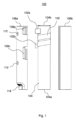
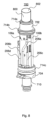
図1を参照すると、本発明の一実施形態による装置100の一例の分解側方投影図が示してある。装置100は、エアロゾル化可能材料を加熱してエアロゾル化可能材料の少なくとも1つの成分を蒸発させるためのものである。たとえば、装置100は、上述のような非燃焼加熱式製品若しくはタバコ加熱製品の一部を形成するか、又は電子タバコの一部を形成する加熱装置でもよい。
Referring to FIG. 1, there is shown an exploded side view of an
装置100は、エアロゾル化可能材料を含む消耗品を受け入れるように構成された細長い受入れ部分を画定する(これ以降コイル102と呼ばれる)導電性コイルを備える。図1に示されている例では、受入れ部分は、金属の管でもよい加熱管104を備える。たとえば、加熱管104はアルミニウム、銅、又は別の適当な導電性の材料で作成されてもよい。
加熱管104は、(遠位端部と呼ばれることがある)第1の端部104aと、(近位端部と呼ばれることがある)第2の端部104bとを有する。使用時、第1の端部104aにおいて加熱管104へと空気を受けることができ、第2の端部104bにおいて、加熱された空気及びエアロゾル化可能材料の蒸発した成分が加熱管から出て行くことができる。消耗品は、第2の端部104bを介して加熱管104の内部へと挿入することができる。図1に示されているように、第2の端部104bは、消耗品の挿入を助けるためにフレア又はテーパを備えてもよい。
加熱管104の外側表面は、酸化させられるか、被覆されるか、又はその他の方法で誘電性材料の層が提供されて加熱管104からコイル102を電気的に絶縁し、それによってコイル102を迂回する短絡を防止することができる。
The outer surface of the
加熱管104は、0.05~0.15mmの範囲の壁厚を有してもよい。たとえば、加熱管104は約0.1mmの壁厚を有してもよい。いくつかの例では、加熱管104の壁厚は加熱管104の長さに沿って実質的に均一でもよく、したがって、加熱管104はその長さに沿って実質的に均一に熱エネルギーを吸収する。他の例では、加熱管104の壁厚は加熱管104の長さに沿って変動してもよく、又は加熱管104が異なる壁厚を有する2つ以上の加熱管セグメントを備えて、加熱管104の異なる部分において異なる熱吸収特性を提供してもよい。
コイル102は第1の端部102a及び第2の端部102bを備え、加熱管104の周りにらせん構成で巻き付けられる。図1に示されている例では、コイル102は2回半巻かれ、第1の端部102a及び第2の端部102bのそれぞれにタブを備え、タブは、以下に説明するように、電源との電気接続部を(たとえば圧着結合部又ははんだ結合部によって)形成する空間を形成する。コイル102は、電源からの電流が第1の端部102aから第2の端部102bへと、又はその逆に流れたときに抵抗ヒーターとして機能する。コイル102は、fecralloy(登録商標)、アルミニウム、マンガニン、銅、鋼、コンスタンタン、ニッケル、ニクロム、ステンレス鋼、及び銀のうちの1つ又は複数から作成されてもよい。コイル102は、実質的に長方形の断面を有するワイヤで形成されてもよい。
装置100はクランプ構造体106も備える。図1に示されている実施形態では、クランプ構造体は第1のクランプ要素106a及び第2のクランプ要素106bを備える。第2のクランプ要素106bは第1のクランプ要素106aと嵌合するように構成され、それにより、第1のクランプ要素106aと第2のクランプ要素106bとがコイル102を囲む。クランプ構造体106は、高温に耐えるのに適したセラミック材料から作成されてもよい。クランプ構造体106は、材料を所望の形状に成形することによって製造されてもよい。たとえば、クランプ構造体106は熱伝導率が低いジルコニア(二酸化ジルコニウム)又は他のセラミック材料から成形され、以て装置100からの熱損失を減少させることができる。別法として、クランプ構造体106は材料を所望の形状に機械加工することによって製造されてもよく、付加製造技法を使用して製造されてもよい。他の例では、クランプ構造体106は、ポリエーテルエーテルケトン(PEEK)などの熱伝導率が低く融点が高いポリマーで形成されてもよい。
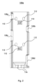
図2は、クランプ構造体106の第1のクランプ要素106aの一例の側方投影図であり、第1のクランプ要素106aの内側表面の特徴を示している。第1のクランプ要素106aは第1の係合部分108a及び第2の係合部分108bを備える。第1の係合部分108a及び第2の係合部分108bはコイル102の端部に係合して、加熱管104の周りにコイルを締め付けるように構成される。特に、(図5、図6a、及び図6bを参照して以下に説明するように)クランプ構造体106が組み立てられたとき、第1の係合部分108aはコイル102の第1の端部102aに力を加え、第2の係合部分108bはコイル102の第2の端部102bに対向する力を加える。その結果得られる対向する力は、トーションばねの作用に類似した方式でコイル102に張力を与えるように機能する。コイル102の張力により、加熱管104の外側表面にコイル102が締め付けられ、これにより、コイル102によって生成される熱エネルギーの加熱管104への(たとえば伝導及び/又は放射による)伝達が改善され、以て装置100の効率の改善、及び/又は加熱管104がエアロゾル化可能材料の成分を蒸発させるのに適した所望の温度に達するのに要する時間の短縮が可能になる。
FIG. 2 is a side projection view of an example
図2に示されている例では、係合部分108a、108bは、穴又は凹部をそれぞれ備える。コイル102の第1の端部102a及び第2の端部102bのタブは穴又は凹部のうちの1つを通って延在し、したがって、タブはクランプ構造体106の内部からクランプ構造体106の外部へと延在する。したがって、穴又は凹部は、コイル102に電流を与えてコイルに熱を生成させるために、電力を伝える導体を配線することができる経路を形成する。それぞれのタブは、上述のように係合部分108a、108bがタブに力を及ぼしてコイル102に張力を与えることができるように、係合部分108a、108bの各穴又は凹部の縁部に係合する。特に、係合部分108a、108bの凹部の深さ、並びに/又はコイル102の第1の端部102a及び第2の端部102bにおけるタブの位置は、タブ同士の間の円周方向の離隔距離が係合部分108aと係合部分108bとの間の円周方向の離隔距離よりも小さくなるように選択することができ、したがって、装置100にクランプ構造体106が設置されたとき、係合部分108a、108bはクランプ構造体106が完全に設置される前にタブと接触し、クランプ構造体106が完全に設置されるとタブを引っ張る。
In the example shown in Figure 2, the
いくつかの実施形態では、装置100は、コイル102と接触してコイルの温度を表す信号を生成するように構成された1つ又は複数の熱電対(図示せず)を備える。図2に示されている例では、クランプ構造体106の第1のクランプ要素106aは熱電対を支持するように構成された熱電対支持体110を備える。特に、熱電対支持体110はコイル102の適当な位置に熱電対をクランプするように、また熱電対とコイル102との間の接触を維持してコイル102の温度の正確な測定を可能にするクランプ力を与えるように配置される。
In some embodiments, the
熱電対が電子装置(図示せず)を制御するコイル102の温度を表す信号を提供できるようにするために、クランプ構造体102の第1のクランプ要素102aは1つ又は複数の熱電対ワイヤアパーチャ112を備え、1つ又は複数の熱電対ワイヤアパーチャ112を通して、熱電対ワイヤを(すなわち熱電対がコイル102と接触する)クランプ構造体の内部からクランプ構造体の外部(すなわち制御電子装置)へと配線することができる。いくつかの例では、図2に示されているように熱電対ワイヤアパーチャ112がそれぞれの熱電対ワイヤに設けられ、これにより、2本以上の熱電対ワイヤが所与のアパーチャを通して配線されている例と比較して、熱電対の安定性及び位置的確度の改善を実現することができる。
The
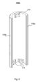
図3は、クランプ構造体106の第2のクランプ要素106bの一例の側方投影図であり、第2のクランプ要素106bの内側表面の特徴を示している。図3に示されている例では、本明細書では支持要素114と呼ばれる位置合わせ突出部が第1のクランプ要素106aの内側表面に設けられている。図2に示されているように、対応する支持要素114が第2のクランプ要素106bの内側表面に設けられる。これらの支持要素114は、装置100が組み立てられたときにクランプ構造体106内で加熱管104が同軸になること、したがって装置100内で中央に配置されることを確実にする助けとなる。さらに、クランプ構造体106と加熱管104との間の接触を支持要素114及び熱電対支持体110に限定することにより、熱伝達が減少し、したがって装置の効率を向上させることができる。
FIG. 3 is a side projection view of an example
図4は、組み立てられたときの、図1に示されている装置100の平面図である。図4に示されているように、第1のクランプ部分106a及び第2のクランプ部分106bの縁部には、第1のクランプ要素106aを第2のクランプ要素106bと位置合わせするための結合部116を設けるための特徴的形状が提供される。特に、第2のクランプ要素106bを第1のクランプ要素106aと位置合わせするために、第1のクランプ要素106aの縁部は第1のプロファイル116aを備え、第2のクランプ要素106bの縁部は、第1のプロファイル116aと合致する(すなわち一致する形状に対応する)ように構成された第2のプロファイル116bを備える。
FIG. 4 is a plan view of the
上述の例では、係合部分108a、108b、108c、108dは第1のクランプ要素106aに形成されているように述べられているが、他の実施形態では、係合部分108a、108b、108c、108dは第2のクランプ要素106bに形成されてもよい。別法として、係合部分108a、108b、108c、108dのうちのいくつかは第1のクランプ要素106aに形成されてもよく、係合部分108a、108b、108c、108dのうちの他のものは第2の係合部分106bに形成されてもよい。さらに、上述のクランプ構造体106は2つのクランプ要素を備えるが、いくつかの実施形態では、クランプ構造体は単一のクランプ要素を備えてもよく、3つ以上のクランプ要素を備えてもよい。
Although in the above example the
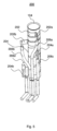
図5は、本発明の一実施形態による装置200の別の例の斜視図である。図2に示されている装置は図1に示されている装置に類似しているが、複数のコイル、この例では第1のコイル202及び第2のコイル204を含む。
FIG. 5 is a perspective view of another
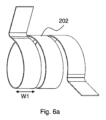
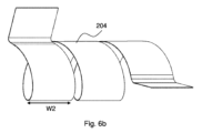
第1のコイル202は第1の端部202a及び第2の端部202bを有し、これらは(たとえば圧着結合部又ははんだ結合部によって)第1の給電ワイヤ206a及び第2の給電ワイヤ206bにそれぞれ電気的に接続されている。同様に、第2のコイル204は第1の端部204a及び第2の端部204bを有し、これらは(たとえば圧着結合部又ははんだ結合部によって)第1の給電ワイヤ206c及び第2の給電ワイヤ206dにそれぞれ電気的に接続されている。第1のコイル202及び第2のコイル204のそれぞれは、らせん構成で加熱管104の周りに巻き付けられる。給電ワイヤ206a~206dのそれぞれは、電気絶縁シースで被覆された導電性コアを備えることができる。いくつかの例では、絶縁シースはポリエーテルエーテルケトン(PEEK)から形成することができる。
The
他の例では、給電ワイヤ206a~206dは短くされるか又は省略されてもよく、第1のコイル202及び第2のコイル204は、クランプ構造体106の外側表面の近くに配置された制御回路に直接(又はより短いワイヤを介して)接続されてもよい。
In other examples, the
使用時、第1のコイル202は加熱管104の第1の加熱ゾーンを加熱するように構成され、第2のコイル204は加熱管の第2のゾーンを加熱するように構成される。第1の加熱ゾーンは加熱管104の遠位端部(すなわち第1の端部104a)から境界地点へと加熱管104に沿って延在することができ、第2の加熱ゾーンは境界地点から加熱管104の近位端部(すなわち第2の端部104b)へと延在することができる。いくつかの例では、第1の加熱ゾーンは10~15mmの範囲の長さだけ延在する。いくつかの例では、第2の加熱ゾーンは20~30mmの範囲の長さだけ延在する。
In use, the
図1を参照して上述した例の場合と同様に、第1のコイル及び第2のコイルの端部はタブを備え、タブは、給電ワイヤ206a~206dを介した電源との電気接続部を(たとえば圧着結合部又ははんだ結合部によって)形成する空間を形成する。タブは穴又は凹部のうちの1つを通って延在し、したがって、タブはクランプ構造体106の内部からクランプ構造体106の外部へと延在する。図1及び図2に示されているように、クランプ構造体は、クランプ構造体106の第1の係合部分108a及び第2の係合部分108bを参照して上述した方式でタブ、第3の係合部分108c及び第4の係合部分108dを含む。
As in the example described above with reference to FIG. 1, the ends of the first and second coils are provided with tabs that define spaces that form electrical connections (e.g., by crimp or solder connections) to a power source via
使用時、第1のコイル202又は第2のコイル204の温度が上昇する速度は、第1のコイル202又は第2のコイル204に印加される電力及び第1のコイル202又は第2のコイル204の抵抗に依存する。電源(図示せず)が充電式バッテリーである実施形態では、バッテリーによって印加される電圧は、通常は最低約2.7ボルトであるが、最大で4.2ボルトの電圧であることがあり、最大約8.6アンペアまでの電流を送り出すことができる。したがって、こうした充電式バッテリーによって供給することができる最大電力は、通常は約23ワットである。したがって、こうした充電式バッテリーによって給電されたときの、第1のコイル202又は第2のコイル204の目標抵抗は、約0.32オーム(0.35オーム±5%)でもよい。こうした抵抗により、第1のコイル202又は第2のコイル204の温度を約3秒(「ランプアップ(ramp up)」時間)で室温(すなわち約23℃)から約280℃の目標温度へと上昇させること、すなわち1秒当たり約90℃の速度で上昇させることが可能になり、これはエアロゾル化可能材料を含む消耗品を加熱するように構成された誘導ワイヤの加熱速度に匹敵する。
In use, the rate at which the temperature of the
第1のコイル202又は第2のコイル204の抵抗は、コイル材料の抵抗率に依存する。密度がより小さい材料は質量がより小さく、したがって必要とするエネルギー及び/又は加熱時間がより少ない。同様に、比熱がより小さい材料は必要とするエネルギー及び/又は加熱時間がより少ない。しかし、密度は比熱に反比例するので、両方を少なく選択することはできず、兼ね合いを見つけ出さなければならない。
The resistance of the
材料の抵抗率に関しては、加熱に必要とされるエネルギー及び/又は時間と加熱すべき表面の被覆率との間の兼ね合いを見つけ出さなければならない。抵抗率がより高い材料は必要とする材料がより少なく、したがってより少ない質量を有する(したがって加熱するのに必要とするエネルギー及び/又は時間がより少ない)が、加熱すべき表面の被覆がより狭くなり、一方抵抗率がより低い材料は必要とする材料がより多く、したがってより多くの質量を有する(したがって加熱するのに必要とするエネルギー及び/又は時間がより多い)が、加熱すべき表面の被覆がより広くなる。 With respect to material resistivity, a tradeoff must be found between the energy and/or time required for heating and the coverage of the surface to be heated. Higher resistivity materials require less material and therefore have less mass (and thus require less energy and/or time to heat) but have a narrower surface coverage to heat, while lower resistivity materials require more material and therefore have more mass (and thus require more energy and/or time to heat) but have a wider surface coverage to heat.
目標とする温度上昇が約257℃、利用可能な最大電力が約23ワットである場合、(s/mm3の単位を有する)所与の材料体積について所望の温度に達するのに要する時間tvは、この式を使用して様々な材料について計算することができる。 If the target temperature rise is about 257° C. and the maximum available power is about 23 Watts, the time t v required to reach the desired temperature for a given material volume (with units of s/ mm3 ) can be calculated for various materials using this formula.
tv=(温度上昇×比熱×密度)/電力
いくつかの例では、使用時、装置200は、第1のコイル202が第1の加熱ゾーンを第1のゾーンの目標温度まで加熱し、第2のコイル204が第2の加熱ゾーンを第2のゾーンの目標温度まで加熱するように構成される。第1の加熱ゾーンの目標温度は、約250℃~約280℃の間など、約240℃~約300℃の間の範囲でもよい。同様に、第2の加熱ゾーンの目標温度も、約250℃~約280℃の間など、約240℃~約300℃の間の範囲でもよい。
t v = (Temperature Rise x Specific Heat x Density)/Power In some examples, in use, the
いくつかの例では、使用時、装置200は、第1のコイル202が2~10秒の間、たとえば2~5秒の間など、2~40秒の間のランプアップ時間で第1の加熱ゾーンを第1の加熱ゾーンの目標温度まで加熱するように構成される。同様に、使用時、装置200は、第2のコイル204が2~10秒の間、たとえば2~5秒の間など、2~40秒の間のランプアップ時間で第2の加熱ゾーンを第2の加熱ゾーンの目標温度まで加熱するように構成される。
In some examples, in use, the
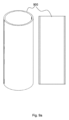
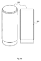
図6aには第1のコイル202の斜視図が示してあり、図6bには第2のコイル204の斜視図が示してある。
A perspective view of the
第1のコイル202及び第2のコイル204のそれぞれは、電源からの電流が第1の端部202a、204aから第2の端部202b、204bへと、又はその逆に流れたときに抵抗ヒーターとして機能する。第1のコイル202及び第2のコイル204は、fecralloy(登録商標)、アルミニウム、マンガニン、銅、鋼、コンスタンタン、ニッケル、ニクロム、ステンレス鋼、及び銀のうちの1つ又は複数から作成されてもよい。第1のコイル202は、第2のコイル204とは異なる寸法を有してもよい。第1のコイル202及び第2のコイル204は、実質的に長方形の断面を有するワイヤで形成されてもよい。
Each of the
第1のコイル202及び第2のコイル204は同じ回数の巻きを有してもよく、異なる回数の巻きを有してもよい。図6a及び図6bに示されている例では、第1のコイル202及び第2のコイル204はそれぞれ約2回半の巻きを有し、第1の端部及び第2の端部202a、202b、204a、204bのそれぞれにタブをそれぞれ備え、タブは、電源との電気接続部を(たとえば圧着結合部又ははんだ結合部によって)形成する空間を形成する。第1のコイル202及び第2のコイル204は、実質的に長方形の断面を有するワイヤでそれぞれ形成される。第1のコイル202は0.1mm±30%の範囲の厚さと、2.75mm±30%の範囲の幅W1と、約62.36mm±30%の長さとを有するワイヤで形成されて、約10.7mm2の加熱管104との接触面積、及び約0.37Ωの抵抗を提供してもよい。第2のコイル204は、0.05mm±30%の範囲の厚さと、5.95mm±30%の範囲の幅W2と、62mm±30%の範囲の長さとを有するワイヤで形成されて、約21.7mm2の加熱管104との接触面積、及び約0.36Ωの抵抗を提供してもよい。
The
上述の装置100、200は、誘導加熱構成体と性能が同様の加熱特性を有する抵抗加熱構成体を提供するが、製造がより安価及び/又は容易である。たとえば、装置100、200は、14秒~20秒の範囲など20秒未満で、加熱管104(又は加熱管104の所与のゾーン)の温度が室温から250℃(すなわち最初にうまく吹かすことを可能にするのに十分な、エアロゾル化可能材料をエアロゾル化させるのに十分に高い温度)までランプアップするように加熱管104を加熱することができ、約4~10回の連続したセッションを可能にすることができる。
The
さらに、こうした加熱構成体は装置をより小さくすることを可能にする場合があり、したがって、デバイスの全体的な寸法を必ずしも拡大することなく、より大きいフォーマットの消耗品を収容するように装置を修正することを可能にする場合がある。たとえば、装置(すなわち加熱管及びコイル)は、いわゆるデミスリムフォーマットの消耗品を収容するように修正されてもよい。 In addition, such heating components may allow the device to be made smaller, thus allowing the device to be modified to accommodate larger format consumables without necessarily increasing the overall dimensions of the device. For example, the apparatus (ie heating tubes and coils) may be modified to accommodate so-called demi-slim format consumables.
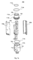
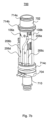
上述の装置100、200は、非燃焼加熱式製品又はタバコ加熱製品などのデバイスで使用されてもよい。たとえば、図7aは、図5を参照して上述した装置200を含むこうしたデバイス700の組立てを示す分解図であり、図7bは、装置が部分的に組み立てられた状態の同じデバイス700の斜視図である。デバイス700は装置200、膨張チャンバ702、及び清掃管704を備える。
The
膨張チャンバ702は、その中心を通る貫通穴706を有する、概して環状の構成要素である。貫通穴706は、消耗品を加熱管104に挿入することができる経路を提供する。貫通穴706は、使用時に消耗品が加熱されているときにエアロゾル化可能材料の蒸発した成分が加熱管104からデバイス700の外部に向かって進むことを可能にする出口としても機能する。いくつかの例では、装置200によって加熱されエアロゾル化可能材料から蒸発した成分を含有するガスが貫通穴706を通過するときに膨張及び冷却されることを可能にするために、貫通穴706は加熱管104より大きい直径を有してもよく、及び/又は加熱管よりも大きい直径へとテーパ付けされてもよい。
清掃管704は、加熱管104の内部をデバイス700の外部に流体連結する入口穴708を有する概して管状の構成要素であり、使用者が消耗品を吸い込んだときに入口穴708から空気を引き込むことができる。使用者は、消耗品から(1つ又は複数の)蒸発した成分を吸い込むことにより、エアロゾル化可能材料の(1つ又は複数の)蒸発した成分を吸入することが可能になり得る。(1つ又は複数の)蒸発した成分が消耗品から除去されるにつれて、入口穴708を介して、空気が加熱管104へと吸い込まれ得る。入口穴708は、清掃のための加熱管104の内部へのアクセスも可能にすることができる。
清掃管704は、図5を参照して上述した給電ワイヤ206a~206dなどの給電ワイヤを配線するためのチャネル710も含む。
膨張チャンバ702及び/又は清掃管704は熱伝導率が低いジルコニア又は他のセラミック材料で形成され、以て装置200からの熱損失を減少させることができる。他の例では、膨張チャンバ702及び/又は清掃管704は、ポリエーテルエーテルケトン(PEEK)などの熱伝導率が低く融点が高いポリマーで形成されてもよい。膨張チャンバ702及び/又は清掃管704は、材料を所望の形状に成形することによって製造されてもよい。たとえば、膨張チャンバ702及び/又は清掃管704は成形されてもよい。別法として、膨張チャンバ702及び/又は清掃管704は材料を所望の形状に機械加工することによって製造されてもよく、付加製造技法を使用して製造されてもよい。
膨張チャンバ702及び清掃管704は、(図示されていないが図9a及び図9bを参照して以下に述べる)スリーブ又はハウジング内にデバイス700を封止するための封止材を受けるように構成された溝又は凹部などのくぼみを備えてもよい。たとえば、図7a及び図7bに示されているように、膨張チャンバ702は、上方膨張チャンバOリング214aを受けるように構成された上方溝712aと、下方膨張チャンバOリング714bを受けるように構成された下方溝712bとを備え、清掃管704は、清掃管Oリング714cを受けるように構成された凹部712cを備える。
図7bに最も明確に見て取れるように、組み立てられると、クランプ構造体106の第1のクランプ要素106a及び第2のクランプ要素106bは膨張チャンバ702及び清掃管704の端部分の凹部に配置される。これらの凹部は、係合部分108a~108dが第1のコイル202及び第2のコイル204の第1の端部及び第2の端部102a~102dに係合するように、(結合部116において結合された)第1のクランプ要素106aと第2のクランプ要素106bとを一緒に保持するように機能する。凹部は、装置100、200が組み立てられたときにクランプ構造体106が装置100、200内で同軸になることを確実にする助けにもなる。
When assembled,
第1の給電ワイヤ、第2の給電ワイヤ、第3の給電ワイヤ、及び第4の給電ワイヤ206a~206dは、(たとえば圧着結合部又ははんだ結合部によって)第1のコイル202及び第2のコイル204の第1の端部及び第2の端部102a~102dに電気的に接続され、クランプ構造体106の外側の長さに沿って、また清掃管704に形成されたチャネル710を通って延在して、電源及び/又は制御回路(図示せず)に電気的に接続される。デバイス700の製造中、チャネル710は、空気又は水分の侵入を防止するために封止されてもよい。たとえば、チャネル710は給電ワイヤ206a~206dの周りに封止部を提供するように構成された封止構成要素で封止されてもよく、ゴム被覆材料又は樹脂などの封止材料で充填されるか又は部分的に充填されてもよい。いくつかの例では、熱電対ワイヤ(図示せず)も、給電ワイヤと同じ方式でチャネル710を通して配線されてもよい。
First, second, third, and
図1及び図7bに最も明確に示されているように、給電ワイヤ及び/又は熱電対ワイヤをより容易にチャネル710を通して配線することができるように、クランプ構造体106は、チャネル710へのアクセスを可能にするように構成されたへこみ118を備える。示されている例では、くぼみ118は第1のクランプ要素106aに設けられているが、他の例では、くぼみは第2のクランプ要素106b、又は別のクランプ要素に設けられてもよい。別法として、ワイヤは清掃管704の周りで外側に配線されてもよい。
As shown most clearly in FIGS. 1 and 7b, the
図8には、消耗品800が加熱管104に挿入された状態で使用されている、図2を参照して上述した装置200を備えるデバイス700が示してある。上述のように、消耗品800は装置に挿入されて加熱され、それによって消耗品800に存在するエアロゾル化可能材料に存在する成分を放出する(すなわち蒸発させる)ことができる。消耗品800の端部802は、いくつかの実施形態ではマウスピースとして機能することができ、エアロゾル化可能材料から蒸発した成分をこのマウスピースから吸い込むことができる。
FIG. 8 shows
消耗品が加熱管104に存在し、デバイスの制御装置が(1つ又は複数の)コイルに電流を流すよう電源を制御しているとき、(1つ又は複数の)コイルからの熱がエアロゾル化可能材料を加熱して、エアロゾル化可能材料の成分を蒸発させる。
When the consumable is present in the
図7a及び図7bを参照して上述したデバイス700は、下方膨張チャンバOリング214b及び清掃管Oリング214cとの間で封止部を形成するように構成されたスリーブ内に収容されてもよい。スリーブは、装置100、200とデバイス700の外側表面との間である程度の断熱を可能にする。図9a及び図9bには、デバイス700で使用されることがあるスリーブの例が示してある。図9aに示されている例では、スリーブ900は単一壁のスリーブである。図9bに示されている例では、スリーブ902は二重壁スリーブであり、二重壁スリーブ内には、追加的な断熱を可能にする空気、別のガス、又は部分的な真空を備える間隙904が存在する。いくつかの例では、図9bに示されているスリーブ902によって可能になる追加的な断熱が有利な場合がある。しかし、追加的な断熱が必要とされない例では、製造がより容易及び安価である場合がある図9aに示されているスリーブ900が好ましいことがある。
The
図10は、図1及び5を参照して上述した装置などの装置を製造する方法1000を示す簡略化されたブロック図である。 FIG. 10 is a simplified block diagram illustrating a method 1000 of manufacturing a device such as the devices described above with reference to FIGS.
ブロック1002では、エアロゾル化可能材料を含む消耗品を受け入れるように構成された細長い受入れ部分の周りに導電性コイルを形成する。導電性コイルは、第1の端部と、第1の端部の反対側の第2の端部とを有する。 At block 1002, a conductive coil is formed around an elongated receiving portion configured to receive a consumable containing an aerosolizable material. The conductive coil has a first end and a second end opposite the first end.
ブロック1004では、導電性コイルにクランプ構造体を設置する。クランプ構造体は、第1の力を第1の端部に加えるように構成された第1の係合部分と、第1の力に対向する第2の力を第2の端部に加えるように構成された第2の係合部分とを備えて、導電性コイルに張力を与える。 At block 1004, a clamp structure is placed on the conductive coil. The clamp structure includes a first engaging portion configured to apply a first force to the first end and a second engaging portion configured to apply a second force to the second end opposite the first force to tension the conductive coil.
本明細書に記載の種々の実施形態は、特許請求された特徴の理解及び教示を助けるためだけに提示されている。これらの実施形態は、実施形態の単なる代表的なサンプルとして提供されており、網羅的及び/又は排他的ではない。本明細書に記載の利点、実施形態、例、機能、特徴、構造、及び/又は他の側面は、特許請求の範囲によって定義された本発明の範囲に対する限定、又は特許請求の範囲の均等物に対する限定と考えられるべきではなく、特許請求された発明の範囲から逸脱しない限り、他の実施形態が利用されてもよく、修正が加えられてもよいことを理解されたい。本発明の種々の実施形態は、本明細書に具体的に記載されたもの以外の開示された要素、構成要素、特徴、部品、ステップ、手段などの適当な組合せを適切に備えるか、それらから構成されるか、又は本質的にそれらから構成されてもよい。加えて、本開示は、現在特許請求されていないが将来的に特許請求され得る他の発明を含んでもよい。 The various embodiments described herein are presented only to assist in understanding and teaching the claimed features. These embodiments are provided merely as a representative sample of embodiments and are not exhaustive and/or exclusive. None of the advantages, embodiments, examples, functions, features, structures, and/or other aspects described herein should be considered limitations on the scope of the invention as defined by the claims, or on the equivalents of the claims, and it should be understood that other embodiments may be utilized and modifications may be made without departing from the scope of the claimed invention. Various embodiments of the invention may suitably comprise, consist of, or consist essentially of any suitable combination of the disclosed elements, components, features, parts, steps, means, etc. other than those specifically described herein. Additionally, the present disclosure may include other inventions that are not currently claimed but may be claimed in the future.
Claims (36)
エアロゾル化可能材料を含む消耗品を受け入れるように構成された細長い受入れ部分を画定する導電性コイルであり、前記導電性コイルが、第1の端部と、前記第1の端部の反対側の第2の端部とを備える、導電性コイルと、
第1の力を前記第1の端部に加えるように構成された第1の係合部分と、前記第1の力に対向する第2の力を前記第2の端部に加えるように構成された第2の係合部分とを備え、以て前記導電性コイルに張力を与える、クランプ構造体と
を具備する、装置。 An apparatus configured to heat an aerosolizable material to vaporize at least one component of the aerosolizable material, comprising:
an electrically conductive coil defining an elongated receiving portion configured to receive a consumable comprising an aerosolizable material, said electrically conductive coil comprising a first end and a second end opposite said first end;
and a clamp structure comprising a first engagement portion configured to apply a first force to the first end and a second engagement portion configured to apply a second force to the second end opposite the first force, thereby tensioning the conductive coil.
前記第1の係合部分及び前記第2の係合部分が、それぞれの前記タブが配置される穴又は凹部をそれぞれ備え、
前記タブが、前記クランプ構造体の内部から前記クランプ構造体の外部へと延在して、それぞれの前記穴又は凹部の縁部に係合する、請求項1~10のいずれか一項に記載の装置。 said conductive coil comprising a tab on each of said first end and said second end;
said first engaging portion and said second engaging portion each comprising a hole or recess in which said respective tab is disposed;
11. The apparatus of any one of claims 1-10, wherein the tabs extend from the interior of the clamping structure to the exterior of the clamping structure to engage edges of the respective holes or recesses.
前記装置が、
前記第2の導電性コイルの前記第1の端部に電気的に接続された第3の給電ワイヤと、
前記第2の導電性コイルの前記第2の端部に電気的に接続された第4の給電ワイヤと
を備え、
前記第1の給電ワイヤ及び前記第2の給電ワイヤが前記第1の導電性コイルに電流を流すように構成され、前記第3の給電ワイヤ及び前記第4の給電ワイヤが前記第2の導電性コイルに電流を流すように構成されている、請求項12~16のいずれか一項に記載の装置。 a first feed wire electrically connected to the first end of the first conductive coil and a second feed wire electrically connected to the second end of the first conductive coil;
said device comprising:
a third feed wire electrically connected to the first end of the second conductive coil;
a fourth feed wire electrically connected to the second end of the second conductive coil;
17. The apparatus of any one of claims 12-16, wherein the first feed wire and the second feed wire are configured to conduct current through the first conductive coil, and the third feed wire and the fourth feed wire are configured to conduct current through the second conductive coil.
前記受入れ部分に消耗品を受け入れるためのアクセスを可能にし、前記受入れ部分から出て行く空気経路を形成するように構成された膨張チャンバと
を備え、
前記清掃管及び前記膨張チャンバが、前記クランプ構造体の端部を受け入れて前記第1のクランプ要素を前記第2のクランプ要素と接触した状態に保持し、それによって前記導電性コイルを前記受入れ部分にクランプするようにそれぞれ構成されている、請求項2~27のいずれか一項に記載の装置。 a cleaning tube configured to form an air path to the receiving portion;
an expansion chamber configured to provide access to the receiving portion for receiving a consumable and to form an air path exiting the receiving portion;
28. The apparatus of any one of claims 2-27, wherein the cleaning tube and the expansion chamber are each configured to receive an end of the clamping structure to hold the first clamping element in contact with the second clamping element, thereby clamping the conductive coil to the receiving portion.
前記スリーブと前記清掃管との間に空気封止部を形成するように構成された第1の封止構成要素と、
前記スリーブと前記膨張チャンバとの間に空気封止部を形成するように構成された第2の封止構成要素と
を備える、請求項28に記載の装置。 a sleeve configured to house the clamp structure and the conductive coil;
a first sealing component configured to form an air seal between the sleeve and the cleaning tube;
29. The device of Claim 28, comprising a second sealing component configured to form an air seal between the sleeve and the expansion chamber.
エアロゾル化可能材料を含む消耗品を受け入れるように構成された細長い受入れ部分の周りに導電性コイルを形成するステップであり、前記導電性コイルが、第1の端部と、前記第1の端部の反対側の第2の端部とを備える、ステップと、
前記導電性コイルにクランプ構造体を設置するステップであり、前記クランプ構造体が、第1の力を前記第1の端部に加えるように構成された第1の係合部分と、前記第1の力に対向する第2の力を前記第2の端部に加えるように構成された第2の係合部分とを備えて、前記導電性コイルに張力を与える、ステップと
を含む、方法。 A method of manufacturing a device configured to heat an aerosolizable material, comprising:
forming a conductive coil about an elongated receiving portion configured to receive a consumable comprising an aerosolizable material, said conductive coil comprising a first end and a second end opposite said first end;
placing a clamp structure on the conductive coil, the clamp structure comprising a first engaging portion configured to apply a first force to the first end and a second engaging portion configured to apply a second force to the second end opposite the first force to tension the conductive coil.
Applications Claiming Priority (3)
| Application Number | Priority Date | Filing Date | Title |
|---|---|---|---|
| US202062705430P | 2020-06-26 | 2020-06-26 | |
| US62/705,430 | 2020-06-26 | ||
| PCT/EP2021/067432 WO2021260155A1 (en) | 2020-06-26 | 2021-06-24 | Apparatus for heating aerosolisable material |
Publications (2)
| Publication Number | Publication Date |
|---|---|
| JP2023531663A true JP2023531663A (en) | 2023-07-25 |
| JP7607059B2 JP7607059B2 (en) | 2024-12-26 |
Family
ID=76662498
Family Applications (1)
| Application Number | Title | Priority Date | Filing Date |
|---|---|---|---|
| JP2022578834A Active JP7607059B2 (en) | 2020-06-26 | 2021-06-24 | Apparatus for heating an aerosolizable material and method for manufacturing the same - Patents.com |
Country Status (5)
| Country | Link |
|---|---|
| US (1) | US20230337740A1 (en) |
| EP (1) | EP4171281B1 (en) |
| JP (1) | JP7607059B2 (en) |
| PL (1) | PL4171281T3 (en) |
| WO (1) | WO2021260155A1 (en) |
Citations (5)
| Publication number | Priority date | Publication date | Assignee | Title |
|---|---|---|---|---|
| US20170325510A1 (en) * | 2016-07-29 | 2017-11-16 | Shenzhen First Union Technology Co., Ltd. | Heating device for electronic cigarette and atomizer having same |
| WO2019111103A1 (en) * | 2017-12-08 | 2019-06-13 | Rai Strategic Holdings, Inc. | Quasi-resonant flyback converter for an induction-based aerosol delivery device |
| CN210158006U (en) * | 2019-04-16 | 2020-03-20 | 常州市派腾电子技术服务有限公司 | Atomization component, atomization device and electronic cigarette |
| CN210353181U (en) * | 2019-06-11 | 2020-04-21 | 深圳市新宜康科技股份有限公司 | Electromagnetic induction heating components |
| CN210782935U (en) * | 2019-07-04 | 2020-06-19 | 深圳市合元科技有限公司 | Aerosol-generating system |
Family Cites Families (11)
| Publication number | Priority date | Publication date | Assignee | Title |
|---|---|---|---|---|
| DE102013212205B4 (en) * | 2013-06-26 | 2024-02-08 | Türk & Hillinger GmbH | Process for producing an electric heating cartridge |
| TWI666993B (en) * | 2014-05-21 | 2019-08-01 | Philip Morris Products S. A. | Inductive heating device and system for aerosol generation |
| PL3193643T5 (en) * | 2014-09-17 | 2024-01-29 | Fontem Holdings 4 B.V. | Device for storing and vaporizing liquid media |
| WO2017000239A1 (en) * | 2015-06-30 | 2017-01-05 | 深圳麦克韦尔股份有限公司 | Electronic cigarette, atomization device thereof and assembling method of atomization device |
| US11229089B2 (en) * | 2016-05-18 | 2022-01-18 | Physical Systems, Inc. | Self fixturing heater and method for accelerating nutplate adhesive curing |
| RU2731533C2 (en) * | 2016-05-31 | 2020-09-04 | Филип Моррис Продактс С.А. | Heater and wick assembly for aerosol generating system |
| US11272741B2 (en) * | 2018-01-03 | 2022-03-15 | Cqens Technologies Inc. | Heat-not-burn device and method |
| US11265974B2 (en) * | 2018-08-27 | 2022-03-01 | Rai Strategic Holdings, Inc. | Aerosol delivery device with integrated thermal conductor |
| CN209376679U (en) * | 2018-09-28 | 2019-09-13 | 深圳市合元科技有限公司 | Bake smoking set |
| US20220386698A1 (en) * | 2019-07-04 | 2022-12-08 | Philip Morris Products S.A. | Inductive heating arrangement with segmented inductive heating element |
| CN211910548U (en) * | 2020-01-13 | 2020-11-13 | 深圳市合元科技有限公司 | Aerosol generator and heater |
-
2021
- 2021-06-24 EP EP21735710.2A patent/EP4171281B1/en active Active
- 2021-06-24 US US18/003,008 patent/US20230337740A1/en active Pending
- 2021-06-24 WO PCT/EP2021/067432 patent/WO2021260155A1/en not_active Ceased
- 2021-06-24 JP JP2022578834A patent/JP7607059B2/en active Active
- 2021-06-24 PL PL21735710.2T patent/PL4171281T3/en unknown
Patent Citations (5)
| Publication number | Priority date | Publication date | Assignee | Title |
|---|---|---|---|---|
| US20170325510A1 (en) * | 2016-07-29 | 2017-11-16 | Shenzhen First Union Technology Co., Ltd. | Heating device for electronic cigarette and atomizer having same |
| WO2019111103A1 (en) * | 2017-12-08 | 2019-06-13 | Rai Strategic Holdings, Inc. | Quasi-resonant flyback converter for an induction-based aerosol delivery device |
| CN210158006U (en) * | 2019-04-16 | 2020-03-20 | 常州市派腾电子技术服务有限公司 | Atomization component, atomization device and electronic cigarette |
| CN210353181U (en) * | 2019-06-11 | 2020-04-21 | 深圳市新宜康科技股份有限公司 | Electromagnetic induction heating components |
| CN210782935U (en) * | 2019-07-04 | 2020-06-19 | 深圳市合元科技有限公司 | Aerosol-generating system |
Also Published As
| Publication number | Publication date |
|---|---|
| PL4171281T3 (en) | 2024-11-18 |
| EP4171281A1 (en) | 2023-05-03 |
| JP7607059B2 (en) | 2024-12-26 |
| EP4171281B1 (en) | 2024-08-21 |
| KR20230015440A (en) | 2023-01-31 |
| US20230337740A1 (en) | 2023-10-26 |
| WO2021260155A1 (en) | 2021-12-30 |
Similar Documents
| Publication | Publication Date | Title |
|---|---|---|
| JP6267793B2 (en) | Device for heating smoking material | |
| CN109076650A (en) | Device and method for heating smokeable material | |
| JP2023100948A (en) | Aerosol delivery device | |
| JP2022524408A (en) | Aerosol supply device | |
| JP2025100566A (en) | Aerosol Delivery Device | |
| JP2025179235A (en) | Apparatus for heating an aerosolizable material | |
| JP2025166186A (en) | Apparatus for heating an aerosolizable material | |
| JP7607059B2 (en) | Apparatus for heating an aerosolizable material and method for manufacturing the same - Patents.com | |
| JP2023542102A (en) | Aerosol delivery device | |
| JP2025066733A (en) | Aerosol Delivery Device | |
| KR102933837B1 (en) | Aerosol delivery device | |
| TW202038768A (en) | Apparatus for aerosol generating system | |
| KR102959677B1 (en) | Device for heating aerosolizable materials | |
| KR20260061547A (en) | Aerosol provision device |
Legal Events
| Date | Code | Title | Description |
|---|---|---|---|
| A621 | Written request for application examination |
Free format text: JAPANESE INTERMEDIATE CODE: A621 Effective date: 20230216 |
|
| A131 | Notification of reasons for refusal |
Free format text: JAPANESE INTERMEDIATE CODE: A131 Effective date: 20240416 |
|
| A601 | Written request for extension of time |
Free format text: JAPANESE INTERMEDIATE CODE: A601 Effective date: 20240702 |
|
| A521 | Request for written amendment filed |
Free format text: JAPANESE INTERMEDIATE CODE: A523 Effective date: 20241011 |
|
| TRDD | Decision of grant or rejection written | ||
| A01 | Written decision to grant a patent or to grant a registration (utility model) |
Free format text: JAPANESE INTERMEDIATE CODE: A01 Effective date: 20241203 |
|
| A61 | First payment of annual fees (during grant procedure) |
Free format text: JAPANESE INTERMEDIATE CODE: A61 Effective date: 20241216 |
|
| R150 | Certificate of patent or registration of utility model |
Ref document number: 7607059 Country of ref document: JP Free format text: JAPANESE INTERMEDIATE CODE: R150 |