JP2023543473A - Batteries, battery manufacturing methods, and power consumption devices - Google Patents
Batteries, battery manufacturing methods, and power consumption devices Download PDFInfo
- Publication number
- JP2023543473A JP2023543473A JP2023519748A JP2023519748A JP2023543473A JP 2023543473 A JP2023543473 A JP 2023543473A JP 2023519748 A JP2023519748 A JP 2023519748A JP 2023519748 A JP2023519748 A JP 2023519748A JP 2023543473 A JP2023543473 A JP 2023543473A
- Authority
- JP
- Japan
- Prior art keywords
- battery
- liquid injection
- injection hole
- electrode terminal
- battery cells
- Prior art date
- Legal status (The legal status is an assumption and is not a legal conclusion. Google has not performed a legal analysis and makes no representation as to the accuracy of the status listed.)
- Granted
Links
Images





Classifications
-
- H—ELECTRICITY
- H01—ELECTRIC ELEMENTS
- H01M—PROCESSES OR MEANS, e.g. BATTERIES, FOR THE DIRECT CONVERSION OF CHEMICAL ENERGY INTO ELECTRICAL ENERGY
- H01M10/00—Secondary cells; Manufacture thereof
- H01M10/60—Heating or cooling; Temperature control
- H01M10/61—Types of temperature control
- H01M10/613—Cooling or keeping cold
-
- H—ELECTRICITY
- H01—ELECTRIC ELEMENTS
- H01M—PROCESSES OR MEANS, e.g. BATTERIES, FOR THE DIRECT CONVERSION OF CHEMICAL ENERGY INTO ELECTRICAL ENERGY
- H01M50/00—Constructional details or processes of manufacture of the non-active parts of electrochemical cells other than fuel cells, e.g. hybrid cells
- H01M50/60—Arrangements or processes for filling or topping-up with liquids; Arrangements or processes for draining liquids from casings
- H01M50/609—Arrangements or processes for filling with liquid, e.g. electrolytes
- H01M50/627—Filling ports
- H01M50/636—Closing or sealing filling ports, e.g. using lids
-
- H—ELECTRICITY
- H01—ELECTRIC ELEMENTS
- H01M—PROCESSES OR MEANS, e.g. BATTERIES, FOR THE DIRECT CONVERSION OF CHEMICAL ENERGY INTO ELECTRICAL ENERGY
- H01M50/00—Constructional details or processes of manufacture of the non-active parts of electrochemical cells other than fuel cells, e.g. hybrid cells
- H01M50/60—Arrangements or processes for filling or topping-up with liquids; Arrangements or processes for draining liquids from casings
- H01M50/609—Arrangements or processes for filling with liquid, e.g. electrolytes
-
- H—ELECTRICITY
- H01—ELECTRIC ELEMENTS
- H01M—PROCESSES OR MEANS, e.g. BATTERIES, FOR THE DIRECT CONVERSION OF CHEMICAL ENERGY INTO ELECTRICAL ENERGY
- H01M10/00—Secondary cells; Manufacture thereof
- H01M10/04—Construction or manufacture in general
-
- H—ELECTRICITY
- H01—ELECTRIC ELEMENTS
- H01M—PROCESSES OR MEANS, e.g. BATTERIES, FOR THE DIRECT CONVERSION OF CHEMICAL ENERGY INTO ELECTRICAL ENERGY
- H01M10/00—Secondary cells; Manufacture thereof
- H01M10/04—Construction or manufacture in general
- H01M10/0422—Cells or battery with cylindrical casing
-
- H—ELECTRICITY
- H01—ELECTRIC ELEMENTS
- H01M—PROCESSES OR MEANS, e.g. BATTERIES, FOR THE DIRECT CONVERSION OF CHEMICAL ENERGY INTO ELECTRICAL ENERGY
- H01M10/00—Secondary cells; Manufacture thereof
- H01M10/05—Accumulators with non-aqueous electrolyte
- H01M10/052—Li-accumulators
- H01M10/0525—Rocking-chair batteries, i.e. batteries with lithium insertion or intercalation in both electrodes; Lithium-ion batteries
-
- H—ELECTRICITY
- H01—ELECTRIC ELEMENTS
- H01M—PROCESSES OR MEANS, e.g. BATTERIES, FOR THE DIRECT CONVERSION OF CHEMICAL ENERGY INTO ELECTRICAL ENERGY
- H01M50/00—Constructional details or processes of manufacture of the non-active parts of electrochemical cells other than fuel cells, e.g. hybrid cells
- H01M50/10—Primary casings; Jackets or wrappings
- H01M50/102—Primary casings; Jackets or wrappings characterised by their shape or physical structure
- H01M50/107—Primary casings; Jackets or wrappings characterised by their shape or physical structure having curved cross-section, e.g. round or elliptic
-
- H—ELECTRICITY
- H01—ELECTRIC ELEMENTS
- H01M—PROCESSES OR MEANS, e.g. BATTERIES, FOR THE DIRECT CONVERSION OF CHEMICAL ENERGY INTO ELECTRICAL ENERGY
- H01M50/00—Constructional details or processes of manufacture of the non-active parts of electrochemical cells other than fuel cells, e.g. hybrid cells
- H01M50/20—Mountings; Secondary casings or frames; Racks, modules or packs; Suspension devices; Shock absorbers; Transport or carrying devices; Holders
- H01M50/204—Racks, modules or packs for multiple batteries or multiple cells
- H01M50/207—Racks, modules or packs for multiple batteries or multiple cells characterised by their shape
- H01M50/213—Racks, modules or packs for multiple batteries or multiple cells characterised by their shape adapted for cells having curved cross-section, e.g. round or elliptic
-
- H—ELECTRICITY
- H01—ELECTRIC ELEMENTS
- H01M—PROCESSES OR MEANS, e.g. BATTERIES, FOR THE DIRECT CONVERSION OF CHEMICAL ENERGY INTO ELECTRICAL ENERGY
- H01M50/00—Constructional details or processes of manufacture of the non-active parts of electrochemical cells other than fuel cells, e.g. hybrid cells
- H01M50/20—Mountings; Secondary casings or frames; Racks, modules or packs; Suspension devices; Shock absorbers; Transport or carrying devices; Holders
- H01M50/249—Mountings; Secondary casings or frames; Racks, modules or packs; Suspension devices; Shock absorbers; Transport or carrying devices; Holders specially adapted for aircraft or vehicles, e.g. cars or trains
-
- H—ELECTRICITY
- H01—ELECTRIC ELEMENTS
- H01M—PROCESSES OR MEANS, e.g. BATTERIES, FOR THE DIRECT CONVERSION OF CHEMICAL ENERGY INTO ELECTRICAL ENERGY
- H01M50/00—Constructional details or processes of manufacture of the non-active parts of electrochemical cells other than fuel cells, e.g. hybrid cells
- H01M50/30—Arrangements for facilitating escape of gases
-
- H—ELECTRICITY
- H01—ELECTRIC ELEMENTS
- H01M—PROCESSES OR MEANS, e.g. BATTERIES, FOR THE DIRECT CONVERSION OF CHEMICAL ENERGY INTO ELECTRICAL ENERGY
- H01M50/00—Constructional details or processes of manufacture of the non-active parts of electrochemical cells other than fuel cells, e.g. hybrid cells
- H01M50/50—Current conducting connections for cells or batteries
-
- H—ELECTRICITY
- H01—ELECTRIC ELEMENTS
- H01M—PROCESSES OR MEANS, e.g. BATTERIES, FOR THE DIRECT CONVERSION OF CHEMICAL ENERGY INTO ELECTRICAL ENERGY
- H01M50/00—Constructional details or processes of manufacture of the non-active parts of electrochemical cells other than fuel cells, e.g. hybrid cells
- H01M50/50—Current conducting connections for cells or batteries
- H01M50/502—Interconnectors for connecting terminals of adjacent batteries; Interconnectors for connecting cells outside a battery casing
- H01M50/503—Interconnectors for connecting terminals of adjacent batteries; Interconnectors for connecting cells outside a battery casing characterised by the shape of the interconnectors
-
- H—ELECTRICITY
- H01—ELECTRIC ELEMENTS
- H01M—PROCESSES OR MEANS, e.g. BATTERIES, FOR THE DIRECT CONVERSION OF CHEMICAL ENERGY INTO ELECTRICAL ENERGY
- H01M50/00—Constructional details or processes of manufacture of the non-active parts of electrochemical cells other than fuel cells, e.g. hybrid cells
- H01M50/50—Current conducting connections for cells or batteries
- H01M50/502—Interconnectors for connecting terminals of adjacent batteries; Interconnectors for connecting cells outside a battery casing
- H01M50/514—Methods for interconnecting adjacent batteries or cells
- H01M50/516—Methods for interconnecting adjacent batteries or cells by welding, soldering or brazing
-
- H—ELECTRICITY
- H01—ELECTRIC ELEMENTS
- H01M—PROCESSES OR MEANS, e.g. BATTERIES, FOR THE DIRECT CONVERSION OF CHEMICAL ENERGY INTO ELECTRICAL ENERGY
- H01M50/00—Constructional details or processes of manufacture of the non-active parts of electrochemical cells other than fuel cells, e.g. hybrid cells
- H01M50/50—Current conducting connections for cells or batteries
- H01M50/543—Terminals
- H01M50/547—Terminals characterised by the disposition of the terminals on the cells
- H01M50/548—Terminals characterised by the disposition of the terminals on the cells on opposite sides of the cell
-
- H—ELECTRICITY
- H01—ELECTRIC ELEMENTS
- H01M—PROCESSES OR MEANS, e.g. BATTERIES, FOR THE DIRECT CONVERSION OF CHEMICAL ENERGY INTO ELECTRICAL ENERGY
- H01M50/00—Constructional details or processes of manufacture of the non-active parts of electrochemical cells other than fuel cells, e.g. hybrid cells
- H01M50/50—Current conducting connections for cells or batteries
- H01M50/543—Terminals
- H01M50/552—Terminals characterised by their shape
- H01M50/559—Terminals adapted for cells having curved cross-section, e.g. round, elliptic or button cells
-
- H—ELECTRICITY
- H01—ELECTRIC ELEMENTS
- H01M—PROCESSES OR MEANS, e.g. BATTERIES, FOR THE DIRECT CONVERSION OF CHEMICAL ENERGY INTO ELECTRICAL ENERGY
- H01M50/00—Constructional details or processes of manufacture of the non-active parts of electrochemical cells other than fuel cells, e.g. hybrid cells
- H01M50/50—Current conducting connections for cells or batteries
- H01M50/543—Terminals
- H01M50/564—Terminals characterised by their manufacturing process
- H01M50/566—Terminals characterised by their manufacturing process by welding, soldering or brazing
-
- H—ELECTRICITY
- H01—ELECTRIC ELEMENTS
- H01M—PROCESSES OR MEANS, e.g. BATTERIES, FOR THE DIRECT CONVERSION OF CHEMICAL ENERGY INTO ELECTRICAL ENERGY
- H01M50/00—Constructional details or processes of manufacture of the non-active parts of electrochemical cells other than fuel cells, e.g. hybrid cells
- H01M50/60—Arrangements or processes for filling or topping-up with liquids; Arrangements or processes for draining liquids from casings
- H01M50/609—Arrangements or processes for filling with liquid, e.g. electrolytes
- H01M50/627—Filling ports
-
- H—ELECTRICITY
- H01—ELECTRIC ELEMENTS
- H01M—PROCESSES OR MEANS, e.g. BATTERIES, FOR THE DIRECT CONVERSION OF CHEMICAL ENERGY INTO ELECTRICAL ENERGY
- H01M2220/00—Batteries for particular applications
- H01M2220/20—Batteries in motive systems, e.g. vehicle, ship, plane
-
- Y—GENERAL TAGGING OF NEW TECHNOLOGICAL DEVELOPMENTS; GENERAL TAGGING OF CROSS-SECTIONAL TECHNOLOGIES SPANNING OVER SEVERAL SECTIONS OF THE IPC; TECHNICAL SUBJECTS COVERED BY FORMER USPC CROSS-REFERENCE ART COLLECTIONS [XRACs] AND DIGESTS
- Y02—TECHNOLOGIES OR APPLICATIONS FOR MITIGATION OR ADAPTATION AGAINST CLIMATE CHANGE
- Y02E—REDUCTION OF GREENHOUSE GAS [GHG] EMISSIONS, RELATED TO ENERGY GENERATION, TRANSMISSION OR DISTRIBUTION
- Y02E60/00—Enabling technologies; Technologies with a potential or indirect contribution to GHG emissions mitigation
- Y02E60/10—Energy storage using batteries
-
- Y—GENERAL TAGGING OF NEW TECHNOLOGICAL DEVELOPMENTS; GENERAL TAGGING OF CROSS-SECTIONAL TECHNOLOGIES SPANNING OVER SEVERAL SECTIONS OF THE IPC; TECHNICAL SUBJECTS COVERED BY FORMER USPC CROSS-REFERENCE ART COLLECTIONS [XRACs] AND DIGESTS
- Y02—TECHNOLOGIES OR APPLICATIONS FOR MITIGATION OR ADAPTATION AGAINST CLIMATE CHANGE
- Y02P—CLIMATE CHANGE MITIGATION TECHNOLOGIES IN THE PRODUCTION OR PROCESSING OF GOODS
- Y02P70/00—Climate change mitigation technologies in the production process for final industrial or consumer products
- Y02P70/50—Manufacturing or production processes characterised by the final manufactured product
Landscapes
- Chemical & Material Sciences (AREA)
- Chemical Kinetics & Catalysis (AREA)
- Electrochemistry (AREA)
- General Chemical & Material Sciences (AREA)
- Engineering & Computer Science (AREA)
- Manufacturing & Machinery (AREA)
- Aviation & Aerospace Engineering (AREA)
- Materials Engineering (AREA)
- Connection Of Batteries Or Terminals (AREA)
- Filling, Topping-Up Batteries (AREA)
- Sealing Battery Cases Or Jackets (AREA)
Abstract

本出願は、電池、電池の作製方法及び電力消費装置に関し、該電池は少なくとも二つの電池セルを含み、電池セルは電池セルの長手方向の両側の端部に設置された電極端子を含み、ここで、一方側の電極端子は電池セルの長手方向に沿って電解液を注入するための注液孔が設けられており、二つの電池セルの注液孔が設けられている電極端子は電池セルの長手方向に沿って対向して設置され、且つ溶接接続される。本出願の電池は、注液孔を電極端子に設置し、注液孔がエンドキャップの空間を占有せず、それによって電極端子のサイズを大きくし、電極端子の電流通過面積を増加させることができる。かつ、追加のシール工程を行う必要がなく、電極端子自体により電池の全体的なシールを直接的に実現し、コストを低減させ、生産効率を向上させる。
The present application relates to a battery, a method for manufacturing the battery, and a power consumption device, the battery including at least two battery cells, the battery cell including electrode terminals installed at both longitudinal ends of the battery cell, The electrode terminal on one side is provided with an injection hole for injecting electrolyte along the longitudinal direction of the battery cell, and the electrode terminals with injection holes for the two battery cells are provided with an injection hole for injecting electrolyte along the longitudinal direction of the battery cell. are installed oppositely along the longitudinal direction and are connected by welding. In the battery of the present application, the liquid injection hole is installed in the electrode terminal, and the liquid injection hole does not occupy the space of the end cap, thereby increasing the size of the electrode terminal and the current passing area of the electrode terminal. can. Moreover, there is no need to perform an additional sealing process, and the electrode terminal itself directly realizes the overall sealing of the battery, reducing costs and improving production efficiency.
Description
本出願は、エネルギー貯蔵デバイスの技術分野に関し、特に電池、電池の作製方法及び電力消費装置に関する。 TECHNICAL FIELD This application relates to the technical field of energy storage devices, and in particular to batteries, methods of making batteries, and power consumption devices.
省エネと排出削減は、自動車産業の持続可能な発展のカギである。このような場合、電動車両は、その省エネと環境保護の優位性のため、自動車産業の持続可能な発展の重要な構成部分となっている。電動車両にとって、電池技術は、その発展に関わる重要な要素である。 Energy conservation and emission reduction are key to the sustainable development of the automotive industry. In this case, electric vehicles have become an important component of the sustainable development of the automobile industry due to their energy-saving and environmental protection advantages. Battery technology is an important element in the development of electric vehicles.
電池の生産過程では、電池セル内に電解液を注入する必要がある。従来技術では、電池セルのエンドキャップに注液孔を開設し、注液孔を介して電解を注入した後、注液孔をシールする必要があり、工程が複雑であり、コストが高い。 During the battery production process, it is necessary to inject electrolyte into the battery cells. In the conventional technology, it is necessary to open a liquid injection hole in the end cap of a battery cell, inject electrolyte through the liquid injection hole, and then seal the liquid injection hole, resulting in a complicated process and high cost.
上記問題を解決するために、本出願は電池を提供し、その注液孔はエンドキャップ空間を占有せず、エンドキャップ上の他の素子に十分で柔軟な設置方式及び配置スペースを提供することができ、エンドキャップの構造強度に影響を与えず、かつ注液孔に対して追加のシール工程を行う必要がなく、生産効率が高く、コストが低い。 In order to solve the above problems, the present application provides a battery whose filling hole does not occupy the end cap space, and provides sufficient and flexible installation method and arrangement space for other elements on the end cap. It does not affect the structural strength of the end cap, and there is no need to perform an additional sealing process for the liquid injection hole, resulting in high production efficiency and low cost.
本出願の実施例の第1の態様によれば、電池を提供する。該電池は、少なくとも二つの電池セルを含み、電池セルは電池セルの長手方向の両側の端部に設置された電極端子を含み、ここで、一方側の電極端子に電池セルの長手方向に沿って電解液を注入するための注液孔が設けられており、二つの前記電池セルの前記電極端子は前記電池セルの長手方向に沿って対向して設置され、かつ溶接接続されることによって、前記注液孔をシールする。 According to a first aspect of embodiments of the present application, a battery is provided. The battery includes at least two battery cells, and the battery cell includes electrode terminals installed at both ends of the battery cell in the longitudinal direction, and here, one electrode terminal is provided with a terminal along the longitudinal direction of the battery cell. A liquid injection hole is provided for injecting an electrolyte solution, and the electrode terminals of the two battery cells are installed facing each other along the longitudinal direction of the battery cells and are connected by welding. Seal the liquid injection hole.
注液孔を電極端子に設置し、注液孔がエンドキャップの空間を占有せず、他の素子の設置を容易にすることができ、例えば電極端子のサイズを大きくし、電極端子の電流通過面積を増加させることができる。注液孔が設けられている二つの電極端子を対向して設置し、且つ溶接接続し、追加のシール工程を行う必要がなく、電極端子自体により電池の全体的なシールを直接的に実現し、生産効率を向上させ、コストを低減させる。 The liquid injection hole is installed in the electrode terminal, and the liquid injection hole does not occupy the space of the end cap, making it easier to install other elements. For example, the size of the electrode terminal can be increased, and the current passing through the electrode terminal can be The area can be increased. Two electrode terminals with injection holes are installed facing each other and connected by welding, and the electrode terminal itself directly realizes the overall sealing of the battery without the need for an additional sealing process. , improve production efficiency and reduce costs.
いくつかの実施例において、注液孔を電極端子の中心位置に位置させることによって、二つの電池セルの注液孔の連通設置を容易にする。 In some embodiments, the liquid injection hole is located at the center of the electrode terminal, thereby facilitating the communication installation of the liquid injection holes of two battery cells.
電極端子の中心位置に注液孔を設置し、電極端子の溶接による注液孔への影響を回避することができ、二つの電極端子が突き合わせる時、二つの注液孔の間の連通を容易にすることもでき、それによって、二つの電池セルの間の電解液は相補的かつバランスになる。 The liquid injection hole is installed at the center of the electrode terminal, which can avoid the effect of welding the electrode terminal on the liquid injection hole, and prevents communication between the two liquid injection holes when the two electrode terminals butt each other. It can also be facilitated so that the electrolyte between the two battery cells is complementary and balanced.
いくつかの実施例において、注液孔が設けられている電極端子の側面に溝がさらに設けられており、電池セルの長手方向に垂直な方向に沿って、溝のサイズが注液孔のサイズより大きい。 In some embodiments, a groove is further provided on the side of the electrode terminal where the injection hole is provided, and the size of the groove is equal to the size of the injection hole along a direction perpendicular to the longitudinal direction of the battery cell. bigger.
注液孔が設けられている二つの電極端子を溶接する時、溝の電解液に対する緩衝作用のため、溶接過程で、電解液が注液孔から流出するリスクを減少させ、かつ電解液の流出による溶接継ぎ目の品質への影響を回避する。 When welding two electrode terminals with a liquid injection hole, the buffering effect of the groove against the electrolyte reduces the risk of the electrolyte flowing out from the liquid injection hole during the welding process, and prevents the electrolyte from flowing out. avoid affecting the quality of weld seams due to
いくつかの実施例において、注液孔が電極端子の中心位置からずれて設置されることによって、二つの電池セルの注液孔がずれて設置される。 In some embodiments, the injection holes of the two battery cells are placed offset from each other by being installed offset from the center position of the electrode terminal.
二つの注液孔をずらして設置する時、二つの注液孔をずらして連通させないことができ、二つの電極端子を溶接接続した後、そのうちの一つの注液孔は別の電極端子の注液孔が設置されていない部分により封止することができ、二つの電池セル内の電解液が使用過程で相互に流通することを回避する。 When the two liquid injection holes are installed offset, the two liquid injection holes can be staggered and not communicated, and after the two electrode terminals are welded and connected, one of the liquid injection holes can be connected to the injection hole of another electrode terminal. The part without the liquid hole can be sealed, and the electrolyte in the two battery cells can be prevented from flowing into each other during use.
いくつかの実施例において、電極端子の電池セルの長手方向に沿った端部の外周に段差部が設けられており、二つの電池セルの段差部が対向して設置されて溶接溝を形成する。 In some embodiments, a stepped portion is provided on the outer periphery of the end of the electrode terminal along the longitudinal direction of the battery cell, and the stepped portions of the two battery cells are placed facing each other to form a welding groove. .
溶接溝の位置で二つの電極端子を溶接接続し、溶接接続する時、溶接レーザの反射が溶接溝内に集中し、溶接品質を向上させ、電池のシール性を強化する。 Two electrode terminals are welded and connected at the welding groove position, and when the welding connection is made, the reflection of the welding laser is concentrated in the welding groove, improving the welding quality and strengthening the sealing property of the battery.
いくつかの実施例において、注液孔の断面は円形、方形、三角形又は多角形である。二つの電池セルの電極端子を溶接接続するため、注液孔に対して追加のシール釘で溶接しシールする必要がないため、注液孔の形状はレーザ溶接の軌跡によって制限されず、円形に限定されるものではなく、注液孔の形状をより柔軟に設置する。 In some embodiments, the cross section of the injection hole is circular, square, triangular, or polygonal. Since the electrode terminals of two battery cells are connected by welding, there is no need to weld and seal the injection hole with an additional sealing nail, so the shape of the injection hole is not limited by the trajectory of laser welding and can be circular. The present invention is not limited to this, and the shape of the liquid injection hole can be set more flexibly.
いくつかの実施例において、電池セルは円筒電池であり、及び/又は電極端子は円筒形電極端子である。 In some embodiments, the battery cell is a cylindrical battery and/or the electrode terminal is a cylindrical electrode terminal.
本出願の実施例の第2の態様によれば、電池の作製方法を提供する。電池は少なくとも二つの電池セルを含み、電池セルは電池セルの長手方向の両側の端部に設置された電極端子を含み、電池の作製方法は、そのうちの一方側の電極端子に電池セルの長手方向に沿って電解液を注入するための注液孔を設置するステップと、注液孔を介して電池セルの内部に電解液を注入するステップと、二つの電池セルの注液孔が設けられている電極端子を電池セルの長手方向に沿って対向して設置し、且つ溶接接続するステップとを含む。 According to a second aspect of embodiments of the present application, a method of making a battery is provided. The battery includes at least two battery cells, each battery cell includes electrode terminals installed at both ends in the longitudinal direction of the battery cell, and the method for manufacturing the battery includes attaching an electrode terminal to one of the longitudinal ends of the battery cell. A step of installing an injection hole for injecting the electrolyte along the direction, a step of injecting the electrolyte into the inside of the battery cell through the injection hole, and an injection hole of two battery cells are provided. the electrode terminals facing each other along the longitudinal direction of the battery cell, and connecting them by welding.
いくつかの実施例において、電池の作製方法は電池に対して気密性を検出するステップをさらに含み、電池が良好なシール性を有することを確保する。 In some embodiments, the method of making a battery further includes detecting hermeticity for the battery to ensure that the battery has a good seal.
いくつかの実施例において、二つの電池セルの注液孔が設けられている電極端子を電池セルの長手方向に沿って対向して設置し、且つ溶接接続する前に、注液孔を介して電池セルの内部にヘリウムガスを注入するステップをさらに含む。 In some embodiments, the electrode terminals provided with the liquid injection holes of two battery cells are installed oppositely along the longitudinal direction of the battery cells, and the electrode terminals provided with the liquid injection holes are installed through the liquid injection holes before being welded and connected. The method further includes injecting helium gas into the interior of the battery cell.
注液孔を介して電池セルの内部にヘリウムガスを注入し、二つの電池セルの電極端子をさらに溶接接続し、気密性検出孔を追加的に開設し該検出孔をシールする必要がなく、電池作製工程を減少させ、生産効率を向上させる。 There is no need to inject helium gas into the inside of the battery cell through the liquid injection hole, further weld the electrode terminals of the two battery cells, and additionally open an airtightness detection hole to seal the detection hole. Reduce battery manufacturing steps and improve production efficiency.
本出願の実施例の第3の態様によれば、電力消費装置を提供する。該電力消費装置は、第1の態様の電池、又は第2の態様の電池の作製方法で作製された電池を含み、電池は電気エネルギーを供給するために用いられる。 According to a third aspect of embodiments of the present application, a power consuming device is provided. The power consuming device includes a battery of the first aspect or a battery made by the method of making a battery of the second aspect, and the battery is used to supply electrical energy.
理解すべきこととして、以上の一般的な説明及び後の詳細な説明は例示的なものだけであり、本出願を限定するものではない。 It is to be understood that the foregoing general description and the following detailed description are exemplary only and do not limit the present application.
本出願の実施例の技術案をより明瞭に説明するために、以下は、本出願の実施例において使用される必要がある図面を簡単に紹介する。自明なことに、以下の記述における図面は、ただ本出願の具体的な実施例に過ぎず、当業者にとって、創造的な労力を払わない前提で、それらの図面に基づき、他の図面を得ることもできる。 In order to more clearly explain the technical solution of the embodiments of this application, the following briefly introduces the drawings that need to be used in the embodiments of this application. It is self-evident that the drawings in the following description are only specific embodiments of the present application, and a person skilled in the art can derive other drawings based on these drawings without any creative effort. You can also do that.
ここでの図面は明細書に合併して本明細書の一部を構成し、本出願に合致する実施例を示し、かつ明細書と共に本出願の原理を解釈するためのものである。 The drawings herein are incorporated into and constitute a part of the specification, and are intended to illustrate embodiments consistent with the present application and, together with the specification, to interpret the principles of the present application.
本出願の技術案をよりよく理解するために、以下では、図面を結合して本出願の実施例に対して詳細に説明する。 In order to better understand the technical solution of the present application, embodiments of the present application will be described in detail below in combination with the drawings.
明らかに、説明された実施例は本出願のいくつかの実施例に過ぎず、全ての実施例ではない。本出願における実施例に基づき、当業者が創造的な労働をすることなく得られたすべての他の実施例は、いずれも本出願の保護範囲に属する。 Obviously, the described embodiments are only some, but not all, embodiments of the present application. Based on the embodiments in this application, all other embodiments obtained by those skilled in the art without any creative efforts fall within the protection scope of this application.
本出願の実施例において使用される用語は特定の実施例を説明する目的を果たすに過ぎず、本出願を制限するものではない。本出願の実施例と添付される特許請求の範囲に使用される単数形式の「一種の」、「前記」と「該」は多数の形式を含むことを目的とするが、文脈に他の意味を明確に表示する場合は除外される。 The terminology used in the examples of the present application only serves the purpose of describing the particular embodiments and is not intended to limit the present application. As used in the embodiments of this application and the appended claims, the singular forms "a," "said," and "the" are intended to include multiple forms, but may have other meanings depending on the context. shall be excluded if clearly indicated.
理解すべきこととして、本明細書における「及び/又は」という用語は、関連対象の関連関係を記述するものに過ぎず、三つの関係が存在し得ることを表し、例えば、A及び/又はBは、単独のA、AとBとの組み合わせ、単独のBの三つのケースを表してもよい。また、本文における「/」といる文字は、一般的には前後関連対象が「又は」の関係であることを表す。 It should be understood that the term "and/or" herein merely describes the relationship of related subject matter, indicating that there may be three relationships, e.g., A and/or B. may represent three cases: A alone, a combination of A and B, and B alone. Furthermore, the character "/" in the main text generally indicates that the preceding and following related objects have an "or" relationship.
注意すべきこととして、本出願の実施例に記述された「上」、「下」、「左」、「右」、などの方位用語は図面に示す角度で記述されたものであり、本出願の実施例を限定するものとして理解すべきではない。なお、文脈上では、さらに理解すべきこととして、一つの素子が別の素子の「上」又は「下」に接続されると言及した時、それは別の素子の「上」又は「下」に直接接続することができるだけではなく、中間素子を介して別の素子の「上」又は「下」に接続することができる。 It should be noted that orientation terms such as "top", "bottom", "left", "right", etc. described in the examples of this application are written at the angles shown in the drawings, and The examples should not be understood as limiting. In context, it should be further understood that when one element is referred to as being connected "above" or "below" another element, it is being referred to as being connected "above" or "below" another element. Not only can a direct connection be made, but also a connection can be made "above" or "below" another element via an intermediate element.
本出願の実施例で言及した電池は、より高い電圧と容量を提供するために1つ又は複数の電池セルを含む単一の物理的モジュールを指す。 A battery referred to in the examples of this application refers to a single physical module that includes one or more battery cells to provide higher voltage and capacity.
電池セルは、電極アセンブリと、ケースと、エンドキャップアセンブリと、電池セル内に注入される電解液とを含む。電極アセンブリはケース内に設置され、エンドキャップアセンブリはケースに接続され、電極アセンブリをケース内に密閉する。エンドキャップアセンブリはエンドキャップ及びエンドキャップに設置された電極端子を含み、電極アセンブリは電極端子に電気的に接続される。複数の電池セル同士は電極端子により直列又は並列又は直並列に接続され、直並列に接続されるとは、直列接続と並列接続の混合を意味する。 The battery cell includes an electrode assembly, a case, an end cap assembly, and an electrolyte injected into the battery cell. The electrode assembly is installed within the case, and the end cap assembly is connected to the case to seal the electrode assembly within the case. The end cap assembly includes an end cap and an electrode terminal installed on the end cap, and the electrode assembly is electrically connected to the electrode terminal. A plurality of battery cells are connected in series, parallel, or series-parallel by electrode terminals, and connected in series-parallel means a mixture of series connection and parallel connection.
出願人は、電池セルに電解液を注入する注液孔が一般的にエンドキャップに設置され、注液孔がエンドキャップの空間を占めるため、エンドキャップに設置された電極端子を大きくすることができず、それによって、電極端子の電流通過面積も対応して減少することを注意する。エンドキャップに注液孔を開設することも、エンドキャップの構造強度を低下させ、かつ、注液孔に対して追加のシール工程を行う必要がある。 The applicant has proposed that the liquid injection hole for injecting electrolyte into the battery cell is generally installed in the end cap, and because the liquid injection hole occupies the space of the end cap, it is not possible to enlarge the electrode terminal installed in the end cap. Note that the current passing area of the electrode terminals will be correspondingly reduced. Providing a liquid injection hole in the end cap also reduces the structural strength of the end cap and requires an additional sealing process for the liquid injection hole.
上記問題を解決するために、出願人は電池の構造を改良し、注液孔を電極端子に設置することによって、注液孔がエンドキャップの空間を占有せず、電極端子を大きくすることができ、電流通過面積を増加させ、かつエンドキャップの構造強度に影響を与えない。さらに二つの電池セルの注液孔が設けられている電極端子を対向して設置し、且つ溶接接続することによって、注液孔に対して追加のシール工程を行う必要がなく、生産効率を向上させ、コストを低減させる。以下、本出願の実施例をさらに説明する。 In order to solve the above problem, the applicant improved the structure of the battery and installed the liquid injection hole in the electrode terminal, so that the liquid injection hole did not occupy the space of the end cap and the electrode terminal could be enlarged. This increases the current passing area and does not affect the structural strength of the end cap. Furthermore, by placing the electrode terminals with the liquid injection holes of two battery cells facing each other and connecting them by welding, there is no need to perform an additional sealing process for the liquid injection holes, improving production efficiency. and reduce costs. Examples of the present application will be further described below.
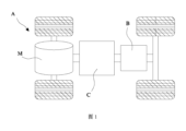
図1は、本出願による電力消費装置の具体的な実施例における構造概略図である。 FIG. 1 is a structural schematic diagram of a specific embodiment of a power consumption device according to the present application.
図1に示すように、本出願の実施例は電池B、及び該電池Bを電源として使用する電力消費装置を提供する。電池Bを電源として使用する電力消費装置は車両A、船舶、小型飛行機等の機器を含み、該装置は電池Bを採用して電気エネルギーを供給し、該装置を駆動する駆動力を生成する。該装置は電力と他のタイプのエネルギー(例えば、化石エネルギー)とを同時に使用し、共に駆動力を生成してもよい。電池Bを電源として使用することができる装置であれば、いずれも本出願の保護範囲に属する。 As shown in FIG. 1, embodiments of the present application provide a battery B and a power consuming device that uses the battery B as a power source. Power consuming devices that use battery B as a power source include equipment such as vehicles A, ships, small airplanes, etc., which devices employ battery B to supply electrical energy and generate driving force to drive the devices. The device may simultaneously use electrical power and other types of energy (eg, fossil energy) to jointly generate motive power. Any device that can use battery B as a power source falls within the protection scope of the present application.
図1に示すように、電力消費装置は、車両Aを例として、本出願の実施例における車両Aは新エネルギー自動車であってもよく、該新エネルギー自動車は純電気自動車であってもよく、ハイブリッド自動車又はレンジエクステンダー自動車等であってもよい。車両Aの内部には、電池Bが設置されており、電池Bは、車両Aの底部又は頭部又は後部に設置されてもよい。電池Bは、車両Aへの給電に使用されることができ、例えば、電池Bは、車両Aの操作電源とすることができる。車両Aは、コントローラCと、モータMとをさらに含んでもよく、コントローラCは、電池BがモータMに給電し、例えば、車両Aの始動、ナビゲーション及び走行時の動作電力需要に用いるように制御するためのものである。 As shown in FIG. 1, the power consumption device takes vehicle A as an example, vehicle A in the embodiment of the present application may be a new energy vehicle, and the new energy vehicle may be a pure electric vehicle, It may be a hybrid vehicle, a range extender vehicle, or the like. A battery B is installed inside the vehicle A, and the battery B may be installed at the bottom, head, or rear of the vehicle A. Battery B can be used to power vehicle A; for example, battery B can be used as an operating power source for vehicle A. Vehicle A may further include a controller C and a motor M, the controller C controlling the battery B to power the motor M for use, for example, in starting, navigation and driving operating power needs of the vehicle A. It is for the purpose of
本出願のいくつかの実施例では、電池Bは、車両Aの操作電源として用いることができるだけでなく、車両Aの駆動電源として、ガソリン又は天然ガスの代わりに、又はその一部の代わりに車両Aに駆動動力を提供することもできる。 In some embodiments of the present application, battery B can be used not only as an operating power source for vehicle A, but also as a driving power source for vehicle A, instead of gasoline or natural gas, or in place of a portion thereof. It is also possible to provide driving power to A.
図2は、本出願のいくつかの実施例の電池Bの構造概略図である。 FIG. 2 is a structural schematic diagram of battery B in some embodiments of the present application.
図2に示すように、本出願のいくつかの実施例の電池Bは少なくとも二つの電池セル100を含み、ここで二つの電池セル100の電極端子11が溶接接続される。電池セル100の電極端子11は正極端子及び負極端子を含み、正極端子及び負極端子はそれぞれ電池セル100の長手方向Xの両端に設置される。
As shown in FIG. 2, the battery B of some embodiments of the present application includes at least two
二つの電池セル100を溶接接続して電池Bを構成する時、二つの電池セル100の正極端子を対向して設置し、且つ溶接接続することによって、二つの電池セル100を並列接続することができ、又は、二つの電池セル100の負極端子を対向して設置し、且つ溶接接続することによって、二つの電池セル100を並列接続し、そのうちの一つの電池セル100の正極端子と他の電池セル100の負極端子を対向して設置し、且つ溶接接続することによって、二つの電池セル100を直列接続する。
When constructing battery B by connecting two
いくつかの実施例において、異なる電力使用需要を満たすために、電池Bは複数の電池セル100を含んでもよい。任意選択的に、まず二つの電池セル100の電極端子11を溶接接続し、次に、二つずつ溶接接続された電池セル100を並列又は直列又は直並列に接続して電池Bを形成することができ、直並列に接続されるとは、直列接続と並列接続の混合を意味する。まず、二つの電池セル100の電極端子11を溶接接続し、次に、別の電池セル100のうちの一つの電極端子11を溶接接続された二つの電池セル100のうちの一つの電池セル100の端部の電極端子11に溶接接続することによって、三つの電池セル100が一本の直線に沿って溶接接続された電池Bを形成してもよく、又は、これに基づき類推し、複数の電池セル100を一本の直線に沿って溶接接続し、電池Bを形成する。
In some embodiments, battery B may include
図3は本出願のいくつかの実施例の電池セル100の構造概略図である。
FIG. 3 is a structural schematic diagram of a
図3に示すように、電池セル100はエンドキャップアセンブリ1、ケース2、ケース2内に設置される電極アセンブリ、及び電池セル100内に注入された電解液(以下の各実施例の図面において、本出願の発明の要旨を明確に示すために、図において電極アセンブリ及び電解液を表示しない)を含む。エンドキャップアセンブリ1はケース2に接続され、電極アセンブリをケース2内に密閉する。エンドキャップアセンブリ1はエンドキャップ12及びエンドキャップ12に設置された電極端子11を含み、電極アセンブリは電極端子11に電気的に接続される。エンドキャップ12はケース2の開口にカバーされ、それによって電極アセンブリ及び電解液に密閉空間を提供する。ケース2は、様々な形状、例えば、円柱体、長方体などであってもよい。ケース2の形状は、電極アセンブリの具体的な形状に基づいて確定することができる。例えば、電極アセンブリが円柱体構造であれば、ケース2は円柱体構造を選択してもよく、電極アセンブリが長方体構造であれば、ケース2は長方体構造を選択してもよい。理解できるように、ケース2の形状と電極アセンブリの形状は異なってもよい。
As shown in FIG. 3, the
例示的には、図3において、ケース2は両端が開口した円柱体構造であり、両端の開口にそれぞれエンドキャップアセンブリ1がカバーされ、両側のエンドキャップアセンブリ1にいずれも電極端子11が設けられており、かつ両側の電極端子11の極性が逆である。ケース2の材質は、種々のものが可能であり、例えば、プラスチック、銅、鉄、アルミニウム、ステンレススチール、アルミニウム合金などであってもよく、本出願の実施例ではこれについて特に限定しない。
For example, in FIG. 3, the
電池セル100を組み立てる時、まず電極アセンブリをケース2内に置き、次に電極アセンブリと電極端子11を電気的に接続し固定した後、両側のエンドキャップ12をケース2に固定接続し、電池セル100の組み立てを完了する。組み立てを完了した後、電池セル100の内部に電解液を注入する。
When assembling the
一つの具体的な実施例において、本出願は電池を提供し、該電池は、少なくとも二つの電池セル100を含み、電池セル100は電池セル100の長手方向Xの両側の端部に設置された電極端子11を含み、電池セル100の一方側の電極端子11に電池セルの長手方向Xに沿って電解液を注入するための注液孔111が設けられており、二つの電池セル100の注液孔111が設けられている電極端子11は長手方向Xに沿って対向して設置され、且つ溶接接続されることによって、前記注液孔111をシールする。
In one specific embodiment, the present application provides a battery, the battery includes at least two
図4は図3の電池セル100の上面図であり、図5は図4における一つの実施例のE-E断面図である。
4 is a top view of the
図4及び図5に示すように、電極端子11はエンドキャップ12に設置され、電極端子11に注液孔111が設けられている。注液孔111は電極端子11を貫通する貫通孔であり、電池セル100の組み立てを完了した後、注液孔111を介して電池セル100の内部に電解液を注入する。
As shown in FIGS. 4 and 5, the
注液孔111を電極端子11に設置し、注液孔111はエンドキャップ12の空間を占有せず、それによって、電極端子11のサイズを大きくし、電極端子11の電流通過面積を増加させることができる。
The
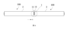
図6は、本出願の一つの実施例の電池Bの断面図である。 FIG. 6 is a cross-sectional view of battery B according to one embodiment of the present application.
図6に示すように、注液孔111を介して電池セル100内に一定量の電解液を注入した後、二つの電池セル100の注液孔111が設けられている電極端子11は電池セルの長手方向Xに沿って対向して設置され、且つ溶接接続され、電池Bを形成する。
As shown in FIG. 6, after a certain amount of electrolyte is injected into the
本実施例において、二つの電池セル100の注液孔111が設けられている電極端子11の極性は同じであり、この二つの電極端子11を対向して設置し、且つ溶接接続した後、二つの電池セル100を並列接続し、電池Bを形成する。二つの対向して溶接された電極端子11の極性が逆となるように設置することによって、二つの電池セル100を直列接続し、電池Bを形成してもよい。
In this embodiment, the polarities of the
注液孔111は電池セル100に対する注液を完了した後、注液孔111をシールする必要があり、それによって電池セル100全体のシール性を保証する。従来技術では、注液孔111のシールを実現するために、注液工程を完了した後、注液孔111内にシール釘を取り付け、レーザ溶接によりシール釘を注液孔111内に溶接し、注液孔111のシールを実現する必要がある。シール釘の溶接を行う前に、シール釘を注液孔111内に入れるが電池セル100の内部に落ちないように、注液孔111の内部に段差構造をさらに設置する必要があり、シール釘の位置決めを実現する。シール釘による注液孔111に対するシール方式について、注液孔111の加工が複雑であるだけでなく、シール釘を固定する工程を増加させる。
The
本出願の実施例において、注液孔111を電極端子11に設置し、注液孔111が設けられている二つの電極端子11を対向して設置し、且つ溶接接続し、追加のシール工程を行う必要がなく、電極端子11自体により電池Bの全体的なシールを直接的に実現し、生産効率を提供し、コストを低減させる。かつ、二つの電池セル100の注液孔111が設けられている電極端子11を溶接接続するため、シール釘で溶接しシールする必要がないため、注液孔111内に段差構造を加工してシール釘を置く必要がなく、それによって注液孔111の加工量を減少させる。かつ、シール釘のレーザ溶接工程を取り消し、注液孔111の断面形状も円形の制限を受けず、様々な状況に適用される様々な形状、例えば方形、多角形又は不規則な形状等であってもよく、無論、円形も排除しない。注液孔111の構造形式に多様な選択を提供し、注液孔の形状に対する加工要件も低減し、円形の注液孔に厳密に加工する必要がない。
In the embodiment of the present application, the
図7は、図6におけるI部の拡大図である。 FIG. 7 is an enlarged view of section I in FIG. 6.
図7に示すように、いくつかの実施例において、注液孔111が電極端子11の中心位置に位置することによって、二つの電池セル100の注液孔111の連通設置を容易にする。
As shown in FIG. 7, in some embodiments, the
電極端子11の中心位置に注液孔111を設置すれば、電極端子11の溶接による注液孔111への影響を回避することができ、二つの電極端子11が突き合わせる時、二つの注液孔111の間の連通を容易にすることもでき、それによって、二つの電池セル100の間の電解液は相補的でかつバランスをとれる。
If the
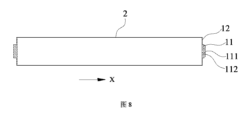
図8は、図4における別の実施例のE-E断面図である。 FIG. 8 is a sectional view taken along line EE of another embodiment in FIG.
図8に示すように、別の実施例において、電池セル100の電極端子11がエンドキャップ12に設置され、電極端子11に注液孔111が設けられている。注液孔111は、電極端子11を貫通する貫通孔である。電極端子11の注液孔111が設けられている側面に溝112がさらに設けられており、電池セルの長手方向Xに垂直な方向に沿って、溝112のサイズは注液孔111のサイズより大きい。
As shown in FIG. 8, in another embodiment, an
図9は、本出願の別の実施例の電池Bの断面図であり、図10は、図9におけるII部の拡大図である。 FIG. 9 is a sectional view of a battery B according to another embodiment of the present application, and FIG. 10 is an enlarged view of section II in FIG. 9.
図9及び図10に示すように、注液孔111を介して電池セル100内に一定量の電解液を注入した後、二つの電池セル100の注液孔111が設けられている電極端子11は電池セルの長手方向Xに沿って対向して設置され、且つ溶接接続され、電池Bを形成する。
As shown in FIGS. 9 and 10, after injecting a certain amount of electrolyte into the
二つの電池セル100の電極端子11を溶接する時、電池セル100を水平に置く必要がある。注液孔111をシールしていないため、電池セル100内の電解液は、電池セル100が水平に置かれる時、注液孔111から流出するリスクがある。
When welding the
図10に示すように、注液孔111の内側面に溝112を設置し、電池セル100が水平に置かれた後、電解液が電池セル100内から流出する時、まず溝112内に蓄積される。注液孔111が設けられている二つの電極端子11を溶接する時、溝112の電解液に対する緩衝作用のため、溶接過程で、電解液が注液孔111から流出するリスクを減少させ、かつ電解液の流出による溶接継ぎ目の品質への影響を回避する。
As shown in FIG. 10, a
図11は、図4における別の実施例のE-E断面図であり、図12は、図11における一つの実施例のIII部の拡大図である。 11 is a sectional view taken along the line EE of another embodiment in FIG. 4, and FIG. 12 is an enlarged view of section III of one embodiment in FIG.
図11及び図12に示すように、他のいくつかの実施例において、注液孔111は電極端子11の中心位置からずれて設置されることによって、二つの電池セル100の注液孔111がずれて設置される。
As shown in FIGS. 11 and 12, in some other embodiments, the
図12に示すように、注液孔111の中心線F2が電極端子11の中心線F1から離れる距離はLである。一つの具体的な実施例において、距離Lは注液孔111の内面から注液孔111の中心線F2までの最大距離Rより大きい。
As shown in FIG. 12, the distance between the center line F2 of the
図13は本出願の別の実施例の電池Bの断面図であり、図14は図13における一つの実施例のIV部の拡大図である。 FIG. 13 is a sectional view of battery B according to another embodiment of the present application, and FIG. 14 is an enlarged view of section IV of one embodiment in FIG.
図13及び図14に示すように、本実施例において、注液孔111を介して電池セル100内に一定量の電解液を注入した後、二つの電池セル100の注液孔111が設けられている電極端子11は電池セルの長手方向Xに沿って対向して設置され、且つ溶接接続され、電池Bを形成する。二つの電極端子11を対向して設置する時、二つの注液孔111をずらして設置し、すなわち二つの注液孔111は電池セルの長手方向Xに沿って一本の直線に位置しない。
As shown in FIGS. 13 and 14, in this embodiment, after a certain amount of electrolyte is injected into the
図14に示すように、二つの電池セル100の注液孔111がずれて設置され、注液孔111の中心線F2が電極端子11の中心線F1からずれた距離Lは、注液孔111の最大距離Rより大きく、この時、二つの注液孔111をずらして設置する時、二つの注液孔111を完全にずらして連通させず、二つの電極端子11を溶接接続した後、そのうちの一つの注液孔111は別の電極端子11の注液孔111が設置されていない部分により閉塞することができ、二つの電池セル100内の電解液が使用過程で相互に流通することを回避する。
As shown in FIG. 14, the liquid injection holes 111 of the two
図14に示された二つの電池セル100の注液孔111がずれた角度は180度であり、即ち、二つの注液孔111の中心線と電極端子11の中心線は同一の平面に位置する。本出願は、ずれた角度が180度であることに限定されず、二つの電極端子11を対向して設置する時、二つの注液孔111が完全にずれ、連通していないことを保証すればよく、それによって、二つの電池セル100内の電解液が相互に流通しないことを実現することができる。突き合わせられた二つの電極端子11が、電極が逆である二つの電極である時、流通しない注液孔111の設計を採用することは有利である。
The angle at which the liquid injection holes 111 of the two
図15は、図11における別の実施例のIII部の拡大図である。 FIG. 15 is an enlarged view of part III of another embodiment in FIG.
図15に示すように、他の実施例において、電極端子11の電池セルの長手方向Xに沿った端部の外周に段差部113が設けられている。段差部113は電極端子11の端部に沿って環状に設置されることによって、電極端子11の端部の外周に一部の切り欠きが形成される。図15における段差部113は環状に設置された斜面面取りであり、段差部113の断面形状は切り欠きを形成できる他の形状であってもよく、例えば方形、台形、円弧状などである。
As shown in FIG. 15, in another embodiment, a stepped
図16は、図15における二つの電池セル100の溶接接続の部分拡大断面図である。
FIG. 16 is a partially enlarged sectional view of the welded connection of the two
図16に示すように、本実施例の二つの電池セル100の電極端子11が対向して設置されて溶接接続される時、電極端子11の端部の段差部113が一部の切り欠きを形成し、二つの段差部113が対向して設置された後、二つの切り欠きが対応した後、溶接溝114を形成する。
As shown in FIG. 16, when the
溶接溝114の位置で二つの電極端子11を溶接接続し、溶接する時、溶接レーザの反射が溶接溝114内に集中し、溶接品質を向上させ、レーザ溶接による電池エンドキャップへの影響を低減させ、電池Bのシール性を強化し、かつ電池の完成品の歩留まりを向上させる。
When two
いくつかの実施例において、注液孔111の断面は円形、方形、三角形又は多角形である。従来の注液孔111はシール釘でシールされる時、レーザ溶接を行う必要があるが、レーザ溶接の軌跡制限のため、注液孔111は円形にすることしかできない。本出願では、注液孔111を電極端子11に設置し、二つの電池セル100の電極端子11を溶接接続するため、注液孔111に対して追加のシール釘で溶接してシールする必要がないため、注液孔111を方形、三角形又は多角形等の他の形状にすることができ、レーザ溶接の軌跡制限を受けず、円形に限定されるものではなく、注液孔111の形状をより柔軟に設置する。
In some embodiments, the cross section of the
以上の各実施例は、二つの電池セル100を対向して設置し、且つ溶接接続することを説明したが、複数の電池セル100を一体に溶接接続することもできる。以下の実施例は、三つの電池セル100を溶接接続することを例として説明する。
In each of the above embodiments, two
図17は、本出願の更なる別の実施例の電池Bの断面図である。 FIG. 17 is a cross-sectional view of a battery B according to yet another embodiment of the present application.
図17に示すように、三つの電池セル100は一体に溶接接続され、電池Bを形成する。ここで、二つの電池セル100の注液孔111が設けられている電極端子11は対向して設置され、かつ溶接接続され、それによってこの二つの電池セル100が並列に接続され、この二つの電池セル100の電極端子11の溶接接続方式は図7に示される実施例の接続方式と同じである。該注液孔111の構造形式は、図10又は図14の構造形式と同じであってもよく、又は異なる構造形式の組み合わせであってもよい。
As shown in FIG. 17, three
図18は、図17におけるV部の拡大図である。 FIG. 18 is an enlarged view of the V section in FIG. 17.
図18に示すように、注液孔111が設けられている別の電池セル100の電極端子は二つの溶接接続された電池セル100のうちの一つの電池セル100の端部の注液孔111が設置されていない電極端子11に溶接接続され、注液孔111が設置されていない電極端子11は注液孔が設置された電極端子11の極性と逆であり、それによって、これらの二つの電池セル100を直列接続する。図18において、注液孔111が設置されていない電極端子11は実体構造であり、それに溶接接続された電極端子11の注液孔111をシールすることができる。
As shown in FIG. 18, the electrode terminal of another
本出願は、上記実施例の二つの電池セル100を溶接接続するか、又は三つの電池セル100を溶接接続して電池Bを形成することに限定されるものではなく、それは、複数の電池セル100を上記接続方式により一体に溶接接続し、複数の電池セル100を含む電池Bを形成してもよい。
The present application is not limited to welding together two
本出願の以上の各実施例において、電池セル100は円筒電池であってもよく、及び/又は電極端子は円筒形電極端子であってもよい。当然のことながら、本出願はこれに限定されるものではなく、他の形状の電池構造に適応することもできる。
In each of the above embodiments of the present application, the
また、本出願も上記各実施例の構造に限定されるものではなく、それは上記各実施例の組み合わせであってもよい。 Further, the present application is not limited to the structure of each of the above embodiments, and may be a combination of the above embodiments.
図19は、本出願の一つの実施例の電池の作製方法のフローチャートである。 FIG. 19 is a flowchart of a method for manufacturing a battery according to one embodiment of the present application.
本出願は、さらに電池の作製方法に関し、該電池Bは少なくとも二つの電池セル100を含み、電池セル100は電池セルの長手方向Xの両側の端部に設置された電極端子11を含む。
The present application further relates to a method for manufacturing a battery, in which the battery B includes at least two
図19に示すように、該電池の作製方法は以下のステップを含む。 As shown in FIG. 19, the method for manufacturing the battery includes the following steps.
ステップS1、電池セル100のうちの一方側の電極端子11に電池セルの長手方向Xに沿って電解液を注入するための注液孔111を設置する。
Step S1: A
ステップS2、注液孔111を介して電池セル100の内部に電解液を注入する。
Step S2: Inject the electrolyte into the
ステップS3、二つの電池セル100の注液孔111が設けられている電極端子11を電池セルの長手方向Xに沿って対向して設置し、且つ溶接接続する。
Step S3: The
本出願の電池の作製方法は、注液孔111を電極端子11に設置し、注液孔111はエンドキャップ12の空間を占有せず、それによって、電極端子11のサイズを大きくし、電極端子11の電流通過面積を増加させることができる。注液孔111が設けられている二つの電極端子11を対向して設置して溶接接続する。追加のシール工程を行う必要がなく、電極端子11自体により電池Bの全体的なシールを直接的に実現し、コストを低減させ、生産効率を向上させる。かつ、二つの電池セル100の注液孔111が設けられている電極端子11を溶接接続するため、シール釘で溶接しシールする必要がないため、注液孔111内に段差構造を加工してシール釘を置く必要がなく、それによって、注液孔の加工量を減少させる。
The method of manufacturing a battery of the present application includes installing a
いくつかの実施例において、電池の作製方法は電池に対して気密性を検出するステップをさらに含む。電池セル100の組み立てを完了し、かつ電解液の注入及びシールを完了した後、電池セル100のシール性を確保し、電池セル100の歩留まりを保証するために、気密性の検出を行う必要がある。
In some embodiments, the method of making a battery further includes detecting hermeticity for the battery. After completing the assembly of the
本出願の実施例の電池セル100の組み立てを完了し、電解液を注入した後、電池セル100に対して追加のシールを行わず、電池セル100の注液孔111が設置された電極端子11を対向して設置し、且つ溶接接続することによって、電池Bを形成し、それによって、電池Bの全体的なシールを実現する。そのため、電池B全体に対して気密性の検出を行う必要がある。
After completing the assembly of the
本出願の電池Bに対して気密性の検出を行うために、二つの電池セル100の注液孔111が設けられている電極端子11を電池セルの長手方向Xに沿って対向して設置し、且つ溶接接続する前に、注液孔111を介して電池セル100の内部にヘリウムガスを注入するステップをさらに含む。
In order to detect the airtightness of the battery B of the present application, the
電池セル100内にヘリウムガスを注入してから、注液孔111が設けられている二つの電極端子11を溶接接続することによって、電池Bは全体的なシールを実現する。溶接を完了した後、電池B全体に対して気密性の検出を行い、電池Bからヘリウムガスが漏れるか否かを検出し、ヘリウムガスが漏れないと、電池B全体のシールが良好であると示す。
After helium gas is injected into the
本出願の電池の作製方法は、注液孔111を介して電池セル100の内部にヘリウムガスを注入し、二つの電池セル100の電極端子11をさらに溶接接続するため、気密性検出孔を追加的に開設して該検出孔をシールする必要がなく、電池作製工程を減少させ、生産効率を向上させる。
In the battery manufacturing method of the present application, helium gas is injected into the inside of the
本出願に係る電力消費装置は、上述した電池Bを使用し、又はその電池Bは上記電池の作製方法で作製される。 The power consumption device according to the present application uses the battery B described above, or the battery B is manufactured by the battery manufacturing method described above.
上記したのは、本出願の好適な実施例に過ぎず、本出願を制限するためのものではなく、当業者にとって、本出願は、種々な変更や変形が有り得る。本出願の精神及び原則内で行われる全ての修正、同等の置き換え、改善などは、いずれも本出願の保護範囲内に含まれるべきである。 The above description is only a preferred embodiment of the present application, and is not intended to limit the present application, and a person skilled in the art will notice various changes and modifications to the present application. All modifications, equivalent replacements, improvements, etc. made within the spirit and principles of this application shall be included within the protection scope of this application.
A-車両
B-電池
C-コントローラ
M-モータ
100-電池セル
1-エンドキャップアセンブリ
11-電極端子
111-注液孔
112-溝
113-段差部
114-溶接溝
12-エンドキャップ
2-ケース
A-Vehicle B-Battery C-Controller M-Motor 100-Battery cell 1-End cap assembly 11-Electrode terminal 111-Injection hole 112-Groove 113-Step 114-Welding groove 12-End cap 2-Case
Claims (12)
前記電池セルは前記電池セルの長手方向の両側の端部に設置された電極端子を含み、
一方側の前記電極端子に前記電池セルの長手方向に沿って電解液を注入するための注液孔が設けられており、
二つの前記電池セルの前記電極端子は、前記電池セルの長手方向に沿って対向して設置され、且つ溶接接続されることによって、前記注液孔をシールする、ことを特徴とする電池。 A battery, comprising at least two battery cells,
The battery cell includes electrode terminals installed at both longitudinal ends of the battery cell,
A liquid injection hole for injecting an electrolytic solution along the longitudinal direction of the battery cell is provided in the electrode terminal on one side,
A battery characterized in that the electrode terminals of the two battery cells are installed oppositely along the longitudinal direction of the battery cells and are welded and connected to seal the liquid injection hole.
そのうちの一方側の前記電極端子に前記電池セルの長手方向に沿って電解液を注入するための注液孔を設置するステップと、
前記注液孔を介して前記電池セルの内部に電解液を注入するステップと、
二つの前記電池セルの前記注液孔が設けられている前記電極端子を前記電池セルの長手方向に沿って対向して設置し、且つ溶接接続するステップとを含む、ことを特徴とする電池の作製方法。 A method for producing a battery comprising at least two battery cells each including electrode terminals installed at both ends of the battery cell in the longitudinal direction, the method comprising:
installing a liquid injection hole for injecting an electrolyte along the longitudinal direction of the battery cell in the electrode terminal on one side of the electrode terminal;
Injecting an electrolyte into the battery cell through the liquid injection hole;
A step of installing the electrode terminals provided with the liquid injection holes of the two battery cells so as to face each other along the longitudinal direction of the battery cells, and connecting them by welding. Fabrication method.
Applications Claiming Priority (1)
| Application Number | Priority Date | Filing Date | Title |
|---|---|---|---|
| PCT/CN2021/112642 WO2023019374A1 (en) | 2021-08-14 | 2021-08-14 | Battery, battery manufacturing method and electric apparatus |
Publications (2)
| Publication Number | Publication Date |
|---|---|
| JP2023543473A true JP2023543473A (en) | 2023-10-16 |
| JP7704847B2 JP7704847B2 (en) | 2025-07-08 |
Family
ID=85239333
Family Applications (1)
| Application Number | Title | Priority Date | Filing Date |
|---|---|---|---|
| JP2023519748A Active JP7704847B2 (en) | 2021-08-14 | 2021-08-14 | BATTERY, METHOD FOR MANUFACTURING BATTERY, AND POWER CONSUMPTION DEVICE |
Country Status (6)
| Country | Link |
|---|---|
| US (1) | US20230238674A1 (en) |
| EP (1) | EP4199219A4 (en) |
| JP (1) | JP7704847B2 (en) |
| KR (1) | KR102938785B1 (en) |
| CN (1) | CN116670879A (en) |
| WO (1) | WO2023019374A1 (en) |
Cited By (1)
| Publication number | Priority date | Publication date | Assignee | Title |
|---|---|---|---|---|
| JP2024125704A (en) * | 2023-03-06 | 2024-09-19 | プライムプラネットエナジー&ソリューションズ株式会社 | Sealed power storage device, its manufacturing method and its disassembly method, case-recycling sealed power storage device and its manufacturing method |
Citations (3)
| Publication number | Priority date | Publication date | Assignee | Title |
|---|---|---|---|---|
| JP2000149910A (en) * | 1998-11-04 | 2000-05-30 | Ngk Insulators Ltd | Lithium secondary battery |
| JP2014183026A (en) * | 2013-03-21 | 2014-09-29 | Toyota Motor Corp | Method of manufacturing sealed battery |
| CN112072017A (en) * | 2020-08-19 | 2020-12-11 | 江苏塔菲尔动力系统有限公司 | A battery module based on cell strings |
Family Cites Families (7)
| Publication number | Priority date | Publication date | Assignee | Title |
|---|---|---|---|---|
| JP2000200597A (en) * | 1999-01-05 | 2000-07-18 | Japan Storage Battery Co Ltd | Battery |
| DE10064648C2 (en) * | 1999-12-28 | 2003-09-18 | Honda Motor Co Ltd | battery unit |
| DE102006005532B4 (en) * | 2006-02-07 | 2009-09-24 | Epcos Ag | Connection element for an electric capacitor, capacitor and capacitor connection |
| CN204834764U (en) * | 2015-06-17 | 2015-12-02 | 深圳市沃特玛电池有限公司 | Cylindrical high magnification lithium ion battery of edge weld |
| CN208284552U (en) * | 2018-06-01 | 2018-12-25 | 苏州安靠电源有限公司 | The uniform end face weld battery of fluid injection |
| CN110518174B (en) * | 2019-10-23 | 2020-03-20 | 比亚迪股份有限公司 | Battery, battery module, battery pack and electric vehicle |
| CN112993473B (en) * | 2019-11-29 | 2023-09-05 | 比亚迪股份有限公司 | A battery, a battery module, a battery pack and an electric vehicle |
-
2021
- 2021-08-14 JP JP2023519748A patent/JP7704847B2/en active Active
- 2021-08-14 KR KR1020237011272A patent/KR102938785B1/en active Active
- 2021-08-14 EP EP21953632.3A patent/EP4199219A4/en active Pending
- 2021-08-14 WO PCT/CN2021/112642 patent/WO2023019374A1/en not_active Ceased
- 2021-08-14 CN CN202180085491.2A patent/CN116670879A/en active Pending
-
2023
- 2023-03-10 US US18/120,239 patent/US20230238674A1/en active Pending
Patent Citations (3)
| Publication number | Priority date | Publication date | Assignee | Title |
|---|---|---|---|---|
| JP2000149910A (en) * | 1998-11-04 | 2000-05-30 | Ngk Insulators Ltd | Lithium secondary battery |
| JP2014183026A (en) * | 2013-03-21 | 2014-09-29 | Toyota Motor Corp | Method of manufacturing sealed battery |
| CN112072017A (en) * | 2020-08-19 | 2020-12-11 | 江苏塔菲尔动力系统有限公司 | A battery module based on cell strings |
Cited By (2)
| Publication number | Priority date | Publication date | Assignee | Title |
|---|---|---|---|---|
| JP2024125704A (en) * | 2023-03-06 | 2024-09-19 | プライムプラネットエナジー&ソリューションズ株式会社 | Sealed power storage device, its manufacturing method and its disassembly method, case-recycling sealed power storage device and its manufacturing method |
| JP7741835B2 (en) | 2023-03-06 | 2025-09-18 | プライムプラネットエナジー&ソリューションズ株式会社 | Sealed electricity storage device, its manufacturing method and disassembly method |
Also Published As
| Publication number | Publication date |
|---|---|
| JP7704847B2 (en) | 2025-07-08 |
| CN116670879A (en) | 2023-08-29 |
| EP4199219A1 (en) | 2023-06-21 |
| WO2023019374A1 (en) | 2023-02-23 |
| EP4199219A4 (en) | 2024-07-24 |
| KR102938785B1 (en) | 2026-03-12 |
| US20230238674A1 (en) | 2023-07-27 |
| KR20230061487A (en) | 2023-05-08 |
Similar Documents
| Publication | Publication Date | Title |
|---|---|---|
| US12597682B2 (en) | Battery cell, battery, and electric apparatus | |
| EP2378593B1 (en) | Battery module | |
| US12074345B2 (en) | Terminal, secondary battery provided with same, and methods for producing same | |
| US8623540B2 (en) | Rechargeable battery and rechargeable battery module | |
| US9819002B2 (en) | Rechargeable battery and rechargeable battery module including the same | |
| JP4493623B2 (en) | Secondary battery | |
| CN217768704U (en) | Top cover assembly, cylindrical battery cell, battery and electrical device | |
| CN115347287B (en) | Battery top cover, battery and battery manufacturing method | |
| US20230048125A1 (en) | Battery cell, battery, electrical device, and manufacturing method and device for battery cell | |
| KR20100065670A (en) | Rechargeable battery | |
| KR20230042289A (en) | Battery cells, batteries, electric devices, methods and devices for manufacturing battery cells | |
| JP7704847B2 (en) | BATTERY, METHOD FOR MANUFACTURING BATTERY, AND POWER CONSUMPTION DEVICE | |
| CN115810842B (en) | Battery monomer and electric equipment | |
| US20250062503A1 (en) | Battery | |
| CN220138478U (en) | Top cap of battery and battery | |
| US20240380080A1 (en) | Battery cell, battery, electrical device, and method and device for manufacturing battery cell | |
| CN218070137U (en) | Battery core, battery module and electric automobile | |
| JP2008098012A (en) | Battery, battery manufacturing method, and vehicle equipped with the battery | |
| KR100649205B1 (en) | Secondary Battery and Its Cap Assembly | |
| CN217507419U (en) | Secondary battery and battery module | |
| KR102954715B1 (en) | Battery cells, batteries, and electrical devices | |
| KR102960852B1 (en) | Battery cell, battery, power supply device and method and device for manufacturing battery cell | |
| CN214153039U (en) | Solid-state battery structure | |
| KR102954266B1 (en) | Battery cell, battery, electrical equipment, method of manufacturing a battery cell and equipment for manufacturing a battery cell | |
| KR20240031419A (en) | Battery cells, batteries, electrical equipment, battery cell manufacturing method, and battery cell manufacturing equipment |
Legal Events
| Date | Code | Title | Description |
|---|---|---|---|
| A521 | Request for written amendment filed |
Free format text: JAPANESE INTERMEDIATE CODE: A523 Effective date: 20230329 |
|
| A621 | Written request for application examination |
Free format text: JAPANESE INTERMEDIATE CODE: A621 Effective date: 20230329 |
|
| RD02 | Notification of acceptance of power of attorney |
Free format text: JAPANESE INTERMEDIATE CODE: A7422 Effective date: 20230601 |
|
| RD04 | Notification of resignation of power of attorney |
Free format text: JAPANESE INTERMEDIATE CODE: A7424 Effective date: 20230707 |
|
| A977 | Report on retrieval |
Free format text: JAPANESE INTERMEDIATE CODE: A971007 Effective date: 20240426 |
|
| A131 | Notification of reasons for refusal |
Free format text: JAPANESE INTERMEDIATE CODE: A131 Effective date: 20240603 |
|
| A711 | Notification of change in applicant |
Free format text: JAPANESE INTERMEDIATE CODE: A711 Effective date: 20240815 |
|
| A521 | Request for written amendment filed |
Free format text: JAPANESE INTERMEDIATE CODE: A523 Effective date: 20240903 |
|
| A131 | Notification of reasons for refusal |
Free format text: JAPANESE INTERMEDIATE CODE: A131 Effective date: 20250107 |
|
| A521 | Request for written amendment filed |
Free format text: JAPANESE INTERMEDIATE CODE: A523 Effective date: 20250303 |
|
| TRDD | Decision of grant or rejection written | ||
| A01 | Written decision to grant a patent or to grant a registration (utility model) |
Free format text: JAPANESE INTERMEDIATE CODE: A01 Effective date: 20250617 |
|
| A61 | First payment of annual fees (during grant procedure) |
Free format text: JAPANESE INTERMEDIATE CODE: A61 Effective date: 20250626 |
|
| R150 | Certificate of patent or registration of utility model |
Ref document number: 7704847 Country of ref document: JP Free format text: JAPANESE INTERMEDIATE CODE: R150 |