JP2024007773A - Switching valve and refrigeration cycle system - Google Patents
Switching valve and refrigeration cycle system Download PDFInfo
- Publication number
- JP2024007773A JP2024007773A JP2022109083A JP2022109083A JP2024007773A JP 2024007773 A JP2024007773 A JP 2024007773A JP 2022109083 A JP2022109083 A JP 2022109083A JP 2022109083 A JP2022109083 A JP 2022109083A JP 2024007773 A JP2024007773 A JP 2024007773A
- Authority
- JP
- Japan
- Prior art keywords
- valve
- hole
- valve seat
- switching valve
- slide
- Prior art date
- Legal status (The legal status is an assumption and is not a legal conclusion. Google has not performed a legal analysis and makes no representation as to the accuracy of the status listed.)
- Granted
Links
Images




Classifications
-
- F—MECHANICAL ENGINEERING; LIGHTING; HEATING; WEAPONS; BLASTING
- F25—REFRIGERATION OR COOLING; COMBINED HEATING AND REFRIGERATION SYSTEMS; HEAT PUMP SYSTEMS; MANUFACTURE OR STORAGE OF ICE; LIQUEFACTION SOLIDIFICATION OF GASES
- F25B—REFRIGERATION MACHINES, PLANTS OR SYSTEMS; COMBINED HEATING AND REFRIGERATION SYSTEMS; HEAT PUMP SYSTEMS
- F25B41/00—Fluid-circulation arrangements
- F25B41/20—Disposition of valves, e.g. of on-off valves or flow control valves
-
- F—MECHANICAL ENGINEERING; LIGHTING; HEATING; WEAPONS; BLASTING
- F25—REFRIGERATION OR COOLING; COMBINED HEATING AND REFRIGERATION SYSTEMS; HEAT PUMP SYSTEMS; MANUFACTURE OR STORAGE OF ICE; LIQUEFACTION SOLIDIFICATION OF GASES
- F25B—REFRIGERATION MACHINES, PLANTS OR SYSTEMS; COMBINED HEATING AND REFRIGERATION SYSTEMS; HEAT PUMP SYSTEMS
- F25B41/00—Fluid-circulation arrangements
- F25B41/40—Fluid line arrangements
Landscapes
- Engineering & Computer Science (AREA)
- Physics & Mathematics (AREA)
- Mechanical Engineering (AREA)
- Thermal Sciences (AREA)
- General Engineering & Computer Science (AREA)
- Valve Housings (AREA)
- Multiple-Way Valves (AREA)
Abstract
Description
本発明は、空気調和機等の冷凍サイクルシステムに用いられ、冷媒の流路を切り換える切換弁及び冷凍サイクルシステムに関する。 The present invention relates to a switching valve that is used in a refrigeration cycle system such as an air conditioner and switches a refrigerant flow path, and a refrigeration cycle system.
従来、切換弁本体に対し、その内部におけるスライド弁をスライドさせるパイロット駆動部がブラケットを介して連結され、パイロット駆動部に接続されて主スライド弁の駆動流体を通す複数の細管を備える切換弁が開示されている(例えば特許文献1参照)。切換弁本体にパイロット駆動部を連結するブラケットの中には、一端側が切換弁本体に固定されて他端側でパイロット駆動部を保持した一対の保持板を有する板金加工タイプのものがあり、特許文献1に記載の切換弁でもこのタイプのブラケットが使われている。
Conventionally, a switching valve has a pilot drive section that slides a slide valve inside the switching valve main body, which is connected via a bracket, and has a plurality of thin tubes that are connected to the pilot drive section and pass the driving fluid for the main slide valve. It has been disclosed (for example, see Patent Document 1). Among the brackets that connect the pilot drive unit to the switching valve body, there is a sheet metal processing type that has a pair of retaining plates with one end fixed to the switching valve body and the other end holding the pilot drive unit. This type of bracket is also used in the switching valve described in
ここで、上述のような板金部品として形成されることが多いブラケットは変形し易く、外力に対する強度が低くなりがちであって改善の余地が見られる。また、このような形態の切換弁は部品点数が多く、大型化しがちであり、この点においても改善の余地が見られる。 Here, the brackets that are often formed as sheet metal parts as described above are easily deformed and tend to have low strength against external forces, so there is room for improvement. Further, the switching valve of this type has a large number of parts and tends to be large in size, and there is room for improvement in this respect as well.
本発明の目的は、外力に対する強度を向上させることができるとともにサイズを抑えることができる切換弁及び冷凍サイクルシステムを提供することである。 An object of the present invention is to provide a switching valve and a refrigeration cycle system that can improve strength against external forces and can be reduced in size.
本発明の切換弁は、主スライド弁を内蔵し、当該主スライド弁のスライドを受けて流路状態を切換える切換弁本体と、所定の駆動流体を用いて前記主スライド弁をスライドさせるパイロット駆動部と、前記パイロット駆動部に接続されて前記駆動流体を通す複数の細管と、を備え、前記パイロット駆動部が、副スライド弁を内蔵し、前記駆動流体の流路状態を切換えて前記主スライド弁をスライドさせるために、前記副スライド弁をスライドさせるパイロット本体と、前記複数の細管が接続され、一部分が前記切換弁本体に固定されるとともに他の部分が前記パイロット本体に進入して弁座が構成されるように固定された部位であって、前記複数の細管に繋がって当該複数の細管とともに前記駆動流体の流路を構成する複数の細管連通孔、及び、前記切換弁本体との固定部分から前記パイロット本体への進入部分にかけて貫通して前記駆動流体の流路を構成する弁座貫通孔が形成され、前記複数の細管連通孔及び前記弁座貫通孔のうちの一つの孔は前記弁座から外れて開口し、他の複数の孔が前記弁座に開口して前記副スライド弁によって開閉される弁座部材と、を備え、前記切換弁本体が、前記主スライド弁と、前記主スライド弁を収容し、外壁に前記パイロット駆動部の前記弁座部材が固定されるとともに、当該外壁に、前記弁座貫通孔と連通し、当該弁座貫通孔とともに前記駆動流体の流路を構成する本体貫通孔が形成された主ハウジングと、を備えたことを特徴とする。 The switching valve of the present invention includes a switching valve main body that incorporates a main slide valve and switches the flow path state in response to the slide of the main slide valve, and a pilot drive unit that slides the main slide valve using a predetermined driving fluid. and a plurality of thin tubes that are connected to the pilot drive section and allow the drive fluid to pass therethrough, and the pilot drive section has a built-in sub-slide valve and switches the flow path state of the drive fluid to control the main slide valve. In order to slide the auxiliary slide valve, the pilot body that slides the sub-slide valve is connected to the plurality of thin tubes, one part of which is fixed to the switching valve body, and the other part of which enters the pilot body so that the valve seat is A plurality of capillary communication holes that are connected to the plurality of capillary tubes and constitute a flow path for the driving fluid together with the plurality of capillary tubes, and a fixed portion that is fixed to the switching valve main body. A valve seat through hole is formed that penetrates from the entrance to the pilot main body and forms a flow path for the driving fluid, and one of the plurality of thin tube communication holes and the valve seat through hole is formed in the valve seat through hole. a valve seat member that opens out of the seat, has a plurality of other holes that open into the valve seat, and is opened and closed by the auxiliary slide valve; A slide valve is accommodated, the valve seat member of the pilot drive unit is fixed to an outer wall, and the outer wall communicates with the valve seat through hole, and forms a flow path for the driving fluid together with the valve seat through hole. A main housing having a main body through hole formed therein.
尚、ここにいう流路状態の切換えとは、ある流路を別の流路に変更するという流路の切換え、及び、一の流路を閉鎖したり開放したりするという流路の開閉切換え、を含む技術概念を意味している。 Note that the switching of the flow path state here refers to the switching of a flow path by changing one flow path to another flow path, and the switching of a flow path by closing or opening one flow path. It means a technical concept that includes .
この切換弁によれば、パイロット駆動部を構成する弁座部材が直に切換弁本体に固定されることから、板金加工のブラケットを用いてパイロット駆動部を切換弁本体に連結する場合に比べて、外力に対する強度を向上させることができる。また、ブラケットが不要であることから部品点数が抑えられ、その分、切換弁のサイズを抑えることができる。 According to this switching valve, the valve seat member that makes up the pilot drive section is directly fixed to the switching valve body, which makes it easier to connect the pilot drive section to the switching valve body using a sheet metal bracket. , the strength against external forces can be improved. Furthermore, since no bracket is required, the number of parts can be reduced, and the size of the switching valve can be reduced accordingly.
ここで、前記切換弁本体には、各々が前記主ハウジングの内部と連通する複数の継手管が連結されており、前記パイロット駆動部の前記弁座部材は、前記複数の継手管のうち相対的に高圧の流体を流す高圧継手管が連通した弁室と、前記本体貫通孔を介して前記弁座貫通孔が繋がるように前記主ハウジングの外壁に固定されていることが好適である。 Here, a plurality of joint pipes, each of which communicates with the inside of the main housing, are connected to the switching valve main body, and the valve seat member of the pilot drive section is connected to a relative one of the plurality of joint pipes. Preferably, the valve chamber is fixed to the outer wall of the main housing such that the valve chamber through which a high-pressure joint pipe through which high-pressure fluid flows is connected to the valve seat through-hole via the main body through-hole.
この構成によれば、切換弁本体の弁室とパイロット駆動部とを繋ぐ高圧の流体の流通路が、弁座部材における弁座貫通孔と切換弁本体における本体貫通孔によって構成される。これにより、弁室とパイロット駆動部とを高圧用の細管で繋ぐ場合に比べて、高圧の流体の流通路が最短に抑えられて強度を更に向上させることができるとともに、上記の高圧用の細管が不要となる分、切換弁のサイズを更に抑えることができる。 According to this configuration, the high-pressure fluid flow path connecting the valve chamber of the switching valve main body and the pilot drive section is constituted by the valve seat through hole in the valve seat member and the main body through hole in the switching valve main body. As a result, compared to the case where the valve chamber and the pilot drive part are connected with a high-pressure thin tube, the flow path for high-pressure fluid can be minimized and the strength can be further improved. Since this is no longer necessary, the size of the switching valve can be further reduced.
また、前記主ハウジングが、筒状に形成され、その軸線に沿って前記主スライド弁がスライドするように当該主スライド弁を収容し、前記パイロット本体が、前記副スライド弁と、筒状に形成され、その軸線に沿って前記副スライド弁がスライドするように当該副スライド弁を収容した副ハウジングと、を備え、前記パイロット駆動部は、前記切換弁本体に対し、前記主ハウジングの軸線と前記副ハウジングの軸線とが互いに沿って延びた配置で取り付けられていることが好適である。 Further, the main housing is formed in a cylindrical shape and accommodates the main slide valve so that the main slide valve slides along the axis of the main housing, and the pilot body and the sub slide valve are formed in a cylindrical shape. and a sub-housing that accommodates the sub-slide valve so that the sub-slide valve slides along the axis thereof, and the pilot drive section is configured to align the axis of the main housing and the sub-housing with respect to the switching valve main body. Preferably, the secondary housing is attached in such a way that the axes of the secondary housing extend along each other.
この構成によれば、切換弁本体の主ハウジングとパイロット駆動部の副ハウジングとが、各々の軸線が互いに沿って延びた配置で取り付けられる。この配置では、主ハウジングの軸線と副ハウジングの軸線とが互いに直交する配置と比較して、パイロット駆動部の重心が切換弁本体に近づくこととなり、その結果、2本の軸線に直交する方向について切換弁のサイズを更に抑えることができる。また、パイロット駆動部の重心が切換弁本体側に近づくため、外力に対する切換弁の強度を更に向上させることができる。 According to this configuration, the main housing of the switching valve main body and the sub-housing of the pilot drive unit are attached with their respective axes extending along each other. In this arrangement, compared to an arrangement in which the axis of the main housing and the axis of the auxiliary housing are orthogonal to each other, the center of gravity of the pilot drive section is closer to the switching valve body, and as a result, in the direction perpendicular to the two axes, The size of the switching valve can be further reduced. Furthermore, since the center of gravity of the pilot drive portion approaches the switching valve main body side, the strength of the switching valve against external forces can be further improved.
また、前記切換弁本体には、各々が前記主ハウジングの内部と連通する複数の継手管が、それぞれの軸線が一の平面に含まれる配置で連結されており、前記切換弁本体、前記パイロット駆動部、及び前記複数の継手管は、前記主スライド弁及び前記副スライド弁が、何れも、前記複数の継手管それぞれの軸線を含む平面の面内方向に沿ってスライドするように配置されていることが好適である。 Further, a plurality of joint pipes, each of which communicates with the inside of the main housing, are connected to the switching valve main body in such a manner that their respective axes are included in one plane, and the switching valve main body, the pilot drive and the plurality of joint pipes are arranged such that the main slide valve and the sub-slide valve both slide along an in-plane direction of a plane including an axis of each of the plurality of joint pipes. It is preferable that
この構成によれば、切換弁本体における主スライド弁及びパイロット駆動部における副スライド弁のスライド方向が、複数の継手管それぞれの軸線を含む平面の面内方向となっているので、当該平面の面外方向について切換弁が薄型化されることとなる。つまり、上記の構成によれば、切換弁のサイズを更に抑えることができる。 According to this configuration, the sliding direction of the main slide valve in the switching valve body and the auxiliary slide valve in the pilot drive section is in the plane of the plane including the axes of each of the plurality of joint pipes, so that The switching valve is made thinner in the outward direction. That is, according to the above configuration, the size of the switching valve can be further reduced.
また、前記弁座部材は、一端部が前記進入部分で他端部が前記固定部分の柱状の部材であり、その周面の一部が軸方向に延在する平坦面となっており、前記複数の細管が前記平坦面に接続されていることが好適である。 Further, the valve seat member is a columnar member having one end as the entry portion and the other end as the fixed portion, and a part of its peripheral surface is a flat surface extending in the axial direction, and Preferably, a plurality of capillaries are connected to the flat surface.
この構成によれば、複数の細管を弁座部材にろう付けによって接続する場合に、弁座部材における平坦面にリングろうを配置することができるので、ろう付けに関する作業性を向上させることができる。 According to this configuration, when connecting a plurality of thin tubes to the valve seat member by brazing, the ring solder can be placed on the flat surface of the valve seat member, so the workability regarding brazing can be improved. .
また、前記パイロット駆動部における前記パイロット本体が、前記副スライド弁を保持して所定のスライド軸線に沿ってスライド可能に設けられたプランジャーと、前記副スライド弁とともに前記プランジャーをスライド可能に収容したプランジャーチューブと、前記プランジャーチューブの外周に巻かれ、電流が供給されることにより前記プランジャーを前記スライド軸線に沿ってスライドさせるコイル部と、前記コイル部に前記電流を供給するリード線と前記コイル部とを接合する接合部と、を備えており、前記接合部は、前記コイル部から前記切換弁本体との干渉を回避するように設けられるとともに、当該接合部は、前記コイル部から前記スライド軸線に対する直交方向へと突出するように設けられ、前記コイル部は、前記接合部が設けられた第1部分と、当該第1部分を除く第2部分と、を有して構成され、前記スライド軸線から前記弁座部材における前記切換弁本体との固定端までの第1長さが、前記スライド軸線から前記接合部の突出端までの第2長さよりも短く、前記スライド軸線から前記コイル部における前記第2部分の外面までの第3長さよりも長いことが好適である。 Further, the pilot main body of the pilot drive section includes a plunger that is provided to hold the sub-slide valve and to be slidable along a predetermined slide axis, and to slidably accommodate the plunger together with the sub-slide valve. a plunger tube, a coil portion that is wound around the outer circumference of the plunger tube and slides the plunger along the slide axis when a current is supplied thereto, and a lead wire that supplies the current to the coil portion. and a joint part for joining the coil part, the joint part being provided to avoid interference from the coil part with the switching valve main body, and the joint part joining the coil part to the switching valve body. The coil portion is provided so as to protrude in a direction perpendicular to the slide axis, and the coil portion includes a first portion provided with the joint portion and a second portion excluding the first portion. , a first length from the slide axis to a fixed end of the valve seat member with the switching valve main body is shorter than a second length from the slide axis to the protruding end of the joint, and It is preferable that the length is longer than the third length of the coil portion up to the outer surface of the second portion.
この構成によれば、パイロット駆動部のスライド軸線に対する直交方向について、弁座部材の寸法が上記の第1長さの規定によって必要最小限に最適化されることで、パイロット駆動部の重心が切換弁本体側に近づけられる。これにより、外力に対する切換弁の強度を更に向上させることができるとともに切換弁のサイズを更に抑えることができる。 According to this configuration, in the direction orthogonal to the slide axis of the pilot drive unit, the dimensions of the valve seat member are optimized to the necessary minimum according to the above-mentioned first length regulation, so that the center of gravity of the pilot drive unit can be switched. It can be brought closer to the valve body side. Thereby, the strength of the switching valve against external forces can be further improved, and the size of the switching valve can be further reduced.
また、前記弁座部材は、一端部が前記進入部分で他端部が前記固定部分の柱状の部材であって、前記パイロット本体と前記切換弁本体の相互間に位置し、前記固定部分で前記切換弁本体に固定されて前記パイロット本体を支える支柱部分が前記進入部分よりも太く、当該支柱部分と前記進入部分の境界に段差部が形成されており、前記進入部分は、前記段差部が前記パイロット本体の外周面に接するように係合した状態で前記パイロット本体に固定されていることが好適である。 The valve seat member is a columnar member having one end of the entry portion and the other end of the fixed portion, and is located between the pilot main body and the switching valve main body, and is located between the pilot main body and the switching valve main body, and the fixed portion A strut portion that is fixed to the switching valve body and supports the pilot body is thicker than the entry portion, and a stepped portion is formed at the boundary between the strut portion and the entrance portion, and the stepped portion of the entry portion is thicker than the entry portion. It is preferable that it is fixed to the pilot body while being engaged with the outer peripheral surface of the pilot body.
この構成によれば、弁座部材においてパイロット本体を支える支柱部分が進入部分よりも太く剛性が高められていることから、外力に対する切換弁の強度を更に向上させることができる。また、段差部がパイロット本体の外周面に接するように係合することから、パイロット本体に弁座部材を固定するに当たって、パイロット本体に対する弁座部材の位置決めを良好な作業性の下で行うことができる。 According to this configuration, the strut portion that supports the pilot body in the valve seat member is thicker and more rigid than the entry portion, so that the strength of the switching valve against external forces can be further improved. In addition, since the stepped portion engages in contact with the outer peripheral surface of the pilot body, it is possible to position the valve seat member relative to the pilot body with good workability when fixing the valve seat member to the pilot body. can.
また、前記弁座部材は、中実体に前記複数の細管連通孔及び前記弁座貫通孔が開けられたものであることが好適である。 Further, it is preferable that the valve seat member has the plurality of thin tube communication holes and the valve seat through hole formed in a solid body.
この構成によれば、弁座部材が中実体で構成されて剛性が高められていることから、外力に対する切換弁の強度を更に向上させることができる。 According to this configuration, since the valve seat member is made of a solid body and has increased rigidity, the strength of the switching valve against external forces can be further improved.
また、前記弁座部材の前記固定部分には前記切換弁本体に面着して接合される弁座側接合平面が形成され、前記切換弁本体の前記主ハウジングにおける外壁には、前記固定部分を受け入れるとともに前記弁座側接合平面と面着する本体側接合平面が底面となった受入れ凹部が形成されており、前記固定部分は、当該固定部分において前記弁座側接合平面を囲む外周面の一部が、前記受入れ凹部の内周面の一部に接するように係合した状態で前記主ハウジングの外壁に固定されていることが好適である。 Further, the fixed portion of the valve seat member is formed with a valve seat side joining plane that is joined to the switching valve main body in a face-to-face manner, and the fixed portion is formed on the outer wall of the main housing of the switching valve main body. A receiving recess is formed in which the bottom surface is a body-side joint plane that is received and faces the valve-seat-side joint plane, and the fixed part has a part of the outer circumferential surface surrounding the valve-seat-side joint plane in the fixed part. It is preferable that the receiving recess is fixed to the outer wall of the main housing while being engaged with a part of the inner circumferential surface of the receiving recess.
この構成によれば、弁座部材を切換弁本体にろう付けによって接続する場合に、弁座側接合平面と本体側接合平面とを面着させて安定した状態でろう付けを行うことができる。また、弁座部材における固定部分が主ハウジングにおける受入れ凹部に係合した状態で固定されるので、外力に対する切換弁の強度を更に向上させることができる。 According to this configuration, when the valve seat member is connected to the switching valve main body by brazing, the valve seat side joining plane and the main body side joining plane can be brought into contact with each other and brazing can be performed in a stable state. Furthermore, since the fixed portion of the valve seat member is fixed while being engaged with the receiving recess in the main housing, the strength of the switching valve against external forces can be further improved.
また、前記弁座部材における前記弁座貫通孔には、前記進入部分側の第1孔部と、前記固定部分側で前記第1孔部よりも大径の第2孔部と、前記第1孔部及び前記第2孔部の境界にあって両者を接続する段差部と、が設けられ、前記主ハウジングにおける前記本体貫通孔が、前記弁座貫通孔における前記第2孔部よりも小径の孔であって、前記第2孔部に収められて前記弁座貫通孔を流れる前記駆動流体から異物を除去するフィルターを更に備え、前記段差部が、前記第2孔部の内部における前記第1孔部側への前記フィルターの移動を規制し、前記主ハウジングの外壁における前記本体貫通孔の周縁部が、前記第2孔部の内部における前記本体貫通孔側への前記フィルターの移動を規制することが好適である。 Further, the valve seat through hole in the valve seat member includes a first hole portion on the entry portion side, a second hole portion having a larger diameter than the first hole portion on the fixed portion side, and the first hole portion on the fixed portion side. A stepped portion is provided at a boundary between the hole portion and the second hole portion and connects the two, and the main body through hole in the main housing has a smaller diameter than the second hole portion in the valve seat through hole. The hole further includes a filter that is housed in the second hole and removes foreign matter from the driving fluid flowing through the valve seat through hole, and the stepped portion is arranged so that the first hole inside the second hole has a filter. The movement of the filter toward the hole is restricted, and the peripheral edge of the main body through-hole in the outer wall of the main housing restricts the movement of the filter toward the main body through-hole inside the second hole. It is preferable that
この構成によれば、弁座貫通孔の内部に、駆動流体の流通方向の移動が規制された状態で異物除去用のフィルターが収められるので、駆動流体にフィルターが押し流されて脱落してしまう等といった事態を効果的に回避しつつ異物除去を行うことができる。また、フィルターが、スペースに余裕を設け易い弁座貫通孔の内部に収められるので、細管の内部に、細管の一部を拡管してフィルターを収める場合と比較して、切換弁におけるフィルター設置に関するサイズを抑えることができる。更に、弁座貫通孔の内部の段差構造や本体貫通孔の径との差異によるフィルターの移動規制によれば、例えば移動規制のために別部品のストッパを設ける場合に比べて部品点数を抑えてコストを低減することもできる。 According to this configuration, the filter for removing foreign matter is housed inside the valve seat through hole in a state where the movement of the driving fluid in the flow direction is restricted, so the filter may be swept away by the driving fluid and fall off. Foreign matter can be removed while effectively avoiding such situations. In addition, since the filter is housed inside the valve seat through-hole, which allows for easy space allowance, it is easier to install the filter in the switching valve, compared to the case where the filter is housed inside the thin tube by enlarging a part of the thin tube. Size can be reduced. Furthermore, by regulating the movement of the filter due to the step structure inside the valve seat through-hole or the difference in diameter from the main body through-hole, the number of parts can be reduced compared to, for example, providing a stopper as a separate part to restrict movement. Costs can also be reduced.
また、本発明の冷凍サイクルシステムは、流体である冷媒を圧縮する圧縮機と、冷却モード時に凝縮器として機能する第一熱交換器と、冷却モード時に蒸発器として機能する第二熱交換器と、前記第一熱交換器と前記第二熱交換器との間にて冷媒を膨張させて減圧する膨張手段と、上述の切換弁と、を備えたことを特徴とする。 Further, the refrigeration cycle system of the present invention includes a compressor that compresses a refrigerant that is a fluid, a first heat exchanger that functions as a condenser in the cooling mode, and a second heat exchanger that functions as an evaporator in the cooling mode. , characterized by comprising an expansion means for expanding and reducing the pressure of a refrigerant between the first heat exchanger and the second heat exchanger, and the above-mentioned switching valve.
この冷凍サイクルシステムによれば、上述の切換弁を備えたことから、この切換弁について外力に対する強度を向上させることができるとともにサイズを抑えることができる。 According to this refrigeration cycle system, since the above-mentioned switching valve is provided, the strength of the switching valve against external forces can be improved and the size can be reduced.
本発明の切換弁及び冷凍サイクルシステムによれば、外力に対する強度を向上させることができるとともにサイズを抑えることができる。 According to the switching valve and refrigeration cycle system of the present invention, the strength against external forces can be improved and the size can be reduced.
以下、一実施形態に係る切換弁及び冷凍サイクルシステムを図1~図10に基づいて説明する。 Hereinafter, a switching valve and a refrigeration cycle system according to one embodiment will be described based on FIGS. 1 to 10.
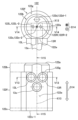
図1は、一実施形態の切換弁の全体構造を示す二面図である。また、図2は、図1に示されている切換弁を備える冷凍サイクルシステムを示す模式図である。 FIG. 1 is a two-sided view showing the overall structure of a switching valve according to an embodiment. Further, FIG. 2 is a schematic diagram showing a refrigeration cycle system including the switching valve shown in FIG. 1.
本実施形態の切換弁10は、詳細については後述するD継手管15d、E継手管15e、S継手管15s、C継手管15cという4つの継手管の連通状態を切換える四方切換弁である。この切換弁10は、これら4つの継手管の連通状態を切換えることで、図2に示されている冷凍サイクルシステム1における冷媒の流路を切換える。切換弁10は、切換弁本体11と、パイロット駆動部12と、第1ハウジング用細管13Lと、第2ハウジング用細管13Rと、低圧継手用細管13sと、を備えている。
The switching
切換弁本体11は、主ハウジング111の内部に主スライド弁112を内蔵し、当該主スライド弁112のスライドを受けて流路状態を切換える。本実施形態における流路状態の切換えとは、4つの継手管を介して構成される複数の流路において、一の流路を別の流路に変更するという流路の切換えを意味している。主ハウジング111は、両端が閉塞されたステンレス鋼製の円筒状の部材であって、その周壁に、ステンレス鋼製のD継手管15d、E継手管15e、S継手管15s、C継手管15cが、内部と連通するように連結されている。この主ハウジング111の内部には、主スライド弁112及び弁座113が設置されている。
The switching valve
主スライド弁112は、一対のピストン114L,114R、連結板115、及び弁体116を備えている。この主スライド弁112は、主ハウジング111の内部に設置されて上記の複数の継手管のうちの二対の継手管を連通するとともに、スライド移動することで連通対象の継手管を切換える。
The
一対のピストン114L,114Rは互いに対向配置され、パッキンを主ハウジング111の内周面に押圧しながら往復移動可能となっている。これにより、主ハウジング111の内部は、2つのピストン114L,114Rにより、中央部の高圧の主弁室11aと、主弁室11aの両側の第1作動室11bと第2作動室11cとに仕切られている。
The pair of
連結板115は金属板からなり、この連結板115は、主ハウジング111の主スライド軸線X11上に配置されるようにピストン114L,114Rの間に架設されるとともに、その中央に弁体116を保持している。そして、弁体116は、ピストン114L,114Rが移動すると連結板115に連動して弁座113上を摺動し、ピストン114L,114Rが主ハウジング111の左右の端部における所定のストッパ位置に達すると停止する。
The connecting
弁座113は主ハウジング111内の中間部に配設され、主ハウジング111の中間部の弁座113と対向する位置には、主ハウジング111内に開口する高圧配管としてのD継手管15dが取り付けられている。また、弁座113には、主ハウジング111の主スライド軸線X11方向に一直線上に並んで、一対の導管としてのE継手管15e及びC継手管15cと、低圧配管としてのS継手管15sが取り付けられている。弁体116にはその内側に椀状凹部116aが形成されている。そして、弁体116は、図1の左側の端部位置において、S継手管15sとE継手管15eとを椀状凹部116aにより連通する。このとき、C継手管15cは主弁室11aを介してD継手管15dに連通する。また、弁体116は、図1において主スライド弁112が右側に移動した右側の端部位置において、S継手管15sとC継手管15cとを椀状凹部116aにより連通する。このとき、E継手管15eは主弁室11aを介してD継手管15dに連通する。
The
図2に示されている冷凍サイクルシステム1において、D継手管15dは圧縮機1aの吐出口に接続される高圧配管となっており、S継手管15sは圧縮機1aの吸入口に接続される低圧配管となっている。C継手管15cは室外熱交換機1b(第一熱交換器)に接続される導管であり、E継手管15eは室内熱交換機1c(第二熱交換器)に接続される導管である。室外熱交換機1bと室内熱交換機1cは絞り装置1d(膨張手段)を介して接続される。C継手管15c、室外熱交換機1b、絞り装置1d、室内熱交換機1c、及びE継手管15eからなる流路と、S継手管15s、圧縮機1a、及びD継手管15dからなる流路とにより、冷凍サイクルシステム1が構成される。
In the
パイロット駆動部12は、主ハウジング111に接続されている。パイロット駆動部12は、主ハウジング111の内部において主軸方向D11に主スライド弁112を挟む一対の空間、即ち、第1作動室11b及び第2作動室11cの両方に駆動流体を流通させて、主スライド弁112を主軸方向D11にスライド移動させる。本実施形態では、このパイロット駆動部12が、第1作動室11b及び第2作動室11cの一方に高圧配管としてのD継手管15dの流体を流通させ、他方に低圧配管としてのS継手管15sの流体を流通させることで主スライド弁112をスライド移動させる。
The
このパイロット駆動部12と低圧配管としてのS継手管15sとの間が低圧継手用細管13sで繋がれ、パイロット駆動部12と第1作動室11bとの間が第1ハウジング用細管13Lで繋がれている。また、パイロット駆動部12と第2作動室11cとの間が第2ハウジング用細管13Rで繋がれている。低圧継手用細管13s、第1ハウジング用細管13L、及び第2ハウジング用細管13Rは、何れもステンレス鋼製の細管となっている。更に、詳細については後述するが、パイロット駆動部12と、高圧継手管であるD継手管15dが連通した主弁室11aとの間は、パイロット駆動部12におけるステンレス鋼製の弁座部材122で繋がれている。
The
パイロット駆動部12は、切換弁10と同様な構造を有する電磁弁であって、通電により内部の副スライド弁をスライド移動させて駆動流体の流路を切り換える。副スライド弁は、低圧配管としてのS継手管15sに連通する低圧継手用細管13sの連通先を、次のように切り替える。即ち、パイロット駆動部12は、低圧継手用細管13sの連通先を、切換弁10の第1作動室11bに接続された第1ハウジング用細管13Lと、第2作動室11cに接続された第2ハウジング用細管13Rとで切り換える。同時に、高圧の主弁室11aの連通先を第1ハウジング用細管13Lと第2ハウジング用細管13Rとで切り換える。これにより、第1作動室11bの圧力と第2作動室11cの圧力との間に圧力差を発生させ、当該圧力差により主スライド弁112を主軸方向D11に高圧側から低圧側へとスライド移動させる。そして、このスライド移動により、主スライド弁112における弁体116の位置が切り換えられて冷凍サイクルシステム1における冷媒の流路が切り換えられる。
The
以上の構成により、圧縮機1aで圧縮された高圧の冷媒はD継手管15dから主弁室11a内に流入し、冷房運転の状態(冷却モード時)では、高圧冷媒はC継手管15cから室外熱交換機1bに流入される。また、弁体116の位置を切り換えた暖房運転の状態(暖房モード時)では、高圧冷媒はE継手管15eから室内熱交換機1cに流入される。すなわち、冷房運転時には、圧縮機1aから吐出される冷媒はD継手管15d→C継手管15c→室外熱交換機1b→絞り装置1d→室内熱交換機1c→E継手管15eと循環する。この場合、室外熱交換機1bが凝縮器(コンデンサ)、室内熱交換機1cが蒸発器(エバポレータ)として機能し、冷房がなされる。絞り装置1dは、室外熱交換機1bと室内熱交換機1cとの間にて冷媒を膨張させて減圧する。また、暖房運転時には冷媒は逆に循環され、室内熱交換機1cが凝縮器、室外熱交換機1bが蒸発器として機能し、暖房がなされる。
With the above configuration, the high-pressure refrigerant compressed by the compressor 1a flows into the
ここで、本実施形態では、パイロット駆動部12が次のような構造を有している。
Here, in this embodiment, the
図3は、図1の切換弁におけるパイロット駆動部を、図1中のV11-V11線に沿った断面で示す断面図である。また、図4は、図3に示されているパイロット駆動部を、図3中のV12-V12線に沿った断面で示す断面図である。 FIG. 3 is a sectional view showing the pilot drive section of the switching valve of FIG. 1 along the line V11-V11 in FIG. Further, FIG. 4 is a sectional view showing the pilot drive section shown in FIG. 3 along the line V12-V12 in FIG.
パイロット駆動部12は、上述したように電磁弁であって、パイロット本体121と弁座部材122とを備えている。また、パイロット本体121が、副ハウジング121aと、副スライド弁121bと、プランジャー121cと、コイル部121dと、リード線R11の接合部121eと、を備えている。
The
パイロット本体121は、副スライド弁121bを内蔵し、駆動流体の流路状態を切換えて主スライド弁112をスライドさせるために、副スライド弁121bをスライドさせる。また、パイロット本体121では、第1ハウジング用細管13L、第2ハウジング用細管13R、及び低圧継手用細管13sの3本の細管と、弁座部材122における後述の弁座貫通孔122dを介して駆動流体の複数の流路が構成される。そして、パイロット本体121における流路状態の切換えとは、上記の複数の流路において、一の流路を別の流路に変更するという流路の切換えを意味している。
The pilot
このパイロット本体121の副ハウジング121aは、両端が閉塞されたステンレス鋼製の円筒状のハウジングであり、その内部に副スライド弁121b及びプランジャー121cを内蔵している。この副ハウジング121aの周壁が、プランジャー121cの移動を、副ハウジング121aの軸線と一致する副スライド軸線X12に沿った副軸方向D12のスライドに規制するプランジャーチューブ121a-1となっている。
The sub-housing 121a of the pilot
副スライド弁121bは、その内側に椀状凹部121b-1が形成されており、図3に示されている図3の左側の端部位置において、低圧継手用細管13sと第1ハウジング用細管13Lとを椀状凹部121b-1で連通する。このとき、第2ハウジング用細管13Rは、プランジャー121cに設けられた副弁室121c-1を介して切換弁本体11の高圧の主弁室11aに連通する。この副スライド弁121bが図3中の右方にスライドすると、低圧継手用細管13sの連通先が第2ハウジング用細管13Rへと切り替わり、第1ハウジング用細管13Lの連通先が高圧の主弁室11aへと切り替わる。
The
ここで、本実施形態では、副スライド弁121bの椀状凹部121b-1が半球状の凹部となっている。半球状とは異なり、例えば長円状の椀状凹部を設けたスライド弁では、椀状凹部の周縁の一部に直線部分が存在するが、スライド弁が周囲の駆動流体から圧力を受ける際に上記の直線部分に引張応力が掛かることとなる。スライド弁のサイズや駆動流体から受ける圧力の大きさ等によっては、直線部分に掛かる引張応力が過剰となる可能性がある。これに対し、本実施形態における半球状の椀状凹部121b-1を設けた副スライド弁121bによれば、上記のような引張応力が抑制されることから、副スライド弁121bの耐圧性を向上させることができる。更に、このような耐圧性の向上を見越して副スライド弁121bの肉厚を薄くすることが可能となり、その結果、副スライド弁121bの移動量も抑えることができる。
In this embodiment, the bowl-shaped
プランジャー121cは、略円柱状で、図3中の右方寄りの部分がマグネットとなっており、副軸方向D12に沿って延在する姿勢でプランジャーチューブ121a-1にスライド可能に収容されている。また、プランジャー121cは、プランジャーチューブ121a-1の内部で、副軸方向D12における弁座部材122側の一端部に副スライド弁121bを保持している。この一端部において、副スライド弁121bは、副スライド軸線X12と直交する副軸直交方向D13について弁座部材122に向かってバネ121c-2で付勢されている。また、プランジャー121cは、副軸方向D12について、弁座部材122と反対側から弁座部材122側へとバネ121c-3で付勢されている。この副軸方向D12の付勢により、副スライド弁121bは、低圧継手用細管13sと第1ハウジング用細管13Lとを連通する初期位置に位置付けられる。
The
コイル部121dは、プランジャーチューブ121a-1の外周に巻かれ、電流が供給されることによりプランジャー121cのマグネット部分に、当該マグネット部分と逆極性で引寄せ力を生じさせる磁力を付加する。このコイル部121dからの磁力は、プランジャー121cを、バネ121c-3の付勢に反して弁座部材122と反対側へと、副スライド軸線X12に沿って副軸方向D12にスライドさせる。このスライドにより、副スライド弁121bは、低圧継手用細管13sと第2ハウジング用細管13Rとを連通するスライド位置に位置付けられる。
The
接合部121eは、コイル部121dに電流を供給するリード線R11とコイル部121dとを接合する部位である。この接合部121eは、切換弁本体11との干渉を回避するように設けられるとともに、コイル部121dから副軸直交方向D13へと突出するように設けられている。
The joining
弁座部材122は、以上に説明した構造のパイロット本体121の内部で副スライド弁121bに摺擦される弁座122aを構成するとともに、このパイロット本体121を切換弁本体11に連結する部材となっている。また、この弁座部材122には、低圧継手用細管13s、第1ハウジング用細管13L、及び第2ハウジング用細管13Rの3本の細管が接続されている。
The
図5は、図3及び図4に断面図で示されている弁座部材を、弁座側から見た上面図と、細管の接続側から見た側面図と、で示す外観図である。また、図6は、図5中のV13-V13線に沿った断面図であり、図7は、図5中のV14-V14線に沿った断面図であり、図8は、図5中のV15-V15線に沿った断面図である。以下、図3及び図4とともに図5~図8も参照し、弁座部材122について説明する。
FIG. 5 is an external view of the valve seat member shown in cross-sectional view in FIGS. 3 and 4, including a top view viewed from the valve seat side and a side view viewed from the thin tube connection side. 6 is a sectional view taken along the line V13-V13 in FIG. 5, FIG. 7 is a sectional view taken along the line V14-V14 in FIG. 5, and FIG. 8 is a sectional view taken along the line V14-V14 in FIG. FIG. 3 is a sectional view taken along the line V15-V15. The
弁座部材122は、一部分が切換弁本体11に固定されるとともに他の部分がパイロット本体121に進入して弁座122aが構成されるように固定される。具体的には、この弁座部材122は、略円柱状の中実体であって、その一端部がパイロット本体121の内部に進入して弁座122aを構成する進入部分122bで、他端部が切換弁本体11に固定される固定部分122cとなっている。弁座122aは、進入部分122bの端面において副スライド弁121bによって摺擦される帯面状の範囲となっている。
A portion of the
また、弁座部材122の周面には、低圧継手用細管13s、第1ハウジング用細管13L、及び第2ハウジング用細管13Rが接続されている。そして、上記のように中実体の弁座部材122の内部に、低圧連通孔122s、第1ハウジング連通孔122L、及び第2ハウジング連通孔122Rという3つの細管連通孔が形成されている。
Furthermore, a low pressure joint
低圧連通孔122sは、低圧継手用細管13sに繋がって低圧継手用細管13sとともに低圧の駆動流体の流路を構成する。また、この低圧連通孔122sは、低圧直交孔122s-1と低圧軸線孔122s-2とで構成されている。低圧直交孔122s-1は、弁座部材122の中心軸である弁座軸線X13と直交する方向に開けられている。この低圧直交孔122s-1は、奥側が低圧継手用細管13sの内径と同径で、開口側が低圧継手用細管13sの外径よりも若干大径で開けられて低圧継手用細管13sが挿入される孔である。低圧軸線孔122s-2は、弁座軸線X13に沿って低圧直交孔122s-1よりも小径で開けられた孔であり、一端が低圧直交孔122s-1に繋がり、他端が弁座122aに開口している。
The low-
第1ハウジング連通孔122Lは、第1ハウジング用細管13Lに繋がって第1ハウジング用細管13Lとともに切換弁本体11の第1作動室11bへの駆動流体の流路を構成する。また、この第1ハウジング連通孔122Lは、第1ハウジング直交孔122L-1と第1ハウジング軸線孔122L-2とで構成されている。第1ハウジング直交孔122L-1は、弁座軸線X13と直交する方向に開けられている。この第1ハウジング直交孔122L-1は、奥側が第1ハウジング継手用細管13Lの内径と同径で、開口側が第1ハウジング継手用細管13Lの外径よりも若干大径で開けられて第1ハウジング継手用細管13Lが挿入される孔である。第1ハウジング軸線孔122L-2は、弁座軸線X13に沿って第1ハウジング直交孔122L-1よりも小径で開けられた孔であり、一端が第1ハウジング直交孔122L-1に繋がり、他端が弁座122aに開口している。
The first
第2ハウジング連通孔122Rは、第2ハウジング用細管13Rに繋がって第2ハウジング用細管13Rとともに切換弁本体11の第2作動室11cへの駆動流体の流路を構成する。また、この第2ハウジング連通孔122Rは、第2ハウジング直交孔122R-1と第2ハウジング軸線孔122R-2とで構成されている。第2ハウジング直交孔122R-1は、弁座軸線X13と直交する方向に開けられている。この第2ハウジング直交孔122R-1は、奥側が第2ハウジング継手用細管13Rの内径と同径で、開口側が第2ハウジング継手用細管13Rの外径よりも若干大径で開けられて第2ハウジング継手用細管13Rが挿入される孔である。第2ハウジング軸線孔122R-2は、弁座軸線X13に沿って第2ハウジング直交孔122R-1よりも小径で開けられた孔であり、一端が第2ハウジング直交孔122R-1に繋がり、他端が弁座122aに開口している。
The second
弁座122aでは、低圧軸線孔122s-2、第1ハウジング軸線孔122L-2、及び第2ハウジング軸線孔122R-2は、弁座部材122において副軸方向D12に沿った径方向に一直線に並んで開口している。また、低圧軸線孔122s-2は、弁座122aを含む略円形の端面の中心に開口しており、第1ハウジング軸線孔122L-2及び第2ハウジング軸線孔122R-2は、この低圧軸線孔122s-2の開口を挟むように開口している。
In the
また、中実体の弁座部材122の内部には、切換弁本体11との固定部分122cからパイロット本体121への進入部分122bにかけて貫通する弁座貫通孔122dが形成されている。この弁座貫通孔122dは、切換弁本体11における高圧の主弁室11aとパイロット本体121における副弁室121c-1とを繋いで、高圧の駆動流体の流路を構成する。
Further, a valve seat through
このとき、切換弁本体11における主ハウジング111の外壁にはパイロット駆動部12の弁座部材122が固定される。そして、この主ハウジング111の外壁には、弁座貫通孔122dと連通し、当該弁座貫通孔122dとともに高圧の駆動流体の流路を構成する本体貫通孔111aが形成されている。また、弁座貫通孔122dは、進入部分122b側では、図5及び図8に示されているように、弁座122aから外れて開口している。これにより、副スライド弁121bのスライド位置に関わらず、切換弁本体11の主弁室11aとパイロット本体121における副弁室121c-1とが弁座貫通孔122d及び本体貫通孔111aを介して常時連通した状態となる。
At this time, the
また、本実施形態では、弁座貫通孔122dが、進入部分122b側の第1孔部122d-1と、固定部分122c側で第1孔部122d-1よりも大径で短い第2孔部122d-2で構成されている。第1孔部122d-1及び第2孔部122d-2の境界には、径方向にリング状の平面として延在し両者を接続する段差部122d-3が設けられている。そして、第2孔部122d-2には、弁座貫通孔122dを流れる駆動流体から異物を除去するフィルター123が収められている。
Further, in this embodiment, the valve seat through
以上に説明した弁座部材122を介し、パイロット駆動部12は切換弁本体11に次のように連結されている。まず、パイロット駆動部12は、切換弁本体11に対し、主ハウジング111の主スライド軸線X11と副ハウジング121aの副スライド軸線X12とが互いに沿って延びた配置で取り付けられている。また、本実施形態では、切換弁本体11には、D継手管15d、E継手管15e、S継手管15s、C継手管15cという4つの継手管が、図1に示されているように、それぞれの軸線が一の平面P11に含まれる配置で連結されている。そして、パイロット駆動部12は切換弁本体11に対し、主スライド弁112及び副スライド弁121bが、上記の一の平面P11の面内方向に沿った主軸方向D11及び副軸方向D12にスライドするように配置されている。
The
また、本実施形態では、弁座部材122の周面に対する、低圧継手用細管13s、第1ハウジング用細管13L、及び第2ハウジング用細管13Rの接続が次のようなものとなっている。即ち、本実施形態では、弁座部材122は、周面の一部が弁座軸線X13に沿った弁座軸方向D14に延在する平坦面122eとなったDカット形状を有している。上述の低圧直交孔122s-1、第1ハウジング直交孔122L-1、及び第2ハウジング直交孔122R-1は、このDカット形状の平坦面122eに開口している。低圧継手用細管13s、第1ハウジング用細管13L、及び第2ハウジング用細管13Rは、この平坦面122eに開口した各孔に挿入され、ろう付けによって接続されている。
Moreover, in this embodiment, the connection of the low pressure joint
また、本実施形態では、弁座部材122においてパイロット本体121と切換弁本体11の相互間に位置し、固定部分122cで切換弁本体11に固定されてパイロット本体121を支える支柱部分122fが、進入部分122bよりも太くなっている。そして、この支柱部分122fと進入部分122bの境界には、副軸直交方向D13に延在する平坦面としての段差部122gが形成されている。この段差部122gは、上記のDカットによりリングの一部がカットされたC字形状の平坦面となっている。図3及び図4に示されているように、弁座部材122の進入部分122bは、段差部122gがパイロット本体121における副ハウジング121aの外周面に接するように係合した状態でパイロット本体121にろう付けによって固定されている。
In addition, in this embodiment, the
また、本実施形態では、弁座部材122と切換弁本体11の主ハウジング111の外壁とが次のように固定されている。
Further, in this embodiment, the
図9は、弁座部材と切換弁本体の主ハウジングの外壁との固定箇所を、図4中のエリアA11の拡大図で示した図である。 FIG. 9 is an enlarged view of area A11 in FIG. 4 showing the fixing locations between the valve seat member and the outer wall of the main housing of the switching valve main body.
この図9に示されているように、弁座部材122の固定部分122cは切換弁本体11における主ハウジング111の外壁に面着して接合される弁座側接合平面122c-1が端面として形成されている。他方、主ハウジング111における外壁には、固定部分122cを受け入れるとともに弁座側接合平面122c-1と面着する本体側接合平面111b-1が底面となった受入れ凹部111bが形成されている。固定部分122cは、当該固定部分122cにおいて弁座側接合平面122c-1を囲む外周面122c-2の一部が、受入れ凹部111bの内周面111b-2の一部に接するように係合した状態で主ハウジング111の外壁にろう付けによって固定されている。
As shown in FIG. 9, the fixed
また、上記の本体貫通孔111aは、本体側接合平面111b-1に開口している。ここで、本実施形態では、この本体貫通孔111aは、弁座側接合平面122c-1に開口する弁座貫通孔122dの第2孔部122d-2と中心がズレつつ連通する位置に開口している。そして、第2孔部122d-2に収められるフィルター123は、弁座貫通孔122dにおける段差部122d-3によって第1孔部122d-1側への移動が規制される。更に、フィルター123は、本体側接合平面111b-1における本体貫通孔111aの周縁部によって本体貫通孔111a側への移動が規制される。
Further, the main body through
また、本実施形態では、切換弁本体11にパイロット本体121を連結した弁座部材122に関する弁座軸方向D14の長さが、次のように設定されている。
Moreover, in this embodiment, the length of the valve seat axial direction D14 regarding the
図10は、切換弁本体にパイロット本体を連結した弁座部材に関する弁座軸方向の長さの設定について示す模式図である。この図10には、切換弁本体11及びパイロット駆動部12を、図1中の矢印V16方向から見た模式的な側面図と、この図10中のV17-V17線に沿った断面図が示されている。
FIG. 10 is a schematic diagram showing the setting of the length in the valve seat axial direction regarding the valve seat member in which the pilot main body is connected to the switching valve main body. FIG. 10 shows a schematic side view of the switching valve
パイロット駆動部12におけるパイロット本体121には、上述したように、プランジャー121cをスライドさせるためのコイル部121dとリード線R11の接合部121eが設けられている。コイル部121dはフレーム部121fに収められて設けられており、接合部121eは、このフレーム部121fに取り付けられている。ここで、コイル部121dは、接合部121eが設けられた第1部分121d-1と、当該第1部分121d-1を除く第2部分121d-2と、を有して構成される。第1部分121d-1では、コイル部121dの巻線が接合部121eまで引き出され、その巻線の先端がこの接合部121eにおいてリード線R11と接続されている。本実施形態では、接合部121eは、コイル部121dから、副軸直交方向D13について、弁座部材122の立設方向と同方向にコイル部121dから離れて図中の上方へと突出するように設けられている。コイル部121dにおいて接合部121e側となる図中の上側の一部が上記の第1部分121d-1であり、この第1部分121d-1よりも図中の下側で切換弁本体11側となる部分が第2部分121d-2となっている。
As described above, the pilot
そして、本実施形態では、弁座部材122に関する第1長さL11が、接合部121eに関する第2長さL12よりも短く、コイル部121dに関する第3長さL13よりも長い。弁座部材122に関する第1長さL11は、副スライド軸線X12から弁座部材122における切換弁本体11との固定端である弁座側接合平面122c-1までの長さである。また、接合部121eに関する第2長さL12は、スライド軸線X12から接合部121eの突出端までの長さである。また、コイル部121dに関する第3長さL13は、スライド軸線X12からコイル部121dにおける第2部分121d-2の外面までの長さである。
In this embodiment, the first length L11 regarding the
尚、本実施形態では、接合部121eの突出方向が、副軸直交方向D13について、弁座部材122の立設方向と同方向にコイル部121dから離れて図中の上方へと突出する方向となっている。しかしながら、接合部121eの突出はこのような上方への突出に限るものではなく、以下に示す変形例のような突出であってもよい。
In the present embodiment, the protruding direction of the
図11は、図10に示されている接合部の突出方向に対する変形例を示す図である。この図11には、図10と同等の側面図と、図11中のV18-V18線に沿った断面図と、が示されている。尚、この図11には、図10に示されている構成要素と同等な構成要素のうち説明に必要なものについて、図10と同じ符号が付されて示されており、以下では、それら同等な構成要素に関する重複説明を割愛する。 FIG. 11 is a diagram showing a modification of the protruding direction of the joint shown in FIG. 10. FIG. 11 shows a side view equivalent to FIG. 10 and a cross-sectional view taken along the line V18--V18 in FIG. 11. In addition, in this FIG. 11, the same reference numerals as in FIG. 10 are attached to the components necessary for explanation among the components shown in FIG. We omit redundant explanations regarding the constituent elements.
この図11に示されている変形例のパイロット駆動部12-1では、接合部121e-1の突出方向が、図10に示されている接合部121eの突出方向とは、副スライド軸線X12回りに90°ずれた方向となっている。即ち、本変形例では、接合部121e-1は、副スライド軸線X12と直交するとともに弁座部材122の立設方向とも直交してコイル部121dから離れる、図中の右側方に向かう突出方向D15に突出している。これを受けてフレーム部121f-1は、この接合部121e-1の突出側である図中の右側方が開放された構造となっている。そして、コイル部121dにおいて接合部121e-1が設けられる第1部分121d-3は図中の右側の部分であり、それ以外の第2部分121d-4は図中の左側の部分となる。ただし、この変形例においても、スライド軸線X12から弁座側接合平面122c-1までの第1長さL11が、接合部121e-1の突出端までの第2長さL12-1よりも短い。また、この第1長さL11は、コイル部121dの第2部分121d-4の外面までの第3長さL13-1よりも長い。
In the modified pilot drive unit 12-1 shown in FIG. 11, the protruding direction of the joint 121e-1 is different from the protruding direction of the joint 121e shown in FIG. 10 around the sub-slide axis X12. The direction is shifted by 90 degrees. That is, in this modification, the
以上に説明した実施形態及び変形例の切換弁10及び冷凍サイクルシステム1によれば、次のような効果を奏することができる。即ち、本実施形態及び変形例によれば、パイロット駆動部12,12-1を構成する弁座部材122が直に切換弁本体11に固定される。このため、板金加工のブラケットを用いてパイロット駆動部を切換弁本体に連結する場合に比べて、外力に対する強度を向上させることができる。また、ブラケットが不要であることから部品点数が抑えられ、その分、切換弁10のサイズを抑えることができる。
According to the switching
ここで、本実施形態及び変形例では、弁座部材122が、本体貫通孔111aを介して主弁室11aと弁座貫通孔122dが繋がるように主ハウジング111の外壁に固定されている。この構成によれば、主弁室11aとパイロット駆動部12,12-1とを繋ぐ高圧の流体の流通路が、弁座部材122における弁座貫通孔122dと切換弁本体11における本体貫通孔111aによって構成される。これにより、主弁室11aとパイロット駆動部12とを高圧用の細管で繋ぐ場合に比べて、高圧の流体の流通路が最短に抑えられて強度を更に向上させることができる。また、上記の高圧用の細管が不要となる分、切換弁10のサイズを更に抑えることができる。
Here, in this embodiment and the modified example, the
また、本実施形態及び変形例では、パイロット駆動部12,12-1は、切換弁本体11に対し、主スライド軸線X11と副スライド軸線X12とが互いに沿って延びた配置で取り付けられている。この構成によれば、主スライド軸線と副スライド軸線とが互いに直交する配置と比較して、パイロット駆動部12,12-1のコイル部121dが切換弁本体11に近づくため、パイロット駆動部12,12-1の重心が切換弁本体11に近づくこととなる。その結果、2本のスライド軸線に直交する方向について切換弁10のサイズを更に抑えることができる。また、パイロット駆動部12,12-1の重心が切換弁本体11側に近づくため、外力に対する切換弁10の強度を更に向上させることができる。
Further, in the present embodiment and the modified example, the
また、本実施形態及び変形例では、各継手管の軸線を含む一の平面P11の面内方向に沿って各スライド弁がスライドするように、切換弁本体11、パイロット駆動部12、及び4つの継手管が配置されている。この構成によれば、上記の一の平面P11の面外方向について切換弁10が薄型化されることとなる。つまり、上記の構成によれば、切換弁10のサイズを更に抑えることができる。
In addition, in the present embodiment and the modified example, the switching valve
また、本実施形態及び変形例では、弁座部材122の周面における平坦面122eに、低圧継手用細管13s、第1ハウジング用細管13L、及び第2ハウジング用細管13Rが接続されている。この構成によれば、各細管を弁座部材122にろう付けによって接続する場合に、弁座部材122における平坦面122eにリングろうを配置することができるので、ろう付けに関する作業性を向上させることができる。
Moreover, in this embodiment and the modification, the
また、本実施形態及び変形例では、副スライド軸線X12から弁座側接合平面122c-1までの第1長さL11が、接合部121e,121e-1の突出端までの第2長さL12,L12-1よりも短い。また、第1長さL11は、コイル部121d,121d-1の第2部分121d-2,121d-4の外面までの第3長さL13,L13-1よりも長い。この構成によれば、弁座部材122の寸法が上記の第1長さL11の規定によって必要最小限に最適化されることで、パイロット駆動部12,12-1の重心が切換弁本体11側に近づけられる。これにより、外力に対する切換弁10の強度を更に向上させることができるとともに切換弁10のサイズを更に抑えることができる。
Further, in the present embodiment and the modified example, the first length L11 from the sub-slide axis X12 to the valve seat side
また、本実施形態及び変形例では、弁座部材122の進入部分122bは、この進入部分122bよりも太い支柱部分122fとの段差部122gがパイロット本体121の外周面に接するように係合した状態でパイロット本体121に固定されている。この構成によれば、弁座部材122においてパイロット本体121を支える支柱部分122fが進入部分122bよりも太く剛性が高められていることから、外力に対する切換弁10の強度を更に向上させることができる。また、段差部122gがパイロット本体121の外周面に接するように係合することから、パイロット本体121に弁座部材122を固定するに当たって、パイロット本体121に対する弁座部材122の位置決めを良好な作業性の下で行うことができる。
Further, in the present embodiment and the modified example, the
また、本実施形態及び変形例では、弁座部材122は、中実体に低圧連通孔122s、第1ハウジング連通孔122L、及び第2ハウジング連通孔122R、及び弁座貫通孔122dが開けられたものとなっている。この構成によれば、弁座部材122が中実体で構成されて剛性が高められていることから、外力に対する切換弁10の強度を更に向上させることができる。
In addition, in the present embodiment and modified examples, the
また、本実施形態及び変形例では、弁座部材122の固定部分122cは、弁座側接合平面122c-1と受入れ凹部111bの底面である本体側接合平面111b-1とを面着させて主ハウジング111の外壁に固定されている。また、固定部分122cの外周面122c-2の一部が、受入れ凹部111bの内周面111b-2の一部に接するように係合して固定されている。この構成によれば、弁座部材122を切換弁本体11にろう付けによって接続する場合に、弁座側接合平面122c-1と本体側接合平面111b-1とを面着させて安定した状態でろう付けを行うことができる。また、弁座部材122における固定部分122cが主ハウジング111における受入れ凹部111bに係合した状態で固定されるので、外力に対する切換弁10の強度を更に向上させることができる。
Further, in the present embodiment and the modified example, the fixed
また、本実施形態及び変形例では、弁座貫通孔122dにおける大径の第2孔部122d-2に異物除去用のフィルター123が収められている。そして、小径の第1孔部122d-1との段差部122d-3と、主ハウジング111の外壁における本体貫通孔111aの周縁部とで、第2孔部122d-2の内部におけるフィルター123の移動が規制される。この構成によれば、弁座貫通孔122dの内部に、駆動流体の流通方向の移動が規制された状態で異物除去用のフィルター123が収められる。これにより、駆動流体にフィルター123が押し流されて脱落してしまう等といった事態を効果的に回避しつつ異物除去を行うことができる。また、フィルター123が、スペースに余裕を設け易い弁座貫通孔122dの内部に収められるので、細管の内部に、細管の一部を拡管してフィルターを収める場合と比較して、切換弁10におけるフィルター設置に関するサイズを抑えることができる。更に、弁座貫通孔122dの内部の段差構造や本体貫通孔111aの径との差異によるフィルター123の移動規制によれば、例えば移動規制のために別部品のストッパを設ける場合に比べて部品点数を抑えてコストを低減することもできる。
Further, in the present embodiment and the modified example, a
尚、以上に説明した実施形態及び変形例は本発明の代表的な形態を示したに過ぎず、本発明は、これらに限定されるものではない。即ち、本発明の骨子を逸脱しない範囲で種々変形して実施することができる。かかる変形によっても尚本発明の切換弁及び冷凍サイクルシステムの構成を具備する限り、勿論、本発明の範疇に含まれるものである。 Note that the embodiments and modifications described above merely show typical forms of the present invention, and the present invention is not limited thereto. That is, various modifications can be made without departing from the gist of the invention. Of course, such modifications fall within the scope of the present invention as long as they still have the configuration of the switching valve and refrigeration cycle system of the present invention.
例えば、上述の実施形態及び変形例では、切換弁の一例として、4本の継手管の連通状態を切換える四方切換弁としての切換弁10が例示されている。しかしながら、切換弁は四方切換弁に限るものではない。切換弁は、スライド弁体を用いて複数の継手管の連通状態を切換えるものであれば、例えば3本の継手管のうちの一対の継手管を連通させるときの連通対象の継手管を、スライド弁体を用いて切換える三方切換弁であってもよい。または、2本の継手管の相互間を、スライド弁体を用いて開閉する二方切換弁等であってもよい。切換弁における継手管の数や、連通状態の切換え方等については、切換弁の適用対象等に応じて適宜に設定し得るものである。
For example, in the above-described embodiments and modifications, the switching
また、上述の実施形態及び変形例では、弁座部材の一例として、一端がパイロット本体121への進入部分122bとなり、他端が切換弁本体11との固定部分122cとなった柱状の弁座部材122が例示されている。しかしながら、弁座部材は、このような柱状のものに限らず、一部分が切換弁本体に固定されるとともに他の部分がパイロット本体に進入して弁座が構成されるように固定されたものであれば、その具体的な形状を問うものではない。
Further, in the above-described embodiments and modifications, as an example of the valve seat member, a columnar valve seat member is used, one end of which becomes the
また、上述の実施形態及び変形例では、切換弁の一例として、弁座貫通孔122d及び本体貫通孔111aを介して主弁室11aとパイロット本体121の副弁室121c-1が繋がれた切換弁10が例示されている。しかしながら、切換弁は、これに限るものではなく、弁座貫通孔及び本体貫通孔を介して第1作動室や第2作動室と弁座とが繋がれたもの等であってもよい。ただし、主弁室11aと副弁室121c-1を繋ぐ高圧の流体の流通路を弁座貫通孔122d及び本体貫通孔111aで構成することで、切換弁10の強度を更に向上させ、サイズを更に抑えることができる点は上述した通りである。
Further, in the above-described embodiments and modifications, as an example of a switching valve, a switching valve in which the
また、上述の実施形態及び変形例では、切換弁の一例として、各スライド軸線が互いに沿って延びた配置でパイロット駆動部12,12-1が切換弁本体11に取り付けられた切換弁10が例示されている。しかしながら、切換弁は、これに限るものではなく、パイロット駆動部及び切換弁本体の相対的な配置は任意の配置を採用し得るものである。ただし、2本のスライド軸線を互いに沿わせる配置によれば、切換弁10のサイズを更に抑え、外力に対する切換弁10の強度を更に向上させることができる点は上述した通りである。
Further, in the above-described embodiments and modified examples, the switching
また、上述の実施形態及び変形例では、切換弁の一例として、複数の継手管それぞれの軸線を含む一の平面P11の面内方向に沿って主スライド弁112及び副スライド弁121bがスライドする切換弁10が例示されている。しかしながら、切換弁は、これに限るものではなく、主スライド弁及び副スライド弁のスライド方向と、複数の継手管それぞれの軸線と、の相対的な配置は任意の配置を採用し得るものである。ただし、上記の一の平面P11の面外方向に沿って主スライド弁112及び副スライド弁121bをスライドさせる配置によれば、薄型化により切換弁10のサイズを更に抑えることができる点は上述した通りである。
Furthermore, in the above-described embodiments and modifications, as an example of a switching valve, a switching valve in which the
また、上述の実施形態及び変形例では、切換弁の一例として、弁座部材122の周面における平坦面122eに、低圧継手用細管13s、第1ハウジング用細管13L、及び第2ハウジング用細管13Rが接続された切換弁10が例示されている。しかしながら、切換弁は、これに限るものではなく、円柱状の弁座部材にDカット等を行わず、周面を全周に亘って曲面とし、この曲面に複数の細管を接続することとしてもよい。ただし、細管の接続面を平坦面122eとすることで、細管のろう付けに関する作業性を向上させることができる点は上述した通りである。
In the above-described embodiments and modifications, as an example of the switching valve, the
また、上述の実施形態及び変形例では、切換弁の一例として、副スライド軸線X12から弁座側接合平面122c-1までの第1長さL11が、次のように設定された切換弁10が例示されている。即ち、この第1長さL11は、接合部121e,121e-1の突出端までの第2長さL12,L12-1よりも短く、コイル部121d,121d-1の第2部分121d-2,121d-4の外面までの第3長さL13,L13-1よりも長い。しかしながら、切換弁は、これに限るものではなく、弁座部材122の長さ寸法は任意の長さに設定し得るものである。ただし、弁座部材122に関する上記の第1長さL11の上述した規定によって外力に対する切換弁10の強度を更に向上させることができるとともに切換弁10のサイズを更に抑えることができる点は上述した通りである。
In addition, in the above-described embodiments and modifications, as an example of the switching valve, the switching
また、上述の実施形態及び変形例では、切換弁の一例として、弁座部材122の進入部分122bが、大径の支柱部分122fとの段差部122gがパイロット本体121の外周面に接するように係合した状態で固定された切換弁10が例示されている。しかしながら、切換弁は、これに限るものではなく、例えば弁座部材を全長に亘って同じ太さの柱状としてもよい。ただし、大径の支柱部分122fを設けることで外力に対する切換弁10の強度を更に向上させることができる点は上述した通りである。また、支柱部分122fとの段差部122gを係合させることで、弁座部材122の位置決めを良好な作業性の下で行うことができる点も上述した通りである。
Further, in the above-described embodiments and modifications, as an example of a switching valve, the
また、上述の実施形態及び変形例では、切換弁の一例として、中実体に低圧連通孔122s、第1ハウジング連通孔122L、及び第2ハウジング連通孔122R及び弁座貫通孔122dが開けられた弁座部材122を備える切換弁10が例示されている。しかしながら、切換弁は、これに限るものではなく、例えば中空の円筒の内部に各連通孔としてのチューブを配置した弁座部材を備えたもの等であってもよい。ただし、中実体に各連通孔を設けた弁座部材122を備えることで、外力に対する切換弁10の強度を更に向上させることができる点は上述した通りである。
In the above-described embodiments and modifications, the switching valve is an example of a valve in which the low
また、上述の実施形態及び変形例では、切換弁の一例として、弁座部材122の固定部分122cが、受入れ凹部111bに面着状態で受け入れて係合した状態で主ハウジング111の外壁に固定された切換弁10が例示されている。しかしながら、切換弁は、これに限るものではなく、受入れ凹部を設けることなく弁座部材の固定部分を主ハウジングの外壁に固定することとしてもよい。ただし、固定部分122cを受入れ凹部111bに面着状態で受け入れて係合させることで、安定した状態でろう付けを行うことができ、外力に対する切換弁10の強度を更に向上させることができる点は上述した通りである。
Furthermore, in the above-described embodiments and modifications, as an example of the switching valve, the fixed
また、上述の実施形態及び変形例では、切換弁の一例として、弁座貫通孔122dにおける大径の第2孔部122d-2に異物除去用のフィルター123が収められた切換弁10が例示されている。また、このフィルター123は、小径の第1孔部122d-1と第2孔部122d-2との段差部122d-3、及び、第2孔部122d-2に連通する小径の本体貫通孔111aの周縁部によって移動が規制されている。しかしながら、切換弁は、これに限るものではなく、弁座貫通孔にはフィルターを設けず、弁座部材に接続された細管にフィルターを設けることとしてもよい。また、弁座貫通孔にフィルターを設けるにしても、その移動規制構造は、弁座貫通孔の内部の段差構造や本体貫通孔の径との差異によるものではなく、別部品としてのストッパを設ける等というように任意の規制構造を採用し得るものである。ただし、スペースに余裕を設け易い弁座貫通孔122dの内部にフィルター123を収めることでフィルター設置に関するサイズを抑えることができる点は上述した通りである。また、弁座貫通孔122dの内部の段差構造や本体貫通孔111aの径との差異によるフィルター123の移動規制構造を採用することで、フィルター設置に関して部品点数を抑えてコストを低減することができる点も上述した通りである。
Furthermore, in the above-described embodiments and modifications, the switching
1 冷凍サイクルシステム
1a 圧縮機
1b 室外熱交換機(第一熱交換器)
1c 室内熱交換機(第二熱交換器)
1d 絞り装置(膨張手段)
10 切換弁
11 切換弁本
11a 主弁室
11b 第1作動室
11c 第2作動室
12,12-1 パイロット駆動部
13s 低圧継手用細管
13L 第1ハウジング用細管
13R 第2ハウジング用細管
15c C継手管
15d D継手管
15e E継手管
15s S継手管
111 主ハウジング
111a 本体貫通孔
111b 受入れ凹部
111b-1 本体側接合平面
111b-2 内周面
112 主スライド弁
113,122a 弁座
114L,114R ピストン
115 連結板
116 弁体
116a,121b-1 椀状凹部
121 パイロット本体
121a 副ハウジング
121a-1 プランジャーチューブ
121b 副スライド弁
121c プランジャー
121c-1 副弁室
121c-2,121c-3 バネ
121d コイル部
121d-1,121d-3 第1部分
121d-2,121d-4 第2部分
121e,121e-1 接合部
121f,121f-1 フレーム部
122 弁座部材
122b 進入部分
122c 固定部分
122c-1 弁座側接合平面
122c-2 外周面
122d 弁座貫通孔
122d-1 第1孔部
122d-2 第2孔部
122d-3,122g 段差部
122e 平坦面
122f 支柱部分
122s 低圧連通孔
122s-1 低圧直交孔
122s-2 低圧軸線孔
122L 第1ハウジング連通孔
122L-1 第1ハウジング直交孔
122L-2 第1ハウジング軸線孔
122R 第2ハウジング連通孔
122R-1 第2ハウジング直交孔
122R-2 第2ハウジング軸線孔
123 フィルター
D11 主軸方向
D12 副軸方向
D13 副軸直交方向
D14 弁座軸方向
D15 突出方向
L11 第1長さ
L12,L12-1 第2長さ
L13,L13-1 第3長さ
R11 リード線
X11 主スライド軸線
X12 副スライド軸線
X13 弁座軸線
1 Refrigeration cycle
1c Indoor heat exchanger (second heat exchanger)
1d Throttling device (expansion means)
10 switching valve 11 switching valve main body 11a main valve chamber 11b first working chamber 11c second working chamber 12, 12-1 pilot drive section 13s thin tube for low pressure joint 13L thin tube for first housing 13R thin tube for second housing 15c C joint tube 15d D joint pipe 15e E joint pipe 15s S joint pipe 111 Main housing 111a Main body through hole 111b Receiving recess 111b-1 Main body side joint plane 111b-2 Inner peripheral surface 112 Main slide valve 113, 122a Valve seat 114L, 114R Piston 115 Connection Plate 116 Valve body 116a, 121b-1 Bowl-shaped recess 121 Pilot body 121a Sub-housing 121a-1 Plunger tube 121b Sub-slide valve 121c Plunger 121c-1 Sub-valve chamber 121c-2, 121c-3 Spring 121d Coil portion 121d- 1,121d-3 First part 121d-2,121d-4 Second part 121e, 121e-1 Joint part 121f, 121f-1 Frame part 122 Valve seat member 122b Entry part 122c Fixed part 122c-1 Valve seat side joint plane 122c-2 Outer surface 122d Valve seat through hole 122d-1 First hole 122d-2 Second hole 122d-3, 122g Step portion 122e Flat surface 122f Support column 122s Low pressure communication hole 122s-1 Low pressure orthogonal hole 122s-2 Low pressure axis hole 122L First housing communication hole 122L-1 First housing orthogonal hole 122L-2 First housing axis hole 122R Second housing communication hole 122R-1 Second housing orthogonal hole 122R-2 Second housing axis hole 123 Filter D11 Main axis direction D12 Sub-axis direction D13 Sub-shaft orthogonal direction D14 Valve seat axis direction D15 Projection direction L11 First length L12, L12-1 Second length L13, L13-1 Third length R11 Lead wire X11 Main slide axis X12 Sub-slide axis X13 Valve seat axis
Claims (11)
所定の駆動流体を用いて前記主スライド弁をスライドさせるパイロット駆動部と、
前記パイロット駆動部に接続されて前記駆動流体を通す複数の細管と、
を備え、
前記パイロット駆動部が、
副スライド弁を内蔵し、前記駆動流体の流路状態を切換えて前記主スライド弁をスライドさせるために、前記副スライド弁をスライドさせるパイロット本体と、
前記複数の細管が接続され、一部分が前記切換弁本体に固定されるとともに他の部分が前記パイロット本体に進入して弁座が構成されるように固定された部位であって、前記複数の細管に繋がって当該複数の細管とともに前記駆動流体の流路を構成する複数の細管連通孔、及び、前記切換弁本体との固定部分から前記パイロット本体への進入部分にかけて貫通して前記駆動流体の流路を構成する弁座貫通孔が形成され、前記複数の細管連通孔及び前記弁座貫通孔のうちの一つの孔は前記弁座から外れて開口し、他の複数の孔が前記弁座に開口して前記副スライド弁によって開閉される弁座部材と、
を備え、
前記切換弁本体が、
前記主スライド弁と、
前記主スライド弁を収容し、外壁に前記パイロット駆動部の前記弁座部材が固定されるとともに、当該外壁に、前記弁座貫通孔と連通し、当該弁座貫通孔とともに前記駆動流体の流路を構成する本体貫通孔が形成された主ハウジングと、
を備えたことを特徴とする切換弁。 A switching valve body that has a built-in main slide valve and switches the flow path state in response to the slide of the main slide valve;
a pilot drive unit that slides the main slide valve using a predetermined driving fluid;
a plurality of capillary tubes connected to the pilot drive section and passing the drive fluid;
Equipped with
The pilot drive section
a pilot body having a built-in sub-slide valve and sliding the sub-slide valve in order to switch the flow path state of the driving fluid and slide the main slide valve;
A portion to which the plurality of thin tubes are connected, a portion of which is fixed to the switching valve body and another portion of which enters the pilot body to form a valve seat, the portion of which is fixed to the plurality of thin tubes. a plurality of capillary communication holes that are connected to the plurality of capillary tubes and constitute a flow path for the driving fluid; A valve seat through hole forming a passage is formed, one of the plurality of thin tube communication holes and the valve seat through hole opens away from the valve seat, and the other plurality of holes open to the valve seat. a valve seat member that opens and is opened and closed by the auxiliary slide valve;
Equipped with
The switching valve main body is
the main slide valve;
The main slide valve is accommodated, and the valve seat member of the pilot drive unit is fixed to an outer wall, and the outer wall has a flow path for the driving fluid that communicates with the valve seat through hole and together with the valve seat through hole. a main housing in which a main body through hole is formed;
A switching valve characterized by comprising:
前記パイロット駆動部の前記弁座部材は、前記複数の継手管のうち相対的に高圧の流体を流す高圧継手管が連通した弁室と、前記本体貫通孔を介して前記弁座貫通孔が繋がるように前記主ハウジングの外壁に固定されていることを特徴とする請求項1に記載の切換弁。 A plurality of joint pipes each communicating with the inside of the main housing are connected to the switching valve body,
In the valve seat member of the pilot drive unit, the valve chamber through which a high-pressure joint pipe through which a relatively high-pressure fluid flows, among the plurality of joint pipes, communicates is connected to the valve seat through-hole via the main body through-hole. 2. The switching valve according to claim 1, wherein the switching valve is fixed to an outer wall of the main housing.
前記パイロット本体が、
前記副スライド弁と、
筒状に形成され、その軸線に沿って前記副スライド弁がスライドするように当該副スライド弁を収容した副ハウジングと、
を備え、
前記パイロット駆動部は、前記切換弁本体に対し、前記主ハウジングの軸線と前記副ハウジングの軸線とが互いに沿って延びた配置で取り付けられていることを特徴とする請求項1に記載の切換弁。 The main housing is formed in a cylindrical shape and accommodates the main slide valve so that the main slide valve slides along the axis of the main housing,
The pilot main body is
the sub-slide valve;
a sub-housing that is formed in a cylindrical shape and accommodates the sub-slide valve so that the sub-slide valve slides along its axis;
Equipped with
The switching valve according to claim 1, wherein the pilot drive unit is attached to the switching valve main body in such a manner that the axis of the main housing and the axis of the sub-housing extend along each other. .
前記切換弁本体、前記パイロット駆動部、及び前記複数の継手管は、前記主スライド弁及び前記副スライド弁が、何れも、前記複数の継手管それぞれの軸線を含む平面の面内方向に沿ってスライドするように配置されていることを特徴とする請求項1に記載の切換弁。 A plurality of joint pipes, each of which communicates with the inside of the main housing, are connected to the switching valve main body in such a manner that their respective axes are included in one plane,
The switching valve main body, the pilot drive unit, and the plurality of joint pipes are arranged such that the main slide valve and the sub-slide valve all move along an in-plane direction of a plane including the axis of each of the plurality of joint pipes. The switching valve according to claim 1, wherein the switching valve is arranged to slide.
前記複数の細管が前記平坦面に接続されていることを特徴とする請求項1に記載の切換弁。 The valve seat member is a columnar member having one end as the entry portion and the other end as the fixed portion, and a portion of its peripheral surface is a flat surface extending in the axial direction,
The switching valve according to claim 1, wherein the plurality of thin tubes are connected to the flat surface.
前記副スライド弁を保持して所定のスライド軸線に沿ってスライド可能に設けられたプランジャーと、
前記副スライド弁とともに前記プランジャーをスライド可能に収容したプランジャーチューブと、
前記プランジャーチューブの外周に巻かれ、電流が供給されることにより前記プランジャーを前記スライド軸線に沿ってスライドさせるコイル部と、
前記コイル部に前記電流を供給するリード線と前記コイル部とを接合する接合部と、
を備えており、
前記接合部は、前記コイル部から前記切換弁本体との干渉を回避するように設けられるとともに、当該接合部は、前記コイル部から前記スライド軸線に対する直交方向へと突出するように設けられ、
前記コイル部は、前記接合部が設けられた第1部分と、当該第1部分を除く第2部分と、を有して構成され、
前記スライド軸線から前記弁座部材における前記切換弁本体との固定端までの第1長さが、前記スライド軸線から前記接合部の突出端までの第2長さよりも短く、前記スライド軸線から前記コイル部における前記第2部分の外面までの第3長さよりも長いことを特徴とする請求項1に記載の切換弁。 The pilot main body in the pilot drive section,
a plunger that holds the sub-slide valve and is slidable along a predetermined slide axis;
a plunger tube that slidably accommodates the plunger together with the auxiliary slide valve;
a coil portion that is wound around the outer periphery of the plunger tube and slides the plunger along the slide axis when supplied with electric current;
a joint portion that joins a lead wire that supplies the current to the coil portion and the coil portion;
It is equipped with
The joint portion is provided to avoid interference from the coil portion with the switching valve main body, and the joint portion is provided to protrude from the coil portion in a direction perpendicular to the slide axis,
The coil portion includes a first portion provided with the joint portion and a second portion excluding the first portion,
A first length from the slide axis to a fixed end of the valve seat member with the switching valve main body is shorter than a second length from the slide axis to the protruding end of the joint, and the distance from the slide axis to the coil 2. The switching valve according to claim 1, wherein the switching valve is longer than a third length to an outer surface of the second portion.
前記進入部分は、前記段差部が前記パイロット本体の外周面に接するように係合した状態で前記パイロット本体に固定されていることを特徴とする請求項1に記載の切換弁。 The valve seat member is a columnar member having one end of the entry portion and the other end of the fixed portion, and is located between the pilot main body and the switching valve main body, and the fixed portion of the valve seat member A support portion that is fixed to the main body and supports the pilot main body is thicker than the entry portion, and a stepped portion is formed at the boundary between the support support portion and the entry portion;
2. The switching valve according to claim 1, wherein the entry portion is fixed to the pilot main body in a state in which the stepped portion is engaged with an outer circumferential surface of the pilot main body.
前記切換弁本体の前記主ハウジングにおける外壁には、前記固定部分を受け入れるとともに前記弁座側接合平面と面着する本体側接合平面が底面となった受入れ凹部が形成されており、
前記固定部分は、当該固定部分において前記弁座側接合平面を囲む外周面の一部が、前記受入れ凹部の内周面の一部に接するように係合した状態で前記主ハウジングの外壁に固定されていることを特徴とする請求項1に記載の切換弁。 A valve seat side joining plane is formed on the fixed portion of the valve seat member, and the valve seat side joining plane is joined to the switching valve main body in a face-to-face manner;
A receiving recess is formed in the outer wall of the main housing of the switching valve main body, and the receiving recess is configured to receive the fixed portion and has a bottom surface with a main body side joining plane that faces the valve seat side joining plane,
The fixed portion is fixed to the outer wall of the main housing in a state in which a part of the outer circumferential surface surrounding the valve seat side joint plane is engaged with a part of the inner circumferential surface of the receiving recess. The switching valve according to claim 1, characterized in that:
前記主ハウジングにおける前記本体貫通孔が、前記弁座貫通孔における前記第2孔部よりも小径の孔であって、
前記第2孔部に収められて前記弁座貫通孔を流れる前記駆動流体から異物を除去するフィルターを更に備え、
前記段差部が、前記第2孔部の内部における前記第1孔部側への前記フィルターの移動を規制し、
前記主ハウジングの外壁における前記本体貫通孔の周縁部が、前記第2孔部の内部における前記本体貫通孔側への前記フィルターの移動を規制することを特徴とする請求項1~9のうちの何れか一項に記載の切換弁。 The valve seat through hole in the valve seat member includes a first hole on the entry portion side, a second hole on the fixed portion side that has a larger diameter than the first hole, and the first hole. and a stepped portion located at the boundary of the second hole and connecting the two,
The main body through hole in the main housing has a smaller diameter than the second hole in the valve seat through hole,
further comprising a filter that is housed in the second hole and removes foreign matter from the driving fluid flowing through the valve seat through hole;
The stepped portion restricts movement of the filter toward the first hole inside the second hole,
10. The filter according to claim 1, wherein a peripheral edge of the main body through hole in an outer wall of the main housing restricts movement of the filter toward the main body through hole inside the second hole. The switching valve described in any one of the items.
Priority Applications (2)
| Application Number | Priority Date | Filing Date | Title |
|---|---|---|---|
| JP2022109083A JP7588623B2 (en) | 2022-07-06 | 2022-07-06 | Switching valve and refrigeration cycle system |
| CN202310750516.7A CN117366921B (en) | 2022-07-06 | 2023-06-25 | Switching valve and refrigeration cycle system |
Applications Claiming Priority (1)
| Application Number | Priority Date | Filing Date | Title |
|---|---|---|---|
| JP2022109083A JP7588623B2 (en) | 2022-07-06 | 2022-07-06 | Switching valve and refrigeration cycle system |
Publications (2)
| Publication Number | Publication Date |
|---|---|
| JP2024007773A true JP2024007773A (en) | 2024-01-19 |
| JP7588623B2 JP7588623B2 (en) | 2024-11-22 |
Family
ID=89393497
Family Applications (1)
| Application Number | Title | Priority Date | Filing Date |
|---|---|---|---|
| JP2022109083A Active JP7588623B2 (en) | 2022-07-06 | 2022-07-06 | Switching valve and refrigeration cycle system |
Country Status (1)
| Country | Link |
|---|---|
| JP (1) | JP7588623B2 (en) |
Citations (7)
| Publication number | Priority date | Publication date | Assignee | Title |
|---|---|---|---|---|
| US4340202A (en) * | 1977-10-07 | 1982-07-20 | Emerson Electric Co. | Four way valve |
| JPS61109974A (en) * | 1984-10-31 | 1986-05-28 | Saginomiya Seisakusho Inc | Manufacturing method of four-way reversing valve |
| JPS61236981A (en) * | 1985-04-12 | 1986-10-22 | Saginomiya Seisakusho Inc | Four-way reversing valve for reversible refrigeration cycle |
| JPH06147336A (en) * | 1989-12-14 | 1994-05-27 | Automatic Switch Co | Four-directional slide valve |
| JP2000356273A (en) * | 1999-06-17 | 2000-12-26 | Tgk Co Ltd | Four-way selector valve |
| JP2016098984A (en) * | 2014-11-26 | 2016-05-30 | 株式会社不二工機 | Flow path switching valve |
| JP2016164438A (en) * | 2015-03-06 | 2016-09-08 | 株式会社鷺宮製作所 | Slide valve and refrigeration cycle |
-
2022
- 2022-07-06 JP JP2022109083A patent/JP7588623B2/en active Active
Patent Citations (7)
| Publication number | Priority date | Publication date | Assignee | Title |
|---|---|---|---|---|
| US4340202A (en) * | 1977-10-07 | 1982-07-20 | Emerson Electric Co. | Four way valve |
| JPS61109974A (en) * | 1984-10-31 | 1986-05-28 | Saginomiya Seisakusho Inc | Manufacturing method of four-way reversing valve |
| JPS61236981A (en) * | 1985-04-12 | 1986-10-22 | Saginomiya Seisakusho Inc | Four-way reversing valve for reversible refrigeration cycle |
| JPH06147336A (en) * | 1989-12-14 | 1994-05-27 | Automatic Switch Co | Four-directional slide valve |
| JP2000356273A (en) * | 1999-06-17 | 2000-12-26 | Tgk Co Ltd | Four-way selector valve |
| JP2016098984A (en) * | 2014-11-26 | 2016-05-30 | 株式会社不二工機 | Flow path switching valve |
| JP2016164438A (en) * | 2015-03-06 | 2016-09-08 | 株式会社鷺宮製作所 | Slide valve and refrigeration cycle |
Also Published As
| Publication number | Publication date |
|---|---|
| JP7588623B2 (en) | 2024-11-22 |
| CN117366921A (en) | 2024-01-09 |
Similar Documents
| Publication | Publication Date | Title |
|---|---|---|
| US20090293519A1 (en) | Expansion Valve, Heat Pump Type Refrigeration Cycle Apparatus, and Air Handling Unit | |
| JP5870760B2 (en) | Four-way valve and heat pump device equipped with it | |
| CN107489786B (en) | Slidingtype switching valve and refrigerating circulation system | |
| JP6261008B2 (en) | Sliding switching valve and refrigeration cycle system | |
| JP5982871B2 (en) | Four-way valve and heat pump device equipped with it | |
| JP6321358B2 (en) | Four-way selector valve | |
| JP2006266663A (en) | Expansion valve and air conditioner | |
| JP7109057B2 (en) | four-way switching valve | |
| JP4136550B2 (en) | Three-way switching valve and refrigeration cycle using the same | |
| JP2024007773A (en) | Switching valve and refrigeration cycle system | |
| EP3441696A1 (en) | Refrigeration cycle device | |
| CN117366921B (en) | Switching valve and refrigeration cycle system | |
| CN112443678B (en) | A flow path switching device | |
| JP4758186B2 (en) | Engine-driven heat pump for simultaneous cooling and heating | |
| KR100641117B1 (en) | Multi-type air conditioner with flow shutoff valve | |
| JP5754197B2 (en) | Four-way valve and heat pump device equipped with it | |
| JP7626733B2 (en) | Switching valve and refrigeration cycle system | |
| JP2019002618A (en) | Differential pressure expansion valve | |
| JP2025071491A (en) | Slide type switching valve and refrigeration cycle system | |
| JP7674297B2 (en) | Slide type switching valve and refrigeration cycle system | |
| JP7569815B2 (en) | Slide type switching valve and refrigeration cycle system | |
| KR102869400B1 (en) | Electronic both-way valve | |
| JP7607611B2 (en) | Slide type switching valve and refrigeration cycle system | |
| JP4446628B2 (en) | Bypass valve and air conditioner using the same | |
| JP2006162169A (en) | Selector valve and gas-liquid separator with selector valve |
Legal Events
| Date | Code | Title | Description |
|---|---|---|---|
| A621 | Written request for application examination |
Free format text: JAPANESE INTERMEDIATE CODE: A621 Effective date: 20240329 |
|
| TRDD | Decision of grant or rejection written | ||
| A977 | Report on retrieval |
Free format text: JAPANESE INTERMEDIATE CODE: A971007 Effective date: 20241030 |
|
| A01 | Written decision to grant a patent or to grant a registration (utility model) |
Free format text: JAPANESE INTERMEDIATE CODE: A01 Effective date: 20241105 |
|
| A61 | First payment of annual fees (during grant procedure) |
Free format text: JAPANESE INTERMEDIATE CODE: A61 Effective date: 20241112 |
|
| R150 | Certificate of patent or registration of utility model |
Ref document number: 7588623 Country of ref document: JP Free format text: JAPANESE INTERMEDIATE CODE: R150 |