JP2024007792A - Paper sheet identification device and paper sheet processing device - Google Patents
Paper sheet identification device and paper sheet processing device Download PDFInfo
- Publication number
- JP2024007792A JP2024007792A JP2022109119A JP2022109119A JP2024007792A JP 2024007792 A JP2024007792 A JP 2024007792A JP 2022109119 A JP2022109119 A JP 2022109119A JP 2022109119 A JP2022109119 A JP 2022109119A JP 2024007792 A JP2024007792 A JP 2024007792A
- Authority
- JP
- Japan
- Prior art keywords
- phosphorescence
- light
- paper sheet
- signal value
- estimated
- Prior art date
- Legal status (The legal status is an assumption and is not a legal conclusion. Google has not performed a legal analysis and makes no representation as to the accuracy of the status listed.)
- Pending
Links
Images


Classifications
-
- G—PHYSICS
- G07—CHECKING-DEVICES
- G07D—HANDLING OF COINS OR VALUABLE PAPERS, e.g. TESTING, SORTING BY DENOMINATIONS, COUNTING, DISPENSING, CHANGING OR DEPOSITING
- G07D7/00—Testing specially adapted to determine the identity or genuineness of valuable papers or for segregating those which are unacceptable, e.g. banknotes that are alien to a currency
- G07D7/06—Testing specially adapted to determine the identity or genuineness of valuable papers or for segregating those which are unacceptable, e.g. banknotes that are alien to a currency using wave or particle radiation
- G07D7/12—Visible light, infrared or ultraviolet radiation
Landscapes
- Health & Medical Sciences (AREA)
- General Health & Medical Sciences (AREA)
- Toxicology (AREA)
- Physics & Mathematics (AREA)
- General Physics & Mathematics (AREA)
- Inspection Of Paper Currency And Valuable Securities (AREA)
- Investigating, Analyzing Materials By Fluorescence Or Luminescence (AREA)
Abstract
Description
本開示は、紙葉類識別装置及び紙葉類処理装置に関する。 The present disclosure relates to a paper sheet identification device and a paper sheet processing device.
近年、偽造防止のセキュリティ要素として紙幣に印刷された燐光インクから燐光を検出する装置が開発されている。具体的には、搬送される紙葉類に対して励起光を照射した後、励起光を消灯して紙葉類から発せられる燐光を検出する装置が知られている。ここで、燐光は、一般的に、寿命(発光時間)は長いが強度が小さいため、検出し難いという課題がある。 In recent years, devices have been developed that detect phosphorescence from phosphorescent ink printed on banknotes as a security element to prevent counterfeiting. Specifically, a device is known that irradiates excitation light onto a paper sheet being conveyed, then turns off the excitation light, and detects phosphorescence emitted from the paper sheet. Here, phosphorescence generally has a long lifetime (emission time) but low intensity, so there is a problem that it is difficult to detect.
そのような燐光を検出するための装置として、例えば、特許文献1に記載の励起光検知装置が挙げられる。特許文献1の励起光検知装置では、光源に電流を供給して紙葉類に光を照射させた状態で紙葉類から発せられた蛍光を検知部に検知させ、光源に供給する電流の量又は供給時間を増加させて紙葉類に光を照射させ、光源による光の照射を停止させた後に、紙葉類から発せられた燐光を検知部に検知させることにより、燐光の強度が小さい場合であっても燐光を検知することを可能にしている。
An example of a device for detecting such phosphorescence is the excitation light detection device described in
紙幣に採用されている各種燐光体(例えば燐光インク)を精度よく分類するためには燐光体の時定数の違いを判別するのが効果的であるが、そのためにはある程度長い時間で燐光を検知する必要がある。しかしながら、コンタクトイメージセンサを用いて可視画像や赤外画像等の複数の画像を採取する隙間で燐光を検知する場合、短時間に多くの光学的特徴量を検知しなければならないため、燐光検知に使える時間が限られてしまい、その時間内で燐光体の時定数の違いを判別するのは困難である。特に燐光体の時定数が長い場合(例えば1ms(ミリ秒)以上)、燐光検出の誤差が大きくなる。 In order to accurately classify the various phosphors used in banknotes (for example, phosphorescent ink), it is effective to distinguish between the time constants of the phosphors. There is a need to. However, when detecting phosphorescence in gaps where multiple images such as visible images and infrared images are collected using a contact image sensor, it is necessary to detect many optical features in a short time, making it difficult to detect phosphorescence. The available time is limited, and it is difficult to discern differences in the time constants of phosphors within that time. In particular, when the time constant of the phosphor is long (for example, 1 ms (millisecond) or more), the error in phosphorescence detection becomes large.
それに対して、特許文献1は、時定数に基づく燐光体の判別方法を開示していない。
On the other hand,
本開示は、上記現状に鑑みてなされたものであり、燐光に基づき紙葉類を高精度に識別することが可能な紙葉類識別装置及び紙葉類処理装置を提供することを目的とするものである。 The present disclosure has been made in view of the above-mentioned current situation, and aims to provide a paper sheet identification device and a paper sheet processing device that can identify paper sheets with high accuracy based on phosphorescence. It is something.
上述した課題を解決し、目的を達成するために、(1)本開示の第1の態様に係る紙葉類識別装置は、搬送される紙葉類から発せられた蛍光及び燐光を検知する紙葉類識別装置であって、紙葉類に対して、励起光を照射する光源と、前記励起光を点灯期間で照射し、かつ前記点灯期間後の消灯期間で消灯するように、前記光源を制御する光源制御部と、前記点灯期間に前記紙葉類から発せられる光に基づく蛍光燐光検知信号を出力するとともに、前記消灯期間に前記紙葉類から発せられる光に基づく燐光検知信号を出力する受光部と、前記蛍光燐光検知信号において、前記受光部が前記紙葉類から受光した燐光に基づく信号値と推定される推定燐光信号値を算出する算出部と、前記推定燐光信号値に基づいて前記紙葉類の識別を行う識別部と、を備える。 In order to solve the above-mentioned problems and achieve the objectives, (1) a paper sheet identification device according to a first aspect of the present disclosure provides a paper sheet identification device that detects fluorescence and phosphorescence emitted from paper sheets being conveyed; The leaf identification device includes a light source that irradiates excitation light onto paper sheets, and a light source that irradiates the excitation light during a lighting period and turns off during a non-lighting period after the lighting period. a light source control unit that outputs a fluorescent phosphorescence detection signal based on the light emitted from the paper sheet during the lighting period, and outputs a phosphorescence detection signal based on the light emitted from the paper sheet during the lighting period; a light receiving unit; a calculating unit that calculates an estimated phosphorescence signal value that is estimated to be a signal value based on phosphorescence received by the light receiving unit from the paper sheet in the fluorescent phosphorescence detection signal; and an identification section that identifies the paper sheet.
(2)上記(1)に記載の紙葉類識別装置において、前記光源制御部は、前記励起光を複数の点灯期間で照射するように、前記光源を制御してもよく、前記受光部は、前記複数の点灯期間に前記紙葉類から発せられる光に基づく複数の蛍光燐光検知信号を順次出力してもよく、前記算出部は、前記複数の蛍光燐光検知信号のうち、2番目以降の出力された蛍光燐光検知信号の信号値から、1番目に出力された蛍光燐光検知信号の信号値を減算することによって、前記2番目以降の出力された前記蛍光燐光検知信号において前記推定燐光信号値を算出してもよい。 (2) In the paper sheet identification device according to (1) above, the light source control unit may control the light source to emit the excitation light in a plurality of lighting periods, and the light receiving unit may , a plurality of fluorescent phosphorescence detection signals based on the light emitted from the paper sheet during the plurality of lighting periods may be sequentially output, and the calculation unit may output the second and subsequent fluorescent phosphorescence detection signals among the plurality of fluorescent phosphorescence detection signals. By subtracting the signal value of the first output fluorescence phosphorescence detection signal from the signal value of the output fluorescence phosphorescence detection signal, the estimated phosphorescence signal value is determined in the second and subsequent output fluorescence phosphorescence detection signals. may be calculated.
(3)上記(2)に記載の紙葉類識別装置において、前記光源制御部は、前記複数の点灯期間の前に、前記複数の点灯期間のうちの1番目の点灯期間よりも短く、かつ前記紙葉類から実質的に燐光が発しない短期間、前記励起光を照射するように、前記光源を制御してもよく、前記受光部は、前記短期間に前記紙葉類から発せられる光に基づく蛍光検知信号を出力してもよく、前記1番目の点灯期間の時間をTとし、前記短期間の時間をtとしたとき、前記算出部は、前記1番目に出力された前記蛍光燐光検知信号の前記信号値から、前記蛍光検知信号の信号値を(T/t)倍した値を減算することによって、前記1番目に出力された前記蛍光燐光検知信号において前記推定燐光信号値を算出してもよい。 (3) In the paper sheet identification device according to (2) above, the light source control unit, before the plurality of lighting periods, sets a lighting period shorter than a first lighting period among the plurality of lighting periods, and The light source may be controlled so as to irradiate the excitation light for a short period of time during which phosphorescence is not substantially emitted from the paper sheet, and the light receiving section may be configured to emit light emitted from the paper sheet during the short period of time. The calculation unit may output a fluorescence detection signal based on the first lighting period, where T is the time of the first lighting period, and t is the short period of time. Calculating the estimated phosphorescence signal value in the first output fluorescent phosphorescence detection signal by subtracting a value obtained by multiplying the signal value of the fluorescence detection signal by (T/t) from the signal value of the detection signal. You may.
(4)上記(1)に記載の紙葉類識別装置において、前記光源制御部は、前記励起光を複数の点灯期間で照射し、かつ前記複数の点灯期間後に複数の消灯期間で消灯するように、前記光源を制御してもよく、前記受光部は、前記複数の点灯期間に前記紙葉類から発せられる光に基づく複数の蛍光燐光検知信号を順次出力するとともに、前記複数の消灯期間で前記紙葉類から発せられる光に基づく複数の燐光検知信号を順次出力してもよく、前記算出部は、前記複数の蛍光燐光検知信号及び前記複数の燐光検知信号に基づいて、前記複数の蛍光燐光検知信号において、前記受光部が前記紙葉類から受光した蛍光に基づく信号値と推定される推定蛍光信号値を算出してもよい。 (4) In the paper sheet identification device according to (1) above, the light source control unit is configured to emit the excitation light in a plurality of lighting periods, and to turn off the excitation light in a plurality of off periods after the plurality of lighting periods. The light source may be controlled, and the light receiving unit sequentially outputs a plurality of fluorescent phosphorescence detection signals based on the light emitted from the paper sheet during the plurality of lighting periods, and the light receiving unit sequentially outputs a plurality of fluorescent phosphorescence detection signals based on the light emitted from the paper sheet during the plurality of lighting periods. A plurality of phosphorescence detection signals based on light emitted from the paper sheets may be sequentially output, and the calculation unit calculates the plurality of fluorescence detection signals based on the plurality of fluorescence phosphorescence detection signals and the plurality of phosphorescence detection signals. In the phosphorescence detection signal, an estimated fluorescence signal value that is estimated to be a signal value based on fluorescence received by the light receiving unit from the paper sheet may be calculated.
(5)上記(4)に記載の紙葉類識別装置において、前記算出部は、前記複数の蛍光燐光検知信号の少なくとも1つの信号値から、少なくとも前記推定蛍光信号値を減算することによって、当該蛍光燐光検知信号において、前記推定燐光信号値を算出してもよい。 (5) In the paper sheet identification device according to (4) above, the calculation unit subtracts at least the estimated fluorescence signal value from at least one signal value of the plurality of fluorescent phosphorescence detection signals. The estimated phosphorescence signal value may be calculated from the fluorescence phosphorescence detection signal.
(6)上記(4)又は(5)に記載の紙葉類識別装置において、前記光源は、前記受光部の測定位置と、前記紙葉類の搬送方向において前記測定位置の上流側に位置する領域と、を少なくとも含む領域に前記励起光を照射してもよく、前記光源制御部は、前記複数の点灯期間及び前記複数の消灯期間を含む所定のサイクルを繰り返すように、前記光源を制御してもよく、前記算出部は、前記推定燐光信号値として、前記測定位置に到達する前に前記紙葉類に照射された前記励起光による燐光の残光成分に基づくものと推定される信号値を算出してもよい。 (6) In the paper sheet identification device according to (4) or (5) above, the light source is located upstream of the measurement position of the light receiving unit and the measurement position in the transport direction of the paper sheet. The excitation light may be applied to a region including at least a region, and the light source control unit controls the light source to repeat a predetermined cycle including the plurality of lighting periods and the plurality of lighting periods. The calculation unit may calculate, as the estimated phosphorescence signal value, a signal value estimated to be based on an afterglow component of phosphorescence caused by the excitation light irradiated on the paper sheet before reaching the measurement position. may be calculated.
(7)上記(1)~(6)のいずれかに記載の紙葉類識別装置において、前記識別部は、前記推定燐光信号値及び前記燐光検知信号の信号値のうちの少なくとも1つの信号値に基づいて前記紙葉類から発せられる燐光の有無を判定してもよい。 (7) In the paper sheet identification device according to any one of (1) to (6) above, the identification unit selects at least one signal value of the estimated phosphorescence signal value and the signal value of the phosphorescence detection signal. The presence or absence of phosphorescence emitted from the paper sheet may be determined based on the above.
(8)上記(1)~(7)のいずれかに記載の紙葉類識別装置において、前記算出部は、複数の波長帯域毎に前記推定燐光信号値を算出してもよく、前記識別部は、前記複数の波長帯域の前記推定燐光信号値と、前記複数の波長帯域の前記燐光検知信号の信号値との少なくとも一方に基づいて前記紙葉類から発せられる燐光の色を判定してもよい。 (8) In the paper sheet identification device according to any one of (1) to (7) above, the calculation unit may calculate the estimated phosphorescence signal value for each of a plurality of wavelength bands, and the identification unit The color of phosphorescence emitted from the paper sheet may be determined based on at least one of the estimated phosphorescence signal value of the plurality of wavelength bands and the signal value of the phosphorescence detection signal of the plurality of wavelength bands. good.
(9)上記(1)~(8)のいずれかに記載の紙葉類識別装置において、前記識別部は、前記推定燐光信号値及び前記燐光検知信号の信号値を規格化し、その規格化した信号値に基づいて前記紙葉類に設けられた燐光体の識別を行う。 (9) In the paper sheet identification device according to any one of (1) to (8) above, the identification unit normalizes the estimated phosphorescence signal value and the signal value of the phosphorescence detection signal; The phosphor provided on the paper sheet is identified based on the signal value.
(10)上記(1)~(9)のいずれかに記載の紙葉類識別装置において、前記識別部は、前記推定燐光信号値及び前記燐光検知信号の信号値の少なくとも一方に基づいて燐光の時定数に応じて変動する判定値を算出してもよく、その判定値に基づいて前記紙葉類に設けられた燐光体の識別を行ってもよい。 (10) In the paper sheet identification device according to any one of (1) to (9) above, the identification unit may detect phosphorescence based on at least one of the estimated phosphorescence signal value and the signal value of the phosphorescence detection signal. A determination value that varies depending on a time constant may be calculated, and the phosphor provided on the paper sheet may be identified based on the determination value.
(11)また、本開示の第2の態様に係る紙葉類処理装置は、上記(1)~(10)のいずれかに記載の紙葉類識別装置を備える。 (11) Further, a paper sheet processing device according to a second aspect of the present disclosure includes the paper sheet identification device according to any one of (1) to (10) above.
本開示によれば、燐光に基づき紙葉類を高精度に識別することが可能な紙葉類識別装置及び紙葉類処理装置を提供することができる。 According to the present disclosure, it is possible to provide a paper sheet identification device and a paper sheet processing device that can identify paper sheets with high accuracy based on phosphorescence.
以下、図面を参照して、本開示に係る紙葉類識別装置及び紙葉類処理装置の実施形態を詳細に説明する。本開示の対象となる紙葉類としては、紙幣、小切手、商品券、手形、帳票、有価証券、カード状媒体等の様々な紙葉類が適用可能であるが、以下においては、紙幣を対象とする装置を例として、本開示を説明する。 DESCRIPTION OF EMBODIMENTS Hereinafter, embodiments of a paper sheet identification device and a paper sheet processing device according to the present disclosure will be described in detail with reference to the drawings. Various paper sheets can be applied to paper sheets that are subject to this disclosure, such as banknotes, checks, gift certificates, bills, forms, securities, and card-like media, but in the following, banknotes are applicable. The present disclosure will be described using an example of a device.
また、以下の説明において、同一部分又は同様な機能を有する部分には同一の符号を異なる図面間で共通して適宜用い、その繰り返しの説明は適宜省略する。また、構造を説明する図面には、互いに直交するXYZ座標系を適宜示している。 In addition, in the following description, the same reference numerals are appropriately used for the same parts or parts having similar functions in different drawings, and repeated explanations are omitted as appropriate. Further, in the drawings explaining the structure, mutually orthogonal XYZ coordinate systems are appropriately shown.
(実施形態1)
まず、本実施形態の概要について説明する。
(Embodiment 1)
First, an overview of this embodiment will be explained.
本実施形態に係る紙葉類識別装置は、搬送される紙幣に励起光を照射して紙幣から発せられた蛍光及び燐光を検知するものである。ここで、図1に示すように、励起光を照射すると、蛍光インク等の蛍光体は蛍光を発光し、燐光インク等の燐光体は燐光を発光するが、燐光の光量は、その時定数に応じて徐々に増加し、やがて飽和する。その後、励起光を消灯すると、蛍光体の発光は極短時間で無くなる。一方、燐光体の発光は、その時定数に応じて徐々に光量が減少していく。すなわち、燐光は、励起光の照射中も消灯後も、個々の時定数に応じて増加(増光)/減衰(減光)している。また、励起光が複数回照射される場合は、励起光照射中に発光する燐光には、当該励起光照射によって増加する燐光成分に加えて、前の励起光照射によって増加した後で減衰した燐光成分(残光成分)も含まれ得る。 The paper sheet identification device according to this embodiment irradiates excitation light onto a banknote being conveyed and detects fluorescence and phosphorescence emitted from the banknote. As shown in Figure 1, when irradiated with excitation light, fluorescent substances such as fluorescent ink emit fluorescence, and phosphorescent substances such as phosphorescent ink emit phosphorescence, but the amount of phosphorescence depends on its time constant. gradually increases and eventually saturates. Thereafter, when the excitation light is turned off, the luminescence of the phosphor disappears in a very short time. On the other hand, the amount of light emitted by the phosphor gradually decreases depending on its time constant. That is, the phosphorescence increases (increases) or attenuates (diminishes) depending on the individual time constants both during irradiation with the excitation light and after the excitation light is turned off. In addition, when the excitation light is irradiated multiple times, the phosphorescence emitted during the excitation light irradiation includes, in addition to the phosphorescence component that increases due to the excitation light irradiation, the phosphorescence that has decreased after increasing due to the previous excitation light irradiation. component (afterglow component) may also be included.
そこで、本実施形態では、図2に示すように、1サイクル中に、少なくとも1回の点灯期間で励起光を紙幣に照射し、各点灯期間にて紙幣から発せられる蛍光及び燐光を受光して蛍光燐光検知信号Sfpを出力するとともに、少なくとも1回の消灯期間に紙幣から発せられる燐光を受光して燐光検知信号Spを出力する。そして、蛍光燐光検知信号Sfpにおいて、紙幣から発せられた燐光に基づく信号値と推定される推定燐光信号値を算出し、その推定燐光信号値を用いて紙幣の識別を行うことを主な特徴としている。 Therefore, in this embodiment, as shown in FIG. 2, excitation light is irradiated onto the banknote during at least one lighting period during one cycle, and fluorescence and phosphorescence emitted from the banknote are received during each lighting period. It outputs a fluorescent phosphorescence detection signal Sfp, and also receives phosphorescence emitted from a banknote during at least one light-off period and outputs a phosphorescence detection signal Sp. The main feature is that in the fluorescent phosphorescence detection signal Sfp, an estimated phosphorescence signal value that is estimated to be a signal value based on the phosphorescence emitted from the banknote is calculated, and the banknote is identified using the estimated phosphorescence signal value. There is.
この推定燐光信号値は、図1に示したように、燐光体の時定数に応じて変化する値である。また、推定燐光信号値は、燐光のみを検知する消灯期間ではなく励起光の点灯期間中に得られた信号に基づくものであることから、消灯期間だけで燐光を検知する場合に比べて燐光検知のための検知時間をより長く(より有効に)活用することができる。そのため、燐光体の時定数の違いによる判別精度を向上できる。また、紙幣から発せられる燐光の有無をより高精度に判定することができる。したがって、燐光に基づき紙幣を高精度に識別することができる。 This estimated phosphorescence signal value is a value that changes depending on the time constant of the phosphor, as shown in FIG. In addition, since the estimated phosphorescence signal value is based on the signal obtained during the excitation light ON period rather than the phosphorescence-off period when only phosphorescence is detected, the phosphorescence detection is The detection time can be used longer (more effectively). Therefore, the accuracy of discrimination based on the difference in the time constant of the phosphor can be improved. Moreover, the presence or absence of phosphorescence emitted from banknotes can be determined with higher accuracy. Therefore, banknotes can be identified with high precision based on phosphorescence.
なお、本明細書にて、1サイクルとは、各波長帯域の発光素子の点灯及び消灯、信号読出を行うタイミング等が設定された制御パターンのことを言う。1サイクルの制御パターンを1周期として、これを連続して繰り返し実行することにより、紙葉類全体から蛍光燐光検知信号及び燐光検知信号を取得する。1サイクルは、紙葉類の反射画像及び又は透過画像を取得するために設定された点灯、消灯及び受光に係る周期的な制御パターンを示すものであってもよい。 Note that in this specification, one cycle refers to a control pattern in which the timing of turning on and off the light emitting elements of each wavelength band, the timing of signal reading, and the like are set. A control pattern of one cycle is defined as one period, and by continuously and repeatedly executing this control pattern, a fluorescent phosphorescence detection signal and a phosphorescence detection signal are obtained from the entire paper sheet. One cycle may indicate a periodic control pattern related to lighting, turning off, and light reception that is set in order to obtain a reflected image and/or a transmitted image of a paper sheet.
また、反射画像とは、紙葉類に対して受光部と同じ側に配置された光源から照射され、紙葉類で反射された光に基づく画像である。透過画像とは、紙葉類に対して受光部と反対側に配置された光源から照射され、紙葉類を透過した光に基づく画像である。したがって、反射画像及び透過画像は、紙葉類から発せられた蛍光(燐光成分を含む)に基づく蛍光画像や、紙葉類から発せられた燐光に基づく燐光画像とは区別される。 The reflected image is an image based on light that is emitted from a light source placed on the same side of the paper sheet as the light receiving unit and reflected by the paper sheet. A transmitted image is an image based on light that is emitted from a light source placed on the opposite side of the light receiving unit to the paper sheet and transmitted through the paper sheet. Therefore, reflected images and transmitted images are distinguished from fluorescence images based on fluorescence (including a phosphorescent component) emitted from paper sheets and phosphorescence images based on phosphorescence emitted from paper sheets.
次に、図3を用いて、本実施形態に係る紙葉類識別装置の構成について説明する。 Next, the configuration of the paper sheet identification device according to this embodiment will be explained using FIG. 3.
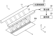
図3に示すように、本実施形態に係る紙葉類識別装置1は、搬送される紙幣BNから発せられた蛍光及び燐光を検知するものであり、光源11、光源制御部21、受光部13、算出部22及び識別部23を備えている。
As shown in FIG. 3, the paper
ここで、紙幣BNは、XY平面内をX方向に搬送される。Y方向が受光部13の主走査方向に対応し、X方向が受光部13の副走査方向に対応している。紙幣BNの少なくとも一部には、蛍光体が含まれる蛍光インクと、燐光体が含まれる燐光インクとが印刷されている。蛍光体は、励起光が照射されると、当該励起光の照射中に蛍光を、例えば可視光領域で発する。燐光体は、励起光が照射されると、当該励起光の消灯後に燐光を、例えば可視光領域で発する。
Here, the banknote BN is conveyed in the X direction within the XY plane. The Y direction corresponds to the main scanning direction of the
光源11は、紙幣BNに対して、励起光を照射する。光源11は、紙幣BNに対して受光部13と同じ側に設けられてもよい。光源11は、紙幣BNに対して、Y方向(主走査方向)に延びる直線状に励起光を照射してもよい。
The
励起光の種類(波長帯域)は特に限定されないが、可視光及び/又は紫外光(UV)が用いられてもよい。 The type (wavelength band) of excitation light is not particularly limited, but visible light and/or ultraviolet light (UV) may be used.
また、光源11は、蛍光体の励起用と燐光体の励起用とにそれぞれ異なる波長帯域の励起光を照射してもよいし、互いの共通の波長帯域の励起光を照射してもよい。
Further, the
光源制御部21は、光源11の点灯及び消灯を制御する。具体的には、光源制御部21による制御の下、光源11は、励起光を点灯期間で照射し、かつ点灯期間後の消灯期間で消灯する。
The light
光源制御部21は、図2に示したように、励起光を複数の点灯期間で照射するように、光源11を制御してもよい。その場合、複数の点灯期間で照射される励起光の種類(波長帯域)は、互いに異なっていてもよいが、通常では同じ種類(波長帯域)である。また、複数の点灯期間の長さ(発光時間)は、互いに異なっていてもよいが、ここでは実質的に同じ長さに設定されている。
The light
また、光源制御部21は、図2に示したように、点灯期間後に複数の消灯期間で消灯するように、光源11を制御してもよい。その場合、複数の消灯期間の長さ(消灯時間)は、互いに異なっていてもよいが、ここでは実質的に同じ長さに設定されている。
Furthermore, as shown in FIG. 2, the light
なお、各点灯期間の長さ(発光時間)は、各消灯期間の長さ(消灯時間)と異なっていてもよいが、ここでは各消灯期間の長さ(消灯時間)と実質的に同じ長さに設定されている。 Note that the length of each lighting period (light emission time) may be different from the length of each lighting period (lights out time), but here, the length of each lighting period (lights out time) is substantially the same as the length of each lighting period (lights out time). It is set to
受光部13は、点灯期間に紙幣BNから発せられる光を受光し、当該光に基づく蛍光燐光検知信号Sfpを出力するとともに、消灯期間に紙幣BNから発せられる光を受光し、当該光に基づく燐光検知信号Spを出力する(図2参照)。より詳細には、図1に示したように、点灯期間に紙幣BNから発せられる光には、蛍光体が発する蛍光成分と、燐光体が発する燐光成分とが含まれている。他方、消灯期間に紙幣BNから発せられる光には、蛍光体が発する蛍光成分は含まれず、燐光体が発する燐光成分が含まれている。そして、受光部13は、入射光量(受光量)に応じた電気信号(デジタル信号でもよい)を出力する。すなわち、蛍光燐光検知信号Sfpは、点灯期間に紙幣BNから発せられた蛍光及び燐光の入射光量に応じた電気信号であり、燐光検知信号Spは、消灯期間に紙幣BNから発せられた燐光の入射光量に応じた電気信号である。
The
受光部13は、Y方向(主走査方向)に一列に配列された複数の画素を備えていてもよい。すなわち、受光部13は、入射光量に応じた電気信号(蛍光燐光検知信号Sfpや燐光検知信号Sp)を、複数の画素(Y方向(主走査方向)の位置)に対応する複数のチャンネルにて出力してもよい。
The
また、受光部13は、紙幣BNから到来した複数の波長帯域の光を受光し、電気信号(蛍光燐光検知信号Sfpや燐光検知信号Sp)を複数の波長帯域毎に出力してもよい。この場合、各画素は、互いに異なる波長帯域の光を選択的に受光する複数の受光素子(撮像素子)を備えていてもよい。
Further, the
光源11が励起光を複数の点灯期間で照射する場合、図2に示したように、受光部13は、複数の点灯期間に紙幣BNから発せられる光を順次受光し、それらの光に基づく複数の蛍光燐光検知信号Sfpを順次出力してもよい。その場合、複数の点灯期間で光を受光する時間(受光時間)は、互いに異なっていてもよいが、ここでは実質的に同じ長さに設定されている。
When the
また、光源11が点灯期間後に複数の消灯期間で消灯する場合、図2に示したように、受光部13は、複数の消灯期間で紙幣BNから発せられる光を順次受光し、それらの光に基づく複数の燐光検知信号Spを順次出力してもよい。その場合、複数の消灯期間で光を受光する時間(受光時間)は、互いに異なっていてもよいが、ここでは実質的に同じ長さに設定されている。
Further, when the
なお、各点灯期間で光を受光する時間(受光時間)は、各消灯期間で光を受光する時間(受光時間)と異なっていてもよいが、ここでは各消灯期間で光を受光する時間(受光時間)と実質的に同じ長さに設定されている。 Note that the time for receiving light in each lighting period (light receiving time) may be different from the time for receiving light in each turning off period (light receiving time), but here, the time for receiving light in each turning off period (light receiving time) The length is set to be substantially the same as the light reception time).
より具体的には、例えば、光源制御部21は、図4に示す制御パターンにより光源11の点灯及び消灯を制御してもよいし、受光部13は、図4に示す制御パターンにより検知信号を順次出力してもよい。なお、図4において、UV1~UV5は、光源11が励起光を照射する点灯期間であり、受光部13が点灯期間で紙幣BNから発せられる光を受光して蛍光燐光検知信号Sfpを出力するフェーズを示している。また、PH1~PH4は、光源11が励起光を照射しない消灯期間であり、受光部13が消灯期間で紙幣BNから発せられる光を受光して燐光検知信号Spを出力するフェーズを示している。更に、空欄は、光源11の点灯及び受光部13の受光も行わないブランクのフェーズであってもよいし、反射画像又は透過画像を取得するためのフェーズであってもよい。
More specifically, for example, the light
このように、隣り合う2つの点灯期間の間や隣り合う2つの消灯期間の間、隣り合う2つの点灯期間と消灯期間の間には、ブランクのフェーズや反射画像又は透過画像を取得するためのフェーズ等を適宜設けてもよい。 In this way, between two adjacent lighting periods, between two adjacent lighting periods, or between two adjacent lighting periods and a lighting-off period, there is a blank phase, a reflection image, or a transmission image. Phases etc. may be provided as appropriate.
算出部22は、蛍光燐光検知信号Sfpにおける推定燐光信号値を算出する。ここで、推定燐光信号値とは、受光部13が紙幣BNから受光した燐光に基づくと推定される信号値である。すなわち、蛍光燐光検知信号Sfpは、点灯期間に紙幣BNから発せられた蛍光及び燐光の入射光量に応じた電気信号であり、蛍光燐光検知信号Sfpの信号値は、蛍光の入射光量に応じた信号値と、燐光の入射光量に応じた信号値とを合算したものと考えらえるが、推定燐光信号値は、このうちの燐光の入射光量に応じた信号値に相当するものである。
The
ただし、推定燐光信号値は、この燐光の入射光量に応じた信号値の傾向を捉えたものであればよく、燐光の入射光量に応じた信号値に必ずしも厳密に一致する必要はない。本実施形態では、燐光体の時定数そのものを算出することが目的ではなく、燐光体の時定数に応じた評価値等の特徴に基づいて紙幣BNを識別することが目的であるためである。 However, the estimated phosphorescence signal value only needs to capture the tendency of the signal value according to the amount of incident phosphorescence light, and does not necessarily need to exactly match the signal value according to the amount of incident phosphorescence light. This is because the purpose of this embodiment is not to calculate the time constant of the phosphor per se, but to identify the banknote BN based on characteristics such as an evaluation value according to the time constant of the phosphor.
なお、「信号値」とは、当該信号の光強度(明るさ)を示すものであり、受光部13が複数の画素を備える場合は画素値で表される。
Note that the "signal value" indicates the light intensity (brightness) of the signal, and when the
そして、識別部23は、推定燐光信号値に基づいて紙幣BNを識別する。このため、上述のように、識別部23は、燐光に基づき紙幣BNを高精度に識別することができる。
Then, the
より具体的には、識別部23は、推定燐光信号値及び燐光検知信号Spの信号値のうちの少なくとも1つの信号値に基づいて紙幣BNから発せられる燐光の有無を判定してもよい。これにより、短時間検知で燐光の有無判別を行うことができる。以下、燐光検知信号Spの信号値を燐光信号値と言う場合がある。
More specifically, the
識別部23は、推定燐光信号値及び燐光信号値の合算値に基づいて紙幣BNから発せられる燐光の有無を判定してもよい。また、上述のように、受光部13が複数の蛍光燐光検知信号Sfpを順次出力するとともに複数の燐光検知信号Spを順次出力する場合、識別部23は、複数の推定燐光信号値及び複数の燐光信号値の全ての合算値に基づいて紙幣BNから発せられる燐光の有無を判定してもよい。
The
他方、識別部23は、燐光信号値のみに基づいて、例えば点灯期間の後に初めに到来する消灯期間に得られた燐光信号値のみに基づいて、紙幣BNから発せられる燐光の有無を判定してもよい。以下、点灯期間の後に初めに到来する消灯期間を1番目の消灯期間と言う場合がある。
On the other hand, the
また、識別部23は、2つの波長帯域の信号値(推定燐光信号値及び/又は燐光信号値)を互いに合算し、得られた合算値に基づいて紙幣BNから発せられる燐光の有無を判定してもよい。これにより、ブロード又は中間色の燐光の有無を判定することができる。例えば、黄色発光であれば、赤色の波長帯域の信号値と緑色の波長帯域の信号値の合算値で判定することができる。
Further, the
算出部22は、複数の波長帯域毎に推定燐光信号値を算出してもよく、識別部23は、複数の波長帯域毎の推定燐光信号値と、複数の波長帯域毎の燐光検知信号の信号値(燐光信号値)との少なくとも一方に基づいて紙幣BNから発せられる燐光の色を判定してもよい。これにより、短時間検知で燐光の色判別を行うことができる。
The
より詳細には、識別部23は、複数の波長帯域毎の推定燐光信号値と、複数の波長帯域毎の燐光信号値とを波長帯域毎に合算し、得られた波長帯域毎の合算値に基づいて紙幣BNから発せられる燐光の色を判定してもよい。
More specifically, the
なお、「複数の波長帯域」とは、例えば、赤色の波長帯域(概ね600nm~750nm)、緑色の波長帯域(概ね500nm~600nm)、青色の波長帯域(概ね400nm~500nm)、及び赤外光の波長帯域(概ね750nm~1500nm)のうちの少なくとも2つの波長帯域であってもよい。すなわち、識別部23によって判定される色は、可視領域の色に限定されず、可視以外の波長領域の光(例えば赤外光)が含まれていてもよい。
Note that "multiple wavelength bands" include, for example, a red wavelength band (approximately 600 nm to 750 nm), a green wavelength band (approximately 500 nm to 600 nm), a blue wavelength band (approximately 400 nm to 500 nm), and infrared light. The wavelength band may be at least two of the wavelength bands (approximately 750 nm to 1500 nm). That is, the colors determined by the
また、ここで、識別部23による色判定処理に使用される信号値の波長帯域の種類は、受光部13から出力される信号の波長帯域の種類と完全に対応(一致)していてもよいし、少なとも一部が対応(一致)していなくてもよい。前者の場合、例えば、受光部13からR、G、B信号が出力され、識別部23によりR、G、B信号毎に色判定処理が行われてもよい。後者の場合、例えば、受光部13からR、G、B信号(ただし、いずれもIR成分を含む)が出力され、識別部23によりR、G、IR信号毎に色判定処理が行われてもよい。
Further, here, the type of wavelength band of the signal value used for the color determination process by the
また、ブロード発光の場合は、例えば、B信号及びG信号の合算値、G信号及びR信号の合算値、R信号及びIR信号の合算値、又はG信号、R信号及びIR信号の合算値に基づいて色判定処理が行われてもよい。緑の波長帯域を中心としたブロードで弱い発光の場合、各波長帯域の信号量は小さいため判定し難いが、G信号、R信号及びIR信号の合算値に基づけば色判定できる場合もある。また、B信号、G信号及びR信号の合算値から白色を判定してもよい。更に、後述するSO補正を行わない場合、B信号、G信号及びR信号の信号値が互いに実質的に同じであれば、白色又は赤外光である判定してもよい。 In the case of broad light emission, for example, the total value of B signal and G signal, the total value of G signal and R signal, the total value of R signal and IR signal, or the total value of G signal, R signal, and IR signal. Color determination processing may be performed based on this. In the case of broad and weak light emission centered on the green wavelength band, it is difficult to judge because the signal amount in each wavelength band is small, but it may be possible to judge the color based on the sum of the G signal, R signal, and IR signal. Alternatively, white may be determined from the sum of the B signal, G signal, and R signal. Furthermore, if the SO correction described later is not performed, if the signal values of the B signal, G signal, and R signal are substantially the same, it may be determined that the light is white or infrared light.
なお、ここまで、推定燐光信号値及び/又は燐光検知信号に基づく燐光の有無判定及び色判定について説明したが、これと同様にして、蛍光燐光検知信号Sfpの信号値や、後述する推定蛍光信号値に基づいて蛍光の有無判定や色判定を行ってもよい。 Up to this point, we have described the presence/absence determination of phosphorescence and color determination based on the estimated phosphorescence signal value and/or the phosphorescence detection signal. The presence or absence of fluorescence or the color may be determined based on the value.
識別部23は、推定燐光信号値及び燐光検知信号の信号値(燐光信号値)を規格化し、その規格化した信号値に基づいて紙幣BNに設けられた燐光体の識別を行ってもよい。これにより、個々の紙幣の印刷濃度の影響を低減できるため、より安定的に時定数に基づく識別が可能である。
The
より詳細には、識別部23は、1番目の消灯期間に得られた燐光信号値で規格化してもよい。すなわち、識別部23は、推定燐光信号値及び燐光信号値を、1番目の消灯期間に得られた燐光信号値で除算することによって規格化してもよい。
More specifically, the
識別部23は、推定燐光信号値及び燐光検知信号の信号値(燐光信号値)の少なくとも一方に基づいて燐光の時定数に応じて変動する判定値を算出し、その判定値に基づいて紙幣BNに設けられた燐光体(例えば燐光インク)の識別を行ってもよい。これにより、燐光体の時定数の違いにより紙幣BNを判別できることから、紙幣BNの識別精度をより向上することができる。以下、燐光の時定数に応じて変動する判定値を時定数判定値と言う場合がある。
The
具体的な時定数判定値は、特に限定されないが、時定数判定値は、例えば、複数の点灯期間のうちの最後の点灯期間で得られた推定燐光信号値と、1番目の消灯期間で得られた燐光信号値とから算出されてもよい。また、複数の点灯期間のうちの1番目の点灯期間で得られた推定燐光信号値と、1番目の消灯期間で得られた燐光信号値とから時定数判定値が算出されてもよい。いずれの場合も、2つの信号値(上述のように規格化した信号値でもよい)の差分や比率を時定数判定値としてもよい。更に、複数の点灯期間のうちの最後の点灯期間で得られた推定燐光信号値をそのまま、又は上述のように規格化し、時定数判定値としてもよい。 Although the specific time constant judgment value is not particularly limited, the time constant judgment value may be, for example, an estimated phosphorescence signal value obtained in the last lighting period of a plurality of lighting periods and a value obtained in the first lighting period. It may be calculated from the phosphorescence signal value obtained. Further, the time constant determination value may be calculated from the estimated phosphorescence signal value obtained in the first lighting period of the plurality of lighting periods and the phosphorescence signal value obtained in the first non-lighting period. In either case, a difference or a ratio between two signal values (which may be normalized signal values as described above) may be used as the time constant determination value. Further, the estimated phosphorescence signal value obtained in the last lighting period among the plurality of lighting periods may be used as it is, or may be normalized as described above and used as the time constant determination value.
なお、光源制御部21、算出部22及び識別部23は、後述する制御部によってそれぞれ対応するプログラムを実行することによって機能してもよい。
Note that the light
次に、図5を用いて、本実施形態に係る紙葉類識別装置1の動作について説明する。
Next, the operation of the paper
図5に示すように、まず、光源11が、紙幣BNに対して励起光を点灯期間で照射するとともに、点灯期間後の消灯期間で消灯する(ステップS11)。
As shown in FIG. 5, first, the
次に、受光部13が、点灯期間に紙幣BNから発せられる光に基づく蛍光燐光検知信号Sfpを出力するとともに、消灯期間に紙幣BNから発せられる光に基づく燐光検知信号Spを出力する(ステップS12)。
Next, the
次に、算出部22が、蛍光燐光検知信号Sfpにおいて推定燐光信号値を算出する(ステップS13)。
Next, the
その後、識別部23が、推定燐光信号値に基づいて紙幣BNを識別し(ステップS14)、紙葉類識別装置1の動作が終了する。
Thereafter, the
(実施形態2)
本実施形態では、実施形態1の算出部による推定燐光信号値のより具体的な算出方法について説明する。
(Embodiment 2)
In this embodiment, a more specific method of calculating an estimated phosphorescence signal value by the calculation unit of
図6に示すように、本実施形態では、光源制御部(図示せず)は、励起光を複数の点灯期間で照射するように、光源(図示せず)を制御し、受光部(図示せず)は、複数の点灯期間に紙幣BNから発せられる光に基づく複数の蛍光燐光検知信号を順次出力する。 As shown in FIG. 6, in this embodiment, the light source control unit (not shown) controls the light source (not shown) to emit excitation light in a plurality of lighting periods, and the light receiving unit (not shown) controls the light source (not shown) to emit excitation light in multiple lighting periods. ) sequentially outputs a plurality of fluorescent phosphorescence detection signals based on the light emitted from the banknote BN during a plurality of lighting periods.
そして、算出部(図示せず)は、複数の蛍光燐光検知信号Sfpのうち、2番目以降の出力された蛍光燐光検知信号Sfpの信号値から、1番目に出力された蛍光燐光検知信号Sfpの信号値を減算することによって、2番目以降の出力された蛍光燐光検知信号Sfpにおいて推定燐光信号値を算出する。これにより、推定燐光信号値として、その点灯期間よりも前の点灯期間での励起光照射によって増加した後で減衰した燐光成分(残光成分)に基づくものと推定される信号値を算出することができる。 Then, a calculation unit (not shown) calculates the first output fluorescence phosphorescence detection signal Sfp from the signal value of the second and subsequent output fluorescence phosphorescence detection signals Sfp among the plurality of fluorescence phosphorescence detection signals Sfp. By subtracting the signal values, estimated phosphorescence signal values are calculated for the second and subsequent output fluorescent phosphorescence detection signals Sfp. As a result, a signal value that is estimated to be based on a phosphorescent component (afterglow component) that has increased and then attenuated due to excitation light irradiation in a lighting period prior to the lighting period is calculated as an estimated phosphorescence signal value. Can be done.
例えば、図6に示した例では、2番目の出力された蛍光燐光検知信号Sfpから、1番目の点灯期間での励起光照射によって増加した後で減衰した燐光成分ph1の信号値を算出することができる。また、3番目の出力された蛍光燐光検知信号Sfpから、この燐光成分ph1の信号値と、2番目の点灯期間での励起光照射によって増加した後で減衰した燐光成分ph2の信号値との合算値を算出することができる。 For example, in the example shown in FIG. 6, the signal value of the phosphorescence component ph1, which increased and then attenuated due to excitation light irradiation in the first lighting period, is calculated from the second output fluorescent phosphorescence detection signal Sfp. Can be done. Also, from the third outputted fluorescence phosphorescence detection signal Sfp, the signal value of this phosphorescence component ph1 and the signal value of the phosphorescence component ph2 which increased and then attenuated due to excitation light irradiation in the second lighting period are summed. The value can be calculated.
図7に示すように、本実施形態では、光源制御部は、複数の点灯期間の前に、複数の点灯期間のうちの1番目の点灯期間よりも短く、かつ紙幣BNから実質的に燐光が発しない短期間、励起光を照射するように、光源を制御してもよく、受光部は、この短期間に紙幣BNから発せられる光に基づく蛍光検知信号Sfを出力してもよい。 As shown in FIG. 7, in the present embodiment, the light source control unit, before the plurality of lighting periods, causes the lighting period to be shorter than the first lighting period among the plurality of lighting periods, and substantially emit phosphorescence from the banknote BN. The light source may be controlled so as to irradiate excitation light for a short period of time when no excitation light is emitted, and the light receiving section may output a fluorescence detection signal Sf based on the light emitted from the banknote BN during this short period of time.
ここで、1番目の点灯期間の時間をTとし、この短期間の時間をtとしたとき、算出部は、1番目に出力された蛍光燐光検知信号Sfpの信号値から、蛍光検知信号Sfの信号値を(T/t)倍した値を減算することによって、1番目に出力された蛍光燐光検知信号Sfpにおいて推定燐光信号値を算出してもよい。これにより、推定燐光信号値として、1番目の点灯期間での励起光照射によって増加した燐光成分に基づくものと推定される信号値を算出することができる。 Here, when the time of the first lighting period is T and the time of this short period is t, the calculation unit calculates the fluorescence detection signal Sf from the signal value of the first output fluorescent phosphorescence detection signal Sfp. The estimated phosphorescence signal value may be calculated in the first output fluorescent phosphorescence detection signal Sfp by subtracting a value obtained by multiplying the signal value by (T/t). Thereby, a signal value estimated to be based on the phosphorescence component increased by the excitation light irradiation during the first lighting period can be calculated as the estimated phosphorescence signal value.
(実施形態3)
本実施形態では、実施形態1の算出部による推定燐光信号値のより具体的な他の算出方法について説明する。
(Embodiment 3)
In this embodiment, another more specific calculation method of the estimated phosphorescence signal value by the calculation unit of
図8に示すように、本実施形態では、光源制御部(図示せず)は、励起光を複数の点灯期間で照射し、かつ複数の点灯期間後に複数の消灯期間で消灯するように、光源(図示せず)を制御し、受光部(図示せず)は、複数の点灯期間に紙幣BNから発せられる光に基づく複数の蛍光燐光検知信号Sfpを順次出力するとともに、複数の消灯期間で紙幣BNから発せられる光に基づく複数の燐光検知信号Spを順次出力する。 As shown in FIG. 8, in the present embodiment, the light source control unit (not shown) controls the light source so that the excitation light is emitted in a plurality of lighting periods and is turned off in a plurality of off periods after the plurality of lighting periods. (not shown), and the light receiving unit (not shown) sequentially outputs a plurality of fluorescent phosphorescence detection signals Sfp based on the light emitted from the banknote BN during a plurality of lighting periods, and outputs a plurality of fluorescent phosphorescence detection signals Sfp based on the light emitted from the banknote BN during a plurality of lighting periods, and a A plurality of phosphorescence detection signals Sp based on light emitted from the BN are sequentially output.
そして、算出部(図示せず)は、複数の蛍光燐光検知信号Sfp及び複数の燐光検知信号Spに基づいて、複数の蛍光燐光検知信号Sfpにおいて、受光部が紙幣BNから受光した蛍光に基づく信号値と推定される推定蛍光信号値を算出する。これにより、推定蛍光信号値を用いて各蛍光燐光検知信号Sfpから推定燐光信号値を算出することができる。 Then, based on the plurality of fluorescent phosphorescence detection signals Sfp and the plurality of phosphorescence detection signals Sp, the calculation section (not shown) calculates a signal based on the fluorescence received by the light receiving section from the banknote BN in the plurality of fluorescent phosphorescence detection signals Sfp. Calculate the estimated fluorescence signal value. Thereby, the estimated phosphorescence signal value can be calculated from each fluorescence phosphorescence detection signal Sfp using the estimated fluorescence signal value.
具体的には、算出部は、複数の蛍光燐光検知信号Sfpの少なくとも1つの信号値から、少なくとも推定蛍光信号値を減算することによって、当該蛍光燐光検知信号Sfpにおいて、推定燐光信号値を算出してもよい。これにより、推定燐光信号値として、蛍光成分を除く燐光成分(残光成分)に基づくものと推定される信号値を算出することができる。 Specifically, the calculation unit calculates the estimated phosphorescence signal value in the fluorescent phosphorescence detection signal Sfp by subtracting at least the estimated fluorescence signal value from at least one signal value of the plurality of fluorescent phosphorescence detection signals Sfp. You can. Thereby, a signal value estimated to be based on a phosphorescence component (an afterglow component) excluding a fluorescence component can be calculated as an estimated phosphorescence signal value.
本実施形態では、図9に示すように、光源は、受光部の測定位置と、紙幣BNの搬送方向(図9中の矢印方向)において測定位置の上流側に位置する領域と、を少なくとも含む領域に励起光を照射してもよい。例えば、光源は、測定位置と、紙幣BNの搬送方向において測定位置の上流側及び下流側にそれぞれ位置する領域と、を含む領域に励起光を照射してもよい。 In this embodiment, as shown in FIG. 9, the light source includes at least the measurement position of the light receiving unit and a region located upstream of the measurement position in the transport direction of the banknote BN (arrow direction in FIG. 9). The region may be irradiated with excitation light. For example, the light source may irradiate excitation light to a region including the measurement position and regions located upstream and downstream of the measurement position in the transport direction of the banknote BN.
また、光源制御部は、複数の点灯期間及び複数の消灯期間を含む所定のサイクルを繰り返すように、光源を制御してもよい。これにより、受光部の測定位置に該当するサイクルにて励起及び信号検知される紙幣BNの検知領域(蛍光体及び燐光体)は、その前の少なくとも1回のサイクルにおいても測定位置の上流側において励起光が照射されて励起されることになる。 Further, the light source control unit may control the light source to repeat a predetermined cycle including a plurality of lighting periods and a plurality of lighting periods. As a result, the detection region (fluorescent material and phosphor material) of the banknote BN that is excited and signal-detected in the cycle corresponding to the measurement position of the light receiving section is also on the upstream side of the measurement position in at least one previous cycle. Excitation light is irradiated to excite it.
そして、算出部は、推定燐光信号値として、測定位置に到達する前に紙幣BNに照射された励起光による燐光の残光成分PHn(図8参照)に基づくものと推定される信号値を算出してもよい。以下、この信号値を推定残光信号値と言う場合がある。 Then, the calculation unit calculates, as the estimated phosphorescence signal value, a signal value that is estimated to be based on the afterglow component PHn of phosphorescence (see FIG. 8) caused by the excitation light irradiated on the banknote BN before reaching the measurement position. You may. Hereinafter, this signal value may be referred to as an estimated afterglow signal value.
推定残光信号値を算出することで、消灯期間から減衰時間が最も離れた燐光光量値を推定できる。そのため、例えば、推定残光信号値と、1番目の消灯期間に得られた燐光信号値とから時定数判定値を算出して燐光インク等の燐光体を識別できる。その結果、1サイクル内の燐光検知期間より時定数が長い燐光インクの検知誤差を低減できる。例えば、図8において、2番目に出力された蛍光燐光検知信号Sfp、3番目に出力された蛍光燐光検知信号Sfp、・・・、3番目に出力された燐光検知信号Sp、1番目に出力された蛍光燐光検知信号Sfpを1サイクルと考えて、1番目~3番目の消灯期間に得られた燐光信号値と、1番目に出力された蛍光燐光検知信号Sfpから算出された推定残光信号値とを用いて燐光体の時定数を判定してもよい。 By calculating the estimated afterglow signal value, it is possible to estimate the phosphorescence amount value whose decay time is farthest from the lights-out period. Therefore, for example, a phosphor such as a phosphorescent ink can be identified by calculating a time constant determination value from the estimated afterglow signal value and the phosphorescence signal value obtained during the first light-off period. As a result, the detection error of phosphorescent ink whose time constant is longer than the phosphorescent detection period within one cycle can be reduced. For example, in FIG. 8, the second outputted fluorescent phosphorescence detection signal Sfp, the third outputted fluorescent phosphorescence detection signal Sfp, ..., the third outputted phosphorescence detection signal Sp, the first outputted Considering the fluorescent phosphorescence detection signal Sfp as one cycle, the estimated afterglow signal value is calculated from the phosphorescence signal values obtained during the first to third turn-off periods and the first output fluorescent phosphorescence detection signal Sfp. may be used to determine the time constant of the phosphor.
なお、実施形態2においても、図9に示したように測定位置に達する前に励起が繰り返されてもよく、その場合であっても実施形態2の算出方法により推定燐光信号値を算出することができる。
Note that in
(実施形態4)
本実施形態では、実施形態2の紙葉類識別装置のより具体的な例について説明する。まず、図10を用いて、本実施形態の概要について説明する。
(Embodiment 4)
In this embodiment, a more specific example of the paper sheet identification device of
図10に示すように、本実施形態では、例えば、光源(図示せず)から励起光としての紫外光を3つの点灯期間で紙幣に照射し、各点灯期間で紙幣から発せられる光を受光部(図示せず)で受光する。また、3つの点灯期間後に3つの消灯期間で光源を消灯した状態で、各消灯期間で紙幣から発せられる光を受光部で受光する。このとき、各点灯期間で受光される光には、蛍光成分と、励起光の照射に応じて増加する燐光成分p1、p2又はp3とが含まれる。また、2番目以降の点灯期間では、前の点灯期間での励起光照射によって増加した後で減衰した燐光成分(残光成分)ph1又はph2が含まれる。また、各消灯期間で受光される光には、いずれかの点灯期間での励起光照射によって増加した後で減衰した燐光成分(残光成分)ph1、ph2及びph3が含まれる。この各燐光成分ph1、ph2、ph3の燐光量は、時間経過に伴い減少していく。 As shown in FIG. 10, in this embodiment, for example, ultraviolet light as excitation light is irradiated onto a banknote from a light source (not shown) in three lighting periods, and the light emitted from the banknote in each lighting period is transmitted to the light receiving unit. (not shown). Furthermore, with the light source turned off during three turn-off periods after three turn-on periods, the light-receiving section receives light emitted from the bill during each turn-off period. At this time, the light received in each lighting period includes a fluorescent component and a phosphorescent component p1, p2, or p3 that increases depending on the irradiation of the excitation light. In addition, the second and subsequent lighting periods include a phosphorescent component (afterglow component) ph1 or ph2 that has been increased by excitation light irradiation in the previous lighting period and then attenuated. Further, the light received in each light-off period includes phosphorescence components (afterglow components) ph1, ph2, and ph3 that are increased by excitation light irradiation in any of the light-on periods and then attenuated. The amount of phosphorescence of each of the phosphorescent components ph1, ph2, and ph3 decreases over time.
ここで、励起光の照射に応じて増加する燐光成分p1、p2及びp3の燐光量は、厳密には互いに異なるが、その変動量は小さいため、励起光の照射に応じて増加する燐光成分p1、p2及びp3の燐光量は同じであると仮定する。すると、1番目の点灯期間における蛍光成分と燐光成分p1の合計量は、2番目の点灯期間における蛍光成分と燐光成分p2の合計量と等しくなる。したがって、各点灯期間での蛍光燐光検知信号Sfpに占める燐光信号を推定することが可能である。 Here, the amounts of phosphorescence of the phosphorescent components p1, p2, and p3, which increase in accordance with the irradiation of the excitation light, are strictly different from each other, but since the amount of variation is small, the phosphorescence component p1, which increases in response to the irradiation of the excitation light, is different from each other. , p2 and p3 are assumed to have the same amount of phosphorescence. Then, the total amount of the fluorescent component and the phosphorescent component p1 in the first lighting period becomes equal to the total amount of the fluorescent component and the phosphorescent component p2 in the second lighting period. Therefore, it is possible to estimate the phosphorescence signal that occupies the fluorescence phosphorescence detection signal Sfp in each lighting period.
より具体的には、2番目の蛍光燐光検知信号Sfpの信号値から1番目の蛍光燐光検知信号Sfpの信号値を減算することによって、推定燐光信号値として、燐光成分(残光成分)ph1による信号値を算出(推定)できる。また、3番目の蛍光燐光検知信号Sfpの信号値から1番目の蛍光燐光検知信号Sfpの信号値を減算することによって、推定燐光信号値として、燐光成分(残光成分)ph1及びph2による信号値を算出(推定)できる。 More specifically, by subtracting the signal value of the first fluorescent phosphorescence detection signal Sfp from the signal value of the second fluorescent phosphorescence detection signal Sfp, the estimated phosphorescence signal value is determined by the phosphorescence component (afterglow component) ph1. Signal values can be calculated (estimated). In addition, by subtracting the signal value of the first fluorescent phosphorescence detection signal Sfp from the signal value of the third fluorescent phosphorescence detection signal Sfp, the signal value due to the phosphorescence components (afterglow components) ph1 and ph2 is obtained as an estimated phosphorescence signal value. can be calculated (estimated).
そして、最後の点灯期間における推定燐光信号値(ph1及びph2)と、1番目の消灯期間における燐光信号値(ph1、ph2及びph3)とを用いて時定数評価値を算出し、その評価値に基づいて燐光インクの判別を行う。 Then, a time constant evaluation value is calculated using the estimated phosphorescence signal values (ph1 and ph2) in the last lighting period and the phosphorescence signal values (ph1, ph2, and ph3) in the first lighting period, and the evaluation value is The phosphorescent ink is determined based on this.
次に、図11を用いて、本実施形態に係る紙葉類処理装置の構成について説明する。 Next, the configuration of the paper sheet processing apparatus according to this embodiment will be described using FIG. 11.
本実施形態に係る紙葉類処理装置は、例えば、図11に示す構成を有するものであってもよい。図11に示す紙葉類処理装置300は、テーブル上に設置して利用する小型の紙葉類処理装置であり、紙幣の識別処理を行う紙葉類識別装置(図11では図示せず)と、処理対象の複数の紙幣が積層状態で載置されるホッパ301と、ホッパ301から筐体304内に繰り出された紙幣が偽造券、真偽不確定券等のリジェクト紙幣であった場合に該リジェクト紙幣が排出される2つのリジェクト部302と、オペレータからの指示を入力するための操作部303と、筐体304内で金種、真偽及び正損が識別された紙幣を分類して集積するための4つの集積部306a~306dと、紙幣の識別計数結果や各集積部306a~306dの集積状況等の情報を表示するための表示部305とを備える。紙葉類識別装置による正損判定の結果に基づき、4つの集積部306a~306dのうち、集積部306a~306cには、正券が収納され、集積部306dには汚損券が収納される。なお、集積部306a~306dへの紙幣の振り分け方法は任意に設定可能である。
The paper sheet processing apparatus according to this embodiment may have the configuration shown in FIG. 11, for example. The paper
次に、図12を用いて、本実施形態に係る紙葉類識別装置の主要部である撮像部の構成について説明する。図12に示すように、撮像部211は、互いに対向配置された上部ユニット110及び下部ユニット120を備えている。Z方向において離間した上部ユニット110及び下部ユニット120の間には、紙幣BNがXY平面内をX方向に搬送される隙間が形成されており、この隙間は本実施形態に係る紙葉類処理装置の搬送路の一部を構成する。上部ユニット110及び下部ユニット120は、それぞれ、搬送路の上側(+Z方向)及び下側(-Z方向)に位置している。Y方向が撮像部211の主走査方向に対応し、X方向が撮像部211副走査方向に対応している。
Next, with reference to FIG. 12, the configuration of the imaging unit, which is the main part of the paper sheet identification device according to this embodiment, will be described. As shown in FIG. 12, the
図12に示すように、上部ユニット110は、2つの反射用の光源111、集光レンズ112及び受光部113を備えている。反射用の光源111は、紙幣BNの受光部113側の主面(以下、A面)に、波長帯域が互いに異なる照射光、具体的には、赤外光と、赤色光、緑色光及び青色光を含む白色光と、蛍光及び燐光用の励起光としての紫外光とを順次照射する。集光レンズ112は、反射用の光源111から出射され、紙幣BNのA面で反射された光と、下部ユニット120に設けられた透過用の光源124から出射され、紙幣BNを透過した光と、紙幣BNのA面で発光した蛍光及び燐光とを集光する。受光部113は、集光レンズ112によって集光された光を受光して電気信号に変換する。そして、その電気信号を増幅処理した後、デジタルデータにA/D変換した上で出力する。ここで、受光部が受光する光を入射光ともいい、光源が照射する光を照射光ともいう。
As shown in FIG. 12, the
下部ユニット120は、2つの反射用の光源121及び1つの透過用の光源124、集光レンズ122並びに受光部123を備えている。反射用の光源121は、紙幣BNの受光部123側の主面(以下、B面)に、波長帯域が互いに異なる照射光、具体的には、赤外光と、赤色光、緑色光及び青色光を含む白色光と、蛍光及び燐光用の励起光としての紫外光とを照射する。集光レンズ122は、反射用の光源121から出射され、紙幣BNのB面で反射された光と、紙幣BNのB面で発光した蛍光及び燐光とを集光する。受光部123は、集光レンズ122によって集光された光を受光して電気信号に変換する。そして、その電気信号を増幅処理した後、デジタルデータにA/D変換した上で出力する。
The
透過用の光源124は、上部ユニット110の集光レンズ112の光軸上に配置されており、透過用の光源124から出射された光の一部は、紙幣BNを透過し、上部ユニット110の集光レンズ112に集光されて受光部113で検出される。透過用の光源124は、紙幣BNのB面に、波長帯域が互いに異なる照射光を順次照射してもよいし、同時に照射してもよい。
The
なお、本明細書にて、波長帯域が互いに異なる光(照射光、入射光等)とは、例えば、可視光については色が互いに異なる光であり、赤外光及び紫外光については、波長帯域の一部のみが互いに重なる光又は波長帯域が互いに重ならない光である。 Note that in this specification, light with different wavelength bands (irradiated light, incident light, etc.) refers to, for example, visible light with different colors, and infrared light and ultraviolet light with different wavelength bands. This is light whose wavelength bands only partially overlap with each other, or whose wavelength bands do not overlap with each other.
各光源111、121、124は、図12の紙面に垂直な方向(主走査方向D1)に延びるライン状の導光体(図示せず)と、導光体の両端部(一方の端部でもよい)に設けられた複数のLED素子(図示せず)とを備えている。
Each of the
各光源111、121は、ピーク波長が750nm以上である赤外光を発光するLED素子と、ピーク波長が600nm以上、750nm未満である赤色光(R)を発光するLED素子と、ピーク波長が500nm以上、600nm未満である緑色光(G)を発光するLED素子と、ピーク波長が400nm以上、500nm未満である青色光(B)を発光するLED素子と、を備えていてもよい。光源111は、集光レンズ112を挟んで搬送方向の上流側及び下流側に1つずつ配置され、光源121は、集光レンズ122を挟んで搬送方向の上流側及び下流側に1つずつ配置される。
Each of the
光源124は、互いに異なるピーク波長を有する光を発光する複数のLED素子を備えていてもよい。なお、ピーク波長とは、光の発光強度が最大となる波長をいう。
The
図13に示すように、各受光部113、123は、主走査方向D1(紙幣BNの搬送方向に対して直交する方向、Y方向)に一列に配列された複数の画素131GPを備え、各画素131GPは、第1の受光素子(撮像素子)131Bを1つ、第2の受光素子(撮像素子)131Gを1つ、及び第3の受光素子(撮像素子)131Rを1つ備えており、第1の受光素子131B、第2の受光素子131G及び第3の受光素子131Rは、この順番で主走査方向D1に一列に配置されている。
As shown in FIG. 13, each
第1の受光素子131Bは、光検出器1310と、赤外光及び青色光を透過し、かつ赤色光及び緑色光を吸収する青色のカラーレジスト(カラーフィルタ)1311Bと、を備える青色の受光素子である。第2の受光素子131Gは、光検出器1310と、赤外光及緑色光を透過し、かつ赤色光及び青色光を吸収する緑色のカラーレジスト(カラーフィルタ)1311Gと、を備える緑色の受光素子である。第3の受光素子131Rは、光検出器1310と、赤外光及び赤色光を透過し、かつ緑色光及び青色光を吸収する赤色のカラーレジスト(カラーフィルタ)1311Rと、を備える赤色の受光素子である。
The first
ここで、受光素子(撮像素子)とは、所定の波長帯域の光の強度を検出(電気信号に変換)する素子を意味し、フォトダイオード等の光検出器と、光検出器の受光面上に設けられ、検出すべき所定の波長帯域(例えば青色と赤外の波長帯域)を除く波長帯域(例えば緑色と赤色等)の光の透過を抑えるカラーレジストとを含んで構成されてもよい。 Here, the light-receiving element (imaging element) means an element that detects the intensity of light in a predetermined wavelength band (converts it into an electrical signal), and includes a photodetector such as a photodiode and a light-receiving surface of the photodetector. It may also be configured to include a color resist that is provided to suppress transmission of light in wavelength bands (for example, green and red) other than predetermined wavelength bands to be detected (for example, blue and infrared wavelength bands).
図14に示すように、青色のカラーレジスト(カラーフィルタ)1311Bは主に青色光及び赤外光を透過し(破線参照)、緑色のカラーレジスト(カラーフィルタ)1311Gは主に緑色光及び赤外光を透過し(一点鎖線参照)、赤色のカラーレジスト(カラーフィルタ)1311Rは主に赤色光及び赤外光を透過する(二点鎖線参照)。したがって、第1の受光素子131B、第2の受光素子131G及び第3の受光素子131Rは、それぞれ、青色光(概ね波長400nm~500nm)、緑色光(概ね波長500nm~600nm)及び赤色光(概ね波長600nm~750nm)を選択的に受光可能であり、第1の受光素子131B、第2の受光素子131G及び第3の受光素子131Rはいずれも赤外光(概ね波長750nm~1500nm)を受光可能である。
As shown in FIG. 14, the blue color resist (color filter) 1311B mainly transmits blue light and infrared light (see broken line), and the green color resist (color filter) 1311G mainly transmits green light and infrared light. The red color resist (color filter) 1311R mainly transmits red light and infrared light (see the two-dot chain line). Therefore, the first light-receiving
ただし、各色のカラーレジストは、通常、対応する色以外の色の光もある程度は透過し得るため、第1の受光素子131B、第2の受光素子131G及び第3の受光素子131Rは、対応する色以外の色の光もある程度は受光してもよい。
However, since the color resist of each color can usually transmit a certain amount of light of colors other than the corresponding color, the first
上部ユニット110及び下部ユニット120がそれぞれ、搬送方向に搬送されている紙幣BNに対して撮像を繰り返し行い、受光量に応じた信号を出力することによって、撮像部211は、紙幣BN全体の画像を取得する。具体的には、撮像部211は、上部ユニット110の出力信号に基づいて紙幣BNの透過画像、A面の反射画像を取得し、下部ユニット120の出力信号に基づいて紙幣BNのB面の反射画像を取得する。
The
また、撮像部211は、紙幣BNのA面及びB面のそれぞれにおいて紙幣BN全体で蛍光燐光検知信号及び燐光検知信号を取得する。すなわち、撮像部211は、紙幣BNのA面及びB面それぞれの蛍光画像(燐光成分を含む)及び燐光画像を取得可能である。
The
次に、図15を用いて、本実施形態に係る紙葉類識別装置の構成について説明する。図15に示すように、本実施形態に係る紙葉類識別装置200は、検出部210、制御部220及び記憶部230を備えている。
Next, the configuration of the paper sheet identification device according to this embodiment will be explained using FIG. 15. As shown in FIG. 15, the paper
制御部220は、紙葉類識別装置200の各部を制御するコントローラであり、記憶部230に記憶された各種の処理を実現するためのプログラムと、当該プログラムを実行するCPU(Central Processing Unit)と、当該CPUによって制御される各種ハードウェア(例えばFPGA(Field Programmable Gate Array))等によって構成されている。制御部220は、記憶部230に記憶されたプログラムに従って、紙葉類識別装置200の各部から出力された信号と、制御部220からの制御信号とに基づいて、紙葉類識別装置200の各部を制御する。また、制御部220は、記憶部230に記憶されたプログラムにより、光源制御部221、センサ制御部224、画像生成部225、算出部222、補正部226及び識別部223の機能を有している。
The
検出部210は、紙幣の搬送路に沿って、上述の撮像部211に加え、磁気検出部212及び厚み検出部213を備えている。撮像部211は、上述のように紙幣を撮像して画像信号(画像データ)を出力する。磁気検出部212は、磁気を測定する磁気センサ(図示せず)を備え、磁気センサにより紙幣に印刷されている磁気インクやセキュリティスレッド等の磁気を検出する。磁気センサは、複数の磁気検出素子をライン状に配列した磁気ラインセンサである。厚み検出部213は、紙幣の厚みを測定する厚み検出センサ(図示せず)を備え、厚み検出センサによりテープや重送等を検出する。厚み検出センサは、搬送路を挟んで対向するローラにおける紙幣通過時の変位量を、各ローラに設けたセンサによって検出するものである。
The
記憶部230は、半導体メモリやハードディスク等の不揮発性の記憶装置から構成されており、紙葉類識別装置200を制御するための各種プログラムと各種データとを記憶している。また、記憶部230には、撮像部211による1サイクル分の撮像の間に各光源111、121、124から照射する照射光の波長帯域、各光源111、121、124の点灯及び消灯を行うタイミング、各光源111、121、124のLED素子に流す順電流の値、上部ユニット110及び下部ユニット120の各々から信号を読み出すタイミング等が撮像用パラメータとして保存されている。
The
なお、1サイクルの撮像とは、各光源111、121、124から照射する照射光の波長帯域や、各光源111、121、124の点灯及び消灯、信号読出を行うタイミング等が設定された撮像パターンのことを言う。1サイクルの撮像を1周期として、これを連続して繰り返し実行することにより、紙幣全体の画像を取得する。
Note that one cycle of imaging is an imaging pattern in which the wavelength band of the irradiation light emitted from each
光源制御部221は、各光源111、121、124による個別の紙幣の画像を撮像するために、各光源111、121、124の動的点灯制御を行うものである。詳細には、光源制御部221は、撮像用パラメータに設定されたタイミングに基づいて、各光源111、121、124の点灯及び消灯を制御する。この制御は、紙幣の搬送速度に応じて変化するメカクロックと、紙幣の搬送速度によらず常に一定の周波数で出力されるシステムクロックとを利用して行われる。
The light
ここで、図16を用いて、光源制御部221による各光源111、121、124の制御(点灯タイミング)と、受光部113及び123による受光のタイミングとについてより詳しく説明する。なお、図16は、光源点灯及び受光の内容及びタイミングを示している。また、図16中のPHは光源の消灯期間(OFF)を示している。また、図16中のL1、L2及びL3は、それぞれ光源111、121及び124から照射される白色光以外の所定の波長帯域の光を示しており、複数のフェーズのL1は、互いに異なる波長帯域の光であってもよいし、同じ波長帯域の光を含んでいてもよい。複数のフェーズのL2及びL3についても同様である。
Here, the control (lighting timing) of each
図16に示したように、上部ユニット110及び下部ユニット120は、フェーズ1~18の18フェーズを1サイクルとして、該サイクルを繰り返すことによって紙幣の全面に対応するデータを取得する。
As shown in FIG. 16, the
より具体的には、上部ユニット110にて紙幣BNのA面を読み取り、受光部113は、フェーズ1、2及び4で光源124から照射された光L3による透過光を受光し、フェーズ5、7及び8で光源111から照射された光L1による反射光を受光する。
More specifically, the
また、受光部113は、フェーズ3、6、9、12、15及び18で光源111から照射された赤色光、緑色光及び青色光を含む白色光による反射光(RGB)を受光する。
The
更に、受光部113は、フェーズ10、11及び13で光源111から照射された励起光としての紫外光による蛍光(燐光成分を含む)を受光し、受光した蛍光(燐光成分を含む)に基づく蛍光燐光検知信号を順次出力する。
Furthermore, the
そして、受光部113は、フェーズ14、16及び17で全ての光源111、121及び124が消灯した状態(図中、PH及びOFF)にて燐光を受光し、受光した燐光に基づく燐光検知信号を順次出力する。
The
また、下部ユニット120にて紙幣BNのB面を読み取り、受光部123は、フェーズ1、2、5、7及び8で光源121から照射された光L2による反射光を受光する。
Further, the
また、受光部123は、フェーズ3、6、9、12、15及び18で光源121から照射された赤色光、緑色光及び青色光を含む白色光による反射光(RGB)を受光する。
The
更に、受光部123は、フェーズ10、11及び13で光源121から照射された励起光としての紫外光による蛍光(ただし燐光成分を含む)を受光し、受光した蛍光(燐光成分を含む)に基づく蛍光燐光検知信号を順次出力する。
Furthermore, the
そして、受光部123は、フェーズ14、16及び17で全ての光源111、121及び124が消灯した状態(図中、PH及びOFF)にて燐光を受光し、受光した燐光に基づく燐光検知信号を順次出力する。
The
各フェーズの発光時間及び受光時間は、適宜設定可能であるが、ここでは、蛍光(燐光含む)の受光時間と燐光の受光時間は、全て同じ時間に設定されている。 The light emission time and light reception time of each phase can be set as appropriate, but here, the light reception time of fluorescence (including phosphorescence) and the light reception time of phosphorescence are all set to the same time.
蛍光(燐光含む)検知用のフェーズと燐光検知用のフェーズとは、適宜設定可能であり、例えば図17に示す制御パターンであってもよい。図17中のPHは光源の消灯期間を示し、図17中のCの制御パターンが図16に示した制御パターンに対応する。なお、図17は、上部ユニット110の反射用の光源111の点灯及び消灯パターンを例示しているが、下部ユニット120も同様の制御パターンにて蛍光及び燐光を検知可能である。
The phase for fluorescence (including phosphorescence) detection and the phase for phosphorescence detection can be set as appropriate, and may be a control pattern shown in FIG. 17, for example. PH in FIG. 17 indicates the turn-off period of the light source, and the control pattern C in FIG. 17 corresponds to the control pattern shown in FIG. 16. Note that although FIG. 17 illustrates the lighting and extinguishing patterns of the reflective
センサ制御部224は、撮像用パラメータに設定されたタイミングに基づいて、上部ユニット110及び下部ユニット120の各々から信号を読み出すタイミングを制御し、各光源111、121、124の点灯及び消灯のタイミングに同期して上部ユニット110及び下部ユニット120の各々から信号を読み出す。この制御は、メカクロックとシステムクロックとを利用して行われる。そして、センサ制御部224は、読み出した信号、すなわちラインデータを順次、記憶部230のリングバッファ(ラインメモリ)に保存する。
The
なお、ここで、ラインデータとは、上部ユニット110及び下部ユニット120の各々による1回の撮像によって得られた信号に基づくデータを意味し、取得される画像の横方向(紙幣の搬送方向に直交する方向、Y方向)の一列分のデータに対応する。
Note that the line data herein refers to data based on signals obtained by one imaging by each of the
画像生成部225は、検出部210から取得した紙幣に係る各種信号に基づいて画像を生成する機能を有する。詳細には、画像生成部225は、まず、リングバッファに保存されたデータ(画像信号)を光の照射及び受光の条件毎のデータに分解する。そして、画像生成部225は、分解されたデータ毎の特性に応じて、暗出力カット、ゲイン調整、明出力レベルの補正等の補正処理を行い、紙幣の各種の画像データを生成して記憶部230へ保存する。
The
ここで、SO(スペクトルオーバーラップ)補正の方法について説明する。ここでは、発する燐光の波長帯域が互いに異なる4種の燐光インクの色を判別する場合について説明する。4種の燐光インクとは、400nm以上、500nm未満にピーク波長を有する青色光を発する第1の単色インク(B)、500nm以上、600nm未満にピーク波長を有する緑色光を発する第2の単色インク(G)、600nm以上、750nm未満にピーク波長を有する赤色光を発する第3の単色インク(R)、及び750nm以上、2500nm未満にピーク波長を有する光を発する第4の単色インク(IR)を示す。 Here, a method of SO (spectral overlap) correction will be explained. Here, a case will be described in which the colors of four types of phosphorescent ink having different wavelength bands of emitted phosphorescence are discriminated. The four types of phosphorescent inks are a first monochrome ink (B) that emits blue light with a peak wavelength of 400 nm or more and less than 500 nm, and a second monochrome ink that emits green light that has a peak wavelength of 500 nm or more and less than 600 nm. (G), a third monochrome ink (R) that emits red light having a peak wavelength of 600 nm or more and less than 750 nm, and a fourth monochrome ink (IR) that emits light that has a peak wavelength of 750 nm or more and less than 2500 nm. show.
まず、紙葉類識別装置200の出荷前に、4種の燐光インクから発せられる燐光を、燐光インクの種類毎に単独で受光部113にて受光し、各燐光インクの基準となる発光量(出力値)を測定すると、例えば、下記表1に示す出力値が得られる。
First, before shipping the paper
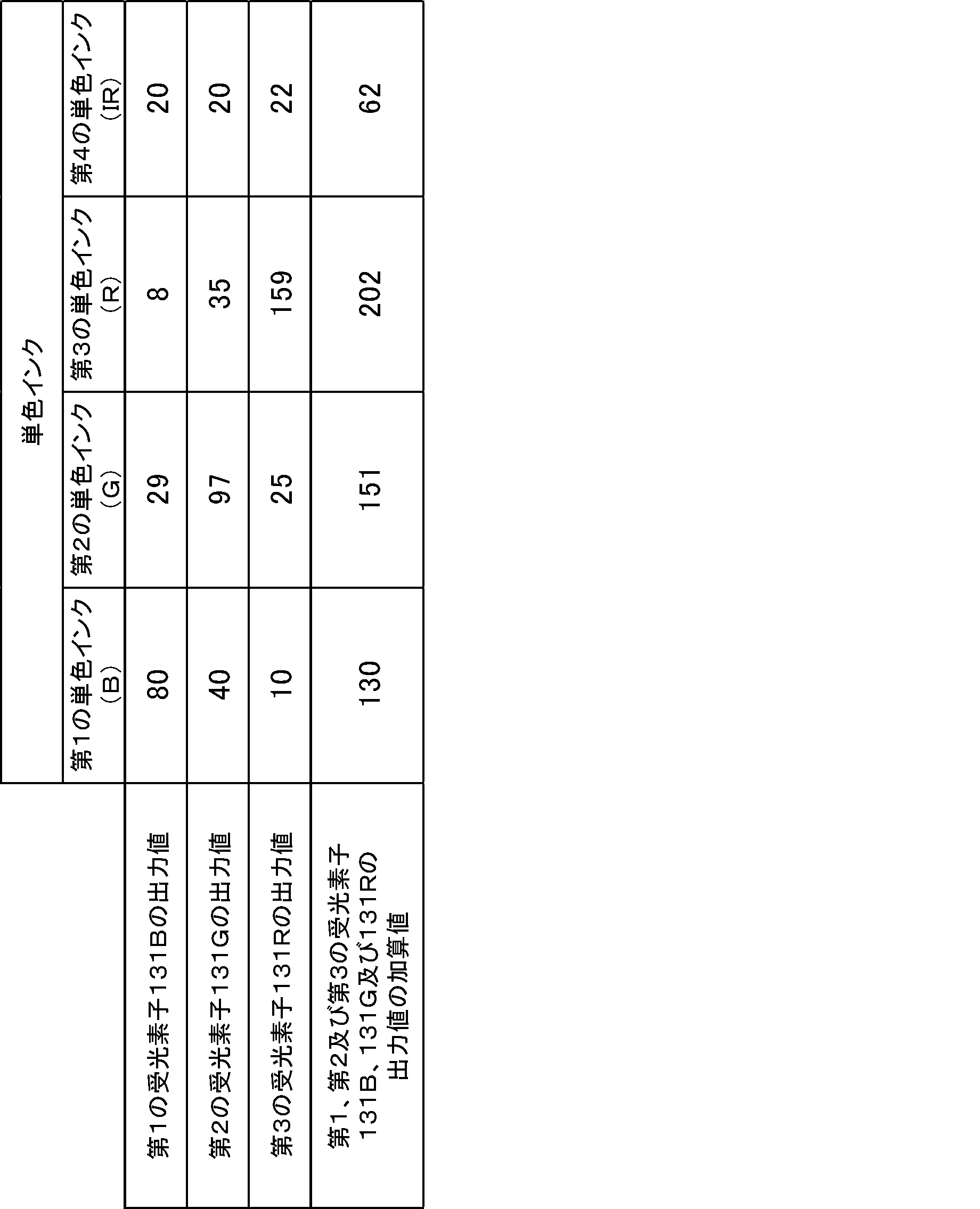
ここで、赤外光を選択的に受光する受光素子は受光部113に備わってないが、第1の受光素子131B、第2の受光素子131G及び第3の受光素子131Rのそれぞれが、赤外光を受光する。そこで、赤外光に関する出力値として、第1の受光素子131B、第2の受光素子131G及び第3の受光素子131Rの出力値(信号値)の加算値(合算値)を算出する。なお、燐光インクの種類毎に基準となる発光量を測定するときは、識別対象の紙幣から蛍光燐光検知信号及び燐光検知信号を取得するときと同様の条件にて、光源111から励起光を照射して燐光を検出する。
Here, although the
上記表1の結果より、各受光素子と単色インクとの間に下記(式1)の関係が成り立つ。 From the results in Table 1 above, the following relationship (Equation 1) holds true between each light receiving element and monochromatic ink.
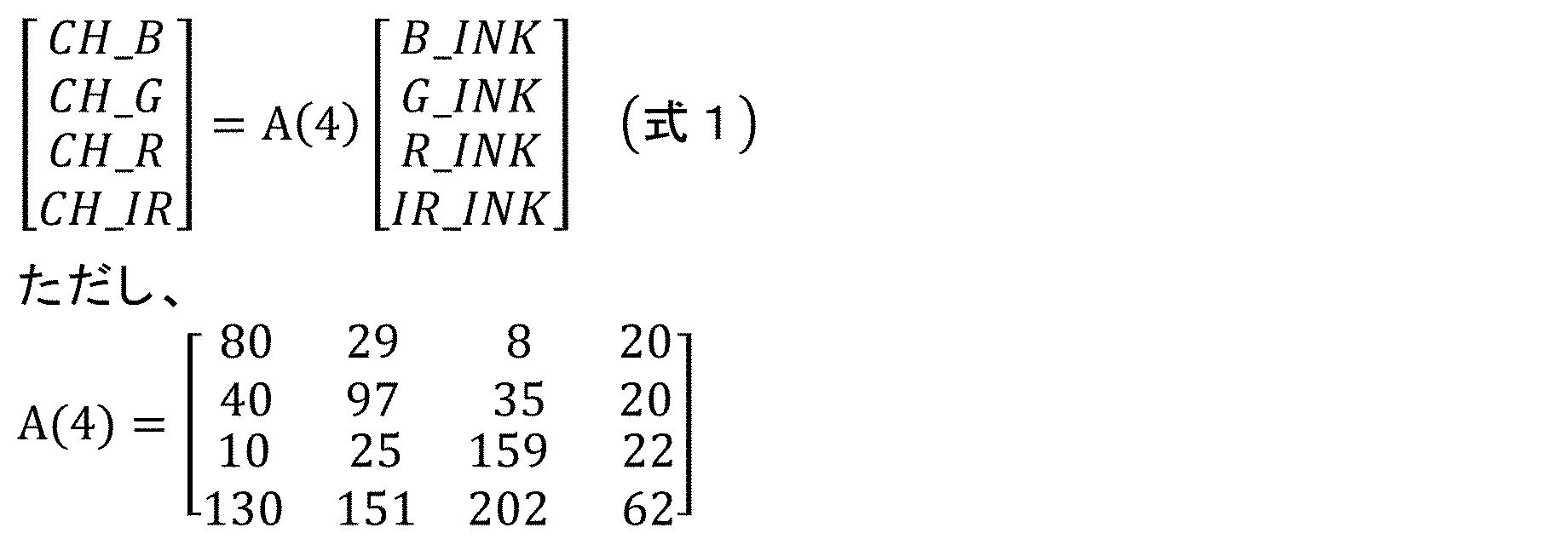
上記(式1)における行列A(4)を正規化すると、下記(式2)の関係が成り立つ。なお、下記(式2)では小数点第4位以下は切り捨てている。 When matrix A(4) in the above (Formula 1) is normalized, the following relationship (Formula 2) holds true. In addition, in the following (Formula 2), the fourth decimal place and below are rounded down.

上記(式2)を変形すると下記(式3)の関係が成り立つ。 When the above (Formula 2) is transformed, the following relationship (Formula 3) holds true.

ここで、(式2)及び(式3)におけるCH_B、CH_G、CH_R、CH_IR、B_INK、G_INK、R_INK、及びIR_INKは、(式1)と同じである。 Here, CH_B, CH_G, CH_R, CH_IR, B_INK, G_INK, R_INK, and IR_INK in (Formula 2) and (Formula 3) are the same as in (Formula 1).
補正部226にて、上記(式3)に示すように検出データ(各フェーズの推定燐光信号値及び燐光検知信号値)に対して逆行列B(4)-1を乗算する演算処理を行うことによりSO補正処理が行われる。
The
なお、識別対象の燐光インクの発光色が赤色、緑色、青色のいずれかである場合等では、このSO補正処理は省略することができる。 Note that in cases where the emitted light color of the phosphorescent ink to be identified is red, green, or blue, this SO correction process can be omitted.
算出部222は、図10を用いて説明したように、複数の蛍光燐光検知信号Sfpのうち、2番目以降の出力された蛍光燐光検知信号Sfpの信号値から、1番目に出力された蛍光燐光検知信号Sfpの信号値を減算することによって、2番目以降の出力された蛍光燐光検知信号Sfpにおいて推定燐光信号値を算出する。
As described using FIG. 10, the
具体的には、2番目の蛍光燐光信号値UV2から1番目の蛍光燐光信号値UV1を減算して、2番目の蛍光燐光検知信号Sfpにおける燐光成分(残光成分)ph1の信号値(以下、推定燐光信号値(UV2-UV1)とする)を算出する。また、3番目の蛍光燐光信号値UV3から1番目の蛍光燐光信号値UV1を減算して、3番目の蛍光燐光検知信号Sfpにおける燐光成分(残光成分)ph1及びph2の信号値(以下、推定燐光信号値(UV3-UV1)とする)を算出する。 Specifically, the first fluorescent phosphorescence signal value UV1 is subtracted from the second fluorescent phosphorescence signal value UV2 to obtain the signal value of the phosphorescence component (afterglow component) ph1 in the second fluorescent phosphorescence detection signal Sfp (hereinafter referred to as The estimated phosphorescence signal value (UV2-UV1) is calculated. In addition, the signal values of the phosphorescence components (afterglow components) ph1 and ph2 in the third fluorescence phosphorescence detection signal Sfp (hereinafter, estimated The phosphorescent signal value (UV3-UV1) is calculated.
補正部226は、同じセンサ制御条件で採取及び処理した基準媒体データより求めたSO(スペクトルオーバーラップ)補正係数を用いて、フェーズ毎に推定燐光信号値及び燐光検知信号値のSO補正を行う。具体的には、撮像部211からのR、G、B出力信号をSO補正することでR、G、IR信号を得る。これにより、上述のRGBの画素構成を有する撮像部211を用いて、赤色、緑色、赤外光の波長帯域でそれぞれ発光する燐光インクの色を判別することができる。
The
識別部223は、燐光有無判定値を算出する。具体的には、推定燐光信号値(UV2-UV1)と、推定燐光信号値(UV3-UV1)と、1番目に出力された燐光検知信号Spの信号値(以下、燐光信号値PHA1とする)と、2番目に出力された燐光検知信号Spの信号値(以下、燐光信号値PHA2とする)と、3番目に出力された燐光検知信号Spの信号値(以下、燐光信号値PHA3とする)と、を合算する。この燐光有無判定値の算出は、各R、G、IR信号について行う。
The
そして、識別部223は、各R、G、IR信号の燐光有無判定値を所定の閾値(R、G、IR信号に共通でもよい)と比較することによって、紙幣BNからの燐光発光の有無を判定する。すなわち、識別部223は、R、G、IR信号のいずれかの燐光有無判定値が上記閾値を超える場合、燐光発光が有ると判定し、R、G、IR信号のいずれの燐光有無判定値も上記閾値を超えない場合、燐光発光が無いと判定する。
Then, the
また、識別部223は、各R、G、IR信号の燐光有無判定値に基づいて、紙幣BNから発せられる燐光の色を判定する。具体的には、閾値を超える燐光有無判定値があれば、その信号の波長帯域に対応する色の燐光が紙幣BNから発せられたと判定する。
Further, the
なお、燐光インクの発光色が赤色、緑色又は青色(赤外光がない)の場合は、SO補正処理を行わず、燐光有無判定はR、G、B信号の各色で判定してもよい。 Note that when the emitted color of the phosphorescent ink is red, green, or blue (there is no infrared light), the SO correction process may not be performed, and the presence or absence of phosphorescence may be determined based on each color of the R, G, and B signals.
また、識別部223は、個々の紙幣BNの印刷濃度による時定数判定値のバラツキを補正するために、各推定燐光信号値と各燐光信号値とを規格化(正規化)する処理を行う。具体的には、推定燐光信号値(UV2-UV1)、推定燐光信号値(UV3-UV1)、燐光信号値PHA1、燐光信号値PHA2及び燐光信号値PHA3をそれぞれ燐光信号値PHA1で除算する。
Further, the
なお、規格化に使用する信号値は、燐光信号値PHA1に特に限定されず、他の信号値であってもよい。 Note that the signal value used for standardization is not particularly limited to the phosphorescence signal value PHA1, and may be any other signal value.
また、識別部223は、時定数判定値τを算出する。具体的には、時定数判定値τは、推定燐光信号値(UV2-UV1)及び燐光信号値PHA1から算出され、下記(式4)から算出される。
τ=1-(UV2-UV1)/PHA1 (式4)
The
τ=1-(UV2-UV1)/PHA1 (Formula 4)
なお、時定数判定値τは、上記(式4)で算出されるものに限定されず、例えば、下記(式5)から算出されたものであってもよい。
τ=(UV2-UV1)/PHA1 (式5)
Note that the time constant determination value τ is not limited to that calculated using the above (Formula 4), but may be calculated using the following (Formula 5), for example.
τ=(UV2-UV1)/PHA1 (Formula 5)
いずれの場合も時定数判定値τは、紙幣BNに設けられる燐光インクの時定数を反映した値となる。すなわち、燐光インクの時定数が大きくなるにしたがって、時定数判定値τは大きく、又は小さくなる。より具体的には、燐光インクの時定数が大きくなると、上記(式4)のτは大きくなり、上記(式5)のτは小さくなる。 In either case, the time constant determination value τ is a value that reflects the time constant of the phosphorescent ink provided on the banknote BN. That is, as the time constant of the phosphorescent ink becomes larger, the time constant determination value τ becomes larger or smaller. More specifically, when the time constant of the phosphorescent ink becomes large, τ in the above (Formula 4) becomes large, and τ in the above (Formula 5) becomes small.
そして、識別部223は、算出した時定数判定値τに基づいて紙幣BNに設けられた燐光インクを判別する。具体的には、時定数が互いに異なる各種の燐光インクの時定数判定値τを算出することによって予め判定テーブルを準備しておく。ここで、判定テーブルには、燐光インク毎に時定数判定値τの数値範囲が定義されている。そして、識別部223が、算出した時定数判定値τを判定テーブルと比較することによって、時定数判定値τが該当する燐光インクを特定する。
The
図18に、4種の燐光インクA~Dから実際に得られた各フェーズにおける推定燐光信号値及び燐光信号値(いずれもOS補正及びオフセット除去後)を示す。ここで、4種の燐光インクA~Dの時定数は、
燐光インクA<燐光インクB<燐光インクC<燐光インクD
の順に大きくなっている。
FIG. 18 shows estimated phosphorescent signal values and phosphorescent signal values (both after OS correction and offset removal) in each phase actually obtained from four types of phosphorescent inks A to D. Here, the time constants of the four types of phosphorescent inks A to D are:
Phosphorescent ink A<phosphorescent ink B<phosphorescent ink C<phosphorescent ink D
are increasing in the order of
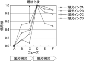
また、図19に、図18に示した各信号値を燐光インク毎にフェーズDの燐光信号値PHA1(1番目に出力された燐光検知信号Spの信号値)で規格化した結果を示す。図19に示された矢印の大きさが、上記(式4)から算出される時定数判定値τに対応している。そのため、図19で示されるように、燐光インク毎に得られた時定数判定値τは、4種の燐光インクA~Dの時定数と同じ大小関係となる。すなわち、時定数判定値τを用いて時定数による燐光インクの判別が可能であることが分かる。 Further, FIG. 19 shows the result of normalizing each signal value shown in FIG. 18 by the phosphorescence signal value PHA1 of phase D (the signal value of the first output phosphorescence detection signal Sp) for each phosphorescent ink. The size of the arrow shown in FIG. 19 corresponds to the time constant determination value τ calculated from the above (Formula 4). Therefore, as shown in FIG. 19, the time constant determination value τ obtained for each phosphorescent ink has the same magnitude relationship as the time constants of the four types of phosphorescent inks A to D. That is, it can be seen that the phosphorescent ink can be determined based on the time constant using the time constant determination value τ.
更に、上記4種の燐光インクA~Dから実際に得られた各フェーズにおける推定燐光信号値及び燐光信号値(いずれもOS補正及びオフセット除去後)を用いて各R、G、IR信号について燐光有無判定値の算出したところ、いずれのインクも判定マージンをもって有無を判定することができた。すなわち、各燐光インクについて、対応する色の信号による燐光有無判定値は所定の数値範囲を超える一方で、他の色の信号による燐光有無判定値は当該数値範囲を下回る結果が得られた。例えば、燐光インクAについて、G信号による燐光有無判定値は所定の数値範囲を超える一方で、R、IR信号による燐光有無判定値は当該数値範囲を下回る結果が得られた。 Furthermore, using the estimated phosphorescent signal values and phosphorescent signal values (both after OS correction and offset removal) in each phase actually obtained from the above four types of phosphorescent inks A to D, phosphorescence was calculated for each R, G, and IR signal. When the presence/absence determination value was calculated, the presence/absence of each ink could be determined with a determination margin. That is, for each phosphorescent ink, the phosphorescence presence/absence determination value based on the corresponding color signal exceeded a predetermined numerical range, while the phosphorescence presence/absence determination value based on other color signals fell below the numerical range. For example, for phosphorescent ink A, the phosphorescence presence/absence determination value based on the G signal exceeds a predetermined numerical range, while the phosphorescence presence/absence determination value based on the R and IR signals falls below the numerical range.
識別部223は、金種、真偽、正損等を識別するために、上述の燐光の有無やその発光色、燐光インク(燐光体)の判定結果を利用する。例えば、識別部223は、上述の燐光に係る判定結果に基づいて真偽を識別する。
The
次に、図20を用いて、本実施形態に係る紙葉類識別装置200の燐光判定に係る動作について説明する。
Next, the operation related to phosphorescence determination of the paper
図20に示すように、まず、制御部220が、撮像部211から、R、G、B出力信号毎に、紙幣BNのA面及びB面それぞれの蛍光燐光検知信号及び燐光検知信号を取得する(ステップS21)。
As shown in FIG. 20, first, the
次に、算出部222が、R、G、B信号毎に、2番目及び3番目の蛍光燐光検知信号Sfpにおいて推定燐光信号値を算出する(ステップS22)。
Next, the
次に、補正部226が、フェーズ毎に推定燐光信号値及び燐光検知信号値のSO補正を行い、R、G、IR信号に変換する(ステップS23)。
Next, the
次に、識別部223が、R、G、IR信号毎に、燐光有無判定値を算出する(ステップS24)。
Next, the
次に、識別部223が、燐光有無判定値に基づいて、R、G、IR信号毎に紙幣BNからの燐光発光の有無を判定するとともに、紙幣BNから発せられる燐光の色(R、G又はIR)を判定する(ステップS25)。
Next, the
次に、識別部223が、ステップS25においてR、G、IR信号のうち燐光発光が有ると判定された信号について、各推定燐光信号値と各燐光信号値とを燐光信号値PHA1で除算して規格化する(ステップS26)。
Next, the
次に、識別部223が、ステップS26で規格化された信号値から、例えば上記(式4)に基づき時定数判定値τを算出する(ステップS27)。
Next, the
その後、識別部223が、時定数判定値τに基づいて紙幣BNに設けられた燐光インクを判別し(ステップS28)、紙葉類識別装置200の動作が終了する。
Thereafter, the
次に、図21を用いて、本実施形態の変形例について説明する。 Next, a modification of this embodiment will be described using FIG. 21.
図21に示すように、複数の点灯期間の前に、1番目の点灯期間よりも短く、かつ紙幣から実質的に燐光が発しない短期間、光源から励起光としての紫外光を照射してもよい。そして、この短期間に紙幣から発せられる光を受光部で受光し、受光部から蛍光検知信号Sfを出力してもよい。蛍光は時定数が極めて短く、短時間の受光でも信号を得られるため、この短期間で受光される光は、ほぼ蛍光成分のみとなる。 As shown in FIG. 21, even if ultraviolet light as excitation light is irradiated from a light source for a short period of time, which is shorter than the first lighting period and during which phosphorescence is not substantially emitted from the banknote, before the plurality of lighting periods. good. Then, the light emitted from the banknote during this short period of time may be received by the light receiving section, and the fluorescence detection signal Sf may be output from the light receiving section. Fluorescence has an extremely short time constant and a signal can be obtained even after receiving light for a short period of time, so the light received during this short period of time consists almost only of fluorescent components.
そこで、1番目の点灯期間の発光時間をTとし、短期間の発光時間をtとすると、蛍光検知信号Sfの信号値を(T/t)倍した値は、1番目の蛍光燐光検知信号Sfpに占める蛍光成分の信号値に等しくなる。したがって、1番目の蛍光燐光検知信号Sfpの信号値から、蛍光検知信号Sfの信号値を(T/t)倍した値を減算することによって、1番目の蛍光燐光検知信号Sfpにおいて、推定燐光信号値として、励起光の照射に応じて増加する燐光成分p1による信号値を算出(推定)できる。 Therefore, if the light emission time in the first lighting period is T and the short-term light emission time is t, the value obtained by multiplying the signal value of the fluorescence detection signal Sf by (T/t) is the value of the first fluorescence phosphorescence detection signal Sfp. It is equal to the signal value of the fluorescent component that occupies Therefore, by subtracting the value obtained by multiplying the signal value of the fluorescence detection signal Sf by (T/t) from the signal value of the first fluorescence phosphorescence detection signal Sfp, the estimated phosphorescence signal is obtained in the first fluorescence phosphorescence detection signal Sfp. As a value, it is possible to calculate (estimate) a signal value due to the phosphorescent component p1 that increases in accordance with the irradiation of the excitation light.
なお、発光時間t(短期間)は、1番目の点灯期間よりも短く、かつ紙幣から実質的に燐光が発しない期間であれば適宜設定可能であるが、発光時間T(1番目の点灯期間)の1/10~1/20程度であってもよい。 Note that the light emitting time t (short period) can be set as appropriate as long as it is shorter than the first lighting period and during which phosphorescence is not substantially emitted from the banknote; ) may be about 1/10 to 1/20 of that.
この推定燐光信号値は、上述の燐光の有無等の判定処理に用いることができる。例えば、上述の燐光有無判定値に更にこの推定燐光信号値を合算して用いてもよい。 This estimated phosphorescence signal value can be used in the above-described process of determining the presence or absence of phosphorescence. For example, this estimated phosphorescence signal value may be added to the phosphorescence presence/absence determination value described above.
(実施形態5)
本実施形態では、実施形態3の紙葉類識別装置のより具体的な例について説明する。また、本実施形態は、算出部による推定燐光信号値の算出方法が異なる点を除いて、実施形態4と実質的に同じである。まず、本実施形態の概要について説明する。
(Embodiment 5)
In this embodiment, a more specific example of the paper sheet identification device of
図22に示すように、紙葉類識別装置200により搬送される紙幣BNが撮像部211の上部ユニット110及び下部ユニット120の間を通過する際に励起用の光源(図示せず)を周期点灯した場合、照射幅があるため、図23に示すように測定位置に達する前に励起が繰り返される。そして、受光部(図示せず)の測定位置での結果は、図23の右側破線部となる。また、励起時に含まれる特徴は、図24に示されるように、3つの成分が含まれている。すなわち、蛍光インク(紙による蛍光成分でもよい)の蛍光成分Fと、燐光インクの減衰燐光成分αと、燐光インクの励起燐光成分βと、前回照射の励起による燐光インクの残光成分PHnとである。そして、本実施形態では、この蛍光成分Fに基づくと推定される推定蛍光信号値を算出し、この推定蛍光信号値を用いて残光成分PHnに基づくと推定される信号値、すなわち推定残光信号値を算出する。以下、この方法について詳述する。
As shown in FIG. 22, when the banknote BN conveyed by the paper
なお、実施形態4においても、図23に示したように測定位置に達する前に励起が繰り返されてもよく、その場合であっても実施形態4の算出方法により推定燐光信号値を算出することができる。 Note that in the fourth embodiment as well, excitation may be repeated before reaching the measurement position as shown in FIG. 23, and even in that case, the estimated phosphorescence signal value may be calculated by the calculation method of the fourth embodiment. Can be done.
まず、前提として、上述のように、発光するインクの特徴として、蛍光特徴及び燐光特徴がある。蛍光特徴は、励起光を照射したときのみ発光し、照射時間変化に対して発光量は変わらない。燐光特徴は、励起光を照射したときに、発光量が増加し、照射時間に対して増変化する。また、燐光特徴は、励起光を止めた場合も発光し、照射を止めてからの時間変化に対して発光量も減衰する特徴がある。 First, as a premise, as described above, the characteristics of the ink that emit light include fluorescent characteristics and phosphorescent characteristics. Fluorescence is characterized by emitting light only when it is irradiated with excitation light, and the amount of light emitted does not change as the irradiation time changes. The phosphorescence characteristic is that when irradiated with excitation light, the amount of emitted light increases and changes with the irradiation time. In addition, the phosphorescence characteristic is that it emits light even when the excitation light is stopped, and the amount of light emission also decreases with respect to time changes after the irradiation is stopped.
説明を容易にするためにまずは、燐光特徴のみに絞って説明する。 To make the explanation easier, we will first focus on the phosphorescence characteristics.
燐光特徴は、励起光の照射中の測定結果(立ち上がり)及び励起光の照射後の測定結果(立ち下がり)ともに線形の増減であると仮定する(図25及び図26参照)。例えば、時定数τが400μsの場合、立ち上がりの点灯時間=60μsとすると、図25のように、線形の増加特徴として仮定できる。 It is assumed that the phosphorescence characteristic increases and decreases linearly in both the measurement results during excitation light irradiation (rise) and the measurement results after excitation light irradiation (fall) (see FIGS. 25 and 26). For example, if the time constant τ is 400 μs and the rising lighting time is 60 μs, a linear increasing feature can be assumed as shown in FIG.
線形とした場合、励起光照射中の受光積算量を積算区間A:FL_1、積算区間B:FL_2、積算区間C:FL_3とする(図27参照)。3つの積算時間(測定時間)が同じであれば、
FL_2-FL_1=FL_1×2 又は 3×FL_1=FL_2
との計算が成り立つことがわかる(図28参照)。
In the case of linearity, the integrated amount of received light during excitation light irradiation is set to integration section A: FL_1, integration section B: FL_2, and integration section C: FL_3 (see FIG. 27). If the three integrated times (measurement times) are the same,
FL_2-FL_1=FL_1×2 or 3×FL_1=FL_2
It can be seen that the calculation holds true (see FIG. 28).
また、線形と定義すれば、1回目の露光時(例えば0~20μs)の積算量Aと、2回目の露光時(例えば20~40μs)積算量Bとの関係は、
B=3×A
と定義できる。
Furthermore, if defined as linear, the relationship between the integrated amount A during the first exposure (for example, 0 to 20 μs) and the integrated amount B during the second exposure (for example, 20 to 40 μs) is as follows.
B=3×A
It can be defined as
上記結果より、励起時の燐光特徴による発光量の増加量βは、
β=(FL_2-FL_1)/2
として定義できる(図29参照)。
From the above results, the amount of increase in luminescence amount β due to the phosphorescent feature during excitation is
β=(FL_2-FL_1)/2
(See Figure 29).
なお、βは、FL_2とFL_3から算出してもよい。この場合、βは、
β=(FL_3-FL_2)/2
と定義できる。
Note that β may be calculated from FL_2 and FL_3. In this case, β is
β=(FL_3-FL_2)/2
It can be defined as
次に、励起光消灯後の燐光発光量の減少量について、図30のように、積算区間D:PH_1、積算区間E:PH_2、積算区間F:PH_3を測定する。ただし、積算時間はPH_1、PH_2、PH_3ともに同じである。 Next, as shown in FIG. 30, the amount of decrease in the amount of phosphorescent light emission after the excitation light is turned off is measured in the integration section D: PH_1, the integration section E: PH_2, and the integration section F: PH_3. However, the cumulative time is the same for PH_1, PH_2, and PH_3.
3データの場合(PH_1,2,3)を想定し、立下りともに線形で減少すると仮定する。すると、立ち上がり特性と同じく発光量の減衰量αは、
α=(PH_1-PH_2)/2
と定義できる(図31参照)。
Assuming a case of 3 data (PH_1, 2, 3), it is assumed that both falling edges decrease linearly. Then, as with the rise characteristic, the attenuation amount α of the light emission amount is
α=(PH_1-PH_2)/2
It can be defined as (see Figure 31).
そして、PH_1とαより、仮想の積算区間PH_0を、
PH_0=PH_1+2α
より算出する(図32及び図33参照)。
Then, from PH_1 and α, the virtual integration interval PH_0 is
PH_0=PH_1+2α
(See FIGS. 32 and 33).
なお、αは、PH_2とPH_3から算出してもよい。この場合、αは、
α=(PH_3-PH_2)/2
と定義できる。
Note that α may be calculated from PH_2 and PH_3. In this case, α is
α=(PH_3-PH_2)/2
It can be defined as
図34に示すように、PH_0は、
PH_0=γ+SIM_FL_3
として表現でき、SIM_FL_3から励起中の燐光特徴の増加成分が得られる。
As shown in FIG. 34, PH_0 is
PH_0=γ+SIM_FL_3
The increasing component of the phosphorescence feature during excitation is obtained from SIM_FL_3.
ここで、γをαとβを用いて表現すると、
γ=α+β
となる。
Here, if we express γ using α and β, we get
γ=α+β
becomes.
そのため、SIM_FL_3は、
SIM_FL_3=PH_0-γ
から算出できる(図35参照)。
Therefore, SIM_FL_3 is
SIM_FL_3=PH_0-γ
It can be calculated from (see Figure 35).
よって、励起中の燐光特徴の増加成分であるFL_3は、
FL_3≒SIM_FL_3
である。
Therefore, FL_3, which is the increasing component of the phosphorescent feature during excitation, is
FL_3≒SIM_FL_3
It is.
次に、図36に示すように、燐光インクと蛍光インクが混合した場合、又は、燐光インクの印刷した紙が蛍光発光した場合を想定する。この場合、励起中にのみ蛍光成分Fが追加される。 Next, as shown in FIG. 36, assume that phosphorescent ink and fluorescent ink are mixed, or that paper printed with phosphorescent ink emits fluorescence. In this case, the fluorescent component F is added only during excitation.
この場合、βは、
β={(FL_2+F)-(FL_1+F)}/2
=(FL_2-FL_1)/2
となり、βは蛍光発光量に左右されずに得られることが分かる。
In this case, β is
β={(FL_2+F)-(FL_1+F)}/2
=(FL_2-FL_1)/2
It can be seen that β can be obtained without being influenced by the amount of fluorescence emission.
α及びPH_0は、
α=(PH_1-PH_2)/2
PH_0 PH_1+2α
となり、α及びPH_0は蛍光発光量に左右されずに得られることがわかる。
α and PH_0 are
α=(PH_1-PH_2)/2
PH_0 PH_1+2α
It can be seen that α and PH_0 can be obtained without being influenced by the amount of fluorescent light emission.
また、γ=α+βより、
SIM_FL_3=PH_0-γ
として、SIM_FL_3が算出される。
よって積算区間Cに含まれる蛍光成分Fは、
F=FL_3-SIM_FL_3
より算出することができる。
Also, from γ=α+β,
SIM_FL_3=PH_0-γ
, SIM_FL_3 is calculated.
Therefore, the fluorescence component F included in the integration interval C is
F=FL_3-SIM_FL_3
It can be calculated from
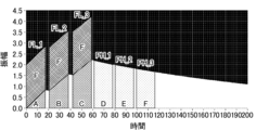
最後に、図37及び図38に示すように、蛍光特徴及び燐光特徴がある場合であって複数サイクルにわたる励起後について例を示す。なお、図38中の太い破線で囲まれた領域が測定される量、すなわち信号値となる。 Finally, an example is given for the case where there are fluorescent and phosphorescent features and after multiple cycles of excitation, as shown in FIGS. 37 and 38. Note that the area surrounded by the thick broken line in FIG. 38 is the measured quantity, that is, the signal value.
まず、励起光消灯後の2データ(PH1_1,2)より、
α=(PH1_1-PH1_2)/2
と定義できる。
First, from the two data (PH1_1, 2) after the excitation light is turned off,
α=(PH1_1-PH1_2)/2
It can be defined as
なお、励起光消灯後の別の2データ(PH1_2,3)より、
α=(PH1_2-PH1_3)/2
と定義してもよい。
In addition, from two other data (PH1_2, 3) after the excitation light was turned off,
α=(PH1_2-PH1_3)/2
It may be defined as
PH1_1とαより、
PH1_0=PH1_1+2α
を算出する。
From PH1_1 and α,
PH1_0=PH1_1+2α
Calculate.
励起光点灯中の2つのデータ(FL1_1,2)より、
β=(FL1_2-FL1_1)/2
が算出できる。
From the two data (FL1_1, 2) while the excitation light is on,
β=(FL1_2-FL1_1)/2
can be calculated.
なお、励起光点灯中の別の2データ(FL1_2,3)より、
β=(FL1_3-FL1_2)/2
を算出してもよい。
In addition, from two other data (FL1_2, 3) when the excitation light is on,
β=(FL1_3-FL1_2)/2
may be calculated.
更に、
SIM_FL1_3=PH1_0-(α+β)
からSIM_FL1_3を算出でき、含まれている蛍光量Fは、
F=FL1_3-SIM_FL1_3
として算出できる(図39参照)。この蛍光量Fが推定蛍光信号値となる。
Furthermore,
SIM_FL1_3=PH1_0-(α+β)
SIM_FL1_3 can be calculated from, and the included fluorescence amount F is
F=FL1_3-SIM_FL1_3
(See Figure 39). This fluorescence amount F becomes the estimated fluorescence signal value.
そして、
PHn=FL1_1-F-α-β
からPHnが得られる(図38参照)。なお、Fは蛍光量であるので一定である。このPHnが推定残光信号値となる。
and,
PHn=FL1_1-F-α-β
PHn is obtained from (see FIG. 38). Note that since F is the amount of fluorescence, it is constant. This PHn becomes the estimated afterglow signal value.
例えば、このPHnとPH1_1を減衰特徴として利用することで燐光特徴による真偽判別として利用できる。 For example, by using PHn and PH1_1 as attenuation features, it is possible to use phosphorescent features to determine authenticity.
ここで、上記実施形態1~5において、識別対象の燐光体の時定数の範囲について説明する。 Here, in the first to fifth embodiments described above, the range of the time constant of the phosphor to be identified will be explained.
図40の左に示すように、上記実施形態1~5では、励起光を照射すると燐光インク等の燐光体が発する燐光の強度が線形的に増加すると仮定した。そのため、時刻t0からt1までの燐光量(受光積算量)をmとすると、時刻t1からt2までの燐光量(受光積算量)nはm×3、時刻t2からt3までの燐光量(受光積算量)lはm×5、とそれぞれ表される。なお、この関係が成立するのは、t0=0、t1=T、t2=2T、t3=3Tを満たす場合である。すなわち、燐光量m、n、lの受光時間が同じ場合である。 As shown on the left side of FIG. 40, in the first to fifth embodiments described above, it is assumed that the intensity of phosphorescence emitted by a phosphor such as a phosphorescent ink increases linearly when the excitation light is irradiated. Therefore, if the amount of phosphorescence (integrated amount of received light) from time t0 to t1 is m, the amount of phosphorescence (integrated amount of received light) from time t1 to t2 is m×3, and the amount of phosphorescence (integrated amount of received light) from time t2 to t3 is Quantity) l is expressed as m×5, respectively. Note that this relationship is established when t0=0, t1=T, t2=2T, and t3=3T. That is, this is a case where the light reception times of the phosphorescence amounts m, n, and l are the same.
しかしながら、厳密には、図40の右に示すように、燐光の強度は、指数関数的に増加し、やがて飽和し、時刻t0からt1までの燐光量(受光積算量)M、時刻t1からt2までの燐光量(受光積算量)N、時刻t2からt3までの燐光量(受光積算量)Lは、それぞれ図中に示した式で表される。各式中、Aは定数を表し、τは時定数を表す。 However, strictly speaking, as shown on the right side of FIG. 40, the intensity of phosphorescence increases exponentially and eventually becomes saturated. The amount of phosphorescence (integrated amount of received light) N from time t2 to time t3 (integrated amount of received light) L is expressed by the formula shown in the figure. In each formula, A represents a constant, and τ represents a time constant.
このとき、下記(式6)が満たされれば上記仮定が成立すると考えられる。以下、この誤差範囲を定義する。 At this time, it is considered that the above assumption is established if the following (Formula 6) is satisfied. This error range will be defined below.

コンタクトイメージセンサ(以下、CISと略記する)の一般的なSN比は、40dB程度であるため、CISが8bitの場合、255/100=2.5digitのノイズ成分があると仮定できる。上記ノイズと同等の出力変動に対して誤差を許容するとした場合、燐光量Mは、下記式(式7)で表される。ただし、t0=0、t1=T、t2=2T、t3=3Tとする。 Since the general SN ratio of a contact image sensor (hereinafter abbreviated as CIS) is about 40 dB, it can be assumed that when CIS is 8 bits, there is a noise component of 255/100=2.5 digits. If an error is allowed for the output fluctuation equivalent to the above-mentioned noise, the amount of phosphorescence M is expressed by the following formula (Formula 7). However, it is assumed that t0=0, t1=T, t2=2T, and t3=3T.

また、下記式(式8)で表される燐光量Lを下記(式9)に変形すると、上記(式7)と、この(式9)と、燐光量Mを示す下記(式10)とから下記(式11)で表される燐光量Lが算出される。 Furthermore, when the phosphorescence amount L expressed by the following formula (Formula 8) is transformed into the following (Formula 9), the above (Formula 7), this (Formula 9), and the following (Formula 10) representing the phosphorescence amount M are obtained. The amount of phosphorescence L expressed by the following (Equation 11) is calculated from.


ここで、燐光インクを含んだ蛍光発光する媒体(紙幣)の蛍光量と燐光量の関係について説明する。本発明者らによる測定の結果、励起光源点灯直後の発光量を蛍光インクの発光量とし、所定時間経過後(ここでは時間60μs経過後)の発光量から蛍光インクと燐光インクの発光比率を算出すると、蛍光量:燐光量の比率は、およそ0.3:0.7から0.6:0.4の範囲という結果であった。 Here, the relationship between the amount of fluorescence and the amount of phosphorescence of a medium (banknote) that emits fluorescence and contains phosphorescent ink will be explained. As a result of measurements by the present inventors, the luminescence amount of the fluorescent ink is taken as the luminescence amount immediately after the excitation light source is turned on, and the luminescence ratio of the fluorescent ink and the phosphorescent ink is calculated from the luminescence amount after a predetermined period of time (in this case, after 60 μs has elapsed). The result was that the ratio of the amount of fluorescence to the amount of phosphorescence was approximately in the range of 0.3:0.7 to 0.6:0.4.
したがって、上記媒体による発光は、下記(式12)で表される。
蛍光量:燐光量=FO:(1-FO) (式12)
ただし、FOは1以下とする。
Therefore, the light emission by the medium is expressed by the following (Equation 12).
Fluorescence amount: Phosphorescence amount = FO: (1-FO) (Formula 12)
However, FO shall be 1 or less.
また、ここではセンサは8bitのCISを想定しているため、出力値が255以上あれば、誤差の影響なく燐光及び蛍光を検知ができる。したがって、センサの受光量、すなわち燐光量Lと蛍光量Fは、下記(式13)で表すことができる。
L+F=255 (式13)
Furthermore, since the sensor here is assumed to be an 8-bit CIS, if the output value is 255 or more, phosphorescence and fluorescence can be detected without being affected by errors. Therefore, the amount of light received by the sensor, that is, the amount of phosphorescence L and the amount of fluorescence F can be expressed by the following (Equation 13).
L+F=255 (Formula 13)
また、上記(式12)から下記(式14)が成立し、これを上記(式13)に代入すると、下記(式15)が得られる。 Further, the following (Formula 14) is established from the above (Formula 12), and when this is substituted into the above (Formula 13), the following (Formula 15) is obtained.


この(式15)を変形すると下記(式16)が得られる。 By transforming this (Formula 15), the following (Formula 16) is obtained.

この(式16)と、上記(式11)とにより、時間Tの変動に対する、時定数と蛍光量比率の関係を計算した結果を下記表2に示す。 Table 2 below shows the results of calculating the relationship between the time constant and the fluorescence amount ratio with respect to fluctuations in time T using this (Equation 16) and the above (Equation 11).

蛍光量比率は調査した結果、上述のように30%~60%程度であるが、表2には、10%から90%の結果を示している。これらの時定数より大きければ上記CISにて誤差なく燐光及び蛍光を検知することができる。 As a result of investigation, the fluorescence amount ratio is about 30% to 60% as mentioned above, and Table 2 shows the results from 10% to 90%. If the time constants are larger than these, the CIS can detect phosphorescence and fluorescence without error.
この結果より、蛍光量比率が30%~60%程度の一般的な媒体(紙幣)であれば、その時定数は120μs以上であってもよいし、150μm以上であってもよい。なお、時定数の上限は特に限定されないが、例えば、10ms以下であってもよいし、7ms以下であってもよい。 From this result, if it is a general medium (banknote) with a fluorescence amount ratio of about 30% to 60%, the time constant may be 120 μs or more or 150 μm or more. Note that the upper limit of the time constant is not particularly limited, but may be, for example, 10 ms or less, or 7 ms or less.
また、表2より、時間Tに対する時定数τの比率(τ/T)を計算した結果を下記表3に示す。 Further, from Table 2, the ratio of the time constant τ to the time T (τ/T) was calculated and the results are shown in Table 3 below.
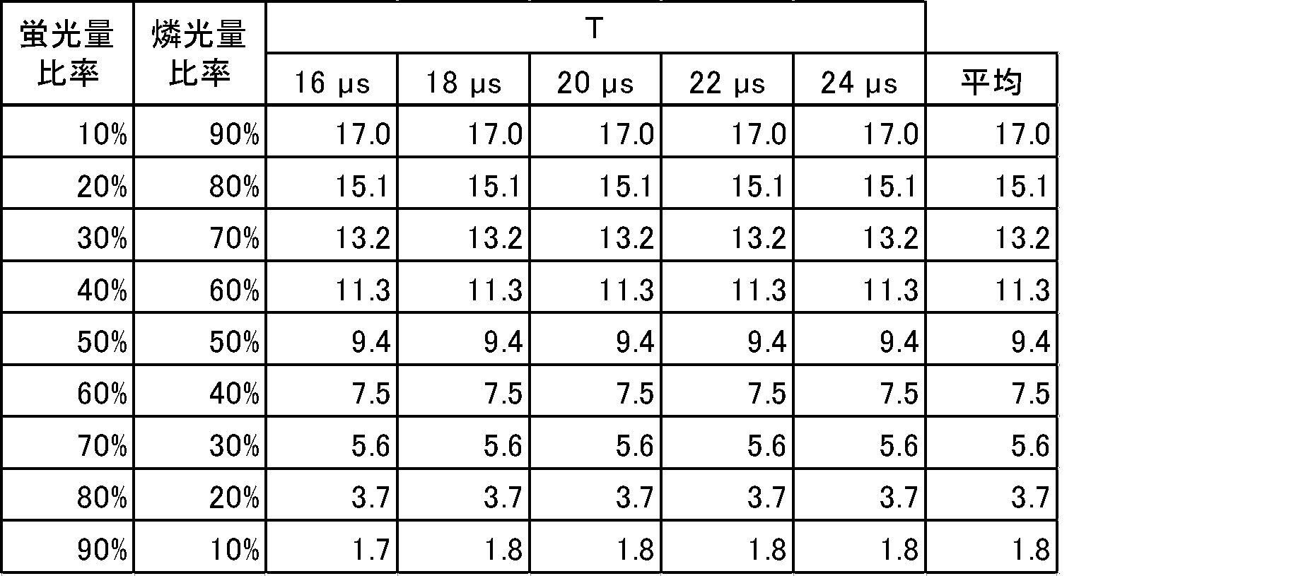
この結果より、時定数は、蛍光量比率が30%の時はT×13.5(μs)以上、蛍光量比率が60%の時はT×7.5(μs)以上であれば、上記CISにて誤差なく燐光及び蛍光を検知することができる。すなわち、蛍光量比率が30%~60%程度の一般的な媒体(紙幣)であれば、その時定数はT×7.5(μs)以上であってもよい。 From this result, if the time constant is T x 13.5 (μs) or more when the fluorescence amount ratio is 30%, and T x 7.5 (μs) or more when the fluorescence amount ratio is 60%, then Phosphorescence and fluorescence can be detected with CIS without error. That is, if it is a general medium (banknote) with a fluorescence amount ratio of about 30% to 60%, the time constant may be T×7.5 (μs) or more.
(変形例1)
上記実施形態1~5では、励起光が照射される際、他の種類の光は照射されないが、励起光照射による反射光、透過光、蛍光及び燐光が他の特徴量検出に対して影響を及ぼさなければ、反射画像及び/又は透過画像を取得するために照射する光と同時に、励起光を照射してもよい。
(Modification 1)
In
(変形例2)
上記実施形態4及び5では、白色光を照射して、青色光、緑色光及び赤色光を、それぞれ受光素子133B、緑色の受光素子133G及び赤色の受光素子133Rの3種類の受光素子で同時に受光するが、上記実施形態1~5では、青色光、緑色光及び赤色光を交互に点灯させ、紙幣から到達する光を1種類の受光素子で受光してもよい。
(Modification 2)
In the
(変形例3)
上記実施形態1~5では、同じ1サイクル中における1以上の点灯期間及び1以上の消灯期間に関する1以上の蛍光燐光検知信号及び1以上の燐光検知信号を処理する場合について説明したが、上述の処理が行われる1以上の蛍光燐光検知信号及び1以上の燐光検知信号は、互いに異なる複数のサイクルで受光され光に基づくものであってもよい。ここで、複数のサイクルは、連続する複数(例えば2つ)のサイクルであってもよい。
(Modification 3)
In the first to fifth embodiments described above, a case has been described in which one or more fluorescent phosphorescence detection signals and one or more phosphorescence detection signals regarding one or more lighting periods and one or more non-lighting periods in the same one cycle are processed. The one or more fluorescent phosphorescence detection signals and the one or more phosphorescence detection signals that are processed may be light-based and received in different cycles. Here, the plurality of cycles may be a plurality of consecutive (for example, two) cycles.
以上、図面を参照しながら実施形態を説明したが、本開示は、上記実施形態に限定されるものではない。また、各実施形態の構成は、本開示の要旨を逸脱しない範囲において適宜組み合わされてもよいし、変更されてもよい。 Although the embodiments have been described above with reference to the drawings, the present disclosure is not limited to the above embodiments. Furthermore, the configurations of each embodiment may be combined or modified as appropriate without departing from the gist of the present disclosure.
以上のように、本開示は、燐光に基づき紙葉類を高精度に識別するのに有用な技術である。 As described above, the present disclosure is a technology useful for identifying paper sheets with high precision based on phosphorescence.
1、200:紙葉類識別装置
11、111、121、124:光源
13、113、123:受光部
20、220:制御部
21、221:光源制御部
22、222:算出部
23、223:識別部
110:上部ユニット
120:下部ユニット
112、122:集光レンズ
131B、131G、131R:受光素子
131GP:画素
210:検出部
211:撮像部
212:磁気検出部
213:厚み検出部
224:センサ制御部
225:画像生成部
226:補正部
230:記憶部
300:紙幣処理装置
301:ホッパ
302:リジェクト部
303:操作部
304:筐体
305:表示部
306a~306d:集積部
1310:光検出器
1311B、1311G、1311R:カラーレジスト
BN:紙幣
Sfp:蛍光燐光検知信号
Sp:燐光検知信号
Sf:蛍光検知信号
1, 200: Paper
Claims (11)
紙葉類に対して、励起光を照射する光源と、
前記励起光を点灯期間で照射し、かつ前記点灯期間後の消灯期間で消灯するように、前記光源を制御する光源制御部と、
前記点灯期間に前記紙葉類から発せられる光に基づく蛍光燐光検知信号を出力するとともに、前記消灯期間に前記紙葉類から発せられる光に基づく燐光検知信号を出力する受光部と、
前記蛍光燐光検知信号において、前記受光部が前記紙葉類から受光した燐光に基づく信号値と推定される推定燐光信号値を算出する算出部と、
前記推定燐光信号値に基づいて前記紙葉類の識別を行う識別部と、を備える
ことを特徴とする紙葉類識別装置。 A paper sheet identification device that detects fluorescence and phosphorescence emitted from paper sheets being conveyed,
a light source that irradiates excitation light onto paper sheets;
a light source control unit that controls the light source so that the excitation light is irradiated during a lighting period and is turned off during a non-lighting period after the lighting period;
a light receiving unit that outputs a fluorescent phosphorescence detection signal based on the light emitted from the paper sheet during the lighting period, and outputs a phosphorescence detection signal based on the light emitted from the paper sheet during the lights-out period;
a calculation unit that calculates an estimated phosphorescence signal value that is estimated to be a signal value based on phosphorescence received by the light receiving unit from the paper sheet in the fluorescent phosphorescence detection signal;
A paper sheet identification device comprising: an identification section that identifies the paper sheet based on the estimated phosphorescence signal value.
前記受光部は、前記複数の点灯期間に前記紙葉類から発せられる光に基づく複数の蛍光燐光検知信号を順次出力し、
前記算出部は、前記複数の蛍光燐光検知信号のうち、2番目以降の出力された蛍光燐光検知信号の信号値から、1番目に出力された蛍光燐光検知信号の信号値を減算することによって、前記2番目以降の出力された前記蛍光燐光検知信号において前記推定燐光信号値を算出する
ことを特徴とする請求項1記載の紙葉類識別装置。 The light source control unit controls the light source to emit the excitation light in a plurality of lighting periods,
The light receiving unit sequentially outputs a plurality of fluorescent phosphorescence detection signals based on light emitted from the paper sheet during the plurality of lighting periods,
The calculation unit subtracts the signal value of the first outputted fluorescent phosphorescence detection signal from the signal value of the second and subsequent outputted fluorescent phosphorescence detection signals among the plurality of fluorescent phosphorescence detection signals, The paper sheet identification device according to claim 1, wherein the estimated phosphorescence signal value is calculated in the second and subsequent outputted fluorescent phosphorescence detection signals.
前記受光部は、前記短期間に前記紙葉類から発せられる光に基づく蛍光検知信号を出力し、
前記1番目の点灯期間の時間をTとし、前記短期間の時間をtとしたとき、
前記算出部は、前記1番目に出力された前記蛍光燐光検知信号の前記信号値から、前記蛍光検知信号の信号値を(T/t)倍した値を減算することによって、前記1番目に出力された前記蛍光燐光検知信号において前記推定燐光信号値を算出する
ことを特徴とする請求項2記載の紙葉類識別装置。 Before the plurality of lighting periods, the light source control unit controls the excitation for a short period of time that is shorter than a first lighting period of the plurality of lighting periods and in which phosphorescence is not substantially emitted from the paper sheet. controlling the light source to emit light;
The light receiving unit outputs a fluorescence detection signal based on light emitted from the paper sheet during the short period of time,
When the time of the first lighting period is T and the time of the short period is t,
The calculation unit outputs the first output by subtracting a value obtained by multiplying the signal value of the fluorescence detection signal by (T/t) from the signal value of the first output fluorescence phosphorescence detection signal. 3. The paper sheet identification device according to claim 2, wherein the estimated phosphorescence signal value is calculated from the detected fluorescence phosphorescence detection signal.
前記受光部は、前記複数の点灯期間に前記紙葉類から発せられる光に基づく複数の蛍光燐光検知信号を順次出力するとともに、前記複数の消灯期間で前記紙葉類から発せられる光に基づく複数の燐光検知信号を順次出力し、
前記算出部は、前記複数の蛍光燐光検知信号及び前記複数の燐光検知信号に基づいて、前記複数の蛍光燐光検知信号において、前記受光部が前記紙葉類から受光した蛍光に基づく信号値と推定される推定蛍光信号値を算出する
ことを特徴とする請求項1記載の紙葉類識別装置。 The light source control unit controls the light source to emit the excitation light in a plurality of lighting periods, and to turn off the light in a plurality of turn-off periods after the plurality of lighting periods,
The light receiving unit sequentially outputs a plurality of fluorescent phosphorescence detection signals based on the light emitted from the paper sheet during the plurality of lighting periods, and outputs a plurality of fluorescent phosphorescence detection signals based on the light emitted from the paper sheet during the plurality of non-lighting periods. sequentially outputs phosphorescence detection signals,
The calculation unit estimates, based on the plurality of fluorescent phosphorescence detection signals and the plurality of phosphorescence detection signals, a signal value based on the fluorescence received by the light receiving unit from the paper sheet in the plurality of fluorescent phosphorescence detection signals. 2. The paper sheet identification device according to claim 1, wherein the paper sheet identification device calculates an estimated fluorescence signal value.
ことを特徴とする請求項4記載の紙葉類識別装置。 The calculation unit calculates the estimated phosphorescence signal value in the fluorescence phosphorescence detection signal by subtracting at least the estimated fluorescence signal value from at least one signal value of the plurality of fluorescence phosphorescence detection signals. The paper sheet identification device according to claim 4.
前記光源制御部は、前記複数の点灯期間及び前記複数の消灯期間を含む所定のサイクルを繰り返すように、前記光源を制御し、
前記算出部は、前記推定燐光信号値として、前記測定位置に到達する前に前記紙葉類に照射された前記励起光による燐光の残光成分に基づくものと推定される信号値を算出する
ことを特徴とする請求項4又は5記載の紙葉類識別装置。 The light source irradiates the excitation light to a region including at least a measurement position of the light receiving unit and a region located upstream of the measurement position in the conveyance direction of the paper sheet,
The light source control unit controls the light source to repeat a predetermined cycle including the plurality of lighting periods and the plurality of lighting periods,
The calculation unit calculates, as the estimated phosphorescence signal value, a signal value estimated to be based on an afterglow component of phosphorescence caused by the excitation light irradiated on the paper sheet before reaching the measurement position. The paper sheet identification device according to claim 4 or 5, characterized in that:
ことを特徴とする請求項1~5のいずれかに記載の紙葉類識別装置。 2. The identification unit determines the presence or absence of phosphorescence emitted from the paper sheet based on at least one signal value of the estimated phosphorescence signal value and the signal value of the phosphorescence detection signal. 5. The paper sheet identification device according to any one of items 5 to 5.
前記識別部は、前記複数の波長帯域の前記推定燐光信号値と、前記複数の波長帯域の前記燐光検知信号の信号値との少なくとも一方に基づいて前記紙葉類から発せられる燐光の色を判定する
ことを特徴とする請求項1~5のいずれかに記載の紙葉類識別装置。 The calculation unit calculates the estimated phosphorescence signal value for each of a plurality of wavelength bands,
The identification unit determines the color of phosphorescence emitted from the paper sheet based on at least one of the estimated phosphorescence signal value of the plurality of wavelength bands and the signal value of the phosphorescence detection signal of the plurality of wavelength bands. The paper sheet identification device according to any one of claims 1 to 5.
ことを特徴とする請求項1~5のいずれかに記載の紙葉類識別装置。 The identification unit is characterized in that it normalizes the estimated phosphorescence signal value and the signal value of the phosphorescence detection signal, and identifies the phosphor provided on the paper sheet based on the standardized signal value. The paper sheet identification device according to any one of claims 1 to 5.
ことを特徴とする請求項1~5のいずれかに記載の紙葉類識別装置。 The identification unit calculates a determination value that varies according to a time constant of phosphorescence based on at least one of the estimated phosphorescence signal value and the signal value of the phosphorescence detection signal, and determines whether the paper sheet is labeled based on the determination value. The paper sheet identification device according to any one of claims 1 to 5, characterized in that the device identifies a phosphor provided therein.
Priority Applications (2)
| Application Number | Priority Date | Filing Date | Title |
|---|---|---|---|
| JP2022109119A JP2024007792A (en) | 2022-07-06 | 2022-07-06 | Paper sheet identification device and paper sheet processing device |
| PCT/JP2023/024627 WO2024009953A1 (en) | 2022-07-06 | 2023-07-03 | Paper sheet identification device, and paper sheet processing device |
Applications Claiming Priority (1)
| Application Number | Priority Date | Filing Date | Title |
|---|---|---|---|
| JP2022109119A JP2024007792A (en) | 2022-07-06 | 2022-07-06 | Paper sheet identification device and paper sheet processing device |
Publications (1)
| Publication Number | Publication Date |
|---|---|
| JP2024007792A true JP2024007792A (en) | 2024-01-19 |
Family
ID=89453331
Family Applications (1)
| Application Number | Title | Priority Date | Filing Date |
|---|---|---|---|
| JP2022109119A Pending JP2024007792A (en) | 2022-07-06 | 2022-07-06 | Paper sheet identification device and paper sheet processing device |
Country Status (2)
| Country | Link |
|---|---|
| JP (1) | JP2024007792A (en) |
| WO (1) | WO2024009953A1 (en) |
Families Citing this family (1)
| Publication number | Priority date | Publication date | Assignee | Title |
|---|---|---|---|---|
| JP2026057904A (en) * | 2024-09-24 | 2026-04-03 | グローリー株式会社 | Paper sheet identification device, paper sheet processing device, paper sheet identification method, and paper sheet identification program |
Family Cites Families (4)
| Publication number | Priority date | Publication date | Assignee | Title |
|---|---|---|---|---|
| WO2014132415A1 (en) * | 2013-02-28 | 2014-09-04 | グローリー株式会社 | Fluorescence and phosphorescence detecting method and device, and valuable media authenticity determining method and device |
| JP6288709B2 (en) * | 2014-05-22 | 2018-03-07 | グローリー株式会社 | Fluorescence / phosphorescence detector |
| AU2018242894B2 (en) * | 2017-03-27 | 2020-11-05 | Glory Ltd. | Optical sensor, light detection apparatus, sheet processing apparatus, light detection method, and phosphorescence detection apparatus |
| WO2022102583A1 (en) * | 2020-11-16 | 2022-05-19 | グローリー株式会社 | Optical sensor, paper sheet identification device, paper sheet processing device, and light detection method |
-
2022
- 2022-07-06 JP JP2022109119A patent/JP2024007792A/en active Pending
-
2023
- 2023-07-03 WO PCT/JP2023/024627 patent/WO2024009953A1/en not_active Ceased
Also Published As
| Publication number | Publication date |
|---|---|
| WO2024009953A1 (en) | 2024-01-11 |
Similar Documents
| Publication | Publication Date | Title |
|---|---|---|
| US8558205B2 (en) | Light detection device and sheet processing apparatus including the same | |
| US9841379B2 (en) | Fluorescence and phosphorescence detecting apparatus | |
| US8973730B2 (en) | Bank notes handling apparatus | |
| JP2001052232A (en) | Paper sheet authenticity identification device | |
| JP7473677B2 (en) | Optical sensor, paper sheet identification device, paper sheet processing device, and optical detection method | |
| WO2024009953A1 (en) | Paper sheet identification device, and paper sheet processing device | |
| KR101037430B1 (en) | Inspection device | |
| EP3680867B1 (en) | Image acquisition device, sheet handling device, banknote handling device, and image acquisition method | |
| US12260699B2 (en) | Optical sensor, paper sheet identification device, and paper sheet processing device | |
| US12094285B2 (en) | Fluorescence/phosphorescence detection device, paper sheet processing device, and fluorescence/phosphorescence detection method | |
| US12399129B2 (en) | Optical sensor and sheet recognition unit | |
| JP2002109598A (en) | Bill validator | |
| JP2014206438A (en) | Detection device for fluorescence and afterglow, and paper sheet processing unit | |
| JP2026057904A (en) | Paper sheet identification device, paper sheet processing device, paper sheet identification method, and paper sheet identification program | |
| WO2022210372A1 (en) | Multifeed detection device and multifeed detection method | |
| US20260110635A1 (en) | Sheet recognition unit, sheet handling device, sheet recognition method, and non-transitory computer-readable storage medium | |
| US20260065629A1 (en) | Sheet recognition unit, sheet handling device, and sheet recognition method | |
| JP7442374B2 (en) | Dirt detection device, paper sheet processing device, dirt detection method and program | |
| JP4403797B2 (en) | Bill recognition device | |
| JP2001056877A (en) | Method and device for thread detection of paper sheet |