JP2024013473A - laser processing equipment - Google Patents
laser processing equipment Download PDFInfo
- Publication number
- JP2024013473A JP2024013473A JP2022115586A JP2022115586A JP2024013473A JP 2024013473 A JP2024013473 A JP 2024013473A JP 2022115586 A JP2022115586 A JP 2022115586A JP 2022115586 A JP2022115586 A JP 2022115586A JP 2024013473 A JP2024013473 A JP 2024013473A
- Authority
- JP
- Japan
- Prior art keywords
- laser beam
- laser
- unit
- output
- processing device
- Prior art date
- Legal status (The legal status is an assumption and is not a legal conclusion. Google has not performed a legal analysis and makes no representation as to the accuracy of the status listed.)
- Pending
Links
Images



Landscapes
- Laser Beam Processing (AREA)
Abstract
Description
本発明は、レーザー加工装置に関する。 The present invention relates to a laser processing device.
半導体ウェーハ等の被加工物をレーザービームで加工する方法として、被加工物に吸収される波長を有するレーザービームを被加工物の表面側に照射して、アブレーション加工により被加工物の表面側に加工溝を形成するレーザー加工が知られている(例えば、特許文献1参照)。 As a method of processing workpieces such as semiconductor wafers with a laser beam, a laser beam with a wavelength that is absorbed by the workpiece is irradiated onto the surface side of the workpiece, and the surface side of the workpiece is processed by ablation processing. Laser processing for forming processing grooves is known (for example, see Patent Document 1).
また、被加工物をレーザービームで加工する他の方法として、被加工物を透過する波長を有するレーザービームが被加工物の内部に集光する様に被加工物にレーザービームを照射して、分割起点となる脆弱領域(改質領域とも称される)を形成するレーザー加工も知られている(例えば、特許文献2参照)。 Another method of processing a workpiece with a laser beam is to irradiate the workpiece with a laser beam so that the laser beam having a wavelength that passes through the workpiece is focused inside the workpiece. Laser processing for forming a fragile region (also referred to as a modified region) that serves as a starting point for division is also known (for example, see Patent Document 2).
この様なレーザー加工を行うためには、レーザー加工装置が使用される。被加工物に対してレーザー加工を行う前には、レーザービームの出力がレーザー加工装置に予め設定されるが、実際の出力が当初の設定値からずれることで、加工不良が生じることがある。 A laser processing device is used to perform such laser processing. Before performing laser processing on a workpiece, the output of the laser beam is preset in the laser processing device, but the actual output may deviate from the initially set value, resulting in processing defects.
そこで、被加工物に対してレーザー加工を施しているときであっても、レーザー加工を中断することなく、レーザービームの出力を監視できるレーザー加工装置が提案されている(例えば、特許文献3参照)。 Therefore, a laser processing device has been proposed that can monitor the output of a laser beam without interrupting laser processing even when laser processing is being performed on a workpiece (for example, see Patent Document 3). ).
このレーザー加工装置では、レーザー発振器から集光レンズまでの間に1以上(例えば、2又は3)のミラーを配置する。レーザービームは、各ミラーにおいて略反射されるが、各ミラーにおいて僅かに反射されずに透過する。例えば、レーザービームの出力の数%がミラーを透過する。 In this laser processing device, one or more (for example, two or three) mirrors are arranged between the laser oscillator and the condenser lens. The laser beam is substantially reflected by each mirror, but is transmitted through each mirror without being slightly reflected. For example, a few percent of the laser beam's power is transmitted through the mirror.
このレーザー加工装置を用いれば、ミラーを透過する一部のレーザービームに基づいてレーザービームの出力を測定できるので、被加工物に対するレーザー加工を中断することなく、レーザービームの出力を測定できる。 By using this laser processing device, the output of the laser beam can be measured based on a portion of the laser beam that passes through the mirror, so the output of the laser beam can be measured without interrupting the laser processing of the workpiece.
しかし、レーザー発振器と集光レンズとの間に1以上のミラーを配置すると、ミラーを配置しない場合に比べて光学系が大型化する。 However, when one or more mirrors are disposed between the laser oscillator and the condensing lens, the optical system becomes larger than when no mirror is disposed.
本発明は係る問題点に鑑みてなされたものであり、レーザービームの光路上にミラーを配置することなく、且つ、レーザー加工を中断することなくレーザービームの出力を監視可能なレーザー加工装置を提供することを目的とする。 The present invention has been made in view of the above problems, and provides a laser processing device that can monitor the output of a laser beam without disposing a mirror on the optical path of the laser beam and without interrupting laser processing. The purpose is to
本発明の一態様によれば、レーザー加工装置であって、被加工物を吸引保持する吸引保持板と、該吸引保持板で吸引保持された該被加工物に対してレーザービームを照射するレーザービーム照射ユニットと、該レーザービームの出力が所定の範囲を超えた場合に警報を発する警報ユニットと、メモリ及びプロセッサを備え、該警報ユニットの動作を制御する制御ユニットと、を備え、該レーザービーム照射ユニットは、レーザー発振器と、該レーザー発振器から出射された該レーザービームを集光させる集光レンズと、少なくとも該集光レンズで反射及び散乱された該レーザービームのパワーを測定するパワー測定ユニットと、を有し、該制御ユニットは、該パワー測定ユニットで測定されたパワーに基づいて該レーザー発振器から出射された該レーザービームの出力を推定し、推定された該レーザービームの出力が所定の範囲を超える場合、該警報ユニットに警報を出させるレーザー加工装置が提供される。 According to one aspect of the present invention, a laser processing apparatus includes a suction holding plate that suction-holds a workpiece, and a laser beam that irradiates the workpiece suction-held by the suction holding plate. A beam irradiation unit, an alarm unit that issues an alarm when the output of the laser beam exceeds a predetermined range, and a control unit that includes a memory and a processor and controls the operation of the alarm unit, The irradiation unit includes a laser oscillator, a condenser lens that condenses the laser beam emitted from the laser oscillator, and a power measurement unit that measures at least the power of the laser beam reflected and scattered by the condenser lens. , the control unit estimates the output of the laser beam emitted from the laser oscillator based on the power measured by the power measurement unit, and controls the estimated output of the laser beam within a predetermined range. A laser processing device is provided that causes the alarm unit to issue an alarm if the
好ましくは、該パワー測定ユニットは、少なくとも該集光レンズで反射及び散乱された該レーザービームを受光する受光部を有し、該受光部は、該レーザー発振器から該集光レンズまでにおける該レーザービームの通過経路の延長線上には無く、且つ、該集光レンズの光軸から離れた位置に配置されている。 Preferably, the power measurement unit includes at least a light receiving section that receives the laser beam reflected and scattered by the condensing lens, and the light receiving section receives the laser beam from the laser oscillator to the condensing lens. The condenser lens is not on an extension of the passage path of the condenser lens, and is located away from the optical axis of the condenser lens.
また、好ましくは、レーザー加工装置は、該パワー測定ユニットで測定されたパワーに基づいて推定された該レーザービームの出力が所定範囲内になる様に、該レーザービームの出力を調整するレーザービーム出力調整ユニットを更に備える。 Preferably, the laser processing device also includes a laser beam output that adjusts the output of the laser beam so that the output of the laser beam estimated based on the power measured by the power measurement unit is within a predetermined range. It further includes an adjustment unit.
また、好ましくは、該集光レンズは、該集光レンズの光軸が該吸引保持板の保持面に対して直交せずに所定角度だけ傾く様に配置されている。 Preferably, the condenser lens is arranged such that the optical axis of the condenser lens is not perpendicular to the holding surface of the suction/holding plate but is inclined at a predetermined angle.
本発明の一態様に係るレーザー加工装置は、レーザービーム照射ユニットを備える。レーザービーム照射ユニットは、レーザー発振器と、集光レンズと、少なくとも集光レンズで反射及び散乱されたレーザービームのパワーを測定するパワー測定ユニットと、を有する。 A laser processing apparatus according to one aspect of the present invention includes a laser beam irradiation unit. The laser beam irradiation unit includes a laser oscillator, a condenser lens, and a power measurement unit that measures the power of at least the laser beam reflected and scattered by the condenser lens.
レーザー加工装置の制御ユニットは、パワー測定ユニットで測定されたパワーに基づいてレーザー発振器から出射されたレーザービームの出力を推定する。それゆえ、レーザービームの光路上にミラーを配置することなく、且つ、レーザー加工を中断することなくレーザービームの出力を監視できる。 A control unit of the laser processing device estimates the output of the laser beam emitted from the laser oscillator based on the power measured by the power measurement unit. Therefore, the output of the laser beam can be monitored without placing a mirror on the optical path of the laser beam and without interrupting laser processing.
添付図面を参照して、本発明の一態様に係る実施形態について説明する。図1は、第1の実施形態に係るレーザー加工装置2の斜視図である。図1に示すX軸方向(加工送り方向)、Y軸方向(割り出し送り方向)及びZ軸方向(上下方向、高さ方向)は、互いに直交する。
Embodiments according to one aspect of the present invention will be described with reference to the accompanying drawings. FIG. 1 is a perspective view of a
レーザー加工装置2は、各構造を支持する基台4を備える。基台4は、平板部6と、平板部6の後方側(Y軸方向の一方側)において上方に延伸する様に設けられた壁部8と、を含む。
The
平板部6の上面には、Y軸方向移動ユニット10が設けられている。Y軸方向移動ユニット10は、Y軸方向に略平行に配置された一対のY軸ガイドレール12を有する。一対のY軸ガイドレール12は、平板部6の上面に固定されている。
A Y-axis
Y軸ガイドレール12には、移動テーブル14がスライド可能に取り付けられている。移動テーブル14の下面側には、ナット部(不図示)が設けられている。ナット部には、Y軸方向と略平行に配置されたねじ軸16が複数のボール(不図示)を介して回転可能に連結されている。
A moving table 14 is slidably attached to the Y-
ねじ軸16の一端部には、ステッピングモータ等の駆動源18が連結されている。駆動源18でねじ軸16を回転させれば、移動テーブル14は、Y軸ガイドレール12に沿って移動する。
A
移動テーブル14の上面側には、X軸方向移動ユニット20が設けられている。X軸方向移動ユニット20は、X軸方向に略平行に配置された一対のX軸ガイドレール22を有する。一対のX軸ガイドレール22は、移動テーブル14の上面に固定されている。
An X-axis
X軸ガイドレール22には、移動テーブル24がスライド可能に取り付けられている。移動テーブル24の下面側には、ナット部(不図示)が設けられている。ナット部には、X軸方向と略平行に配置されたねじ軸26が複数のボール(不図示)を介して回転可能に連結されている。
A moving table 24 is slidably attached to the
ねじ軸26の一端部には、ステッピングモータ等の駆動源28が連結されている。駆動源28でねじ軸26を回転させれば、移動テーブル24は、X軸ガイドレール22に沿って移動する。
A
移動テーブル24の上面側には、円筒状の筐体を有する回転駆動機構30が設けられている。回転駆動機構30は、モータ等の駆動源により回転可能な回転軸(不図示)を有する。この回転軸は、Z軸方向と略平行に配置されている。
A
回転軸の上端部には、被加工物11を吸引保持する円板状のチャックテーブル(吸引保持板)32が設けられている。チャックテーブル32は、金属で形成された円板状の枠体を有する。枠体の上面側には、円板状の凹部が形成されている。
A disk-shaped chuck table (suction holding plate) 32 is provided at the upper end of the rotating shaft to hold the
この凹部には、多孔質セラミックスで形成された円板状の多孔質板が固定されている。凹部の底面側には、複数の溝が放射状に形成されており、更に、凹部の底面の中心部を貫通する様に、円柱状の流路が形成されている。 A disk-shaped porous plate made of porous ceramics is fixed in this recess. A plurality of grooves are formed radially on the bottom side of the recess, and a cylindrical channel is further formed so as to penetrate through the center of the bottom of the recess.
円柱状の流路には、電磁弁(不図示)を介して真空ポンプ等の吸引源(不図示)が連結されている。吸引源を動作させた状態で電磁弁を開状態にすると、多孔質板には負圧が伝達する。多孔質板の上面と、枠体の上面とは、略面一に形成されており、被加工物11を吸引保持する略平坦な保持面32a(図4参照)を構成する。
A suction source (not shown) such as a vacuum pump is connected to the cylindrical flow path via a solenoid valve (not shown). When the solenoid valve is opened with the suction source operating, negative pressure is transmitted to the porous plate. The upper surface of the porous plate and the upper surface of the frame are formed substantially flush with each other, and constitute a substantially
チャックテーブル32の上方には、レーザービーム照射ユニット34が配置されている。レーザービーム照射ユニット34は、壁部8から前方側(Y軸方向の他方側)に延伸する様に設けられた片持ち梁状のアーム部8aの先端部に固定されている。
A laser
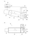
ここで、図2(A)及び図2(B)を参照し、レーザービーム照射ユニット34の構成を説明する。図2(A)は、レーザービーム照射ユニット34の斜視図である。但し、図2(A)では、図1とは異なる向きで見た場合のレーザービーム照射ユニット34が示されている。また、図2(B)は、レーザービーム照射ユニット34の一部断面側面図である。
Here, the configuration of the laser
レーザービーム照射ユニット34は、レーザー媒質を含むレーザー発振器36を有する。レーザー媒質は、例えば、Nd:YVO4結晶、Nd:YAG結晶等のロッドや、希土類元素がドープされたコアを有する光ファイバである。レーザー媒質には、レーザーダイオード等の励起光源(不図示)から励起光が照射される。
The laser
レーザー媒質が励起光を受けてレーザーが発振すると、レーザー発振器36からはレーザービームLが出射する。例えば、Qスイッチパルス発振により、レーザー発振器36からは、所定の繰り返し周波数を有するパルス状であり直線偏光のレーザービームLが出射する。
When the laser medium receives the excitation light and the laser oscillates, the
レーザービームLの出力(即ち、パワー)(単位:W)は、励起光源から照射される励起光のパワーに対応している。例えば、励起光源にレーザーダイオードを使用する場合、レーザーダイオードのN側電極及びP側電極間に供給される電流量を多くするほど、レーザービームLの出力を高くできる。 The output (that is, power) (unit: W) of the laser beam L corresponds to the power of excitation light emitted from the excitation light source. For example, when a laser diode is used as the excitation light source, the output of the laser beam L can be increased by increasing the amount of current supplied between the N-side electrode and the P-side electrode of the laser diode.
レーザービームLの波長は、レーザー加工の態様に応じて適宜設定される。例えば、被加工物11に対して分割起点となる脆弱領域(改質領域)を形成する場合には、被加工物11を透過する波長(例えば、1064nm)を有するレーザービームLが使用される。
The wavelength of the laser beam L is appropriately set depending on the mode of laser processing. For example, when forming a fragile region (modified region) that becomes a starting point of division in the
また、被加工物11に対してアブレーション加工を施す場合には、被加工物11に吸収される波長(例えば、355nm)を有するレーザービームLが使用される。例えば、非線形光学結晶を利用して、1064nmの波長を有するレーザービームL(基本波)を波長変換することで、355nmの波長を有するレーザービームL(第3高調波)を得ることができる。
Further, when performing ablation processing on the
レーザービームLの波長を変換する非線形光学結晶(波長変換部)は、筐体38内に設けられてもよい。レーザー発振器36の下側(図2(A)及び図2(B)に示す右側)には、円筒状の筐体38の上端側が接続されている。
A nonlinear optical crystal (wavelength conversion section) that converts the wavelength of the laser beam L may be provided within the
筐体38の下端部側には、直方体状の接続部材40の一面40a側が固定されている。接続部材40には、レーザービームLを通過させるための開口(不図示)が設けられている。
One
一面40aとは反対側に位置する接続部材40の他面40b側には、集光レンズ42が固定されたレンズマウント44が固定されている。レーザー発振器36から出射されたレーザービームLは、集光レンズ42により、チャックテーブル32で吸引保持された被加工物11に集光される(図1参照)。
A
図2(A)及び図2(B)では、集光レンズ42の光軸42aを一点鎖線で示す。光軸42aは筐体38の中心軸と略一致している。なお、光軸42aは、後述する様に、Z軸方向と平行ではなくZ軸方向に対して傾いている。
In FIGS. 2(A) and 2(B), the
一面40a及び他面40bの間に位置する接続部材40の側面40cには、パワー測定ユニット46が固定されている。パワー測定ユニット46には受光部48が設けられており、側面40cには、受光部48へ光を通過させる開口部が形成されている。
A
受光部48は、レーザー発振器36から集光レンズ42までにおけるレーザービームLの通過経路の延長線上には無く、且つ、光軸42aから離れた位置に配置されている。本実施形態の受光部48は、図2(B)に示す様に、光軸42aに直交する方向において光軸42aから所定距離だけ離れた位置に配置されている。
The
受光部48は、ミラーを僅かに透過するレーザービームL(即ち、透過光)を受光するのではなく、集光レンズ42等の光学部品(即ち、少なくとも集光レンズ42)により反射及び散乱されたレーザービームL(図2(B)において反射散乱光LAと表記する)を受光する。
The
レーザービームLは、集光レンズ42の表面における微細な凹凸や、集光レンズ42の内部の結晶構造に起因して散乱され得るし、集光レンズ42の表面で反射され得る。また、散乱光が、再度、散乱されたり、反射されたりもする。
The laser beam L may be scattered due to minute irregularities on the surface of the condensing
なお、集光レンズ42が複数のレンズの組み合わせで構成されている場合には、1つ目のレンズで散乱された光が2つの目のレンズの表面で散乱されることもあるし、反射されることもある。
Note that when the condensing
ところで、反射散乱光LAのパワー(単位:W)は、ミラーを僅かに透過するレーザービームLのパワーに比べて低い場合がある。しかし、本実施形態では、レーザービーム照射ユニット34に筐体38及び接続部材40を設けることで、パワーが比較的小さい場合でも反射散乱光LAを受光部48で問題なく測定できる。
Incidentally, the power (unit: W) of the reflected and scattered light LA may be lower than the power of the laser beam L that slightly passes through the mirror. However, in this embodiment, by providing the
更に、筐体38及び接続部材40を設けることで、反射散乱光LA以外の光の受光部48への入射光量を低減できるという利点もある。なお、受光部48には、ND(Neutral Density)フィルタ等の光学薄膜を設けてもよい。
Further, by providing the
受光部48は、フォトダイオード等の光電変換素子を含む。受光部48は、受光した光量に応じた電荷を生成し、受光部48に接続された不図示のA/D変換回路(analog-to-digital converter)等により、生成された電荷は電圧値に変換される。そして、この電圧値を示す信号は、後述する制御ユニット50へ出力される。
The
図1に示す様に、制御ユニット50は、プロセッサ(処理装置)50aと、メモリ(記憶装置)50bと、を有するコンピュータによって構成されている。プロセッサ50aは、例えば、CPU(Central Processing Unit)である。
As shown in FIG. 1, the
メモリ50bは、DRAM(Dynamic Random Access Memory)、SRAM(Static Random Access Memory)、ROM(Read Only Memory)等の主記憶装置と、フラッシュメモリ、ハードディスクドライブ、ソリッドステートドライブ等の補助記憶装置と、を含む。
The
補助記憶装置には、所定のプログラムを含むソフトウェアが記憶されている。このソフトウェアに従いプロセッサ50a等を動作させることによって、制御ユニット50の機能が実現される。
The auxiliary storage device stores software including a predetermined program. The functions of the
制御ユニット50は、推定調整部52を有する。推定調整部52は、所定のプログラムをプロセッサ50aで実行することで実現される。推定調整部52は、計算式、テーブル等の所定の関係式に基づいて、反射散乱光LAのパワーをレーザービームLの出力に変換することで、レーザービームLの出力を推定する機能を有する。
The
図3は、レーザービームLの集光点でのパワー(横軸、単位:W)と、反射散乱光LAのパワーに対応する電圧値(縦軸、単位:V)と、を示すグラフである。 FIG. 3 is a graph showing the power at the focal point of the laser beam L (horizontal axis, unit: W) and the voltage value (vertical axis, unit: V) corresponding to the power of the reflected and scattered light LA . be.
図3に示すグラフは、レーザービームLの集光点にパワーメータ等の出力測定器(不図示)を配置して集光点でのパワーを測定すると共に、パワー測定ユニット46で反射散乱光LAを光電変換することで得られる電圧値を測定することで得られた。
The graph shown in FIG. 3 is obtained by arranging an output measuring device (not shown) such as a power meter at the focal point of the laser beam L to measure the power at the focal point, and using a
図3に示す様に、集光点でのレーザービームLの出力(W)と、反射散乱光LAに対応する電圧値(V)と、には、線型の近似式(第1の近似式)が成立する。 As shown in FIG. 3, the output (W) of the laser beam L at the condensing point and the voltage value (V) corresponding to the reflected and scattered light LA are expressed by a linear approximation equation (first approximation equation). ) holds true.
更に、受光部48で受光される反射散乱光LAのパワー(nW)と、パワー測定ユニット46から出される電圧値(V)と、にも、両対数グラフ(不図示)において線型の近似式(第2の近似式)が成立することが知られている。
Furthermore, the power (nW) of the reflected and scattered light LA received by the
推定調整部52は、メモリ50bに予め記憶されたこれら第1及び第2の近似式を利用することで、反射散乱光LAのパワーに基づいて、レーザー発振器36から出射されたレーザービームLの出力(パワー)を推定する。
The
それゆえ、本実施形態では、レーザービームLの光路上にミラーを配置することなく、且つ、レーザー加工を中断することなくレーザービームLの出力を監視できる。また、レーザービームLの光路上にミラーを配置すると、ミラーに付着した汚れ等がレーザー加工性に影響を及ぼす可能性があるが、本実施形態では、ミラーを配置しないので、ミラーによるレーザー加工性の低下を防止できる。 Therefore, in this embodiment, the output of the laser beam L can be monitored without placing a mirror on the optical path of the laser beam L and without interrupting laser processing. Furthermore, if a mirror is placed on the optical path of the laser beam L, dirt etc. adhering to the mirror may affect the laser processability, but in this embodiment, since no mirror is placed, the laser processability using the mirror is can prevent a decline in
再び図1を参照すると、アーム部8aの先端部には、レーザービーム照射ユニット34に隣接して顕微鏡カメラユニット54が設けられている。チャックテーブル32で吸引保持された被加工物11を顕微鏡カメラユニット54で撮像することで得られた画像は、タッチパネル56に表示される。
Referring again to FIG. 1, a
タッチパネル56は、レーザー加工装置2の外表面を構成する不図示の外装材(即ち、パネル)のうち前方側の側面に設けられている。タッチパネル56は、顕微鏡カメラユニット54で得られた画像や、予め定められた画面、文字、数字等を表示する表示装置として機能する。加えて、タッチパネル56は、作業者の指示を制御ユニット50へ入力するための入力装置としても機能する。
The
レーザー加工装置2の外装材の上面には、円柱状の表示灯58が設けられている。表示灯58は、赤色、黄色、青色等の予め定められた色で点灯するLED(Light Emitting Diode)ランプを有する。LEDランプを点灯させることで、レーザー加工装置2の稼働状態を作業者へ知らせることができる。
A
表示灯58には、スピーカ(不図示)も併設されている。スピーカは、例えば、レーザー加工装置2に異常が発生した場合や、予め設定された加工が終了した場合に、所定の音を発することで、異常が発生した旨や、加工が終了した旨を作業者に知らせる。なお、スピーカは、レーザー加工装置2において表示灯58とは別途に設けられてもよい。
The
タッチパネル56、表示灯58及びスピーカの少なくとも一つは、制御ユニット50によって動作が制御される警報ユニットとして機能する。推定調整部52により推定されたレーザービームLの出力が所定の範囲を超える場合に、制御ユニット50は、警報ユニットに警報を出させる。
At least one of the
例えば、タッチパネル56は、異常が発生した旨の警報を所定の文字、色等を用いて画面に表示する。また、表示灯58は、赤色のLEDランプを点灯させると共に、スピーカにより異常が発生した旨の所定の警報音を鳴らす。
For example, the
推定されたレーザービームLの出力が所定の範囲を超えた場合、レーザービームLの出力が所定範囲となる様に、例えば、推定調整部52がレーザービームLの出力を調整する。つまり、推定調整部52がレーザービーム出力調整ユニットとして機能する。
If the estimated output of the laser beam L exceeds a predetermined range, the
推定調整部52は、例えば、レーザー発振器36を構成するレーザーダイオードへ印加される電圧値を変更して、レーザーダイオードに注入される電流量を調整することにより、レーザービームLの出力を調整する。
The
ところで、被加工物11に対してレーザー加工を施す際には、まず、図4に示す様に、被加工物11の裏面11b側を保持面32aで吸引保持する。なお、被加工物11の表面11a側には、複数のストリート(分割予定ライン)13が格子状に設定されている。
By the way, when performing laser processing on the
複数のストリート13で区画された矩形状の領域の各々には、デバイス15が形成されている。デバイス15は、IC(Integrated Circuit)、LED、MEMS(Micro Electro Mechanical Systems)等である。
A
顕微鏡カメラユニット54を利用してアライメントを行い、ストリート13がX軸方向と略平行になるようにチャックテーブル32の向きを調整した後、レーザービームLの集光点を表面11a近傍の所定の高さ位置に位置付けた状態で、チャックテーブル32をX軸方向に沿って加工送りする。
After performing alignment using the
この様に、被加工物11に対してレーザービームLを照射することで、被加工物11に対してレーザー加工が施される。レーザービームLは、直線偏光を有するパルス状のレーザービームであり、被加工物11を透過する又は被加工物11に吸収される所定の波長を有する。
By irradiating the
集光レンズ42は、図4に示す様に、光軸42aが保持面32aに対して直交せずに所定角度αだけ傾く様に配置されている。図4は、集光レンズ42の光軸42aの傾きを示す一部断面側面図である。
As shown in FIG. 4, the condensing
図4のYZ平面視において、保持面32aの法線32bに対する光軸42aの角度(所定角度α)は、例えば30度である。しかし、30度は一例に過ぎず、所定角度αは30度に限定されない。
In the YZ plane view of FIG. 4, the angle (predetermined angle α) of the
仮に、光軸42aを法線32bと平行にする場合、被加工物11から反射及び散乱されたレーザービームLが、レーザービーム照射ユニット34に戻りやすくなるので、光軸42aを傾ける場合に比べて、パワー測定ユニット46の受光部48で測定されるノイズが大きくなる。
If the
本実施形態では、光軸42aを法線32bに対して所定角度αだけ傾けることで、光軸42aを法線32bと平行にする場合に比べて被加工物11での反射及び散乱に起因するノイズを低減できるので、反射散乱光LAの測定精度を高くできる。
In the present embodiment, by tilting the
(第2の実施形態)次に、図5を参照して、第2の実施形態について説明する。図5は、第2の実施形態に係るレーザービーム照射ユニット34の一部断面側面図である。本実施形態のレーザービーム照射ユニット34は、筐体38を有さない。それゆえ、レーザー発振器36、レンズマウント44及びパワー測定ユニット46の各々は、筐体38ではなく、アーム部8aに固定されている。
(Second Embodiment) Next, a second embodiment will be described with reference to FIG. FIG. 5 is a partially sectional side view of the laser
図5に示す様に、パワー測定ユニット46は、集光レンズ42のレーザー発振器36側の表面を受光部48が向く様に、光軸42aに対して傾けられている。これにより、第1の実施形態に比べて、反射散乱光LAが受光部48に入りやすくなる。
As shown in FIG. 5, the
それゆえ、第2の実施形態では、第1の実施形態に比べて受光部48へ入射する反射散乱光LAの光量が多くなり、測定感度が向上するという利点がある。なお、反射散乱光LA以外の光を遮断するために、受光部48には、バンドパスフィルタやNDフィルタ等の光学薄膜を設けてもよい。
Therefore, the second embodiment has the advantage that the amount of reflected and scattered light LA that enters the
(第3の実施形態)次に、図6を参照して、第3の実施形態について説明する。図6は、第3の実施形態に係るレーザービーム照射ユニット34の一部断面側面図である。本実施形態のレーザービーム照射ユニット34も、筐体38を有さない。レーザー発振器36、レンズマウント44及びパワー測定ユニット46の各々は、筐体38ではなく、アーム部8aに固定されている。
(Third Embodiment) Next, a third embodiment will be described with reference to FIG. FIG. 6 is a partially sectional side view of the laser
図6に示す様に、パワー測定ユニット46は、集光レンズ42のレーザー発振器36と反対側(即ち、チャックテーブル32側)の表面を受光部48が向く様に、光軸42aに対して傾けられている。これにより、第1の実施形態に比べて、反射散乱光LAが受光部48に入りやすくなる。
As shown in FIG. 6, the
それゆえ、第3の実施形態でも、第1の実施形態に比べて受光部48へ入射する反射散乱光LAの光量が多くなり、測定感度が向上するという利点がある。なお、反射散乱光LA以外の光を遮断するために、受光部48には、バンドパスフィルタやNDフィルタ等の光学薄膜を設けてもよい。
Therefore, the third embodiment also has the advantage that the amount of reflected and scattered light LA that enters the
(変形例)次に、図7(A)から図7(C)を参照し、第1から第3の変形例について説明する。なお、第1から第3の変形例に係るレーザービーム照射ユニット34は、筐体38を有するが、第2及び第3の実施形態の様に、筐体38を有しない構成としてもよい。
(Modifications) Next, first to third modifications will be described with reference to FIGS. 7(A) to 7(C). Note that, although the laser
図7(A)は、レーザービーム出力調整ユニットの第1の変形例を示す図である。図7(A)に示す第1の変形例では、光軸42a上に配置された半波長板60と、偏光子62と、をレーザービーム出力調整ユニットとして用いる。
FIG. 7(A) is a diagram showing a first modification of the laser beam output adjustment unit. In a first modification shown in FIG. 7A, a half-
半波長板60の光学軸は、光軸42aに対して直交する様に配置されている。半波長板60は、その光学軸が光軸42aの周りで回転可能な様に、モータを有する回転マウント60aに取り付けられている。なお、図7(A)では、便宜上、回転マウント60aを簡略化して示す。
The optical axis of the half-
回転マウント60aによる半波長板60の光学軸の回転角度は、上述の制御ユニット50により精密に制御される。半波長板60は、直線偏光の振動方向(例えば、電場の振動方向)を、光軸42aの周りに回転させる機能を有する。これに対して、偏光子62は、予め定められた特定の振動方向を有する直線偏光だけを透過させる様に、光軸42a上に配置されている。
The rotation angle of the optical axis of the half-
回転マウント60aにより半波長板60を透過する直線偏光の振動方向を調整することにより、レーザービームLが偏光子62を全く透過しない状態(0%、即ち、クロスニコル)と、偏光子62を完全に透過する状態(100%)と、の間で、レーザービーム照射ユニット34から被加工物11へ照射されるレーザービームLの出力を無段階に調整できる。
By adjusting the vibration direction of the linearly polarized light that passes through the half-
なお、第1の変形例では、集光レンズ42からの反射散乱光LAに加えて、半波長板60で反射及び散乱されるレーザービームLの反射散乱光LAを、パワー測定ユニット46の受光部48で受光することもできる。
In the first modification, in addition to the reflected and scattered light LA from the
図7(B)は、レーザービーム出力調整ユニットの第2の変形例を示す図である。第2の変形例では、半波長板60に代えて、電気光学変調器(EOM:electro-optic modulator)64が光軸42a上に設けられている。
FIG. 7(B) is a diagram showing a second modified example of the laser beam output adjustment unit. In the second modification, instead of the half-
電気光学変調器64は、電気光学変調器64に印加される電圧値に応じて直線偏光の振動方向を光軸42aの周りに回転させる機能を有する。つまり、第2の変形例では、電気光学変調器64と、偏光子62と、をレーザービーム出力調整ユニットとして用いる。第2の変形例でも、被加工物11へ照射されるレーザービームLの出力を無段階に調整できる。
The electro-
図7(C)は、レーザービーム出力調整ユニットの第3の変形例を示す図である。第3の変形例では、音響光学変調器(AOM:acousto-optic modulator)66が光軸42a上に設けられている。第3の変形例では、音響光学変調器66をレーザービーム出力調整ユニットとして用いる。
FIG. 7(C) is a diagram showing a third modification of the laser beam output adjustment unit. In a third modification, an acousto-optic modulator (AOM) 66 is provided on the
音響光学変調器66に所定の電圧が印加されると、音響光学効果によりレーザービームLは回折される。このとき、レーザービームLは、例えば、1次回折光が最も高いパワーを有する様に回折される。
When a predetermined voltage is applied to the acousto-
1次回折光が集光レンズ42へ向けて照射されない様に光学系を設定することで、音響光学変調器66は、レーザービームLを出力させるオン状態と、レーザービームLを出力させないオフ状態と、を切り替えるスイッチ素子として機能する。
By setting the optical system so that the first-order diffracted light is not irradiated toward the condensing
例えば、推定調整部52により推定されたレーザービームLの出力が所定の範囲を超える場合に、制御ユニット50は、音響光学変調器66に所定の電圧を印加し、レーザービームLをオフ状態とする。これにより、被加工物11の異常なレーザー加工が施されることを防止できる。
For example, when the output of the laser beam L estimated by the
その他、上述の実施形態に係る構造、方法等は、本発明の目的の範囲を逸脱しない限りにおいて適宜変更して実施できる。第2又は第3の実施形態に、第1から第3の変形例を適用してもよい。 In addition, the structure, method, etc. according to the above-described embodiments can be modified and implemented as appropriate without departing from the scope of the objective of the present invention. The first to third modifications may be applied to the second or third embodiment.
また、上述の説明では、レーザービーム照射ユニット34が上側に位置し、チャックテーブル32が下側に位置する例を述べたが、チャックテーブル32が上側に位置し、レーザービーム照射ユニット34が下側に位置してもよい。
Furthermore, in the above description, an example was described in which the laser
上側に配置されたチャックテーブル32で被加工物11を吸引保持した状態で、下側に配置されたレーザービーム照射ユニット34から当該被加工物11へレーザービームLを照射するレーザー加工装置にも、上述の実施形態、変形例等を適用できる。
The laser processing device also includes a laser processing device that irradiates the
2:レーザー加工装置、4:基台、6:平板部、8:壁部、8a:アーム部
10:Y軸方向移動ユニット、12:Y軸ガイドレール、14:移動テーブル
11:被加工物、11a:表面、11b:裏面、13:ストリート、15:デバイス
16:ねじ軸、18:駆動源
20:X軸方向移動ユニット、22:X軸ガイドレール、24:移動テーブル
26:ねじ軸、28:駆動源
30:回転駆動機構、32:チャックテーブル、32a:保持面、32b:法線
34:レーザービーム照射ユニット、36:レーザー発振器
38:筐体、40:接続部材、40a:一面、40b:他面、40c:側面
42:集光レンズ、42a:光軸、44:レンズマウント
46:パワー測定ユニット、48:受光部
50:制御ユニット、50a:プロセッサ、50b:メモリ、52:推定調整部
54:顕微鏡カメラユニット、56:タッチパネル、58:表示灯
60:半波長板、60a:回転マウント、62:偏光子
64:電気光学変調器、66:音響光学変調器
L:レーザービーム、LA:反射散乱光、α:所定角度
2: laser processing device, 4: base, 6: flat plate section, 8: wall section, 8a: arm section 10: Y-axis direction movement unit, 12: Y-axis guide rail, 14: moving table 11: workpiece, 11a: Front surface, 11b: Back surface, 13: Street, 15: Device 16: Screw shaft, 18: Drive source 20: X-axis direction movement unit, 22: X-axis guide rail, 24: Moving table 26: Screw shaft, 28: Drive source 30: Rotary drive mechanism, 32: Chuck table, 32a: Holding surface, 32b: Normal line 34: Laser beam irradiation unit, 36: Laser oscillator 38: Housing, 40: Connection member, 40a: One surface, 40b: Others surface, 40c: side surface 42: condensing lens, 42a: optical axis, 44: lens mount 46: power measurement unit, 48: light receiving section 50: control unit, 50a: processor, 50b: memory, 52: estimation adjustment section 54: Microscope camera unit, 56: touch panel, 58: indicator light 60: half-wave plate, 60a: rotation mount, 62: polarizer 64: electro-optic modulator, 66: acousto-optic modulator L: laser beam, L A : reflective scattering Light, α: Predetermined angle
Claims (4)
被加工物を吸引保持する吸引保持板と、
該吸引保持板で吸引保持された該被加工物に対してレーザービームを照射するレーザービーム照射ユニットと、
該レーザービームの出力が所定の範囲を超えた場合に警報を発する警報ユニットと、
メモリ及びプロセッサを備え、該警報ユニットの動作を制御する制御ユニットと、
を備え、
該レーザービーム照射ユニットは、
レーザー発振器と、
該レーザー発振器から出射された該レーザービームを集光させる集光レンズと、
少なくとも該集光レンズで反射及び散乱された該レーザービームのパワーを測定するパワー測定ユニットと、
を有し、
該制御ユニットは、
該パワー測定ユニットで測定されたパワーに基づいて該レーザー発振器から出射された該レーザービームの出力を推定し、
推定された該レーザービームの出力が所定の範囲を超える場合、該警報ユニットに警報を出させることを特徴とするレーザー加工装置。 A laser processing device,
a suction holding plate that suctions and holds the workpiece;
a laser beam irradiation unit that irradiates the workpiece held by the suction holding plate with a laser beam;
an alarm unit that issues an alarm when the output of the laser beam exceeds a predetermined range;
a control unit comprising a memory and a processor and controlling the operation of the alarm unit;
Equipped with
The laser beam irradiation unit is
a laser oscillator,
a condensing lens that condenses the laser beam emitted from the laser oscillator;
a power measurement unit that measures the power of the laser beam reflected and scattered by at least the condenser lens;
has
The control unit includes:
estimating the output of the laser beam emitted from the laser oscillator based on the power measured by the power measurement unit;
A laser processing device characterized by causing the alarm unit to issue an alarm when the estimated output of the laser beam exceeds a predetermined range.
Priority Applications (1)
| Application Number | Priority Date | Filing Date | Title |
|---|---|---|---|
| JP2022115586A JP2024013473A (en) | 2022-07-20 | 2022-07-20 | laser processing equipment |
Applications Claiming Priority (1)
| Application Number | Priority Date | Filing Date | Title |
|---|---|---|---|
| JP2022115586A JP2024013473A (en) | 2022-07-20 | 2022-07-20 | laser processing equipment |
Publications (1)
| Publication Number | Publication Date |
|---|---|
| JP2024013473A true JP2024013473A (en) | 2024-02-01 |
Family
ID=89718200
Family Applications (1)
| Application Number | Title | Priority Date | Filing Date |
|---|---|---|---|
| JP2022115586A Pending JP2024013473A (en) | 2022-07-20 | 2022-07-20 | laser processing equipment |
Country Status (1)
| Country | Link |
|---|---|
| JP (1) | JP2024013473A (en) |
Citations (4)
| Publication number | Priority date | Publication date | Assignee | Title |
|---|---|---|---|---|
| JPS6066737A (en) * | 1983-09-20 | 1985-04-16 | 三菱電機株式会社 | Laser irradiating apparatus |
| JPH03184684A (en) * | 1989-12-13 | 1991-08-12 | Yamazaki Mazak Corp | Processing control method for laser beam machine |
| JPH1197776A (en) * | 1997-09-18 | 1999-04-09 | Amada Eng Center Co Ltd | Laser detector and detecting method for laser beam machine, and method and system for outputting laser using them |
| JP2021030283A (en) * | 2019-08-27 | 2021-03-01 | 株式会社ディスコ | Laser processing device |
-
2022
- 2022-07-20 JP JP2022115586A patent/JP2024013473A/en active Pending
Patent Citations (4)
| Publication number | Priority date | Publication date | Assignee | Title |
|---|---|---|---|---|
| JPS6066737A (en) * | 1983-09-20 | 1985-04-16 | 三菱電機株式会社 | Laser irradiating apparatus |
| JPH03184684A (en) * | 1989-12-13 | 1991-08-12 | Yamazaki Mazak Corp | Processing control method for laser beam machine |
| JPH1197776A (en) * | 1997-09-18 | 1999-04-09 | Amada Eng Center Co Ltd | Laser detector and detecting method for laser beam machine, and method and system for outputting laser using them |
| JP2021030283A (en) * | 2019-08-27 | 2021-03-01 | 株式会社ディスコ | Laser processing device |
Similar Documents
| Publication | Publication Date | Title |
|---|---|---|
| KR102736968B1 (en) | Laser processing device | |
| US9791411B2 (en) | Processing apparatus including a three-dimensional interferometric imager | |
| KR101666462B1 (en) | Autofocus method and apparatus for wafer scribing | |
| US5670068A (en) | Apparatus for laser processing and monitoring | |
| US20130027690A1 (en) | Laser beam spot shape detecting method | |
| US9743503B2 (en) | Laser device and extreme ultraviolet light generation system | |
| JP6644563B2 (en) | Laser light irradiation device | |
| CN115112578B (en) | Imaging spectrum system based on pump detection, detection imaging method and application | |
| CN110116117A (en) | A kind of laser composite cleaning system and method | |
| JP6995465B2 (en) | Laser oscillator and laser processing equipment | |
| US20210170524A1 (en) | Laser beam adjustment system and laser processing apparatus | |
| JP2016010809A (en) | Laser processing equipment | |
| KR20150057997A (en) | Detecting apparatus | |
| KR102697771B1 (en) | Laser processing method and laser processing device | |
| JP2024013473A (en) | laser processing equipment | |
| US20120032687A1 (en) | Detection apparatus for detecting electric field distribution or carrier distribution based on the intensity of high-order harmonics | |
| CN116209537A (en) | Apparatus and method for semiconductor package failure analysis | |
| TW202410233A (en) | Laser processing device | |
| JP2022000909A (en) | Laser oscillator and laser processing device | |
| JP7356235B2 (en) | laser processing equipment | |
| KR20180098810A (en) | Annealing apparatus and annealing method | |
| US12397370B2 (en) | Pulse duration measuring apparatus | |
| TWI889949B (en) | Laser processing equipment | |
| TWI816446B (en) | Laser application processing system and method thereof | |
| JP2006128557A (en) | Laser crystal evaluation system |
Legal Events
| Date | Code | Title | Description |
|---|---|---|---|
| A621 | Written request for application examination |
Free format text: JAPANESE INTERMEDIATE CODE: A621 Effective date: 20250522 |
|
| A977 | Report on retrieval |
Free format text: JAPANESE INTERMEDIATE CODE: A971007 Effective date: 20260205 |
|
| A131 | Notification of reasons for refusal |
Free format text: JAPANESE INTERMEDIATE CODE: A131 Effective date: 20260224 |
|
| A521 | Request for written amendment filed |
Free format text: JAPANESE INTERMEDIATE CODE: A523 Effective date: 20260331 |