JP2024106830A - Self-location acquisition device - Google Patents
Self-location acquisition device Download PDFInfo
- Publication number
- JP2024106830A JP2024106830A JP2023011293A JP2023011293A JP2024106830A JP 2024106830 A JP2024106830 A JP 2024106830A JP 2023011293 A JP2023011293 A JP 2023011293A JP 2023011293 A JP2023011293 A JP 2023011293A JP 2024106830 A JP2024106830 A JP 2024106830A
- Authority
- JP
- Japan
- Prior art keywords
- positioning
- information
- self
- vehicle
- time
- Prior art date
- Legal status (The legal status is an assumption and is not a legal conclusion. Google has not performed a legal analysis and makes no representation as to the accuracy of the status listed.)
- Granted
Links
Images






Classifications
-
- G—PHYSICS
- G01—MEASURING; TESTING
- G01S—RADIO DIRECTION-FINDING; RADIO NAVIGATION; DETERMINING DISTANCE OR VELOCITY BY USE OF RADIO WAVES; LOCATING OR PRESENCE-DETECTING BY USE OF THE REFLECTION OR RERADIATION OF RADIO WAVES; ANALOGOUS ARRANGEMENTS USING OTHER WAVES
- G01S19/00—Satellite radio beacon positioning systems; Determining position, velocity or attitude using signals transmitted by such systems
- G01S19/38—Determining a navigation solution using signals transmitted by a satellite radio beacon positioning system
- G01S19/39—Determining a navigation solution using signals transmitted by a satellite radio beacon positioning system the satellite radio beacon positioning system transmitting time-stamped messages, e.g. GPS [Global Positioning System], GLONASS [Global Orbiting Navigation Satellite System] or GALILEO
- G01S19/42—Determining position
- G01S19/421—Determining position by combining or switching between position solutions or signals derived from different satellite radio beacon positioning systems; by combining or switching between position solutions or signals derived from different modes of operation in a single system
- G01S19/426—Determining position by combining or switching between position solutions or signals derived from different satellite radio beacon positioning systems; by combining or switching between position solutions or signals derived from different modes of operation in a single system by combining or switching between position solutions or signals derived from different modes of operation in a single system
-
- G—PHYSICS
- G01—MEASURING; TESTING
- G01S—RADIO DIRECTION-FINDING; RADIO NAVIGATION; DETERMINING DISTANCE OR VELOCITY BY USE OF RADIO WAVES; LOCATING OR PRESENCE-DETECTING BY USE OF THE REFLECTION OR RERADIATION OF RADIO WAVES; ANALOGOUS ARRANGEMENTS USING OTHER WAVES
- G01S5/00—Position-fixing by co-ordinating two or more direction or position line determinations; Position-fixing by co-ordinating two or more distance determinations
- G01S5/01—Determining conditions which influence positioning, e.g. radio environment, state of motion or energy consumption
- G01S5/012—Identifying whether indoors or outdoors
-
- G—PHYSICS
- G01—MEASURING; TESTING
- G01S—RADIO DIRECTION-FINDING; RADIO NAVIGATION; DETERMINING DISTANCE OR VELOCITY BY USE OF RADIO WAVES; LOCATING OR PRESENCE-DETECTING BY USE OF THE REFLECTION OR RERADIATION OF RADIO WAVES; ANALOGOUS ARRANGEMENTS USING OTHER WAVES
- G01S5/00—Position-fixing by co-ordinating two or more direction or position line determinations; Position-fixing by co-ordinating two or more distance determinations
- G01S5/01—Determining conditions which influence positioning, e.g. radio environment, state of motion or energy consumption
- G01S5/017—Detecting state or type of motion
-
- G—PHYSICS
- G01—MEASURING; TESTING
- G01S—RADIO DIRECTION-FINDING; RADIO NAVIGATION; DETERMINING DISTANCE OR VELOCITY BY USE OF RADIO WAVES; LOCATING OR PRESENCE-DETECTING BY USE OF THE REFLECTION OR RERADIATION OF RADIO WAVES; ANALOGOUS ARRANGEMENTS USING OTHER WAVES
- G01S5/00—Position-fixing by co-ordinating two or more direction or position line determinations; Position-fixing by co-ordinating two or more distance determinations
- G01S5/01—Determining conditions which influence positioning, e.g. radio environment, state of motion or energy consumption
- G01S5/018—Involving non-radio wave signals or measurements
-
- G—PHYSICS
- G01—MEASURING; TESTING
- G01S—RADIO DIRECTION-FINDING; RADIO NAVIGATION; DETERMINING DISTANCE OR VELOCITY BY USE OF RADIO WAVES; LOCATING OR PRESENCE-DETECTING BY USE OF THE REFLECTION OR RERADIATION OF RADIO WAVES; ANALOGOUS ARRANGEMENTS USING OTHER WAVES
- G01S19/00—Satellite radio beacon positioning systems; Determining position, velocity or attitude using signals transmitted by such systems
- G01S19/01—Satellite radio beacon positioning systems transmitting time-stamped messages, e.g. GPS [Global Positioning System], GLONASS [Global Orbiting Navigation Satellite System] or GALILEO
- G01S19/13—Receivers
- G01S19/14—Receivers specially adapted for specific applications
Landscapes
- Engineering & Computer Science (AREA)
- Radar, Positioning & Navigation (AREA)
- Remote Sensing (AREA)
- Physics & Mathematics (AREA)
- General Physics & Mathematics (AREA)
- Computer Networks & Wireless Communication (AREA)
- Position Fixing By Use Of Radio Waves (AREA)
Abstract
Description
本発明は、自己位置取得装置に関する。 The present invention relates to a self-location acquisition device.
従来から移動体に関して現在の自己位置を計測する技術が知られている。例えば、測位衛星から受信した電波に載っている受信情報に基づいて自車両の測位を車両単独で行う単独測位の方式が知られている。また、受信情報及びネットワークを介して測位サーバから受信した測位補助情報に基づいて自車両の測位を行うネットワークアシスト方式も知られている。そして、特許文献1には、上述の2つの測位方式を組み合わせて使用する技術が開示されている。
Technologies for measuring the current position of a moving object have been known for some time. For example, a standalone positioning method is known in which the vehicle determines its own position based on received information carried in radio waves received from a positioning satellite. Also known is a network-assisted method in which the vehicle determines its own position based on received information and auxiliary positioning information received from a positioning server via a network.
特許文献1の技術では、上方が閉じられた空間内に車両が位置することを検出し、または、近い将来に移動することを予測し、もしくは、電波の品質が所定レベルよりも低下した場合に、単独測位の方式からネットワークアシスト方式に測位方式を切り替えている。
The technology in
しかしながら、上方が閉じられた空間であっても、歩道橋などのように、測位衛星と自車両の間が瞬間的に遮られる場合も多々考えられる。そのような場合であっても、特許文献1に記載の技術のように都度ネットワークアシスト方式に切り替えるとネットワーク利用料などの別途コストが過度に発生してしまうおそれがある。
However, even in a space that is closed above, there are many cases where the path between the positioning satellite and the vehicle may be momentarily blocked, such as on a pedestrian bridge. Even in such cases, if the system switches to the network-assisted method each time, as in the technology described in
本発明は、上記に鑑みてなされたものであり、ネットワークアシスト方式の利用を最小限とし、可能な限り単独測位の方式によって測位することで、コストを抑えながら安定して高精度測位を行うことが可能な自己位置取得装置を提供することを目的とする。 The present invention has been made in consideration of the above, and aims to provide a self-location acquisition device that can perform stable, high-precision positioning while keeping costs down by minimizing the use of network-assisted methods and performing positioning using standalone positioning methods as much as possible.
上記課題を解決するために、本発明の自己位置取得装置は、測位衛星から受信した測位電波の受信情報及び該受信情報を補強する補強情報に基づいて測位を行う第1測位方式と、該受信情報及びネットワークを介して測位サーバから受信した測位補助情報に基づいて測位を行う第2測位方式を、切り替える自車両に搭載された自己位置取得装置であって、前記第1測位方式において精度が低下する阻害期間、及び、前記補強情報の有効期間に基づいて、該第1測位方式を前記第2測位方式に切り替えることを特徴とする。 In order to solve the above problem, the self-location acquisition device of the present invention is a self-location acquisition device mounted on a vehicle that switches between a first positioning method that performs positioning based on reception information of positioning radio waves received from a positioning satellite and reinforcement information that reinforces the reception information, and a second positioning method that performs positioning based on the reception information and auxiliary positioning information received from a positioning server via a network, and is characterized in that the first positioning method is switched to the second positioning method based on an inhibition period during which accuracy decreases in the first positioning method and the validity period of the reinforcement information.
本発明によれば、ネットワークアシスト方式の利用を最小限とし、可能な限り単独測位の方式によって測位することで、コストを抑えながら安定して高精度測位を行うことが可能な自己位置取得装置を提供することができる。
上記以外の課題、構成及び効果は、以下の実施形態の説明により明らかにされる。
According to the present invention, by minimizing the use of network-assisted methods and performing positioning using a standalone positioning method as much as possible, it is possible to provide a self-location acquisition device that can perform stable, high-precision positioning while keeping costs down.
Problems, configurations and effects other than those described above will become apparent from the following description of the embodiments.
以下、本発明の実施形態について図面を用いて説明する。なお、各実施形態において同一の符号を付された構成については、特に言及しない限り、各実施形態において同様の機能を有し、その説明を省略する。 Embodiments of the present invention will be described below with reference to the drawings. Note that components with the same reference numerals in each embodiment have the same functions in each embodiment unless otherwise specified, and the description thereof will be omitted.
[第1実施形態]
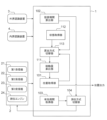
図1は、第1実施形態に係る自己位置取得装置1の構成を説明するブロック図である。自己位置取得装置1は、自車両に搭載されており、直線路やカーブといった走行経路に対する自車両の位置を自己位置として取得し、車両内の別装置に送信する。
[First embodiment]
1 is a block diagram illustrating the configuration of a self-
自己位置取得装置1には、測位装置2と外界認識装置3が接続されている。
The self-
測位装置2は、自車両に搭載されており、複数の測位衛星から測位電波を受信する第1受信機21と、これら複数の測位衛星とは異なる他の測位衛星から測位電波の受信情報を補強する補強情報を受信する第2受信機22と、ネットワークを介して測位サーバから測位電波の受信情報を補助する測位補助情報を受信する第3受信機23と、測位電波の受信情報と補強情報に基づく第1測位方式、または、測位電波の受信情報と測位補助情報に基づく第2測位方式のいずれかにより測位演算を行う測位エンジン24と、を有する。測位電波の受信情報には、測位衛星が測位電波を送信した日付及び時刻、測位衛星自身の位置情報、他の測位衛星の軌道情報、及び、電離層の情報の少なくとも一つが含まれている。
The
第1受信機21と第2受信機22は、GPS衛星や準天頂衛星などの測位衛星から測位電波や補強情報を受信するGNSS受信機であり、第3受信機23は、例えば一般にネットワーク型RTK-GNSSと呼ばれる測位方式に用いる測位補助情報を受信するための通信装置である。測位エンジン24は、例えばマイクロコントローラによって構成されており、測位演算により緯度、経度、高度及び時刻などの自己位置情報を算出して自己位置取得装置1に出力する処理を行う。測位装置2は、第2受信機22により取得した補強情報についても自己位置取得装置1に出力する。
The
第1受信機21と第2受信機22は、GNSS受信機に限らず、測位電波の受信情報に基づいて測位衛星の信号を追跡する単純な機器であってもよく、この場合は、自己位置取得装置1において自己位置情報の算出が行われる。第1受信機21と第2受信機22は別体のものに限定されず、同一の機体内において一体に構成され、測位電波と補強情報の両方の受信を行う構成のものであってもよい。
The
第1測位方式は、測位衛星の測位電波に基づいて単独で現在位置を算出する単独測位の方式である。第1測位方式は、本実施形態に係る自己位置取得装置1においては、測位電波の受信が遮られて測位が困難にならない限り、優先的に用いられる測位方式である。第1測位方式では、例えば、CLAS(Centimeter Level Augmentation Service)や、HAS(High Accuracy Service)などの測位補強情報サービスにより、特定の測位衛星から送信される補強情報を利用することで、高精度測位を行う。
The first positioning method is a standalone positioning method that calculates the current position independently based on the positioning radio waves of a positioning satellite. In the self-
第1測位方式では、補強情報に含まれる衛星時計誤差、衛星軌道誤差、衛星信号バイアス、電離圏遅延誤差といった要因ごとの誤差量が取得される。そして、要因ごとの誤差量を用いて、他の複数の測位衛星から受信した測位電波の受信情報を補正することで高精度測位を行う。 In the first positioning method, the amount of error for each factor, such as satellite clock error, satellite orbit error, satellite signal bias, and ionospheric delay error, contained in the augmentation information is obtained. Then, the amount of error for each factor is used to correct the reception information of the positioning radio waves received from multiple other positioning satellites, thereby performing high-precision positioning.
第1測位方式では、1フレーム分の補強情報を連続して受信する必要がある。例えば、CLASでは準天頂衛星みちびきから送信される1フレーム分の補強情報の受信に必要な時間は30秒である。例えば、1フレーム分の補強情報の受信途中で、補強情報を送信する特定の測位衛星と測位装置2の受信アンテナとの間に、歩道橋や跨道橋、トンネルといった障害物が介在されて、第2受信機22による補強情報の受信が妨げられると、当該補強情報は使用できなくなり、フレームに含まれる要因ごとの誤差量を用いた補正ができなくなる。
In the first positioning method, it is necessary to continuously receive one frame of reinforcement information. For example, in CLAS, it takes 30 seconds to receive one frame of reinforcement information transmitted from the Quasi-Zenith Satellite Michibiki. For example, if an obstacle such as a footbridge, overpass, or tunnel is placed between a specific positioning satellite transmitting the reinforcement information and the receiving antenna of the
また、補強情報は、1フレーム分の受信が妨げられることなく完了した場合であっても、時間経過に伴って要因ごとの誤差量が変化していくという特徴を有している。したがって、受信完了から一定時間が経過すると当該補強情報は使用できなくなり、補強情報のフレームに含まれる要因ごとの誤差量を用いた補正ができなくなる。補強情報の受信を完了してからその補強情報の使用ができなくなるまでの時間は、測位補強情報サービスの種類や期待する測位精度によって異なるが、60秒程度に設定されることが多い。 Furthermore, a feature of augmentation information is that even if reception of one frame is completed without interruption, the amount of error for each cause changes over time. Therefore, once a certain amount of time has passed since reception is complete, the augmentation information becomes unusable, and correction using the amount of error for each cause contained in the augmentation information frame becomes impossible. The time from completion of reception of the augmentation information until it becomes unusable varies depending on the type of positioning augmentation information service and the expected positioning accuracy, but is often set to around 60 seconds.
第2測位方式は、通信ネットワークを介して測位サーバから受信した測位補助情報と、測位衛星からの測位電波の受信情報とに基づいて現在位置を算出するネットワークアシスト方式である。第2測位方式として、例えば測位衛星からの測位電波に加え、自車両の近傍に設置または設定された基準局での測位電波の観測情報に基づいて測位を行うRTK(Real Time Kinematic)方式を用いることができる。RTK方式は、二重位相差に基づいて測位誤差を除去する方式であり、前述の測位補強情報サービスのような補強情報を受信し続ける必要はない。第2測位方式では、常時基準局の観測情報を通信回線経由で取得し続ける必要がある。したがって、測位サーバとの間の通信に有料のネットワークを使用する場合には、通信の通信料が発生する。 The second positioning method is a network-assisted method that calculates the current position based on auxiliary positioning information received from a positioning server via a communication network and information on received positioning radio waves from a positioning satellite. As the second positioning method, for example, the RTK (Real Time Kinematic) method can be used, which performs positioning based on observation information of positioning radio waves at a reference station installed or set near the vehicle, in addition to positioning radio waves from a positioning satellite. The RTK method is a method that removes positioning errors based on double phase differences, and does not require continuous reception of augmentation information such as the aforementioned positioning augmentation information service. In the second positioning method, it is necessary to constantly obtain observation information from the reference station via a communication line. Therefore, if a paid network is used for communication with the positioning server, communication charges will be incurred.
外界認識装置3は、自車両に搭載されており、自車両の周囲の外界を認識する。外界認識装置3としては、主にステレオカメラやLiDARといった対象物との距離や位置関係を測るセンサ類を意図している。その他、外界認識装置3としては、対象物の大きさや、種別を観測することができるものであることが好ましい。外界認識装置3は、特定の測位衛星から補強情報が受信できずに測位精度が低下する空間などの対象物の情報(以下、対象物情報ともいう)を取得する。対象物情報は、対象物までの距離の情報を含み、好ましくは対象物までの距離、自車両が対象物に到達するまでの到達時間、自車両と対象物との位置関係、対象物の大きさ、及び対象物の種別の情報を含む。外界認識装置3は、計測によって得た対象物情報を、自己位置取得装置1に送信する。
The external
本実施形態においては、対象物のうち、自車進行路にかかる歩道橋及び高架橋、並びに、自車進行路沿いに存在する建築物などの、補強情報を送信する特定の測位衛星と各受信機の受信アンテナとの間を遮る障害物、すなわち自車両の上空を遮蔽する可能性のある外的な環境上の障害物を阻害要因とみなす。そして、阻害要因までの距離、到達時間、阻害要因の大きさ、自車両と阻害要因との位置関係、及び阻害要因の種別を阻害要因の対象物情報(以下、単に阻害要因情報ともいう)とする。なお、「阻害」とは、外的な環境上の要因によって測位精度が低下するように特定の測位衛星と各受信機の受信アンテナとの間を遮ることを指す。 In this embodiment, obstacles that block the space above the vehicle, such as pedestrian bridges and viaducts on the vehicle's path, and buildings along the vehicle's path, are considered to be obstructions. In other words, obstacles in the external environment that may block the sky above the vehicle are considered to be obstructions. The distance to the obstruction, the arrival time, the size of the obstruction, the positional relationship between the vehicle and the obstruction, and the type of obstruction are considered to be obstruction object information (hereinafter, also simply referred to as obstruction information). Note that "obstruction" refers to obstruction between a specific positioning satellite and the receiving antenna of each receiver, so that the positioning accuracy is reduced due to an external environmental factor.
自己位置取得装置1は、例えば、中央処理装置(CPU)と、ROMやRAMなどのメモリと、タイマと、入出力部とを備えた一つ以上のマイクロコントローラによって構成される。自己位置取得装置1は、図1に示すように、位置取得部101、阻害期間算出部102、有効期間取得部103及び測位方式切替部104を備えており、これらの各部はマイクロコントローラのソフトウェア処理により具現化される。
The self-
位置取得部101は、測位装置2から自車両の自己位置情報を取得する。位置取得部101は、取得した自己位置情報を車両内の別装置に送信する。位置取得部101は、例えば第1受信機21で測位演算することによって得られる緯度・経度・高度・時刻などを取得してもよい。
The
位置取得部101は、外界認識装置3からの自車両の自己位置情報を取得してもよい。例えば、外界認識装置3の単眼カメラを用いて車室外を撮影することによって得られる標識や看板・店舗などの外観・路面標示などの情報と地図とに基づいて自己位置を推定してもよい。また、車両とは別に独立したインフラ側に設置したセンサを用いて車両を観測して得られた自己位置の情報を、無線通信や光通信・インターネット経由での通信などで取得してもよい。
The
阻害期間算出部102は、自己位置を取得する第1測位方式において精度が低下する阻害期間を算出する。阻害期間算出部102は、外界認識装置3から送信された対象物情報を取得して阻害期間を算出する。例えばステレオカメラを用いて、自車進行路にかかる歩道橋や高架橋といった、補強情報を送信する特定の測位衛星と測位装置2の受信アンテナとの間を遮蔽する可能性のある障害物を認識し、それら障害物までの距離と大きさを計測する。
The inhibition
阻害期間算出部102は、補強情報を送信している特定の測位衛星からの測位電波の受信情報をデコードすることによって、補強情報を送信する特定の測位衛星の仰角及び方位角を得る。阻害期間算出部102は、取得した対象物情報が含んでいる自車両から対象物までの距離及び対象物の大きさ、デコードして得た特定の測位衛星の仰角及び方位角、並びに、自車速度及び自車両の進行方向を用いて補強情報の受信が阻害されるか否かを判断する。阻害期間算出部102は、判断結果を測位方式切替部104に送信する。
The inhibition
阻害期間算出部102は、補強情報の受信が阻害されると判断した場合、更に、対象物情報のうち主に対象物までの距離、自車両と対象物との位置関係、自車速度、自車両の進行方向、及び、特定の測位衛星の仰角及び方位角に基づいて阻害開始時刻を算出する。次いで、阻害開始時刻、並びに、対象物情報のうち主に対象物の大きさ及び種別の情報に基づいて阻害終了時刻を算出する。阻害開始時刻は、対象物による補強情報の受信阻害が開始される時刻を指す。阻害終了時刻は、対象物による補強情報の受信阻害が終了する時刻を指す。阻害開始時刻から阻害終了時刻までの期間を阻害期間という。阻害期間算出部102は、算出した阻害期間の情報を測位方式切替部104に送信する。阻害期間は、自車両の上空が遮蔽される遮蔽期間であるともいえる。
When the inhibition
なお、障害物を認識する手段として、ステレオカメラを例に出して説明したが、LiDARを用いてもよく、またはカメラなどの他センサで自車位置を同定後に地図情報と組み合わせることで障害物を認識し、阻害開始時刻や阻害終了時刻を算出してもよい。あるいは外部からの通信で阻害期間を受信して取得してもよい。 Although a stereo camera has been used as an example of a means for recognizing obstacles, LiDAR may also be used, or the vehicle's position may be identified using other sensors such as a camera, and then the obstacle may be recognized by combining this with map information to calculate the obstruction start time and obstruction end time. Alternatively, the obstruction period may be received and obtained via communication from an external device.
阻害期間算出部102は、例えば対象物までの距離、自車両と対象物との位置関係、自車速度、及び、自車両の進行方向に基づいてt秒後の自車両の位置を算出し、算出した自車両の位置と特定の測位衛星の仰角及び方位角に基づいて、対象物が特定の測位衛星と受信アンテナとの間を遮るか否かを判定する。対象物が特定の測位衛星と受信アンテナとの間を遮ると判定された場合、このt秒後の時刻を阻害開始時刻とする。
The inhibition
阻害期間算出部102は、阻害終了時刻を算出するにあたって、対象物の種別によって、瞬間的な阻害か、所定時間以上の連続的な阻害かを判別してもよい。すなわち、ガントリーに設置された看板や歩道橋、単車線の跨道橋といった短時間で通過することが可能な対象物である場合は短時間、例えば1秒程度でその下を通過するため瞬間的な阻害であると認識し、(t+1)を阻害終了時刻とする。一方でトンネルや多層構造道路の下部道路といった長時間、例えば数十秒程度以上継続する対象物の場合は所定時間以上の連続的な阻害であると認識し、tに一定値を加えた値を阻害終了時刻とする。
When calculating the obstruction end time, the obstruction
なお、障害物や遮蔽物などの対象物となり得るものが自車進行経路上に観測できない場合や、対象物が遠方であったり自車速度が低速だったりしたために所定の時間内、例えば補強情報のフレーム長の時間内に対象物まで到達しない場合には、阻害期間がないものとして算出してもよい。 In addition, if a potential target such as an obstacle or obstruction cannot be observed on the vehicle's travel path, or if the target is far away or the vehicle is traveling too slowly and does not reach the target within a specified time, for example within the frame length of the reinforcement information, the obstruction period may be calculated as not existing.
また、画像認識による処理負荷を低減するため、認識対象をより簡素にしてもよい。例えば、車両の上空が遮蔽されることによって阻害があることを検知するだけでもよい。 In addition, to reduce the processing load of image recognition, the recognition target may be simplified. For example, it may be possible to simply detect obstructions caused by occlusion of the sky above the vehicle.
有効期間取得部103は、測位に用いる補強情報の有効期間を取得する。有効期間取得部103は、特定の測位衛星から受信する補強情報のうち、補強情報の有効期間の始点となる補強情報の受信完了時刻を取得する。例えば、CLASによる補強情報の場合、有効期間取得部103は、特定の測位衛星からL6周波数帯で送信される補強情報をデコードする。補強情報のフレーム長は各補強情報の仕様から既知である。
The validity
CLASによる補強情報の場合は、衛星クロックは5秒、電離層補正や大気圏補正、衛星軌道などの情報は30秒毎に送信されることが決められており、送信されるメッセージフォーマット、メッセージ長及びビットレートも厳密に決められている。また、これらの内容は衛星メッセージ中のサブタイプ番号で区別されている。よって、有効期間取得部103は、デコード結果によって補強情報の受信完了時刻を取得することができる。補強情報の受信完了時刻は、補強情報の1フレーム分の受信が完了する時刻を指す。
In the case of reinforcement information by CLAS, it is decided that the satellite clock is transmitted every 5 seconds, and information such as ionospheric correction, atmospheric correction, and satellite orbit is transmitted every 30 seconds, and the transmitted message format, message length, and bit rate are also strictly determined. Furthermore, these contents are differentiated by the subtype number in the satellite message. Therefore, the validity
補強情報に含まれる情報は、時間経過に伴って実際の状態との乖離が生じ、時間が過度に経過すると利用に耐えないほどに実際の状態と乖離するおそれがある。このため、有効期間取得部103は、補強情報の有効期間を決定する。補強情報の有効期間は、実際の状態との乖離が利用に耐え得る期間であり、例えば本実施形態では、補強情報の受信完了時刻から60秒間であると定められている。
The information included in the reinforcing information may deviate from the actual state over time, and if too much time passes, the information may deviate from the actual state to the extent that it is unusable. For this reason, the validity
補強情報の有効期間の決定には、補強情報に含まれる情報毎に決められた仕様の値を利用してもよい。例えばCLASの場合、衛星クロックは10秒、電離層補正や大気圏補正、衛星軌道などの情報は60秒と仕様で決められている。ただし、補強情報は、時間経過により徐々に実際の状態との乖離が拡大するおそれがあるため、特に精度が必要な場合には補強情報の有効期間をより短く設定してもよい。 The validity period of the augmentation information may be determined using specification values determined for each piece of information contained in the augmentation information. For example, in the case of CLAS, the specifications state that the satellite clock is set to 10 seconds, and information such as ionospheric correction, atmospheric correction, and satellite orbit is set to 60 seconds. However, since there is a risk that the deviation from the actual state of the augmentation information may gradually increase over time, the validity period of the augmentation information may be set to be shorter when particular accuracy is required.
補強情報の有効期間は、太陽フレアの発生に伴い電離圏遅延誤差の変動が大きくなる場合などのように、誤差情報の変動に応じて変更してもよい。具体的には、太陽フレアが活発な時期などは、電離層擾乱が大きくなるため、補強情報の有効期間をより短く設定してもよく、逆に太陽フレアが平穏な時期などは、補強情報の有効期間をより長く設定してもよい。 The validity period of the augmentation information may be changed according to fluctuations in the error information, such as when the occurrence of a solar flare increases the fluctuations in the ionospheric delay error. Specifically, during periods of active solar flares, the ionospheric disturbance increases, so the validity period of the augmentation information may be set shorter, and conversely, during periods of calm solar flares, the validity period of the augmentation information may be set longer.
測位方式切替部104は、阻害期間と補強情報の有効期間に基づき、測位装置2によって受信される補強情報を利用できない期間が発生するか否かを判断する。例えば阻害期間が補強情報の有効期間よりも長く、補強情報を利用できない期間が発生してしまうと判断した場合には、測位装置2の測位方式を第1測位方式から第2測位方式に事前に切り替える指示を測位装置2に出力する。一方、阻害期間があったとしても補強情報の有効期間内であり、補強情報を利用できない期間が発生しないと判断した場合には、測位方式の切替は行わず、第1測位方式を維持する指示を測位装置2に出力する。
The positioning
測位装置2は、測位方式を第1測位方式から第2測位方式に切り替える場合には、通信リンクを確立し、近傍の基準局を選択する、または、測位補助情報を生成するための自車両の緯度及び経度を測位サーバに送信し、サーバ側の応答を待つ、といった時間が必要となる。したがって、測位方式切替部104は、第2測位方式に切り替えるよりも前のタイミングで、測位装置2に対して通信リンクの確立などの第2測位方式に切り替えるための事前処理を開始するよう指示を出力する。
When switching the positioning method from the first positioning method to the second positioning method, the
測位方式切替部104は、第2測位方式を実行中に阻害期間が終了して補強情報を利用可能となった場合には、測位装置2に対して第2測位方式を第1測位方式に戻す処理を行うよう指示を出力する。
When the inhibition period ends while the second positioning method is being executed and the reinforcement information becomes available, the positioning
図2は、図1に示す自己位置取得装置1による測位方式の切り替え処理の流れの一例を示すフローチャートである。
Figure 2 is a flowchart showing an example of the process of switching the positioning method by the self-
自己位置取得装置1の阻害期間算出部102は、第2受信機22から補強情報を取得する処理を行う(ステップS101)。取得した補強情報は、有効期間取得部103を介して測位方式切替部104に提供される。
The inhibition
阻害期間算出部102は、阻害期間を算出する処理を行う(ステップS102)。阻害期間算出部102は、外界認識装置3によって得られた対象物情報、補強情報をデコードして得た特定の測位衛星の仰角及び方位角、並びに、自車速度及び自車両の進行方向の情報に基づいて対象物の有無を判断する。そして、対象物が観測された場合に阻害期間を算出し、その阻害期間の開始時刻及び終了時刻を含む情報を、測位方式切替部104に提供する。阻害期間算出部102は、対象物が観測されない場合や、所定時間内に対象物が到来しない場合には、阻害期間がないという情報を測位方式切替部104に提供する。
The inhibition
測位方式切替部104は、阻害期間の有無を確認する(ステップS103)。そして、阻害期間があると判定した場合に(ステップS103でYes)、阻害期間よりも前に受信を完了する補強情報を特定し、その特定した補強情報の有効期間が終了する時刻である第1時刻tAを特定する(ステップS104)。測位方式切替部104では、阻害開始時刻と補強情報の受信完了時刻とを比較して、阻害開始時刻に最も近く、且つ、阻害期間よりも前に受信を完了する補強情報を特定する。そして、その特定した補強情報について、補強情報の有効期間が終了する時刻を第1時刻tAとして特定する処理を行う。
The positioning
測位方式切替部104は、第1時刻tAの特定を行うと、阻害期間終了後に受信を開始する補強情報の有効期間開始時刻である第2時刻tBの特定を行う(ステップS105)。測位方式切替部104では、阻害期間のうち阻害終了時刻と補強情報の受信完了時刻とを比較して、阻害終了時刻に最も近く、且つ、阻害終了時刻以降に受信を開始する補強情報を特定する。そして、その特定した補強情報について、補強情報の有効期間が開始する時刻を第2時刻tBとして特定する処理を行う。
After identifying the first time tA, the positioning
第2時刻tBは、具体的には、以下の式を用いて特定することができる。
阻害終了時刻をtrepとし、補強情報の1フレーム分の周期をtintとし、前回の補強情報の受信完了時刻をtoldとして、まず以下の式により最小のPを求める。なお、前述のとおり、阻害終了時刻及び補強情報フレームの周期は、既知である。
[数1]
trep<told+tint×P
Specifically, the second time tB can be determined using the following formula.
Assuming that the inhibition end time is trep, the period of one frame of the supplementary information is tint, and the time at which the previous supplementary information was received is told, the minimum P is first calculated by the following formula. Note that, as described above, the inhibition end time and the period of the supplementary information frame are known.
[Equation 1]
trep<told+tint×P
次いで以下の式によって、第2時刻tBを求める。
[数2]
tB=told+tint×P
Next, the second time tB is calculated by the following formula.
[Equation 2]
tB=told+tint×P
測位方式切替部104は、第1時刻tAと第2時刻tBの特定を行うと、第1時刻tAまでに第2時刻tBが到来するか否かを判定する処理を行う(ステップS106)。そして、第1時刻tAまでに第2時刻tBが到来しないと判定された場合(ステップS106でNo)、つまり、第1時刻tAよりも後に第2時刻tBが到来すると判定された場合に、測位装置2によって順次受信される補強情報のいずれも利用できない期間が発生すると判断し、測位装置2の測位方式を第1測位方式から第2測位方式に事前に切り替える処理を測位装置2に実行させるべく、その指示を測位装置2に出力する(ステップS107)。一方、第1時刻tAまでに第2時刻tBが到来すると判定された場合に(ステップS106でYes)、複数の補強情報がそれぞれ有する有効期間同士の連続性が確保できると判断し、測位装置2に第1測位方式を維持する処理を実行させるべく、その指示を測位装置2に出力する(ステップS110)。
After identifying the first time tA and the second time tB, the positioning
測位方式切替部104は、第1時刻tAに合わせて第1測位方式から第2測位方式に測位方式を切り替える指示を測位装置2に出力する。好ましくは、測位方式切替部104は、第1時刻tAよりも前のタイミングで、通信リンクの確立などの第2測位方式に切り替えるための事前処理を開始し、事前処理が済み次第、第1時刻tAが到来する前に第2測位方式に切り替えるよう指示を測位装置2に出力する。
The positioning
測位方式切替部104は、第2時刻tBのタイミングで第2測位方式から第1測位方式に測位方式を戻す指示を測位装置2に出力する(ステップS108)。測位方式切替部104は、第2測位方式から第1測位方式に測位方式が戻った後に第2測位方式に用いた通信リンクなどを切断させる処理を測位装置2に実行させる指示を測位装置2に出力する(ステップS109)。
The positioning
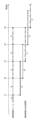
図3は、本実施形態に係る補強情報の各フレームと補強情報の有効期間との関係を示す図である。図3に示す時刻t1、t2、t3、t4及びt5は、一定時間毎の区切りであり、図示されていないが、本実施形態に係る自己位置取得装置1の動作中は、t5以降も中断することなく続いている。
Figure 3 is a diagram showing the relationship between each frame of reinforcement information and the validity period of the reinforcement information according to this embodiment. Times t1, t2, t3, t4, and t5 shown in Figure 3 are divisions of fixed time periods, and although not shown, operation of the self-
特定の測位衛星は、互いに異なる固有の補強情報を所定時間毎に順次送信している。各補強情報は、互いに切れ目なく連続するように送信されている。各補強情報は、互いに同じ一定のフレーム長さを有しており、測位装置2が1フレーム分の受信に要するフレーム受信時間も互いに同じ長さである。例えば本実施形態では図3に示すように、測位装置2は、特定の測位衛星から補強情報A、B、C、D及びEを連続して受信しており、特に図示していないがE以降も中断することなく続いて補強情報を受信している。測位装置2では、先の補強情報の受信が完了すると、連続して次の補強情報の受信が開始されるようになっている。図3に示す例では、時刻t1に補強情報Aの受信が完了すると、同時刻t1において補強情報Bの受信が開始される。
Specific positioning satellites transmit unique reinforcement information that differs from one another at predetermined time intervals. Each piece of reinforcement information is transmitted so that it is continuous with no breaks. Each piece of reinforcement information has the same fixed frame length, and the frame reception time required for the
補強情報は、補強情報の1フレーム分の受信が完了した時刻からその補強情報の有効期間が開始される。補強情報は、ある補強情報の有効期間とその次の補強情報の有効期間とが一部重なるようにその有効期間の長さが設定されている。例えば本実施形態では、補強情報の有効期間は、1フレームを受信するフレーム受信時間の2倍の長さに設定されており、測位装置2によって1フレーム分が連続して正常に受信できている補強情報の場合、受信を完了した時刻から2フレーム分のフレーム受信時間だけ先の時刻までの間となる。
The validity period of the reinforcement information begins from the time when reception of one frame of the reinforcement information is completed. The length of the validity period of the reinforcement information is set so that the validity period of one piece of reinforcement information overlaps partially with the validity period of the next piece of reinforcement information. For example, in this embodiment, the validity period of the reinforcement information is set to be twice as long as the frame reception time for receiving one frame, and in the case of reinforcement information in which one frame is successfully received continuously by the
図3に示す例では、補強情報Aの有効期間A’の後半と、補強情報Bの有効期間B’の前半とが重なっている。補強情報Aの有効期間A’は、時刻t1から時刻t3までの時間となり、次ぐ補強情報Bの有効期間B’は、時刻t2から時刻t4までの時間となる。自己位置取得装置1では、補強情報の有効期間と次の補強情報の有効期間とが重なっている部分については、何れの補強情報も受信が完了していることを前提に、より新鮮な情報である次の補強情報を利用する。
In the example shown in FIG. 3, the latter half of the validity period A' of reinforcing information A overlaps with the first half of the validity period B' of reinforcing information B. The validity period A' of reinforcing information A is from time t1 to time t3, and the validity period B' of the subsequent reinforcing information B is from time t2 to time t4. In the self-
図3に示す例では、阻害期間はなく、補強情報の利用ができない期間は発生していない。したがって、測位方式切替部104から測位方式の切り替え指示は出力されず、測位装置2の測位方式として第1測位方式が維持される。
In the example shown in FIG. 3, there is no inhibition period, and no period occurs during which the reinforcement information cannot be used. Therefore, no instruction to switch the positioning method is output from the positioning
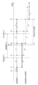
図4Aと図4Bは、本実施形態に係る補強情報の受信が阻害された場合における補強情報の有効期間の状態を時系列順に示す図である。 Figures 4A and 4B are diagrams showing the state of the validity period of the reinforcement information in chronological order when reception of the reinforcement information in this embodiment is interrupted.
本実施形態に係る測位方式切替部104の(1)第2測位方式に切り替えるパターンの場合、及び、(2)第1測位方式を維持するパターンの動作を、図4Aと図4Bを用いて以下に詳述する。
The operation of the positioning
(1)第2測位方式に切り替えるパターン
図4Aに示す例では、補強情報Bの受信途中で阻害期間t10が開始され、補強情報Dの受信途中で阻害期間t10が終了している。したがって、測位装置2は、補強情報B、C、Dを利用できず、阻害期間t10が終了した後に受信を開始した補強情報Eの受信完了時刻t5から補強情報Eを利用することができる。これにより、補強情報Aの有効期間A’が終了する時刻t3から補強情報Eの利用が開始できる時刻t5までの間、補強情報を利用できない期間が発生する。
(1) Pattern of switching to the second positioning method In the example shown in Fig. 4A, the inhibition period t10 starts in the middle of receiving the reinforcing information B, and ends in the middle of receiving the reinforcing information D. Therefore, the
図4Aに示す例の場合、測位方式切替部104によって、阻害期間t10があると判定され、阻害期間の開始時刻t11よりも前に受信を完了する補強情報Aが特定される。そして、その特定された補強情報Aの有効期間が終了する時刻t3が第1時刻tAとして特定される。次いで、阻害期間t10の終了時刻t12以降に受信を開始する補強情報Eが特定され、補強情報Eの有効期間開始時刻t5が第2時刻tBとして特定される。そして、測位方式切替部104によって、第1時刻tA(時刻t3)までに第2時刻tB(時刻t5)が到来しないので、測位装置2によって順次受信される補強情報のいずれも利用できない期間が発生すると判断され、測位装置2の測位方式を第1測位方式から第2測位方式に事前に切り替える指示が測位装置2に出力される。
In the example shown in FIG. 4A, the positioning
これにより、測位装置2は、第1時刻tA(時刻t3)が到来する前の時刻t3pにおいて、測位方式を第1測位方式から第2測位方式に切り替え、第2時刻tB(時刻t5)まで第2測位方式によって測位を行う。
As a result, the
好ましくは、測位装置2は、第1時刻tA(時刻t3)よりも前のタイミングである時刻tpにおいて、測位方式切替部104の指示に従って第2測位方式に切り替えるための事前処理(通信リンクの確立など)を行う。
Preferably, the
また、測位方式切替部104によって、第2時刻tB(時刻t5)からは補強情報が利用できる期間であるので、測位装置2の測位方式を第2測位方式から第1測位方式に戻す指示が測位装置2に出力される。
In addition, since the period from the second time tB (time t5) onwards is a period in which the reinforcement information can be used, the positioning
これにより、測位装置2は、第2時刻tB(時刻t5)において、測位方式を第2測位方式から第1測位方式に切り替え、第2時刻tB(時刻t5)から第1測位方式によって測位を行う。
As a result, the
(2)第1測位方式を維持するパターン
図4Bに示す例では、補強情報Bの受信途中で阻害期間t10が開始され、補強情報Bの受信途中で阻害期間t10が終了している。したがって、測位装置2は、補強情報Bを利用できず、阻害期間t10が終了した後に受信を開始した補強情報Cの受信完了時刻t3から補強情報Cを利用することができる。これにより、補強情報Aの有効期間A’が終了する時刻と補強情報Cの利用が開始できる時刻がともに時刻t3となる。
(2) Pattern of maintaining the first positioning method In the example shown in Fig. 4B, the inhibition period t10 starts in the middle of receiving the reinforcement information B, and the inhibition period t10 ends in the middle of receiving the reinforcement information B. Therefore, the
図4Bに示す例の場合、測位方式切替部104によって、瞬間的な阻害期間t10があると判定され、阻害期間t10の開始時刻t11よりも前に受信を完了する補強情報Aが特定される。そして、その特定された補強情報Aの有効期間が終了する時刻t3が第1時刻tAとして特定される。次いで、阻害期間t10の終了時刻t12以降に受信を開始する補強情報Cが特定され、補強情報Cの有効期間開始時刻t3が第2時刻tBとして特定される。そして、測位方式切替部104によって、第1時刻tA(時刻t3)までに第2時刻tB(時刻t3)が到来するので、測位装置2によって順次受信される複数の補強情報がそれぞれ有する有効期間同士の連続性が確保できると判断され、第1測位方式を維持する指示が測位装置2に出力される。これにより、測位装置2は、第1測位方式を維持したまま測位を行う。
In the example shown in FIG. 4B, the positioning
以上のように、本実施形態に係る自己位置取得装置1は、自車両に搭載されており、測位衛星から受信した測位電波の受信情報及び受信情報を補強する補強情報に基づいて測位を行う第1測位方式と、受信情報及びネットワークを介して測位サーバから受信した測位補助情報に基づいて測位を行う第2測位方式とを、切り替える。本実施形態に係る自己位置取得装置1は、第1測位方式において精度が低下する阻害期間、及び、補強情報の有効期間に基づいて、第1測位方式を第2測位方式に切り替える。
As described above, the self-
本実施形態に係る自己位置取得装置1(図1)は、阻害期間前後において利用可能な補強情報が連続して利用できるか否か、すなわち阻害期間前後において利用可能な補強情報の有効期間が連続しているか否か(図2のS106)に基づいて、第1測位方式を第2測位方式に切り替える。本実施形態に係る自己位置取得装置1は、阻害期間前後において利用可能な補強情報の有効期間が連続している場合(図2のS106のYes、図3、図4B)には、続けて第1測位方式によって測位可能なので、第1測位方式から第2測位方式への切り替えは行われず、第1測位方式が維持される(図2のS110)。これにより、本実施形態に係る自己位置取得装置1は、第1測位方式から第2測位方式への無駄な切り替えが起こることを抑制することができる。また、本実施形態に係る自己位置取得装置1は、阻害期間前後において利用可能な補強情報の有効期間が連続していない場合(図2のS106のNo、図4A)には、阻害期間前において利用可能な補強情報の有効期間が終了するタイミングで第1測位方式から第2測位方式に切り替え(図2のS107)、阻害期間後において利用可能な補強情報の有効期間が開始するタイミングで第2測位方式から第1測位方式に切り替える(図2のS108)。これにより、本実施形態に係る自己位置取得装置1は、測位精度を低下させずに高精度な自己位置取得を維持することができるとともに、第2測位方式による通信料などの無駄なコストの発生を防ぐことができる。したがって、本実施形態に係る自己位置取得装置1によれば、コストを抑えながら安定して高精度測位を行うことが可能となる。
The self-location acquisition device 1 (FIG. 1) according to the present embodiment switches from the first positioning method to the second positioning method based on whether the available reinforcement information is continuously available before and after the inhibition period, that is, whether the validity period of the available reinforcement information is continuous before and after the inhibition period (S106 in FIG. 2). When the validity period of the available reinforcement information is continuous before and after the inhibition period (Yes in S106 in FIG. 2, FIG. 3, FIG. 4B), the self-
更に、本実施形態に係る自己位置取得装置1は、阻害期間及び補強情報の有効期間に基づいて、阻害期間よりも前に受信を完了する補強情報の有効期間が終了する時刻である第1時刻tAと、阻害期間終了後に受信を開始する補強情報の有効期間開始時刻である第2時刻tBと、を特定する。本実施形態に係る自己位置取得装置1は、第1時刻tAと第2時刻tBとを比較して、第1測位方式を第2測位方式に切り替える。
Furthermore, the self-
本実施形態に係る自己位置取得装置1(図1)は、第1時刻tAと第2時刻tBを特定すること(図2のS104及びS105)によって、阻害期間前後において利用可能な補強情報の有効期間を具体的に把握することができるので、第1測位方式によって測位可能な期間(図3、図4A、図4B)を正確に把握にすることができる。これに加えて、本実施形態に係る自己位置取得装置1は、第1測位方式によって測位不可能な期間も正確に把握することができるので、第1測位方式によって測位不可能な期間を第2測位方式によって測位する期間(図4A)とすることができる。これにより、本実施形態に係る自己位置取得装置1は、第1測位方式から第2測位方式への無駄な切り替えがより発生し難く、且つ、測位精度を低下させずに高精度な自己位置取得を維持することが容易となる。したがって、本実施形態に係る自己位置取得装置1によれば、コストを抑えながら安定して高精度測位を行うことが更に可能となる。
The self-
更に、本実施形態に係る自己位置取得装置1は、第1時刻tAまでに第2時刻tBが到来する場合には、第1測位方式を維持し、第1時刻tAよりも後に第2時刻tBが到来する場合には、第2測位方式に切り替える。
Furthermore, the self-
本実施形態に係る自己位置取得装置1(図1)は、第1時刻tAの到来までに第2時刻tBが到来すること(図2のS106のYes、図3、図4B)によって、阻害期間前後において利用可能な補強情報の有効期間が連続する状態を具体的に示している。また、本実施形態に係る自己位置取得装置1は、第1時刻tAの到来よりも後に第2時刻tBが到来すること(図2のS106のNo、図4A)によって、阻害期間前後において利用可能な補強情報の有効期間が連続しない状態を具体的に示している。本実施形態に係る自己位置取得装置1は、第1時刻tA及び第2時刻tBの比較指標を具体的に示すことによって、第1測位方式を維持する場合(図2のS110)と、第1測位方式から第2測位方式に切り替える場合(図2のS107)と、を正確に区別することができる。これにより、第1測位方式から第2測位方式への無駄な切り替えが起こることを抑制することが容易となる。したがって、本実施形態に係る自己位置取得装置1によれば、コストを抑えながら安定して高精度測位を行うことが更に可能となる。
The self-
更に、本実施形態に係る自己位置取得装置1は、自車両の上空を遮蔽される遮蔽期間を阻害期間とする。
Furthermore, the self-
本実施形態に係る自己位置取得装置1(図1)は、自車両の測位が遮られる障害物(阻害要因)が自車両の上空に存在しているものであることを明確にする。これにより、本実施形態に係る自己位置取得装置1は、適切な対象を障害物(阻害要因)として捉えることができるので、阻害期間を算出すること(図2のS102)が容易となる。この結果、本実施形態に係る自己位置取得装置1は、第1時刻tA及び第2時刻tBを阻害期間及び補強情報の有効期間から特定すること(図2のS104及びS105)も容易となるので、第1測位方式によって測位するのか、または、第2測位方式によって測位するのかを判断することも容易となる。したがって、本実施形態に係る自己位置取得装置1によれば、コストを抑えながら安定して高精度測位を行うことが更に可能となる。
The self-
また、本実施形態に係る自己位置取得装置1は、外界認識装置3の認識対象をより簡素化することができる。これにより、処理負荷を抑えることができるので阻害要因情報を取得する速度を向上することができるとともに、より廉価なハードウェアによって自己位置取得装置1を構築することができる。
In addition, the self-
[第2実施形態]
次に、図5、図6及び図7を用いて、第2実施形態に係る自己位置取得装置1について説明する。第2実施形態に係る自己位置取得装置1において、第1実施形態に係る自己位置取得装置1と同様の構成及び動作については説明を省略する。
[Second embodiment]
Next, the self-
第2実施形態に係る自己位置取得装置1は、内界認識装置4、移動量算出部111、状態取得部112、及び、算出方式切替部113を更に備えている点において、第1実施形態に係る自己位置取得装置1と相違する。
The self-
また、第1実施形態に係る阻害期間算出部102は、補強情報を送信する特定の測位衛星と受信アンテナとの間の対象物に対して、阻害期間を算出する機能を有していることを説明した。これに加えて、第2実施形態に係る阻害期間算出部102は、特定の測位衛星以外の測位衛星についての阻害予測をする機能を含んでいてもよい。すなわち、第2実施形態に係る阻害期間算出部102は、個々の測位衛星からそれぞれの仰角及び方位角を電波に含まれる受信情報から取得することができる。これにより、第2実施形態に係る阻害期間算出部102は、補強情報を送信する特定の測位衛星と同様に、特定の測位衛星以外の測位衛星についても阻害期間を個別に算出することが可能である。
Also, it has been explained that the inhibition
第1実施形態に係る自己位置取得装置1は、阻害されていない場合は、第1測位方式によって車両の自己位置を取得する。一方、阻害期間内においては、第1実施形態に係る自己位置取得装置1は、第1時刻tAと第2時刻tBを比較して、第1時刻tAよりも後に第2時刻tBが到来する場合に第2測位方式によって車両の自己位置を取得する。この場合、車両の自己位置は、過去の測位結果に対して自車移動量を補間したものが推定された自己位置として位置取得部101に取得される。よって、阻害期間内における自己位置の取得は、第2測位方式を用いていても阻害されていない場合に比べて精度が落ちるおそれがある。
When the vehicle is not obstructed, the self-
そこで、第2実施形態に係る自己位置取得装置1は、阻害期間内において、車両の自己位置を推定するための自車移動量を、未だ阻害されていない測位衛星を用いた衛星測位に基づいて算出するか、または、ホイールオドメトリ法に基づいて算出することによって、上記課題を解決する。
The self-
以下、第2実施形態に係る自己位置取得装置1が車両の自己位置を推定するための自車移動量を如何にして算出するのか説明する。
The following describes how the self-
第2実施形態に係る自己位置取得装置1は、阻害期間算出部102において個々の測位衛星の阻害期間を個別に算出可能なこと、及び、位置取得部101において自車両の将来の走行経路が認識可能なこと、を前提に未だ阻害されていない測位衛星に基づいて自車移動量を算出する。この算出方式を第1算出方式と呼ぶ。第1算出方式としては、観測可能であり、阻害期間までに猶予もあり、且つ自車方位に則した測位衛星を選択し、選択した測位衛星に基づいて自車移動量を算出する。選択する測位衛星としては、観測できている測位衛星のうち、阻害開始までの時間が所定値Tthr以上であり、且つ走行経路に基づく自車進行方位Dvehicleと測位衛星の方位角Dsatが所定の範囲内Dthrにあるものを選択する。すなわち、選択する測位衛星としては、下記数式3に示すように、進行方向に対して角度が±Dthr/2以内、すなわち進行方向の前後方向にある測位衛星を選択することが好ましく、下記数式4に示すように、進行方向に対して角度がDthr/2以内、すなわち進行方向の後方にある測位衛星を選択することがより好ましい。なお、ここで“%”は剰余記号を意味している。
[数3]
|Dvehicle-Dsat|%180<Dthr
[数4]
Dvehicle-Dsat%180<Dthr
The self-
[Equation 3]
|Dvehicle-Dsat|%180<Dthr
[Equation 4]
Dvehicle-Dsat%180<Dthr
第1算出方式としては、例えばドップラーシフトに基づく算出方法や、搬送波位相差に基づく算出方法などの特定の1つの測位衛星と自車(観測者)との間の速度を算出する公知の方法を用いることが好ましい。また、第1算出方式としては、一部の衛星からの電波にマルチパスがあっても安定的に速度を求めるために、多数の観測可能な衛星と自車との間の速度を算出し、算出した複数の算出結果の最小二乗を用いて自車速度と移動方位を算出してもよい。 As the first calculation method, it is preferable to use a known method for calculating the speed between one specific positioning satellite and the vehicle (observer), such as a calculation method based on the Doppler shift or a calculation method based on the carrier phase difference. In addition, as the first calculation method, in order to stably determine the speed even if there is multipath in the radio waves from some satellites, the speed between multiple observable satellites and the vehicle may be calculated, and the vehicle speed and traveling direction may be calculated using the least squares of the multiple calculation results.
図5は、測位衛星に基づいて自車移動量を算出する際の、測位衛星の選択に関する説明図である。 Figure 5 is an explanatory diagram regarding the selection of positioning satellites when calculating the vehicle's movement amount based on positioning satellites.
第1算出方式の算出方法を、図5を用いて模式的に説明する。自車両10が図中上向きに走行しており、歩道橋11が前方にあり、ビル12が右側にある環境において、測位衛星S1~S4が自車両10の周囲に存在している状態を想定する。ここでドップラーシフトに基づく方法と、搬送波位相差に基づく方法のいずれかを用いて自車速度を算出する際に、選択される測位衛星について説明する。自車両10から観測できている測位衛星である必要があるという観点から、測位衛星S4は、ビル12に阻害されているため選択候補から除外される。近い将来に阻害される測位衛星S1は、阻害開始までの時間がTthr以上という制約を満たさないおそれがあるため選択候補から除外される。測位衛星S3は、自車進行方位と測位衛星の方位角がDthr以内という制約を満たさないおそれがあるため選択候補から除外される。自車両10の進行方向の後方に存在している測位衛星S2は、上述の制約全てを満たす。したがって、第1算出方式は、測位衛星S2に基づいて自車速度を算出することで、精度の高い速度を得ることができる。ここでは、1衛星のみ利用する例で記載したが、条件を満たす測位衛星が複数ある場合には、それらを用いて最小二乗法などで速度を算出してもよい。
The calculation method of the first calculation method is explained using FIG. 5. Assume that the
上述した条件に当てはまる測位衛星が無かった場合、車両のステアリング角度やタイヤの回転量から自車両の相対的な動きを推定する公知のホイールオドメトリ法に基づいて自車移動量を算出する。この算出方式を第2算出方式と呼ぶ。 If there are no positioning satellites that meet the above conditions, the vehicle movement amount is calculated based on the well-known wheel odometry method, which estimates the relative movement of the vehicle from the vehicle's steering angle and tire rotation amount. This calculation method is called the second calculation method.
図6は、第2実施形態に係る自己位置取得装置1を示すブロック図である。
Figure 6 is a block diagram showing the self-
第2実施形態に係る自己位置取得装置1には、図6に示すように、内界認識装置4が接続されている。また、第2実施形態に係る自己位置取得装置1は、図6に示すように、移動量算出部111、状態取得部112、及び算出方式切替部113を備えている。
As shown in FIG. 6, an internal recognition device 4 is connected to the self-
内界認識装置4は、自車両に搭載されており、自車両の挙動を計測する。内界認識装置4としては、ミリ波Radar、車輪速パルスセンサ、加速度センサ及び角速度センサといった自車両の速度を測るセンサ類、並びに、横滑り防止装置(ESC)及び慣性計測装置(IMU)といった自車両の姿勢を測るセンサ装置を意図している。内界認識装置4は、自己位置取得装置1の外部に備えられていてもよく、自己位置取得装置1内に備えられていてもよい。内界認識装置4は、取得した自車両の挙動に関する情報(以下、自車挙動情報ともいう)を、自己位置取得装置1に送信する。
The internal environment recognition device 4 is mounted on the vehicle and measures the behavior of the vehicle. The internal environment recognition device 4 is intended to include sensors that measure the speed of the vehicle, such as a millimeter wave radar, a wheel speed pulse sensor, an acceleration sensor, and an angular velocity sensor, as well as sensor devices that measure the attitude of the vehicle, such as an electronic stability control (ESC) and an inertial measurement unit (IMU). The internal environment recognition device 4 may be provided outside the self-
移動量算出部111は、測位衛星に基づいた第1算出方式、または、ホイールオドメトリ法に基づいた第2算出方式、の何れかの算出方式を用いて自車移動量を算出する。内界認識装置4から得られる自車挙動情報は、ホイールオドメトリ法を行うのに用いられる。
The movement
状態取得部112は、内界認識装置4から送信された自車挙動情報を取得する。状態取得部112は、自車挙動情報に基づいてホイールオドメトリ法の精度状態を判断する。ホイールオドメトリ法の精度状態としては、所定時間内に一度もタイヤトルクが急変しない場合は、ホイールオドメトリ法の精度状態が良好な状態であると判断する。一方、所定時間内にタイヤトルクが複数回にわたって急変する場合や、所定時間タイヤトルクが通常よりも減少している場合は、路面に凹凸が多い、または、路面が滑りやすいことが推定され、ホイールオドメトリ法の精度状態が良好でない状態であると判断する。状態取得部112は、判断したホイールオドメトリの精度状態の情報を算出方式切替部113に送信する。
The
上述の判断例としては、横滑り防止装置が瞬間的なタイヤトルクの変化を観測し、或いは、加速度センサまたは車速センサが路面の凹凸を検出し、この検出結果に基づいてホイールオドメトリ法の精度状態が良好でない状態であると状態取得部112が判断する。また例えば、車輪速パルスセンサの出力とミリ波Radarによる対地車速情報を照合し、これらの異種センサ間の整合性に基づいて、ホイールオドメトリ法の精度状態を状態取得部112が判断してもよい。同様に、慣性計測装置のセンサ出力の積算値から得られる自車移動量や角度変化量と、車輪速パルスセンサ及び舵角センサから得られる自車移動量や角度変化量と、の整合性に基づいて、ホイールオドメトリ法の精度状態を状態取得部112が判断してもよい。
As an example of the above-mentioned judgment, the anti-skid device observes an instantaneous change in tire torque, or an acceleration sensor or a vehicle speed sensor detects unevenness on the road surface, and the
算出方式切替部113は、状態取得部112から取得したホイールオドメトリ法の精度状態の情報、及び、第2実施形態に係る阻害期間算出部102から得られる個々の測位衛星の仰角及び方位などの情報に基づいて、自車の現状に則した自車移動量の算出方式に切り替える。換言すると、算出方式切替部113は、ホイールオドメトリ法の精度、及び、阻害の程度を考慮して、第1算出方式または第2算出方式の何れかに切り替える。
The calculation
図7は、図6に示す算出方式切替部113による自車移動量算出方式の切り替えにおける判断処理の一例を示すフローチャートである。
Figure 7 is a flowchart showing an example of the determination process for switching the vehicle movement amount calculation method by the calculation
図7に示すように、算出方式切替部113による自車移動量算出方式の切り替えにおける判断処理は大まかには以下の通りである。
As shown in FIG. 7, the determination process performed by the calculation
まず、算出方式切替部113は、自車進行方向後方に自車移動量の算出に用いることができる測位衛星が所定数存在するかを判定する。自車進行方向後方に自車移動量の算出に用いることができる測位衛星が所定数存在する場合、算出方式切替部113は、算出方式を第1算出方式に切り替える。
First, the calculation
自車進行方向後方に自車移動量の算出に用いることができる測位衛星が所定数存在しなかった場合、次いで、算出方式切替部113は、ホイールオドメトリ法の精度状態が良好かどうかを判定する。ホイールオドメトリ法の精度状態が良好な場合、算出方式切替部113は、算出方式を第2算出方式に切り替える。
If there are not a certain number of positioning satellites that can be used to calculate the vehicle's movement amount behind the vehicle in the traveling direction, the calculation
ホイールオドメトリ法の精度状態が不良な場合、次いで、算出方式切替部113は、算出方式を第1算出方式に切り替える。
If the accuracy state of the wheel odometry method is poor, then the calculation
ホイールオドメトリ法の精度状態が第2算出方式による自車移動量の算出に耐え得る状態の場合、次いで、算出方式切替部113は、自車進行方向のうち前後方向に自車移動量の算出に用いることができる測位衛星が所定数存在するかを判定する。自車進行方向のうち前後方向に自車移動量の算出に用いることができる測位衛星が所定数存在する場合、算出方式切替部113は、算出方式を第1算出方式に切り替える。自車進行方向のうち前後方向に自車移動量の算出に用いることができる測位衛星が所定数存在しなかった場合、算出方式切替部113は、算出方式を第2算出方式に切り替える。
If the accuracy state of the wheel odometry method is in a state that can withstand calculation of the host vehicle movement amount using the second calculation method, the calculation
算出方式切替部113による自車移動量算出方式の切り替えにおける判断処理は具体的には以下の通りである。
Specifically, the determination process performed by the calculation
算出方式切替部113は、以下の(a)~(c)全ての条件に適合する測位衛星の数N1をカウントする(ステップS201)。
(a)自車両から観測可能であること。
(b)阻害開始までの時間が所定値Tthr以上であること。
(c)方位角が自車進行方向に対してDthr/2以内であること。
The calculation
(a) It is observable from the vehicle.
(b) The time until the onset of inhibition is equal to or greater than a predetermined value Tthr.
(c) The azimuth angle is within Dthr/2 with respect to the vehicle's traveling direction.
算出方式切替部113は、ステップS201においてカウントした測位衛星の数N1が所定の第1閾値Nsat1以上かどうか判定する(ステップS202)。なお、カウントした測位衛星の数N1の数値が大きいほど、算出して得られる自車移動量の精度が上がる。算出方式切替部113は、測位衛星の数N1が所定の第1閾値Nsat1未満の場合に(ステップS202でNo)、ステップS203に移行する。算出方式切替部113は、測位衛星の数N1が所定の第1閾値Nsat1以上の場合に(ステップS202でYes)、ステップS208に移行する。
The calculation
算出方式切替部113は、状態取得部112から取得したホイールオドメトリ法の精度状態の指標Indが所定の第1閾値Det1未満かどうか判定する(ステップS203)。なお、ホイールオドメトリ法の精度状態の指標Indの数値が小さいほど、ホイールオドメトリ法の精度状態が良好な状態であると言える。算出方式切替部113は、ホイールオドメトリ法の精度状態の指標Indが所定の第1閾値Det1未満の場合に(ステップS203でYes)、ステップS207に移行する。算出方式切替部113は、ホイールオドメトリ法の精度状態の指標Indが所定の第1閾値Det1以上の場合に(ステップS203でNo)、ステップS204に移行する。
The calculation
算出方式切替部113は、状態取得部112から取得したホイールオドメトリ法の精度状態の指標Indが所定の第2閾値Det2未満かどうか判定する(ステップS204)。なお、ステップS204におけるホイールオドメトリ法の精度状態の指標Indは、ステップS203におけるホイールオドメトリ法の精度状態の指標Indと同一である。したがって、ホイールオドメトリ法の精度状態の指標Indは、所定の第1閾値Det1以上である。算出方式切替部113は、ホイールオドメトリ法の精度状態の指標Indが所定の第2閾値Det2未満の場合に(ステップS204でYes)、ステップS205に移行する。算出方式切替部113は、ホイールオドメトリ法の精度状態の指標Indが所定の第2閾値Det2以上の場合に(ステップS204でNo)、ステップS208に移行する。なお、所定の第2閾値Det2は、ホイールオドメトリ法の精度状態が第2算出方式による自車移動量の算出に耐え得るか否かの境目となる値である。
The calculation
算出方式切替部113は、以下の(a)、(b)及び(d)全ての条件に適合する測位衛星の数N2をカウントする(ステップS205)。
(a)自車から観測可能であること。
(b)阻害開始までの時間が所定値Tthr以上であること。
(d)方位角が自車進行方向に対して±Dthr/2以内であること。
The calculation
(a) It is observable from the vehicle.
(b) The time until the onset of inhibition is equal to or greater than a predetermined value Tthr.
(d) The azimuth angle is within ±Dthr/2 with respect to the vehicle's traveling direction.
算出方式切替部113は、ステップS205においてカウントした測位衛星の数N2が所定の第2閾値Nsat2以上かどうか判定する(ステップS206)。なお、カウントした測位衛星の数N2の数値が大きいほど、算出して得られる自車移動量の精度が上がる。算出方式切替部113は、測位衛星の数N2が所定の第2閾値Nsat2未満の場合に(ステップS206でNo)、ステップS207に移行する。算出方式切替部113は、測位衛星の数N2が所定の第2閾値Nsat2以上の場合に(ステップS206でYes)、ステップS208に移行する。
The calculation
算出方式切替部113は、ホイールオドメトリ法の精度状態の指標Indが所定の第1閾値Det1未満の場合(ステップS203でYes)、又は、測位衛星の数N2が所定の第2閾値Nsat2未満の場合に(ステップS206でNo)、算出方式を第2算出方式に切り替える(ステップS207)。
When the index Ind of the accuracy state of the wheel odometry method is less than a predetermined first threshold value Det1 (Yes in step S203), or when the number N2 of positioning satellites is less than a predetermined second threshold value Nsat2 (No in step S206), the calculation
算出方式切替部113は、測位衛星の数N1が所定の第1閾値Nsat1以上の場合(ステップS202でYes)、ホイールオドメトリ法の精度状態の指標Indが所定の第2閾値Det2以上の場合(ステップS204でNo)、又は、測位衛星の数N2が所定の第2閾値Nsat2以上の場合に(ステップS206でYes)、算出方式を第1算出方式に切り替える(ステップS208)。
The calculation
なお、ステップS203及びステップS204において、ホイールオドメトリ法の精度状態の指標Indに対する比較対象として規定する第1閾値Det1及び第2閾値Det2の数値は、変更可能である。具体的には、内界認識装置4の検知前に、外界認識装置3が路面状態を測定し、測定した路面状態の情報を自己位置取得装置1に送信する。算出方式切替部113は、外界認識装置3から送信された路面状態の情報に基づいて、将来のホイールオドメトリ法の精度状態を予測する。算出方式切替部113は、将来のホイールオドメトリ法の精度状態が良好でない状態になり得ると判断した場合、第1閾値Det1及び第2閾値Det2の数値を小さく変更する。
In addition, in steps S203 and S204, the values of the first threshold Det1 and the second threshold Det2, which are defined as comparison targets for the index Ind of the accuracy state of the wheel odometry method, can be changed. Specifically, before detection by the internal recognition device 4, the
以上のように、第2実施形態に係る自己位置取得装置1は、自車両に搭載された内界認識装置4によってホイールオドメトリ法の精度状態に関する情報を取得し、阻害期間内において、自己位置を推定するための車両の移動量を算出する算出方式として、測位衛星の数に関する以下の数式5、及び、ホイールオドメトリ法の精度状態に関する以下の数式6に応じて、数式5が成り立つ場合には、測位衛星に基づいて車両の移動量を算出する第1算出方式に切り替え、数式5が成り立たず、もしくは数式6が成り立つ場合には、ホイールオドメトリ法に基づいて車両の移動量を算出する第2算出方式に切り替える。
[数5]
N1≧Nsat1
N1:以下の全ての条件に適合する衛星数
観測できている測位衛星
阻害開始までの時間が所定値(Tthr)以上
走行経路に基づく自車進行方位(Dvehicle)、測位衛星の方位角(D
sat)、及び、所定の範囲内(Dthr)が以下の関係にあたる測位衛星
Dvehicle-Dsat%180<Dthr
ここで、“%”は剰余記号を意味する
Nsat1:衛星数に関する所定の第1閾値
[数6]
Ind<Det1
Ind:ホイールオドメトリ法の精度状態の指標
Det1:ホイールオドメトリ法の精度状態に関する所定の第1閾値
As described above, the self-
[Equation 5]
N1 ≧ Nsat1
N1: The number of satellites that meet all of the following conditions: Positioning satellites that can be observed Time until the start of obstruction is greater than or equal to a specified value (Tthr) Vehicle heading based on the driving route (Dvehicle), azimuth angle of the positioning satellite (D
sat) and within a specified range (Dthr) have the following relationship: Dvehicle-Dsat%180<Dthr
where "%" means a modulus symbol. Nsat1: a predetermined first threshold value for the number of satellites [Equation 6]
Ind < Det1
Ind: An index of the accuracy state of the wheel odometry method Det1: A predetermined first threshold value for the accuracy state of the wheel odometry method
第2実施形態に係る自己位置取得装置1(図6)は、阻害期間内において、公知の測定装置及び公知の測定方法を用いて、上述の数式5(図7のS201及びS202)及び数式6(図7のS203)によって、観測可能な測位衛星(図5のS2)、及び、ホイールオドメトリ法の何れか適切な方に基づいて車両の自己位置を推定するための自車移動量を正確に算出すること(図7のS207または7のS208)ができる。これにより、第2実施形態に係る自己位置取得装置1は、阻害期間内においても過去に算出された測位結果に対して算出した自車移動量を補間することによって、精度のよい自己位置取得が可能となる。したがって、本実施形態に係る自己位置取得装置1によれば、コストを抑えながら安定して高精度測位を行うことが更に可能となる。
The self-location acquisition device 1 (FIG. 6) according to the second embodiment can accurately calculate the vehicle movement amount (S207 or S208 in FIG. 7) for estimating the vehicle's self-location based on either an observable positioning satellite (S2 in FIG. 5) or the wheel odometry method, whichever is appropriate, using a known measurement device and a known measurement method during the inhibition period, by using the above-mentioned formula 5 (S201 and S202 in FIG. 7) and formula 6 (S203 in FIG. 7). As a result, the self-
更に、第2実施形態に係る自己位置取得装置1は、上述の数式5及び数式6が成り立たない場合において、ホイールオドメトリ法の精度状態に関する以下の数式7、及び、測位衛星の数に関する以下の数式8に応じて、数式7が成り立つ場合には、第2算出方式に切り替え、数式7が成り立たず、もしくは数式8が成り立つ場合には、第1算出方式に切り替える。
[数7]
Det1≦Ind<Det2
Ind:ホイールオドメトリ法の精度状態の指標
Det1:ホイールオドメトリ法の精度状態に関する所定の第1閾値
Det2:ホイールオドメトリ法の精度状態に関する所定の第2閾値
[数8]
N2≧Nsat2
N2:以下の全ての条件に適合する衛星数
観測できている測位衛星
阻害開始までの時間が所定値(Tthr)以上
走行経路に基づく自車進行方位(Dvehicle)、測位衛星の方位角(D
sat)、及び、所定の範囲内(Dthr)が以下の関係にあたる測位衛星
|Dvehicle-Dsat|%180<Dthr
ここで、“%”は剰余記号を意味する
Nsat2:衛星数に関する所定の第2閾値
Furthermore, when the above-mentioned
[Equation 7]
Det1≦Ind<Det2
Ind: An index of the accuracy state of the wheel odometry method Det1: A predetermined first threshold value related to the accuracy state of the wheel odometry method Det2: A predetermined second threshold value related to the accuracy state of the wheel odometry method
[Number 8]
N2 ≧ Nsat2
N2: The number of satellites that meet all of the following conditions: Positioning satellites that can be observed Time until the start of obstruction is greater than or equal to a specified value (Tthr) Vehicle heading based on the driving route (Dvehicle), azimuth angle of the positioning satellite (D
sat) and a positioning satellite within a specified range (Dthr) that satisfies the following relationship: |Dvehicle-Dsat|%180<Dthr
where "%" is a modulus symbol. Nsat2: a second predetermined threshold value for the number of satellites.
第2実施形態に係る自己位置取得装置1(図6)は、阻害期間内において、公知の測定装置及び公知の測定方法を用いて、上述の数式5(図7のS201及びS202)及び数式6(図7のS203)よりも許容範囲を広くした数式7(図7のS204)及び数式8(図7のS205及びS206)によって、観測可能な測位衛星、及び、ホイールオドメトリ法の何れか好ましい方に基づいて車両の自己位置を推定するための自車移動量を算出すること(図7のS207または7のS208)ができる。これにより、第2実施形態に係る自己位置取得装置1は、阻害期間内においても過去に算出された測位結果に対して算出した自車移動量を補間することによって、精度のよい自己位置取得をすることが容易となる。したがって、本実施形態に係る自己位置取得装置1によれば、コストを抑えながら安定して高精度測位を行うことが更に可能となる。
The self-location acquisition device 1 (FIG. 6) according to the second embodiment can calculate the vehicle movement amount (S207 or S208 in FIG. 7) for estimating the vehicle's own position based on the observable positioning satellites and the wheel odometry method, whichever is more preferable, by using a known measurement device and a known measurement method during the inhibition period, using Equation 7 (S204 in FIG. 7) and Equation 8 (S205 and S206 in FIG. 7), which have a wider tolerance range than Equation 5 (S201 and S202 in FIG. 7) and Equation 6 (S203 in FIG. 7). This makes it easier for the self-
更に、第2実施形態に係る自己位置取得装置1は、自車両に搭載された外界認識装置3によって得られる路面状態に基づいてホイールオドメトリ法の精度状態に関する所定の第1閾値を変更する。
Furthermore, the self-
第2実施形態に係る自己位置取得装置1(図6)は、算出方式切替部113にて、外界認識装置3によって測定した路面状態の情報に基づいて、阻害期間内において、ホイールオドメトリ法の精度状態が良好でない状態になり得ると事前に判断し、ホイールオドメトリ法の精度状態に関する所定の第1閾値(図7のS203)を小さくなるよう調節する。これにより、第2実施形態に係る自己位置取得装置1は、算出方式として第1算出方式(図7のS208)を優先的に用いるようになる。この結果、第2実施形態に係る自己位置取得装置1は、算出方式に関する判断速度を向上させることができるとともに、公知の測定装置及び公知の測定方法を用いて、精度のよい自己位置取得をすることが容易となる。したがって、本実施形態に係る自己位置取得装置1によれば、コストを抑えながら安定して高精度測位を行うことが更に可能となる。
The self-location acquisition device 1 (FIG. 6) according to the second embodiment determines in advance, based on the road surface condition information measured by the external
[第3実施形態]
次に、図8を用いて、第3実施形態に係る自己位置取得装置1について説明する。第3実施形態に係る自己位置取得装置1において、第1実施形態及び第2実施形態に係る自己位置取得装置1と同様の構成及び動作については説明を省略する。
[Third embodiment]
Next, a self-
第3実施形態に係る自己位置取得装置1は、履歴記憶部121及び地図122を更に備えており、更に地図サーバ5と通信可能となっており、且つ、通信部6に更に接続されている点において、第1実施形態及び第2実施形態に係る自己位置取得装置1と相違する。第1実施形態及び第2実施形態に係る自己位置取得装置1は、自車両単体で動作し、同一環境では同一動作を行うものであったが、第3実施形態に係る自己位置取得装置1は、必要に応じて記録を保持し、且つ、外部と通信を行う点が異なる。
The self-
図8は、第3実施形態に係る自己位置取得装置1を示すブロック図である。
Figure 8 is a block diagram showing the self-
第3実施形態に係る自己位置取得装置1は、図8に示すように、履歴記憶部121及び地図122を備えている。
As shown in FIG. 8, the self-
履歴記憶部121は、阻害期間や補強情報の有効期間のいずれか1つ以上を過去履歴として記憶する。履歴記憶部121は、記憶した過去履歴を阻害期間算出部102に送信する。
The
地図122は、各地点における周囲の対象物情報を含んでいるデータベースであり、事前に建物や人工構造物などの変化の少ない障害物について記録されていてもよい。地図122は、例えば車両に搭載されている公知のカーナビゲーションシステムのうちの一機能であってもよい。位置取得部101、阻害期間算出部102及び算出方式切替部113は、地図122に含まれる情報を利用することが可能となっている。
The
例えば、位置取得部101は、取得した自己位置を地図122に挿入することによって、地図122に含まれる道路情報に基づいて自車の進行経路を予測してもよい。また、阻害期間算出部102は、地図122から対象物情報を取得してもよい。また、算出方式切替部113は、地図122から阻害が発生し得る地点を予め取得し、取得した地点付近においては、第2算出方式を第1算出方式よりも優先して用いるように衛星数に関する所定の閾値を変化させてもよい。具体的には、条件に適合する測位衛星の数N1及びN2に対する第1閾値Nsat1及び第2閾値Nsat2の値をより大きく設定する。また、ホイールオドメトリ法の精度状態の指標Indに対する第2閾値Det2をより大きくする。以上の何れかまたは両方によって第2算出方式を第1算出方式よりも優先して用いるようにする。
For example, the
地図122は、経時変化でその内容が古くなり、実際の環境構造との乖離がでてくることが懸念される。この問題に対応するために、第3実施形態に係る自己位置取得装置1は、外部に設けられた地図サーバ5と接続可能であってもよい。地図122は、地図サーバ5と通信、または、記録媒体などを用いた情報のやりとりを行い、含んでいる建物などの情報を更新してもよい。
There is a concern that the contents of the
第3実施形態に係る自己位置取得装置1には、図8に示すように、通信部6が接続されている。
As shown in FIG. 8, a communication unit 6 is connected to the self-
通信部6は、自車両に搭載されており、他車両、道路設備、施設のいずれか1つ以上と通信を行う。通信部6としては、公知のV2X通信機能を備えている装置であることが好ましい。 The communication unit 6 is mounted on the vehicle and communicates with one or more of other vehicles, road equipment, and facilities. It is preferable that the communication unit 6 is a device equipped with a known V2X communication function.
第3実施形態に係る自己位置取得装置1は、接続されている通信部6が、他車両、道路設備、施設のいずれか1つ以上と通信を行い、自車両以外が観測した対象物情報、路面滑り状況、履歴として記録した内容のいずれか1つ以上の自車両以外が取得した情報を受信する。通信部6に接続されている第3実施形態に係る自己位置取得装置1は、通信部6が受信した当該情報に基づき阻害期間、補強情報の有効期間のいずれか1つ以上を決定してもよい。
The self-
以上のように、第3実施形態に係る自己位置取得装置1は、阻害期間及び補強情報の有効期間のうち何れか1つ以上を過去履歴として記憶する。
As described above, the self-
第3実施形態に係る自己位置取得装置1(図8)は、過去に取得した阻害期間や補強情報の有効期間を履歴記憶部121に記憶し、過去履歴として参照することによって、本来算出することができない自車両の現在位置とは異なる位置の阻害期間、第1時刻tA、及び第2時刻tBを算出することができる。これにより、第3実施形態に係る自己位置取得装置1は、測位の精度を向上させることができるとともに、事前に測位方式の切り替え判断を行うこともできる。これに加えて、第3実施形態に係る自己位置取得装置1は、参照する過去履歴が第2測位方式において測位を行っていた際の過去履歴の場合、通信料などのコストが再発生することを防ぐこともできる。したがって、第3実施形態に係る自己位置取得装置1によれば、コストを抑えながら安定して高精度測位を行うことが更に可能となる。
The self-
更に、第3実施形態に係る自己位置取得装置1は、地図を用いて阻害期間を算出する。
Furthermore, the self-
第3実施形態に係る自己位置取得装置1(図8)は、地図122として、例えば公知のカーナビゲーションシステムの一機能であるものを用いることによって、トンネルなどの所定時間以上の連続的な阻害が発生する対象物に対しても、阻害開始時刻や、その大きさなどが容易に把握できる。これにより、第3実施形態に係る自己位置取得装置1は、公知の機能を利用する形で、より正確に阻害期間を算出することが可能となる。したがって、第3実施形態に係る自己位置取得装置1によれば、コストを抑えながら安定して高精度測位を行うことが更に可能となる。
The self-
更に、第3実施形態に係る自己位置取得装置1は、地図122が更新される。
Furthermore, in the self-
第3実施形態に係る自己位置取得装置1(図8)は、地図122が経時劣化することを防ぐことができる。これにより、第3実施形態に係る自己位置取得装置1は、時間経過によって対象物が変化した場合であっても正確な対象物情報を地図122から取得することができる。この結果、第3実施形態に係る自己位置取得装置1は、時間が経過しても正確に阻害期間を算出することが可能となる。したがって、第3実施形態に係る自己位置取得装置1によれば、コストを抑えながら安定して高精度測位を行うことが更に可能となる。
The self-location acquiring device 1 (FIG. 8) according to the third embodiment can prevent the
更に、第3実施形態に係る自己位置取得装置1は、自車両に搭載された通信部6が、他車両、道路設備及び施設のうち何れか1つ以上と通信を行うことによって得られる自車両以外が取得した情報を用いて阻害期間を算出するか、または、通信部が他車両、道路設備及び施設のうち何れか1つ以上と通信を行うことによって得られる自車両以外が取得した補強情報から補強情報の有効期間を取得するかのうち少なくとも何れか一方を行う。
Furthermore, the self-
第3実施形態に係る自己位置取得装置1(図8)は、通信部6として、例えば、公知のV2X通信機能を備えている装置が他車両、道路設備及び施設のうち何れか1つ以上と通信することによって自車両では得られない対象物情報や補強情報を取得することができる。これにより、第3実施形態に係る自己位置取得装置1は、測位の精度を向上させることができるとともに、未だ自車両では取得することができない対象物情報や補強情報を利用することによって事前に測位方式の切り替え判断を行うこともできる。したがって、第3実施形態に係る自己位置取得装置1によれば、コストを抑えながら安定して高精度測位を行うことが更に可能となる。
The self-location acquiring device 1 (FIG. 8) according to the third embodiment has a communication unit 6, for example, a device equipped with a known V2X communication function, which communicates with one or more of other vehicles, road equipment, and facilities, thereby acquiring object information and reinforcing information that cannot be obtained by the vehicle itself. This allows the self-
なお、本発明は上記の実施形態に限定されるものではなく、様々な変形例が含まれる。例えば、上記の実施形態は本発明を分かりやすく説明するために詳細に説明したものであり、必ずしも説明した全ての構成を備えるものに限定されるものではない。また、或る実施形態の構成の一部を他の実施形態の構成に置き換えることが可能であり、また、或る実施形態の構成に他の実施形態の構成を加えることも可能である。また、各実施形態の構成の一部について、他の構成の追加・削除・置換をすることが可能である。 The present invention is not limited to the above-described embodiments, but includes various modified examples. For example, the above-described embodiments have been described in detail to clearly explain the present invention, and are not necessarily limited to those having all of the configurations described. It is also possible to replace part of the configuration of one embodiment with the configuration of another embodiment, and it is also possible to add the configuration of another embodiment to the configuration of one embodiment. It is also possible to add, delete, or replace part of the configuration of each embodiment with other configurations.
また、上記の各構成、機能、処理部、処理手段等は、それらの一部または全部を、例えば集積回路にて設計する等によりハードウェアによって実現してもよい。また、上記の各構成、機能等は、プロセッサがそれぞれの機能を実現するプログラムを解釈し、実行することによりソフトウェアによって実現してもよい。各機能を実現するプログラム、テープ、ファイル等の情報は、メモリや、ハードディスク、SSD(solid state drive)等の記録装置、又は、ICカード、SDカード、DVD等の記録媒体に置くことができる。 Furthermore, the above-mentioned configurations, functions, processing units, processing means, etc. may be realized in part or in whole by hardware, for example by designing them in an integrated circuit. Furthermore, the above-mentioned configurations, functions, etc. may be realized by software, in which a processor interprets and executes a program that realizes each function. Information on the programs, tapes, files, etc. that realize each function can be stored in a memory, a recording device such as a hard disk or SSD (solid state drive), or a recording medium such as an IC card, SD card, or DVD.
また、制御線や情報線は説明上必要と考えられるものを示しており、製品上必ずしも全ての制御線や情報線を示しているとは限らない。実際には殆ど全ての構成が相互に接続されていると考えてもよい。 In addition, the control lines and information lines shown are those considered necessary for the explanation, and not all control lines and information lines on the product are necessarily shown. In reality, it can be assumed that almost all components are interconnected.
1・・・自己位置取得装置、2・・・測位装置、3・・・外界認識装置、21・・・第1受信機、22・・・第2受信機、23・・・第3受信機、24・・・測位エンジン、101・・・位置取得部、102・・・阻害期間算出部、103・・・有効期間取得部、104・・・測位方式切替部、tA・・・第1時刻、tB・・・第2時刻 1: self-position acquisition device, 2: positioning device, 3: external recognition device, 21: first receiver, 22: second receiver, 23: third receiver, 24: positioning engine, 101: position acquisition unit, 102: inhibition period calculation unit, 103: valid period acquisition unit, 104: positioning method switching unit, tA: first time, tB: second time
Claims (11)
前記第1測位方式において精度が低下する阻害期間、及び、前記補強情報の有効期間に基づいて、該第1測位方式を前記第2測位方式に切り替えることを特徴とする自己位置取得装置。 A self-location acquisition device mounted on a vehicle switches between a first positioning method for performing positioning based on reception information of a positioning radio wave received from a positioning satellite and supplementary information for supplementing the reception information, and a second positioning method for performing positioning based on the reception information and positioning auxiliary information received from a positioning server via a network,
A self-location acquisition device, characterized in that the first positioning method is switched to the second positioning method based on an inhibition period during which accuracy in the first positioning method decreases and a validity period of the reinforcement information.
前記阻害期間よりも前に受信を完了する前記補強情報の有効期間が終了する時刻である第1時刻と、
前記阻害期間終了後に受信を開始する前記補強情報の有効期間開始時刻である第2時刻と、を特定し、
前記第1時刻と前記第2時刻とを比較して、前記第1測位方式を前記第2測位方式に切り替えることを特徴とする請求項1に記載の自己位置取得装置。 Based on the inhibition period and the validity period of the reinforcement information,
a first time that is a time that a validity period of the reinforcement information that is completed to be received before the inhibition period ends;
a second time that is a start time of a validity period of the reinforcement information that starts receiving after the inhibition period ends;
2 . The self-location acquisition device according to claim 1 , wherein the first positioning method is switched to the second positioning method by comparing the first time with the second time.
前記第1時刻よりも後に前記第2時刻が到来する場合には、前記第2測位方式に切り替えることを特徴とする請求項2に記載の自己位置取得装置。 maintain the first positioning method if the second time arrives before the first time;
3. The self-location acquisition device according to claim 2, wherein, when the second time arrives after the first time, the self-location acquisition device switches to the second positioning method.
前記阻害期間内において、自己位置を推定するための車両の移動量を算出する算出方式として、測位衛星の数に関する以下の数式1、及び、ホイールオドメトリ法の精度状態に関する以下の数式2に応じて、
数式1が成り立つ場合には、測位衛星に基づいて車両の移動量を算出する第1算出方式に切り替え、
数式1が成り立たず、数式2が成り立つ場合には、ホイールオドメトリ法に基づいて車両の移動量を算出する第2算出方式に切り替えることを特徴とする請求項1に記載の自己位置取得装置。
[数1]
N1≧Nsat1
N1:以下の全ての条件に適合する衛星数
観測できている測位衛星
阻害開始までの時間が所定値(Tthr)以上
走行経路に基づく自車進行方位(Dvehicle)、測位衛星の方位角(D
sat)、及び、所定の範囲内(Dthr)が以下の関係にあたる測位衛星
Dvehicle-Dsat%180<Dthr
ここで、“%”は剰余記号を意味する
Nsat1:衛星数に関する所定の第1閾値
[数2]
Ind<Det1
Ind:ホイールオドメトリ法の精度状態の指標
Det1:ホイールオドメトリ法の精度状態に関する所定の第1閾値 An internal environment recognition device mounted on the vehicle acquires information regarding the accuracy state of the wheel odometry method;
During the inhibition period, a calculation method for calculating the amount of movement of the vehicle for estimating the vehicle's own position is performed according to the following formula 1 regarding the number of positioning satellites and the following formula 2 regarding the accuracy of the wheel odometry method:
When the formula 1 is satisfied, the method switches to a first calculation method in which the amount of movement of the vehicle is calculated based on the positioning satellite;
2. The self-position acquisition device according to claim 1, wherein, when formula 1 is not satisfied but formula 2 is satisfied, the method is switched to a second calculation method that calculates the amount of movement of the vehicle based on a wheel odometry method.
[Equation 1]
N1 ≧ Nsat1
N1: The number of satellites that meet all of the following conditions: Positioning satellites that can be observed Time until the start of obstruction is greater than or equal to a specified value (Tthr) Vehicle heading based on the driving route (Dvehicle), azimuth angle of the positioning satellite (D
sat) and within a specified range (Dthr) have the following relationship: Dvehicle-Dsat%180<Dthr
where "%" means a modulus symbol. Nsat1: a predetermined first threshold value for the number of satellites [Equation 2]
Ind < Det1
Ind: An index of the accuracy state of the wheel odometry method Det1: A predetermined first threshold value for the accuracy state of the wheel odometry method
数式3が成り立つ場合には、前記第2算出方式に切り替え、
数式3が成り立たず、もしくは数式4が成り立つ場合には、前記第1算出方式に切り替えることを特徴とする請求項5に記載の自己位置取得装置。
[数3]
Det1≦Ind<Det2
Ind:ホイールオドメトリ法の精度状態の指標
Det1:ホイールオドメトリ法の精度状態に関する所定の第1閾値
Det2:ホイールオドメトリ法の精度状態に関する所定の第2閾値
[数4]
N2≧Nsat2
N2:以下の全ての条件に適合する衛星数
観測できている測位衛星
阻害開始までの時間が所定値(Tthr)以上
走行経路に基づく自車進行方位(Dvehicle)、測位衛星の方位角(D
sat)、及び、所定の範囲内(Dthr)が以下の関係にあたる測位衛星
|Dvehicle-Dsat|%180<Dthr
ここで、“%”は剰余記号を意味する
Nsat2:衛星数に関する所定の第2閾値 When the formulas 1 and 2 do not hold, the following formula 3 regarding the accuracy state of the wheel odometry method and the following formula 4 regarding the number of positioning satellites are used:
If Equation 3 is satisfied, the second calculation method is used.
6. The self-location acquisition device according to claim 5, wherein when formula 3 is not satisfied or formula 4 is satisfied, the self-location acquisition device switches to the first calculation method.
[Equation 3]
Det1≦Ind<Det2
Ind: index of the accuracy state of the wheel odometry method Det1: predetermined first threshold value regarding the accuracy state of the wheel odometry method Det2: predetermined second threshold value regarding the accuracy state of the wheel odometry method [Equation 4]
N2 ≧ Nsat2
N2: The number of satellites that meet all of the following conditions: Positioning satellites that can be observed Time until the start of obstruction is greater than or equal to a specified value (Tthr) Vehicle heading based on the driving route (Dvehicle), azimuth angle of the positioning satellite (D
sat) and a positioning satellite within a specified range (Dthr) that satisfies the following relationship: |Dvehicle-Dsat|%180<Dthr
where "%" is a modulus symbol. Nsat2: a second predetermined threshold value for the number of satellites.
前記通信部が他車両、道路設備及び施設のうち何れか1つ以上と通信を行うことによって得られる自車両以外が取得した補強情報から前記補強情報の有効期間を取得するかのうち少なくとも何れか一方を行うことを特徴とする請求項1に記載の自己位置取得装置。 A communication unit mounted on the vehicle calculates the inhibition period using information acquired by a device other than the vehicle by communicating with one or more of other vehicles, road equipment, and facilities, or
The self-location acquisition device according to claim 1, characterized in that the communication unit acquires at least one of the following: a validity period of the reinforcement information from reinforcement information acquired by a party other than the vehicle itself, the reinforcement information being obtained by communicating with one or more of other vehicles, road equipment, and facilities.
Priority Applications (4)
| Application Number | Priority Date | Filing Date | Title |
|---|---|---|---|
| JP2023011293A JP7796683B2 (en) | 2023-01-27 | 2023-01-27 | Self-location acquisition device |
| PCT/JP2023/030494 WO2024157510A1 (en) | 2023-01-27 | 2023-08-24 | Self-position acquisition device |
| EP23918470.8A EP4657121A1 (en) | 2023-01-27 | 2023-08-24 | Self-position acquisition device |
| CN202380091225.XA CN120513404A (en) | 2023-01-27 | 2023-08-24 | Self-position acquisition device |
Applications Claiming Priority (1)
| Application Number | Priority Date | Filing Date | Title |
|---|---|---|---|
| JP2023011293A JP7796683B2 (en) | 2023-01-27 | 2023-01-27 | Self-location acquisition device |
Publications (2)
| Publication Number | Publication Date |
|---|---|
| JP2024106830A true JP2024106830A (en) | 2024-08-08 |
| JP7796683B2 JP7796683B2 (en) | 2026-01-09 |
Family
ID=91970179
Family Applications (1)
| Application Number | Title | Priority Date | Filing Date |
|---|---|---|---|
| JP2023011293A Active JP7796683B2 (en) | 2023-01-27 | 2023-01-27 | Self-location acquisition device |
Country Status (4)
| Country | Link |
|---|---|
| EP (1) | EP4657121A1 (en) |
| JP (1) | JP7796683B2 (en) |
| CN (1) | CN120513404A (en) |
| WO (1) | WO2024157510A1 (en) |
Citations (6)
| Publication number | Priority date | Publication date | Assignee | Title |
|---|---|---|---|---|
| JP2004125667A (en) * | 2002-10-03 | 2004-04-22 | Matsushita Electric Ind Co Ltd | Positioning system |
| JP2009115573A (en) * | 2007-11-06 | 2009-05-28 | Alpine Electronics Inc | Satellite positioning system |
| JP2019117123A (en) * | 2017-12-27 | 2019-07-18 | 株式会社デンソー | Positioning device |
| US20210116579A1 (en) * | 2019-10-16 | 2021-04-22 | Valeo Comfort And Driving Assistance | Method and apparatus for accurate reporting of integrity of gnss-based positioning system |
| JP2022103546A (en) * | 2020-12-28 | 2022-07-08 | 本田技研工業株式会社 | Vehicle control devices, vehicle control methods, and programs |
| JP2022168511A (en) * | 2021-04-26 | 2022-11-08 | 株式会社コア | Information processing terminal, positioning method and positioning program |
-
2023
- 2023-01-27 JP JP2023011293A patent/JP7796683B2/en active Active
- 2023-08-24 CN CN202380091225.XA patent/CN120513404A/en active Pending
- 2023-08-24 EP EP23918470.8A patent/EP4657121A1/en active Pending
- 2023-08-24 WO PCT/JP2023/030494 patent/WO2024157510A1/en not_active Ceased
Patent Citations (6)
| Publication number | Priority date | Publication date | Assignee | Title |
|---|---|---|---|---|
| JP2004125667A (en) * | 2002-10-03 | 2004-04-22 | Matsushita Electric Ind Co Ltd | Positioning system |
| JP2009115573A (en) * | 2007-11-06 | 2009-05-28 | Alpine Electronics Inc | Satellite positioning system |
| JP2019117123A (en) * | 2017-12-27 | 2019-07-18 | 株式会社デンソー | Positioning device |
| US20210116579A1 (en) * | 2019-10-16 | 2021-04-22 | Valeo Comfort And Driving Assistance | Method and apparatus for accurate reporting of integrity of gnss-based positioning system |
| JP2022103546A (en) * | 2020-12-28 | 2022-07-08 | 本田技研工業株式会社 | Vehicle control devices, vehicle control methods, and programs |
| JP2022168511A (en) * | 2021-04-26 | 2022-11-08 | 株式会社コア | Information processing terminal, positioning method and positioning program |
Also Published As
| Publication number | Publication date |
|---|---|
| WO2024157510A1 (en) | 2024-08-02 |
| JP7796683B2 (en) | 2026-01-09 |
| EP4657121A1 (en) | 2025-12-03 |
| CN120513404A (en) | 2025-08-19 |
Similar Documents
| Publication | Publication Date | Title |
|---|---|---|
| US10955556B2 (en) | Fast GPS recovery using map vector data | |
| JP6482720B2 (en) | Positioning device and positioning method | |
| US9405016B2 (en) | System and method for complex navigation using dead reckoning and GPS | |
| US11441907B2 (en) | Positioning device and positioning method | |
| US7987047B2 (en) | Navigation equipment | |
| US7577526B2 (en) | Method for determining an initial position in a navigation system | |
| US11960011B2 (en) | System and method for validating GNSS location input | |
| US6545638B2 (en) | Correcting a prior dead reckoning determined position measurement using GPS when GPS is later acquired | |
| JPWO2014002211A1 (en) | Positioning device | |
| KR20150051747A (en) | Method for determining location of vehicle | |
| KR20190010267A (en) | Navigation apparatus and method for vehicle, and navigation system | |
| US20130158857A1 (en) | Power and performance optimization in navigation systems | |
| EP2146183B1 (en) | Navigation apparatus and positioning method thereof | |
| JP2006090912A (en) | POSITIONING DEVICE, INFORMATION DISTRIBUTION DEVICE, POSITIONING METHOD, AND INFORMATION DISTRIBUTION METHOD | |
| JP7478701B2 (en) | Map processing device and map processing method | |
| JP2007284013A (en) | VEHICLE POSITIONING DEVICE AND VEHICLE POSITIONING METHOD | |
| JP7796683B2 (en) | Self-location acquisition device | |
| CN115667998A (en) | Position positioning device, speed measuring device and position positioning method | |
| EP1203966A2 (en) | Position determination | |
| US20230408707A1 (en) | Navigation system with location correction mechanism and method of operation thereof | |
| JP2007248321A (en) | Vehicle travel position estimation system and vehicle travel position estimation method | |
| JP4646720B2 (en) | Navigation device | |
| KR101768069B1 (en) | Method of Compensating Error for Predictive Shifting | |
| JP2019039767A (en) | Position estimating device and automatic driving system | |
| CN121634165A (en) | Positioning method, device, control method and communication method for formation traveling vehicles |
Legal Events
| Date | Code | Title | Description |
|---|---|---|---|
| A621 | Written request for application examination |
Free format text: JAPANESE INTERMEDIATE CODE: A621 Effective date: 20250512 |
|
| TRDD | Decision of grant or rejection written | ||
| A01 | Written decision to grant a patent or to grant a registration (utility model) |
Free format text: JAPANESE INTERMEDIATE CODE: A01 Effective date: 20251202 |
|
| A61 | First payment of annual fees (during grant procedure) |
Free format text: JAPANESE INTERMEDIATE CODE: A61 Effective date: 20251223 |
|
| R150 | Certificate of patent or registration of utility model |
Ref document number: 7796683 Country of ref document: JP Free format text: JAPANESE INTERMEDIATE CODE: R150 |