JP2024123701A - Cutting insert, holder and cutting tool - Google Patents
Cutting insert, holder and cutting tool Download PDFInfo
- Publication number
- JP2024123701A JP2024123701A JP2023031326A JP2023031326A JP2024123701A JP 2024123701 A JP2024123701 A JP 2024123701A JP 2023031326 A JP2023031326 A JP 2023031326A JP 2023031326 A JP2023031326 A JP 2023031326A JP 2024123701 A JP2024123701 A JP 2024123701A
- Authority
- JP
- Japan
- Prior art keywords
- cutting
- insert
- holder
- cutting insert
- Prior art date
- Legal status (The legal status is an assumption and is not a legal conclusion. Google has not performed a legal analysis and makes no representation as to the accuracy of the status listed.)
- Pending
Links
Images









Classifications
-
- B—PERFORMING OPERATIONS; TRANSPORTING
- B23—MACHINE TOOLS; METAL-WORKING NOT OTHERWISE PROVIDED FOR
- B23B—TURNING; BORING
- B23B27/00—Tools for turning or boring machines; Tools of a similar kind in general; Accessories therefor
- B23B27/14—Cutting tools of which the bits or tips or cutting inserts are of special material
- B23B27/16—Cutting tools of which the bits or tips or cutting inserts are of special material with exchangeable cutting bits or cutting inserts, e.g. able to be clamped
- B23B27/1603—Cutting tools of which the bits or tips or cutting inserts are of special material with exchangeable cutting bits or cutting inserts, e.g. able to be clamped with specially shaped plate-like exchangeable cutting inserts, e.g. chip-breaking groove
-
- B—PERFORMING OPERATIONS; TRANSPORTING
- B23—MACHINE TOOLS; METAL-WORKING NOT OTHERWISE PROVIDED FOR
- B23B—TURNING; BORING
- B23B27/00—Tools for turning or boring machines; Tools of a similar kind in general; Accessories therefor
- B23B27/14—Cutting tools of which the bits or tips or cutting inserts are of special material
- B23B27/16—Cutting tools of which the bits or tips or cutting inserts are of special material with exchangeable cutting bits or cutting inserts, e.g. able to be clamped
- B23B27/1603—Cutting tools of which the bits or tips or cutting inserts are of special material with exchangeable cutting bits or cutting inserts, e.g. able to be clamped with specially shaped plate-like exchangeable cutting inserts, e.g. chip-breaking groove
- B23B27/1611—Cutting tools of which the bits or tips or cutting inserts are of special material with exchangeable cutting bits or cutting inserts, e.g. able to be clamped with specially shaped plate-like exchangeable cutting inserts, e.g. chip-breaking groove characterised by having a special shape
-
- B—PERFORMING OPERATIONS; TRANSPORTING
- B23—MACHINE TOOLS; METAL-WORKING NOT OTHERWISE PROVIDED FOR
- B23B—TURNING; BORING
- B23B2200/00—Details of cutting inserts
- B23B2200/16—Supporting or bottom surfaces
- B23B2200/165—Supporting or bottom surfaces with one or more grooves
-
- B—PERFORMING OPERATIONS; TRANSPORTING
- B23—MACHINE TOOLS; METAL-WORKING NOT OTHERWISE PROVIDED FOR
- B23B—TURNING; BORING
- B23B2205/00—Fixation of cutting inserts in holders
- B23B2205/02—Fixation using an elastically deformable clamping member
-
- B—PERFORMING OPERATIONS; TRANSPORTING
- B23—MACHINE TOOLS; METAL-WORKING NOT OTHERWISE PROVIDED FOR
- B23B—TURNING; BORING
- B23B2240/00—Details of connections of tools or workpieces
- B23B2240/36—Connections using a tongue and a hollow of corresponding prismatic form
-
- B—PERFORMING OPERATIONS; TRANSPORTING
- B23—MACHINE TOOLS; METAL-WORKING NOT OTHERWISE PROVIDED FOR
- B23B—TURNING; BORING
- B23B2260/00—Details of constructional elements
- B23B2260/078—Hand tools used to operate chucks or to assemble, adjust or disassemble tools or equipment used for turning, boring or drilling
-
- B—PERFORMING OPERATIONS; TRANSPORTING
- B23—MACHINE TOOLS; METAL-WORKING NOT OTHERWISE PROVIDED FOR
- B23B—TURNING; BORING
- B23B2260/00—Details of constructional elements
- B23B2260/082—Holes
Landscapes
- Engineering & Computer Science (AREA)
- Mechanical Engineering (AREA)
- Cutting Tools, Boring Holders, And Turrets (AREA)
Abstract
Description
本発明は、切削インサート、ホルダ及び切削工具に関する。 The present invention relates to a cutting insert, a holder, and a cutting tool.
特許文献1には、棒状のホルダの先端に、切れ刃を有する菱形形状をなすチップをネジ止めする内径旋削用工具が示されている。 Patent Document 1 shows an internal turning tool in which a diamond-shaped tip with a cutting edge is screwed to the tip of a rod-shaped holder.
また、特許文献2,3には、ホルダの先端に長尺の取り付け孔(挿入孔)が形成され、この取り付け孔内に、切れ刃を有する棒状の切削インサートを挿入してネジ止めする切削工具が示されている。 Patent documents 2 and 3 also show cutting tools in which a long mounting hole (insertion hole) is formed at the tip of the holder, and a rod-shaped cutting insert with a cutting edge is inserted into the mounting hole and screwed in place.
さらに、特許文献4には、ホルダブレードのインサート受入れスロットにインサートが押し込まれて組付けられる切削工具が示され、また、特許文献5には、インサートホルダのインサートポケットに切削インサートが嵌め込まれる切削工具が示されている。 Furthermore, Patent Document 4 shows a cutting tool in which an insert is pushed into an insert receiving slot in a holder blade, and Patent Document 5 shows a cutting tool in which a cutting insert is fitted into an insert pocket in an insert holder.
ところで、特許文献1に記載の切削工具では、チップをクランプするためのネジ山をホルダに確保する都合上、ホルダを細くすることに限界があり、最小加工径を小さくすることが困難であった。このような小物部品加工用のチップ交換式の内径切削工具では、クランプ用に極めて小さなネジが使用されるため、ネジの落下や紛失が生じやすく、取り付け作業性に課題がある。 However, in the cutting tool described in Patent Document 1, there is a limit to how thin the holder can be made because of the need to secure a screw thread for clamping the tip in the holder, making it difficult to reduce the minimum machining diameter. In such tip-exchangeable internal cutting tools for machining small parts, extremely small screws are used for clamping, which makes it easy for the screws to fall off or get lost, and there are issues with installation workability.
また、特許文献2,3のように、切れ刃を有する棒状切削インサートを備える工具の場合も、棒状切削インサートの位置決め用に小さなネジが使用される。特に、切削インサートが細い棒状であることからも、ネジが取り扱いにくく、ホルダへの切削インサートの取り付け作業性に課題がある。 In addition, as in Patent Documents 2 and 3, in the case of tools equipped with rod-shaped cutting inserts having cutting edges, small screws are used to position the rod-shaped cutting inserts. In particular, because the cutting inserts are thin and rod-shaped, the screws are difficult to handle, and there are issues with the workability of attaching the cutting inserts to the holders.
また、特許文献4,5は、ネジを用いずに、ホルダのポケットに切削インサートを装着させる構造の工具であるが、ホルダへの切削インサートの取り付け強度が安定せず、被加工物に対する加工時に切削インサートが変動し、良好な加工が困難となるおそれがある。 In addition, Patent Documents 4 and 5 are tools that are structured to attach cutting inserts to pockets in holders without using screws, but the attachment strength of the cutting insert to the holder is not stable, and the cutting insert may move during machining of the workpiece, making it difficult to perform good machining.
本発明は、上記事情に鑑みてなされたもので、切削インサートを容易にかつ安定してホルダに装着させ、被加工物に対して良好に加工することが可能な切削インサート、ホルダ及び切削工具を提供することを目的としている。 The present invention was made in consideration of the above circumstances, and aims to provide a cutting insert, holder, and cutting tool that allows the cutting insert to be easily and stably attached to the holder and enables good machining of the workpiece.
上記目的を達成するために、本発明の切削インサートは、
ホルダの先端に装着される切削インサートであって、
切れ刃を有する切削部と、
前記ホルダに形成されたインサートポケットに嵌合される嵌合部と、
を有し、
前記嵌合部には、前記ホルダの一部に係止される凹状の係止部を有する。
In order to achieve the above object, the cutting insert of the present invention comprises:
A cutting insert attached to a tip of a holder,
A cutting portion having a cutting edge;
a fitting portion that is fitted into an insert pocket formed in the holder;
having
The fitting portion has a recessed locking portion that is locked to a part of the holder.
この構成の切削インサートによれば、嵌合部の凹状の係止部がホルダの一部に係止される構造であるので、ネジによって切削インサートをホルダへ装着する構造と比べ、切削インサートをホルダへ容易にかつ安定して装着させることができる。これにより、切削インサートのホルダへの装着作業性を向上でき、また、ネジの落下や紛失などの不具合を解消できる。 The cutting insert of this configuration has a structure in which the recessed locking portion of the fitting portion is locked to a part of the holder, so the cutting insert can be attached to the holder more easily and stably than a structure in which the cutting insert is attached to the holder by a screw. This improves the ease of attaching the cutting insert to the holder and also eliminates problems such as the screws falling off or getting lost.
また、本発明の切削インサートは、
前記インサートポケットの内面が当接されて前記ホルダに対して拘束される当接面を有する。
The cutting insert of the present invention further comprises:
The insert pocket has an abutment surface that abuts against an inner surface and is restrained against the holder.
この構成の切削インサートによれば、当接面がインサートポケットの内面に当接されて保持される。これにより、ホルダに対する切削インサートの保持力を高め、被加工物の加工時における変動を抑えることができる。 With a cutting insert of this configuration, the contact surface is held in contact with the inner surface of the insert pocket. This increases the holding force of the cutting insert against the holder, and reduces fluctuations during machining of the workpiece.
また、本発明の切削インサートは、
前記切削部は、
側方に設けられた横切れ刃と、
前方に設けられた前切れ刃と、
を有し、
前記横切れ刃と前記前切れ刃とのなす角が25°以上80°以下である。
The cutting insert of the present invention further comprises:
The cutting portion is
A side cutting edge provided on the side;
A front cutting edge provided at the front,
having
The angle between the side cutting edge and the leading cutting edge is equal to or greater than 25° and equal to or less than 80°.
この構成の切削インサートによれば、横切れ刃と前切れ刃とのなす角が25°以上80°以下であるので、ISOで規格化されている菱形インサートの代替品としての使用が可能となり、そのような菱形インサートと同様の切削加工を行うことができる。 With a cutting insert of this configuration, the angle between the side cutting edge and the leading cutting edge is between 25° and 80°, making it possible to use it as a substitute for the diamond-shaped inserts standardized by ISO, and to perform cutting processes similar to those of such diamond-shaped inserts.
上記目的を達成するために、本発明のホルダは、
先端に切削インサートが装着されるホルダであって、
前記切削インサートが嵌合されるインサートポケットと、
前記インサートポケットに嵌合される前記切削インサートを弾性的に係止するストッパ部と、
を有する。
In order to achieve the above object, the holder of the present invention comprises:
A holder having a cutting insert attached to a tip thereof,
an insert pocket into which the cutting insert is fitted;
a stopper portion that elastically engages the cutting insert fitted into the insert pocket;
has.
この構成のホルダによれば、インサートポケットに嵌合される切削インサートをストッパ部によって弾性的に係止して装着させる構造であるので、ネジによって切削インサートをホルダへ装着する構造と比べ、切削インサートをホルダへ容易にかつ安定して装着させることができる。これにより、切削インサートのホルダへの装着作業性を向上でき、また、ネジの落下や紛失などの不具合を解消できる。しかも、ネジ山を不要にできるので、ホルダを小径にでき、小物部品の加工が可能である。 With a holder of this configuration, the cutting insert that fits into the insert pocket is elastically retained and attached by the stopper portion, so the cutting insert can be attached to the holder more easily and stably than with a structure in which the cutting insert is attached to the holder by a screw. This improves the ease of attaching the cutting insert to the holder and also eliminates problems such as the screws falling off or getting lost. Moreover, because screw threads are no longer necessary, the holder can be made smaller in diameter, making it possible to machine small parts.
また、本発明のホルダは、
前記ストッパ部における前記インサートポケット側に、前記インサートポケットへの前記切削インサートの嵌め込み方向に沿うスリットが形成されている。
The holder of the present invention further comprises:
A slit is formed on the insert pocket side of the stopper portion along the fitting direction of the cutting insert into the insert pocket.
この構成のホルダによれば、ストッパ部におけるインサートポケット側に、インサートポケットへの切削インサートの嵌め込み方向に沿うスリットを形成することにより、ストッパ部を良好に弾性変形可能にできる。 With a holder of this configuration, a slit is formed on the insert pocket side of the stopper portion along the direction in which the cutting insert is fitted into the insert pocket, allowing the stopper portion to be elastically deformed well.
また、本発明のホルダは、
前記ストッパ部は、前記インサートポケットに嵌合される前記切削インサートに形成された凹状の係止部に係合する凸部を有する。
The holder of the present invention further comprises:
The stopper portion has a protrusion that engages with a recessed locking portion formed in the cutting insert that is fitted into the insert pocket.
この構成のホルダによれば、インサートポケットに切削インサートを嵌合させることにより、切削インサートの凹状の係止部に弾性変形したストッパ部の凸部が係合する構造である。これにより、切削インサートをインサートポケットへ引き込むことができる。また、切削インサートの凹状の係止部にストッパ部の凸部が係合する際に、弾性変形していたストッパ部が復元するので、このストッパ部が復元する際の感覚(いわゆるクリック感)によって、切削インサートの装着の完了を容易に把握できる。 With a holder of this configuration, the cutting insert is fitted into the insert pocket, and the convex portion of the elastically deformed stopper portion engages with the concave locking portion of the cutting insert. This allows the cutting insert to be pulled into the insert pocket. In addition, when the convex portion of the stopper portion engages with the concave locking portion of the cutting insert, the elastically deformed stopper portion returns to its original state, and the sensation of the stopper portion returning to its original state (the so-called clicking sensation) makes it easy to know when the cutting insert has been attached.
また、本発明のホルダは、
前記インサートポケットは、前記切削インサートの外面に当接して前記切削インサートを保持する拘束面を有する。
The holder of the present invention further comprises:
The insert pocket has a restraining surface that abuts an outer surface of the cutting insert to retain the cutting insert.
この構成のホルダによれば、インサートポケットに嵌合された切削インサートを拘束面によって保持できる。これにより、切削インサートの保持力を高め、被加工物の加工時における切削インサートの変動を抑えることができる。 With a holder of this configuration, the cutting insert fitted into the insert pocket can be held by the restraining surface. This increases the holding force of the cutting insert and suppresses fluctuations of the cutting insert when machining the workpiece.
また、本発明のホルダは、
前記インサートポケットにおける前記切削インサートの嵌合方向前方側に連通するキーホールが形成されている。
The holder of the present invention further comprises:
A keyhole is formed in the insert pocket so as to communicate with a front side of the cutting insert in a fitting direction.
この構成のホルダによれば、例えば、キーホールにピンを押し込んで、インサートポケットに嵌合されて装着された切削インサートを嵌合方向と反対方向へ押し出すことにより、ストッパ部による切削インサートの係止を解除させることができる。これにより、ネジによって切削インサートを装着する構造と比べ、ホルダから切削インサートを容易に取り外すことができる。 With a holder of this configuration, for example, the cutting insert can be released from the stopper portion by pushing a pin into the keyhole and pushing the cutting insert, which is fitted and attached to the insert pocket, in the direction opposite to the fitting direction. This makes it easier to remove the cutting insert from the holder compared to a structure in which the cutting insert is attached by a screw.
上記目的を達成するために、本発明の切削工具は、
被加工物を切削加工する際に用いられる切削工具であって、
ホルダと、
前記ホルダの先端に装着される切削インサートと、
を備え、
前記ホルダは、
前記切削インサートが嵌合されるインサートポケットと、
前記インサートポケットに嵌合される前記切削インサートを弾性的に係止するストッパ部と、
を有し、
前記切削インサートは、
切れ刃を有する切削部と、
前記インサートポケットに嵌合される嵌合部と、
前記嵌合部に形成され、前記ホルダの前記ストッパ部に係止される係止部と、
を有する。
In order to achieve the above object, the cutting tool of the present invention comprises:
A cutting tool used for cutting a workpiece,
A holder and
A cutting insert attached to a tip of the holder;
Equipped with
The holder includes:
an insert pocket into which the cutting insert is fitted;
a stopper portion that elastically engages the cutting insert fitted into the insert pocket;
having
The cutting insert comprises:
A cutting portion having a cutting edge;
A fitting portion that is fitted into the insert pocket;
a locking portion formed on the fitting portion and adapted to be locked to the stopper portion of the holder;
has.
この構成の切削工具によれば、インサートポケットに嵌合される切削インサートをストッパ部によって弾性的に係止して装着させる構造であるので、ネジによって切削インサートをホルダへ装着する構造と比べ、切削インサートをホルダへ容易にかつ安定して装着させることができる。これにより、切削インサートのホルダへの装着作業性を向上でき、また、ネジの落下や紛失などの不具合を解消できる。しかも、ネジ山を不要にできるので、ホルダを小径にでき、小物部品の加工が可能である。 With a cutting tool of this configuration, the cutting insert that fits into the insert pocket is elastically retained and attached by the stopper portion, so the cutting insert can be attached to the holder more easily and stably than with a structure in which the cutting insert is attached to the holder by a screw. This improves the ease of attaching the cutting insert to the holder and also eliminates problems such as the screws falling off or getting lost. Moreover, because screw threads are no longer necessary, the holder can be made smaller in diameter, making it possible to machine small parts.
また、本発明の切削工具は、
前記ストッパ部における前記インサートポケット側に、前記インサートポケットへの前記切削インサートの嵌め込み方向に沿うスリットが形成されている。
The cutting tool of the present invention further comprises:
A slit is formed on the insert pocket side of the stopper portion along the fitting direction of the cutting insert into the insert pocket.
この構成の切削工具によれば、ストッパ部におけるインサートポケット側に、インサートポケットへの切削インサートの嵌め込み方向に沿うスリットを形成することにより、ストッパ部を良好に弾性変形可能にできる。 With a cutting tool of this configuration, a slit is formed on the insert pocket side of the stopper portion along the direction in which the cutting insert is fitted into the insert pocket, allowing the stopper portion to be elastically deformed well.
また、本発明の切削工具は、
前記ストッパ部は、前記インサートポケットに嵌合される前記切削インサートに形成された凹状の前記係止部に係合する凸部を有する。
The cutting tool of the present invention further comprises:
The stopper portion has a protrusion that engages with the recessed locking portion formed on the cutting insert that is fitted into the insert pocket.
この構成の切削工具によれば、インサートポケットに切削インサートを嵌合させることにより、切削インサートの凹状の係止部に弾性変形したストッパ部の凸部が係合する構造である。これにより、切削インサートをインサートポケットへ引き込むことができる。また、切削インサートの凹状の係止部にストッパ部の凸部が係合する際に、弾性変形していたストッパ部が復元するので、このストッパ部が復元する際の感覚(いわゆるクリック感)によって、切削インサートの装着の完了を容易に把握できる。 With a cutting tool of this configuration, the cutting insert is fitted into the insert pocket, and the convex portion of the elastically deformed stopper portion engages with the concave locking portion of the cutting insert. This allows the cutting insert to be pulled into the insert pocket. In addition, when the convex portion of the stopper portion engages with the concave locking portion of the cutting insert, the elastically deformed stopper portion returns to its original shape, and the sensation of the stopper portion returning to its original shape (the so-called clicking sensation) makes it easy to know when the cutting insert has been attached.
また、本発明の切削工具は、
前記ホルダの前記インサートポケットは、拘束面を有し、
前記切削インサートは、前記インサートポケットに前記嵌合部を嵌合することにより、前記拘束面が当接されて前記ホルダに保持される当接面を有する。
The cutting tool of the present invention further comprises:
the insert pocket of the holder has a restraining surface;
The cutting insert has an abutment surface that is held by the holder when the restraining surface abuts against the abutment surface by fitting the fitting portion into the insert pocket.
この構成の切削工具によれば、インサートポケットに嵌合された切削インサートを拘束面によって保持できる。これにより、切削インサートの保持力を高め、被加工物の加工時における切削インサートの変動を抑えることができる。 With a cutting tool of this configuration, the cutting insert fitted into the insert pocket can be held by the restraining surface. This increases the holding force of the cutting insert and suppresses fluctuations of the cutting insert when machining the workpiece.
また、本発明の切削工具は、
前記ホルダは、前記インサートポケットにおける前記切削インサートの嵌合方向前方側に連通するキーホールを有する。
The cutting tool of the present invention further comprises:
The holder has a keyhole that communicates with a front side of the insert pocket in a fitting direction of the cutting insert.
この構成の切削工具によれば、例えば、キーホールにピンを押し込んで、インサートポケットに嵌合されて装着された切削インサートを嵌合方向と反対方向へ押し出すことにより、ストッパ部による切削インサートの係止を解除させることができる。これにより、ネジによって切削インサートを装着する構造と比べ、ホルダから切削インサートを容易に取り外すことができる。 With a cutting tool of this configuration, for example, the cutting insert can be released from the stopper portion by pushing a pin into the keyhole and pushing the cutting insert, which is fitted and attached to the insert pocket, in the direction opposite to the fitting direction. This makes it easier to remove the cutting insert from the holder compared to a structure in which the cutting insert is attached by a screw.
また、本発明の切削工具は、
前記切削部は、
側方に設けられた横切れ刃と、
前方に設けられた前切れ刃と、
を有し、
前記横切れ刃と前記前切れ刃とのなす角が25°以上80°以下である。
The cutting tool of the present invention further comprises:
The cutting portion is
A side cutting edge provided on the side;
A front cutting edge provided at the front,
having
The angle between the side cutting edge and the leading cutting edge is equal to or greater than 25° and equal to or less than 80°.
この構成の切削工具によれば、切削インサートの横切れ刃と前切れ刃とのなす角が25°以上80°以下であるので、ISOで規格化されている菱形インサートの代替品としての使用が可能となり、そのような菱形インサートが装着された切削工具と同様の切削加工を行うことができる。 With a cutting tool of this configuration, the angle between the side cutting edge and the leading cutting edge of the cutting insert is between 25° and 80°, making it possible to use it as a replacement for the diamond-shaped inserts standardized by ISO, and to perform cutting operations similar to those of a cutting tool fitted with such diamond-shaped inserts.
また、本発明の切削工具は、
前記前切れ刃は、切削時における前記被加工物に対する切込み角が60°以上145°以下となる。
The cutting tool of the present invention further comprises:
The leading cutting edge has a cutting angle with respect to the workpiece during cutting that is equal to or greater than 60° and equal to or less than 145°.
この構成の切削工具によれば、切削時における被加工物に対する前切れ刃の切込み角が60°以上145°以下となるので、ISOで規格化されている菱形インサートの代替品としての使用が可能となり、そのような菱形インサートが装着された切削工具と同様の切削加工を行うことができる。 With a cutting tool of this configuration, the cutting angle of the leading cutting edge with respect to the workpiece during cutting is between 60° and 145°, making it possible to use it as a replacement for the diamond-shaped inserts standardized by ISO, and to perform cutting operations similar to those of cutting tools equipped with such diamond-shaped inserts.
本発明によれば、切削インサートを容易にかつ安定してホルダに装着させ、被加工物に対して良好に加工することが可能な切削インサート、ホルダ及び切削工具を提供できる。 The present invention provides a cutting insert, holder, and cutting tool that allows the cutting insert to be easily and stably attached to the holder and enables good machining of the workpiece.
以下、本発明の実施形態について、図面を参照して詳細に説明する。
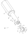
図1は、本実施形態に係る切削工具の斜視図である。図2は、本実施形態に係る切削工具の分解斜視図である。図3は、切削工具の先端における平面図である。図4は、切削インサートを側面視したホルダの軸方向に沿う断面図である。
Hereinafter, an embodiment of the present invention will be described in detail with reference to the drawings.
Fig. 1 is a perspective view of a cutting tool according to the present embodiment. Fig. 2 is an exploded perspective view of the cutting tool according to the present embodiment. Fig. 3 is a plan view of a tip of the cutting tool. Fig. 4 is a cross-sectional view along the axial direction of a holder, showing a cutting insert as viewed from the side.
図1~図4に示すように、本実施形態に係る切削工具100は、切削インサート10と、ホルダ50とを有している。この切削工具100は、ホルダ50の先端に切削インサート10が装着されており、回転する被加工物に対してホルダ50の先端の切削インサート10によって内径部分を切削する内径切削用の旋削工具である。
As shown in Figures 1 to 4, the
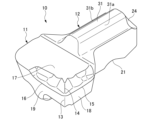
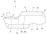
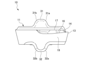
図5は、切削インサートの斜視図である。図6は、切削インサートの下方から視た斜視図である。図7は、切削インサートの平面図である。図8は、切削インサートの側面図である。図9は、切削インサートの正面図である。図10は、切削インサートの裏面図である。 Figure 5 is a perspective view of the cutting insert. Figure 6 is a perspective view of the cutting insert as viewed from below. Figure 7 is a plan view of the cutting insert. Figure 8 is a side view of the cutting insert. Figure 9 is a front view of the cutting insert. Figure 10 is a back view of the cutting insert.
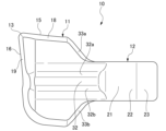
図5~図10に示すように、切削インサート10は、切削部11と、嵌合部12とを有している。嵌合部12は、切削部11の後部に一体に成形されており、切削部11から後方へ向かって延在されている。切削部11は、嵌合部12の両側部から張り出すように形成されている。
As shown in Figures 5 to 10, the cutting
切削インサート10は、例えば、超硬合金、サーメット、セラミックス、超高圧焼結体あるいはダイヤモンドなどの種々の材質から形成されている。
The cutting
切削部11の前部には、上方側における一方側の角部に切れ刃13を有している。また、切削部11は、切れ刃13の上部にブレーカ14を有している。この切れ刃13は、横切れ刃15と、前切れ刃16とを有している。切削部11は、上面がすくい面17とされ、一側面が横逃げ面18とされ、前面が前逃げ面19とされている。横切れ刃15は、すくい面17と横逃げ面18との間に形成され、前切れ刃16は、すくい面17と前逃げ面19との間に形成されている。
The front part of the cutting
このように、切削部11は、側方に設けられた横切れ刃15と、前方に設けられた前切れ刃16とを有しており、横切れ刃15と前切れ刃16とのなす角θ1は、25°以上80°以下とされている(図7参照)。
Thus, the cutting
嵌合部12は、その下部に、係止部21を有している。係止部21は、側面視で凹状に形成されている。この係止部21は、その内面における後方側の傾斜面が被係止面22とされている。また、嵌合部12は、その下部における係止部21よりも後方側に、後端へ向かって次第に上方へ傾斜する摺動面23を有している。また、嵌合部12は、後端における上部に、テーパ面24を有している。このテーパ面24は、嵌合部12の後端から前方へ向かって次第に上方へ傾斜されている。
The
切削インサート10は、上部及び下部に、前後方向に延在する上部突条部31及び下部突条部32を有している。上部突条部31は、切削インサート10の嵌合部12に形成され、下部突条部32は、切削インサート10の切削部11から嵌合部12の一部にわたって形成されている。
The cutting
上部突条部31には、断面視における両角部に、上部当接面(当接面)31a,31bが延在方向に沿って形成されている。同様に、下部突条部32には、断面視における両角部に、下部当接面(当接面)32a,32bが延在方向に沿って形成されている。
The
また、切削インサート10は、切削部11における嵌合部12側の後面が、それぞれ側部当接面(当接面)33a,33bとされている。
In addition, the rear surface of the cutting
図11は、ホルダの斜視図である。図12は、ホルダのインサート取付部の斜視図である。図13は、ホルダのインサート取付部の下方から視た斜視図である。図14は、インサート取付部に設けられたストッパ部を下方から視た斜視図である。図15は、ホルダのインサート取付部の平面図である。図16は、図15におけるA-A断面図である。 Figure 11 is a perspective view of the holder. Figure 12 is a perspective view of the insert mounting portion of the holder. Figure 13 is a perspective view of the insert mounting portion of the holder as viewed from below. Figure 14 is a perspective view of the stopper portion provided on the insert mounting portion as viewed from below. Figure 15 is a plan view of the insert mounting portion of the holder. Figure 16 is a cross-sectional view taken along line A-A in Figure 15.
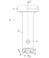
図11~図16に示すように、ホルダ50は、円柱状に形成されており、先端に切削インサート10が装着される。ホルダ50は、シャンク部51と、インサート取付部52とを有している。インサート取付部52は、シャンク部51よりも小径に形成されている。
As shown in Figures 11 to 16, the
このホルダ50は、鋼材等の金属材料から形成されている。このホルダ50の材質としては、例えば、弾性を有しかつ塑性変形しづらい合金工具鋼鋼材(SKS5)、ダイス鋼(SKD61)、マルエージング鋼などが好ましい。
The
ホルダ50は、例えば、金属粉末を用いて造形物を3次元造形する金属粉末焼結3Dプリンターによって造形される。金属粉末焼結3Dプリンターによる造形方法としては、例えば、粉末床溶融結合(Powder bed fusion)、電子ビームを用いて粉末を溶融させる電子ビーム溶融法(EBM:Electron Beam Melting)、あるいはレーザ光を用いて粉末を溶融させるレーザ溶融法(SLM:Selective Laser Melting)などが挙げられる。
The
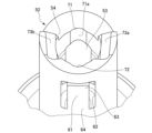
ホルダ50のインサート取付部52は、その先端に、インサートポケット53を有している。このインサートポケット53は、インサート取付部52の端面に形成された穴部からなり、このインサートポケット53に、切削インサート10が嵌合部12側から嵌合される。また、インサート取付部52の端部には、その上部に切欠き部54が形成されており、インサートポケット53の一部が露出されている。
The
インサート取付部52は、その下部に、ストッパ部61を有している。インサート取付部52の下部には、開口部62が設けられており、ストッパ部61は、この開口部62に配置されている。
The
ストッパ部61は、インサートポケット53の長手方向に延在している。このストッパ部61は、先端側が自由端63とされ、後端側がホルダ50に連設された基端64とされた片支持梁状に形成されている。このストッパ部61は、その自由端63に、インサートポケット53側へ突出する凸部65を有している。この凸部65は、インサートポケット53に嵌合される切削インサート10の嵌合部12に形成された係止部21に係合可能とされている。この凸部65は、その外面における後方側の傾斜面が係止面66とされている。
The
インサート取付部52には、ストッパ部61におけるインサートポケット53側に、インサートポケット53への切削インサート10の嵌合部12の嵌め込み方向に沿うスリット67が形成されている。これにより、ストッパ部61が容易に弾性変形可能とされている。
The
インサート取付部52は、上部凹状部71及び下部凹状部72を有している。上部凹状部71は、インサートポケット53の内面における上部に形成され、下部凹状部72は、インサートポケット53の内面における下部に形成されている。これらの上部凹状部71及び下部凹状部72は、それぞれ断面視で円弧状に形成されており、それぞれの内面が上部拘束面(拘束面)71a及び下部拘束面(拘束面)72aとされている。これらの上部凹状部71及び下部凹状部72には、インサート取付部52に装着される切削インサート10の上部突条部31及び下部突条部32が入り込む。これにより、これらの上部凹状部71の上部拘束面71a及び下部凹状部72の下部拘束面72aが、切削インサート10の上部突条部31及び下部突条部32に形成された上部当接面31a,31b及び下部当接面32a,32bに当接する。
The
さらに、インサート取付部52は、その端面における両側部に、側部拘束面(拘束面)73a,73bを有している。これらの側部拘束面73a,73bは、インサート取付部52に装着される切削インサート10の側部当接面33a,33bに当接する。
The
また、インサート取付部52は、キーホール75を有している。このキーホール75は、インサート取付部52の上部に形成されており、インサートポケット53における切削インサート10の嵌合方向前方側に連通されている。
The
次に、切削インサート10のホルダ50への装着について説明する。
切削インサート10をホルダ50に装着するには、ホルダ50のインサート取付部52に対して、その先端側から切削インサート10を近付ける。このとき、切削インサート10の嵌合部12をホルダ50へ向けるとともに、切削インサート10の上下位置をホルダ50に合わせる(図2参照)。
Next, the mounting of the cutting
To mount the cutting
そして、切削インサート10の嵌合部12を、ホルダ50のインサート取付部52に形成されたインサートポケット53へ挿し込む。このようにすると、切削インサート10の上部突条部31及び下部突条部32が、ホルダ50のインサート取付部52に形成された上部凹状部71及び下部凹状部72に係合する。
Then, the
この状態で、切削インサート10をホルダ50へ向かって指で押し込む。すると、切削インサート10は、上部突条部31及び下部突条部32が上部凹状部71及び下部凹状部72によってガイドされながらインサートポケット53の奥側へ移動する。
In this state, the cutting
また、インサートポケット53内へ切削インサート10が押し込まれると、切削インサート10の摺動面23がホルダ50のストッパ部61の凸部65に接触して互いに摺動する。この状態から、切削インサート10がさらに押し込まれると、切削インサート10の嵌合部12によってストッパ部61が外方(図4の紙面下方向)へ押し出されて弾性変形する。
When the cutting
その後、切削インサート10の係止部21に凸部65が入り込み、係止部21の被係止面22に凸部65の係止面66が接触する。すると、弾性変形しているストッパ部61が復元することにより、係止部21の被係止面22に凸部65の係止面66が摺動し、復元するストッパ部61の弾性力が、互いに摺動する係止部21の被係止面22と凸部65の係止面66を介して切削インサート10に伝達され、この切削インサート10がインサートポケット53の奥側へ引き込まれて装着される。
Then, the
このように、インサートポケット53に切削インサート10の嵌合部12を嵌合させることにより、切削インサート10の凹状の係止部21に弾性変形したストッパ部61の凸部65が係合する構造のクランプ機構を備えているので、切削インサート10をインサートポケット53へ容易に引き込むことができる。
In this way, by fitting the
また、切削インサート10の凹状の係止部21にストッパ部61の凸部65が係合する際に、弾性変形していたストッパ部61が復元するので、このストッパ部61が復元する際の感覚(いわゆるクリック感)によって、切削インサート10の装着の完了を容易に把握できる。
In addition, when the
ホルダ50に切削インサート10が装着された切削工具100では、ホルダ50に装着された切削インサート10の係止部21の被係止面22がホルダ50のストッパ部61の凸部65の係止面66によって係止され、ホルダ50への切削インサート10の装着状態が維持される(図4参照)。
In a
また、この装着状態において、切削インサート10の上部当接面31a,31b及び下部当接面32a,32bがホルダ50の上部拘束面71a及び下部拘束面72aに当接され、さらに、切削インサート10の側部当接面33a,33bがホルダ50の側部拘束面73a,73bに当接される。これにより、ホルダ50のインサートポケット53に嵌合されて装着された切削インサート10は、高い保持力でホルダ50にがたつきなく保持される。
In addition, in this mounted state, the
ホルダ50に切削インサート10が装着された切削工具100は、被加工物Wを切削する際に、被加工物Wに対する前切れ刃16の切込み角θ2が60°以上145°以下となる(図3参照)。つまり、切削工具100は、横切れ刃15と前切れ刃16とのなす角θ1が25°以上80°以下であり、また、前切れ刃16における切込み角θ2が60°以上145°以下となる切れ刃13によって、ISOで規格化されている菱形インサートが装着された切削工具と同様の切削加工を被加工物Wに対して行うことができる。
When cutting the workpiece W, the
ここで、被加工物Wを切削する際に、切削インサート10は、被加工物Wから、軸方向に対して平面方向へ直交する軸回りに回転する反力を受ける。具体的には、前切れ刃16における被加工物Wからの切削抵抗によって反力F1を受け、横切れ刃15における被加工物Wからの切削抵抗によって反力F2を受ける(図3参照)。
When cutting the workpiece W, the cutting
切削工具100では、切削インサート10が反力F1,F2を受けた際に、切削インサート10の側部当接面33aに当接するホルダ50の側部拘束面73aが反力F1を受け止め、切削インサート10の側部当接面33bに当接するホルダ50の側部拘束面73bが反力F2を受け止める。したがって、被加工物Wの加工時における切削インサート10の変動を抑えることができ、切削加工を良好に行うことができる。
In the
次に、切削インサート10のホルダ50からの取り外しについて説明する。
切削インサート10をホルダ50から取り外すには、ホルダ50に形成されたキーホール75にピンPを押し込む(図4参照)。すると、このピンPの先端によって切削インサート10の嵌合部12に形成されたテーパ面24が押圧される。すると、ストッパ部61が外方(図4の紙面下方向)に押し出されて弾性変形するとともに、インサートポケット53に嵌合されて装着された切削インサート10が嵌合方向と反対方向へ押し出され、ストッパ部61による切削インサート10の係止が解除される。これにより、ネジによって切削インサート10を装着する構造と比べ、ホルダ50のインサートポケット53から切削インサート10を容易に取り外すことができる。
Next, removal of the cutting
To remove the cutting
なお、ピンPを押し込むキーホール75は、切削インサート10のインサートポケット53への嵌合方向に沿う長孔でもよい。この場合、長孔からなるキーホール75に挿し込んだピンPの後端をホルダ50の後方へ倒すことにより、キーホール75との接触箇所を支点としてピンPを揺動させ、ピンPの先端によって切削インサート10をインサートポケット53から容易に押し出して取り外すことができる。
The
以上、説明したように、本実施形態によれば、インサートポケット53に嵌合される切削インサート10をストッパ部61によって弾性的に係止して装着させる構造のクランプ機構を備えているので、ネジによって切削インサートをホルダへ装着する構造と比べ、切削インサート10をホルダ50へ容易にかつ安定して装着させることができる。これにより、切削インサート10のホルダ50への装着作業性を向上でき、また、ネジの落下や紛失などの不具合を解消できる。しかも、ネジ山を不要にできるので、ホルダ50を小径にでき、小物部品の加工が可能である。
As described above, according to this embodiment, the cutting
なお、本発明は、内径切削用に限らず、回転する被加工物に対して角形のホルダの先端に装着した切削インサートによって外径部分を切削する外径切削用の旋削工具にも適用可能である。また、切削インサートの切れ刃を内径溝入れ刃型や端面溝入れ刃型に置き換え、内径溝入れ加工や端面溝入れ加工を行う場合にも対応可能である。 The present invention is not limited to internal diameter cutting, but can also be applied to external diameter cutting turning tools that use a cutting insert attached to the tip of a square holder to cut the outer diameter of a rotating workpiece. It can also be used to replace the cutting edge of the cutting insert with an internal diameter grooving blade type or an end face grooving blade type to perform internal diameter grooving or end face grooving.
10 切削インサート
11 切削部
12 嵌合部
13 切れ刃
15 横切れ刃
16 前切れ刃
21 係止部
31a,31b 上部当接面(当接面)
32a,32b 下部当接面(当接面)
33a,33b 側部当接面(当接面)
50 ホルダ
53 インサートポケット
61 ストッパ部
65 凸部
67 スリット
71a 上部拘束面(拘束面)
72a 下部拘束面(拘束面)
73a,73b 側部拘束面(拘束面)
75 キーホール
100 切削工具
W 被加工物
θ1 なす角
θ2 切込み角
10
32a, 32b Lower contact surface (contact surface)
33a, 33b Side abutment surfaces (abutment surfaces)
50
72a Lower restraint surface (restraint surface)
73a, 73b Side restraint surfaces (restraint surfaces)
75
Claims (15)
切れ刃を有する切削部と、
前記ホルダに形成されたインサートポケットに嵌合される嵌合部と、
を有し、
前記嵌合部には、前記ホルダの一部に係止される凹状の係止部を有する、
切削インサート。 A cutting insert attached to a tip of a holder,
A cutting portion having a cutting edge;
a fitting portion that is fitted into an insert pocket formed in the holder;
having
The fitting portion has a recessed locking portion that is locked to a part of the holder.
Cutting insert.
請求項1に記載の切削インサート。 The insert pocket has an abutment surface that is abutted against the inner surface of the insert pocket and is restrained against the holder.
The cutting insert according to claim 1 .
側方に設けられた横切れ刃と、
前方に設けられた前切れ刃と、
を有し、
前記横切れ刃と前記前切れ刃とのなす角が25°以上80°以下である、
請求項1に記載の切削インサート。 The cutting portion is
A side cutting edge provided on the side;
A front cutting edge provided at the front,
having
The angle between the side cutting edge and the front cutting edge is 25° or more and 80° or less.
The cutting insert according to claim 1 .
前記切削インサートが嵌合されるインサートポケットと、
前記インサートポケットに嵌合される前記切削インサートを弾性的に係止するストッパ部と、
を有する、
ホルダ。 A holder having a cutting insert attached to a tip thereof,
an insert pocket into which the cutting insert is fitted;
a stopper portion that elastically engages the cutting insert fitted into the insert pocket;
having
Holder.
請求項4に記載のホルダ。 A slit is formed on the insert pocket side of the stopper portion along a fitting direction of the cutting insert into the insert pocket.
The holder according to claim 4.
請求項4に記載のホルダ。 The stopper portion has a protrusion that engages with a concave locking portion formed on the cutting insert that is fitted into the insert pocket.
The holder according to claim 4.
請求項4に記載のホルダ。 The insert pocket has a restraining surface that abuts against an outer surface of the cutting insert to hold the cutting insert.
The holder according to claim 4.
請求項4に記載のホルダ。 A keyhole is formed in the insert pocket so as to communicate with a front side of the cutting insert in a fitting direction.
The holder according to claim 4.
ホルダと、
前記ホルダの先端に装着される切削インサートと、
を備え、
前記ホルダは、
前記切削インサートが嵌合されるインサートポケットと、
前記インサートポケットに嵌合される前記切削インサートを弾性的に係止するストッパ部と、
を有し、
前記切削インサートは、
切れ刃を有する切削部と、
前記インサートポケットに嵌合される嵌合部と、
前記嵌合部に形成され、前記ホルダの前記ストッパ部に係止される係止部と、
を有する、
切削工具。 A cutting tool used for cutting a workpiece,
A holder and
A cutting insert attached to a tip of the holder;
Equipped with
The holder includes:
an insert pocket into which the cutting insert is fitted;
a stopper portion that elastically engages the cutting insert fitted into the insert pocket;
having
The cutting insert comprises:
A cutting portion having a cutting edge;
A fitting portion that is fitted into the insert pocket;
a locking portion formed on the fitting portion and adapted to be locked to the stopper portion of the holder;
having
Cutting tools.
請求項9に記載の切削工具。 A slit is formed on the insert pocket side of the stopper portion along a fitting direction of the cutting insert into the insert pocket.
10. The cutting tool of claim 9.
請求項9に記載の切削工具。 The stopper portion has a protrusion that engages with the recessed locking portion formed on the cutting insert that is fitted into the insert pocket.
10. The cutting tool of claim 9.
前記切削インサートは、前記インサートポケットに前記嵌合部を嵌合することにより、前記拘束面が当接されて前記ホルダに保持される当接面を有する、
請求項9に記載の切削工具。 the insert pocket of the holder has a restraining surface;
The cutting insert has an abutment surface that is abutted against the restraint surface and held by the holder by fitting the fitting portion into the insert pocket.
10. The cutting tool of claim 9.
請求項9に記載の切削工具。 The holder has a keyhole communicating with a front side of the insert pocket in a fitting direction of the cutting insert.
10. The cutting tool of claim 9.
側方に設けられた横切れ刃と、
前方に設けられた前切れ刃と、
を有し、
前記横切れ刃と前記前切れ刃とのなす角が25°以上80°以下である、
請求項9に記載の切削工具。 The cutting portion is
A side cutting edge provided on the side;
A front cutting edge provided at the front,
having
The angle between the side cutting edge and the front cutting edge is 25° or more and 80° or less.
10. The cutting tool of claim 9.
請求項14に記載の切削工具。 The leading cutting edge has a cutting angle with respect to the workpiece during cutting of 60° or more and 145° or less.
15. The cutting tool of claim 14.
Priority Applications (3)
| Application Number | Priority Date | Filing Date | Title |
|---|---|---|---|
| JP2023031326A JP2024123701A (en) | 2023-03-01 | 2023-03-01 | Cutting insert, holder and cutting tool |
| EP24158717.9A EP4424444A1 (en) | 2023-03-01 | 2024-02-20 | Cutting insert, holder, and cutting tool |
| US18/587,866 US20240293872A1 (en) | 2023-03-01 | 2024-02-26 | Cutting insert, holder, and cutting tool |
Applications Claiming Priority (1)
| Application Number | Priority Date | Filing Date | Title |
|---|---|---|---|
| JP2023031326A JP2024123701A (en) | 2023-03-01 | 2023-03-01 | Cutting insert, holder and cutting tool |
Publications (1)
| Publication Number | Publication Date |
|---|---|
| JP2024123701A true JP2024123701A (en) | 2024-09-12 |
Family
ID=90014286
Family Applications (1)
| Application Number | Title | Priority Date | Filing Date |
|---|---|---|---|
| JP2023031326A Pending JP2024123701A (en) | 2023-03-01 | 2023-03-01 | Cutting insert, holder and cutting tool |
Country Status (3)
| Country | Link |
|---|---|
| US (1) | US20240293872A1 (en) |
| EP (1) | EP4424444A1 (en) |
| JP (1) | JP2024123701A (en) |
Citations (4)
| Publication number | Priority date | Publication date | Assignee | Title |
|---|---|---|---|---|
| JP3056024U (en) * | 1997-06-18 | 1999-02-02 | イスカーリミテッド | Cutting tool assembly |
| KR20040053606A (en) * | 2002-12-17 | 2004-06-24 | 한국야금 주식회사 | An holder having improved clamping force and insert using thereof |
| JP2012501864A (en) * | 2008-09-11 | 2012-01-26 | イスカーリミテッド | Cutting tool and cutting tip therefor |
| JP2014526390A (en) * | 2011-09-19 | 2014-10-06 | バルター アクチェンゲゼルシャフト | Insert and clamping holder with 4-point contact |
Family Cites Families (16)
| Publication number | Priority date | Publication date | Assignee | Title |
|---|---|---|---|---|
| AT381262B (en) * | 1982-05-18 | 1986-09-25 | Ver Edelstahlwerke Ag | Parting and grooving tool |
| SE505488C2 (en) * | 1992-04-28 | 1997-09-08 | Sandvik Ab | Cut-off tools or similar operations |
| IL127192A (en) * | 1998-11-22 | 2008-06-05 | Gideon Barazani | Resilient clamping mechanism for inserts |
| JP4892865B2 (en) | 2005-05-12 | 2012-03-07 | 株式会社タンガロイ | Boring tool |
| KR20100014870A (en) * | 2007-04-20 | 2010-02-11 | 미쓰비시 마테리알 가부시키가이샤 | Cutting insert, and cutting method |
| AT505360B1 (en) * | 2007-05-24 | 2011-09-15 | Boehlerit Gmbh & Co Kg | CUTTING TOOL WITH DETACHABLE CUTTING PLATES |
| WO2009028679A1 (en) * | 2007-08-30 | 2009-03-05 | Kyocera Corporation | Cutting tool and cutting method |
| IL198053A (en) | 2009-04-07 | 2012-03-29 | Iscar Ltd | Cutting tool and cutting insert therefor |
| US9120239B2 (en) | 2013-02-21 | 2015-09-01 | Iscar, Ltd. | Cutting tool and cutting insert having insert key recesses for extracting and mounting therein |
| US10213850B2 (en) * | 2013-04-25 | 2019-02-26 | Kennametal Inc. | Cutting insert, a cutting insert holder, a system including the cutting insert and cutting insert holder, and a method of manufacturing thereof |
| SE537176C2 (en) * | 2013-06-28 | 2015-02-24 | Sandvik Intellectual Property | Tools for chip removal machining, as well as cutting holding blades and key for this |
| JP6677870B2 (en) * | 2016-02-26 | 2020-04-08 | 三菱マテリアル株式会社 | Indexable grooving tool with clamp work tool and clamp work tool |
| DE202016105061U1 (en) * | 2016-09-13 | 2017-12-14 | Baum Gmbh Zerspanungstechnik & Werkzeugbau | Tool, in particular for cutting workpiece machining |
| JP2020157416A (en) | 2019-03-26 | 2020-10-01 | 三菱マテリアル株式会社 | Replaceable cutting tools, cutting inserts, and tool bodies |
| JP2020163524A (en) | 2019-03-29 | 2020-10-08 | 三菱マテリアル株式会社 | Replaceable cutting tools, cutting inserts, and tool bodies |
| US11766724B1 (en) * | 2022-03-16 | 2023-09-26 | Iscar, Ltd. | Cutting tool and tool holder having separate rear abutment and wedged rear stopper surfaces |
-
2023
- 2023-03-01 JP JP2023031326A patent/JP2024123701A/en active Pending
-
2024
- 2024-02-20 EP EP24158717.9A patent/EP4424444A1/en active Pending
- 2024-02-26 US US18/587,866 patent/US20240293872A1/en active Pending
Patent Citations (4)
| Publication number | Priority date | Publication date | Assignee | Title |
|---|---|---|---|---|
| JP3056024U (en) * | 1997-06-18 | 1999-02-02 | イスカーリミテッド | Cutting tool assembly |
| KR20040053606A (en) * | 2002-12-17 | 2004-06-24 | 한국야금 주식회사 | An holder having improved clamping force and insert using thereof |
| JP2012501864A (en) * | 2008-09-11 | 2012-01-26 | イスカーリミテッド | Cutting tool and cutting tip therefor |
| JP2014526390A (en) * | 2011-09-19 | 2014-10-06 | バルター アクチェンゲゼルシャフト | Insert and clamping holder with 4-point contact |
Also Published As
| Publication number | Publication date |
|---|---|
| US20240293872A1 (en) | 2024-09-05 |
| EP4424444A1 (en) | 2024-09-04 |
Similar Documents
| Publication | Publication Date | Title |
|---|---|---|
| US7780380B2 (en) | Insert-indexable tool | |
| CN100418680C (en) | Cutting heads for rotary cutting tools | |
| EP2498936B1 (en) | Cutting tool | |
| KR101536383B1 (en) | Cutting tool and cutting insert therefor | |
| CN102378658B (en) | Cutting tool assembly and tool holder therefor | |
| EP3600734B1 (en) | Blade-shaped cutting insert and cutting tool therefor | |
| JP2012518548A (en) | Cutting tool with adjusting mechanism | |
| JP2016182671A (en) | Tool block, clamp member, and cutting tool | |
| JP7568939B2 (en) | Interchangeable head cutting tool, cutting head, and tool body | |
| JP7757411B2 (en) | Cutting tool and method for manufacturing machined product | |
| JP2007253299A (en) | Clamp mechanism of cutting insert, cutting insert and insert detachable cutting tool | |
| JP2024123701A (en) | Cutting insert, holder and cutting tool | |
| CN113474110B (en) | Turning tool and method for manufacturing cut product | |
| EP0107481B1 (en) | Quick-change tool | |
| US12544839B2 (en) | Tool assembly configured for Swiss machining | |
| JP2020163524A (en) | Replaceable cutting tools, cutting inserts, and tool bodies | |
| KR100296445B1 (en) | Indexable boring tool for cutting an internal surface of a small size's hole | |
| CN118251284A (en) | Cutting tool and method for producing cut product | |
| JP4814633B2 (en) | Holder, insert and cutting tool | |
| JP2025150903A (en) | Holder, cutting tool, and method for manufacturing machined product | |
| JP7818091B2 (en) | Cutting unit, cutting tool, tool rest, and method for manufacturing machined product | |
| WO2025154369A1 (en) | Cutting tool and method for manufacturing cut workpiece | |
| JP7527489B2 (en) | Holder, cutting tool, and method for manufacturing machined product | |
| US20240316652A1 (en) | Clamp structure of cutting insert and indexable cutting tool | |
| JP2000237904A (en) | Turning tools |
Legal Events
| Date | Code | Title | Description |
|---|---|---|---|
| A621 | Written request for application examination |
Free format text: JAPANESE INTERMEDIATE CODE: A621 Effective date: 20231129 |
|
| A131 | Notification of reasons for refusal |
Free format text: JAPANESE INTERMEDIATE CODE: A131 Effective date: 20241112 |
|
| A521 | Request for written amendment filed |
Free format text: JAPANESE INTERMEDIATE CODE: A523 Effective date: 20241224 |
|
| A02 | Decision of refusal |
Free format text: JAPANESE INTERMEDIATE CODE: A02 Effective date: 20250221 |
|
| A521 | Request for written amendment filed |
Free format text: JAPANESE INTERMEDIATE CODE: A523 Effective date: 20250319 |
|
| A521 | Request for written amendment filed |
Free format text: JAPANESE INTERMEDIATE CODE: A523 Effective date: 20260410 |