JP2024123777A - Wheel bearing device - Google Patents
Wheel bearing device Download PDFInfo
- Publication number
- JP2024123777A JP2024123777A JP2023031447A JP2023031447A JP2024123777A JP 2024123777 A JP2024123777 A JP 2024123777A JP 2023031447 A JP2023031447 A JP 2023031447A JP 2023031447 A JP2023031447 A JP 2023031447A JP 2024123777 A JP2024123777 A JP 2024123777A
- Authority
- JP
- Japan
- Prior art keywords
- wheel
- diameter
- axial end
- lip
- bearing device
- Prior art date
- Legal status (The legal status is an assumption and is not a legal conclusion. Google has not performed a legal analysis and makes no representation as to the accuracy of the status listed.)
- Pending
Links
Images



Classifications
-
- F—MECHANICAL ENGINEERING; LIGHTING; HEATING; WEAPONS; BLASTING
- F16—ENGINEERING ELEMENTS AND UNITS; GENERAL MEASURES FOR PRODUCING AND MAINTAINING EFFECTIVE FUNCTIONING OF MACHINES OR INSTALLATIONS; THERMAL INSULATION IN GENERAL
- F16C—SHAFTS; FLEXIBLE SHAFTS; ELEMENTS OR CRANKSHAFT MECHANISMS; ROTARY BODIES OTHER THAN GEARING ELEMENTS; BEARINGS
- F16C33/00—Parts of bearings; Special methods for making bearings or parts thereof
- F16C33/72—Sealings
- F16C33/76—Sealings of ball or roller bearings
- F16C33/78—Sealings of ball or roller bearings with a diaphragm, disc, or ring, with or without resilient members
- F16C33/7803—Sealings of ball or roller bearings with a diaphragm, disc, or ring, with or without resilient members suited for particular types of rolling bearings
- F16C33/7806—Sealings of ball or roller bearings with a diaphragm, disc, or ring, with or without resilient members suited for particular types of rolling bearings for spherical roller bearings
-
- F—MECHANICAL ENGINEERING; LIGHTING; HEATING; WEAPONS; BLASTING
- F16—ENGINEERING ELEMENTS AND UNITS; GENERAL MEASURES FOR PRODUCING AND MAINTAINING EFFECTIVE FUNCTIONING OF MACHINES OR INSTALLATIONS; THERMAL INSULATION IN GENERAL
- F16C—SHAFTS; FLEXIBLE SHAFTS; ELEMENTS OR CRANKSHAFT MECHANISMS; ROTARY BODIES OTHER THAN GEARING ELEMENTS; BEARINGS
- F16C33/00—Parts of bearings; Special methods for making bearings or parts thereof
- F16C33/72—Sealings
- F16C33/76—Sealings of ball or roller bearings
- F16C33/78—Sealings of ball or roller bearings with a diaphragm, disc, or ring, with or without resilient members
- F16C33/7816—Details of the sealing or parts thereof, e.g. geometry, material
-
- F—MECHANICAL ENGINEERING; LIGHTING; HEATING; WEAPONS; BLASTING
- F16—ENGINEERING ELEMENTS AND UNITS; GENERAL MEASURES FOR PRODUCING AND MAINTAINING EFFECTIVE FUNCTIONING OF MACHINES OR INSTALLATIONS; THERMAL INSULATION IN GENERAL
- F16C—SHAFTS; FLEXIBLE SHAFTS; ELEMENTS OR CRANKSHAFT MECHANISMS; ROTARY BODIES OTHER THAN GEARING ELEMENTS; BEARINGS
- F16C33/00—Parts of bearings; Special methods for making bearings or parts thereof
- F16C33/72—Sealings
- F16C33/76—Sealings of ball or roller bearings
- F16C33/78—Sealings of ball or roller bearings with a diaphragm, disc, or ring, with or without resilient members
- F16C33/7816—Details of the sealing or parts thereof, e.g. geometry, material
- F16C33/782—Details of the sealing or parts thereof, e.g. geometry, material of the sealing region
- F16C33/7823—Details of the sealing or parts thereof, e.g. geometry, material of the sealing region of sealing lips
-
- F—MECHANICAL ENGINEERING; LIGHTING; HEATING; WEAPONS; BLASTING
- F16—ENGINEERING ELEMENTS AND UNITS; GENERAL MEASURES FOR PRODUCING AND MAINTAINING EFFECTIVE FUNCTIONING OF MACHINES OR INSTALLATIONS; THERMAL INSULATION IN GENERAL
- F16C—SHAFTS; FLEXIBLE SHAFTS; ELEMENTS OR CRANKSHAFT MECHANISMS; ROTARY BODIES OTHER THAN GEARING ELEMENTS; BEARINGS
- F16C2233/00—Monitoring condition, e.g. temperature, load, vibration
-
- F—MECHANICAL ENGINEERING; LIGHTING; HEATING; WEAPONS; BLASTING
- F16—ENGINEERING ELEMENTS AND UNITS; GENERAL MEASURES FOR PRODUCING AND MAINTAINING EFFECTIVE FUNCTIONING OF MACHINES OR INSTALLATIONS; THERMAL INSULATION IN GENERAL
- F16C—SHAFTS; FLEXIBLE SHAFTS; ELEMENTS OR CRANKSHAFT MECHANISMS; ROTARY BODIES OTHER THAN GEARING ELEMENTS; BEARINGS
- F16C2326/00—Articles relating to transporting
- F16C2326/01—Parts of vehicles in general
- F16C2326/02—Wheel hubs or castors
Landscapes
- Engineering & Computer Science (AREA)
- General Engineering & Computer Science (AREA)
- Mechanical Engineering (AREA)
- Rolling Contact Bearings (AREA)
- Sealing With Elastic Sealing Lips (AREA)
- Sealing Devices (AREA)
- Sealing Of Bearings (AREA)
Abstract
Description
本発明は車輪用軸受装置に関する。 The present invention relates to a wheel bearing device.
従来、自動車等の懸架装置において車輪を回転自在に支持する車輪用軸受装置が知られている。車輪用軸受装置には、外方部材と内方部材とによって形成された環状空間の開口端を塞ぎ、泥水等の異物の入り込みを防止する密封装置が設けられている。 Conventionally, wheel bearing devices that support the wheels rotatably in the suspension of an automobile or the like are known. The wheel bearing device is provided with a sealing device that closes the open end of the annular space formed by the outer member and the inner member to prevent the intrusion of foreign matter such as muddy water.
例えば、特許文献1に開示される密封装置は、外方部材の内周面に嵌合される嵌合部と、嵌合部から内径側へ延びる内側部とを有する芯金と、芯金の内側部から車輪取り付けフランジ側へ向けて延びるサイドリップと、最も外径側に位置するサイドリップの基端部から外径側へ延びて芯金を覆う覆い部とを有するシール部材とからなっている。 For example, the sealing device disclosed in Patent Document 1 is made up of a core bar having a fitting portion that fits into the inner peripheral surface of the outer member and an inner portion that extends from the fitting portion toward the inner diameter side, a side lip that extends from the inner portion of the core bar toward the wheel mounting flange side, and a cover portion that extends from the base end of the side lip located on the outermost diameter side toward the outer diameter side to cover the core bar.
このような密封装置のシール部材においては、最も外径側に位置するサイドリップの外径よりも覆い部の外径の方が大きくなるように形成されており、例えばサイドリップの外径端は、覆い部の外径端よりも1mm内径側に位置するように設定されている。この場合、覆い部は、平面部よりも外径側に突出するノーズ部を有しており、ノーズ部の外径端が覆い部の外径端となっているため、ノーズ部の外径端からサイドリップの外径端までの径方向の距離が1mmとなるように設定されている。 In the seal member of such a sealing device, the outer diameter of the cover portion is formed to be larger than the outer diameter of the side lip located on the outermost side, and for example, the outer diameter end of the side lip is set to be located 1 mm on the inner diameter side of the outer diameter end of the cover portion. In this case, the cover portion has a nose portion that protrudes outward from the flat portion, and the outer diameter end of the nose portion is the outer diameter end of the cover portion, so that the radial distance from the outer diameter end of the nose portion to the outer diameter end of the side lip is set to be 1 mm.
一方、覆い部は、覆い部の外径端とサイドリップの外径端との間に、軸方向において車輪取り付けフランジ側に面する平面部を有しており、密封装置を外方部材に圧入する際には、シール部材の平面部を圧入治具によって押圧することで、密封装置の外方部材に対する圧入を行っていた。 On the other hand, the cover portion has a flat portion that faces the wheel mounting flange side in the axial direction between the outer diameter end of the cover portion and the outer diameter end of the side lip, and when the sealing device is pressed into the outer member, the flat portion of the seal member is pressed with a pressing jig to press the sealing device into the outer member.
しかし、ノーズ部の外径端からサイドリップの外径端までの距離が1mmに設定されていたため、平面部の外径端からサイドリップの外径端までの距離は1mmよりも小さくなっていた。 However, because the distance from the outer diameter end of the nose portion to the outer diameter end of the side lip was set to 1 mm, the distance from the outer diameter end of the flat portion to the outer diameter end of the side lip was less than 1 mm.
このように、平面部の外径端からサイドリップの外径端までの距離は1mmよりも小さな値に設定されていたため、圧入治具によって押圧される平面部の面積が小さくなって、密封装置の外方部材に対する圧入を、安定して行うことができないおそれがあった。 In this way, the distance from the outer diameter end of the flat portion to the outer diameter end of the side lip was set to a value smaller than 1 mm, so the area of the flat portion pressed by the press-fitting tool was small, and there was a risk that the sealing device could not be stably pressed into the outer member.
本発明は以上の如き状況に鑑みてなされたものであり、圧入治具によって押圧される平面部の面積を確保して、密封装置の外方部材に対する圧入を安定して行うことができる車輪用軸受装置を提供するものである。 The present invention was made in consideration of the above situation, and provides a wheel bearing device that ensures the area of the flat surface that is pressed by the press-fitting tool, and allows the sealing device to be stably pressed into the outer member.
即ち、車輪用軸受装置は、内周に複列の外側軌道面を有する外方部材と、軸方向の一端部に車輪を取り付けるための車輪取り付けフランジを有し、外周に軸方向に延びる小径段部を有するハブ輪、および前記ハブ輪の小径段部に圧入された少なくとも一つの内輪からなり、前記複列の外側軌道面に対向する複列の内側軌道面を有する内方部材と、前記外方部材と前記内方部材との両軌道面間に転動自在に収容された複列の転動体と、前記外方部材と前記内方部材とによって形成された環状空間の軸方向一端側の開口端を塞ぐ密封装置と、を備える車輪用軸受装置であって、前記密封装置は、前記外方部材の軸方向一端部における内周面に嵌合される嵌合部と、前記嵌合部の軸方向一端部から内径側へ延びる内側部とを有する芯金と、前記芯金に一体的に接合され、前記芯金の前記内側部から前記車輪取り付けフランジ側へ向けて延びるサイドリップと、最も外径側に位置する前記サイドリップの基端部から外径側へ延び、軸方向一端側に面する平面部とを有するシール部材と、を備え、前記サイドリップの外径端は、前記平面部の外径端よりも1mm以上内径側に位置する。 That is, the wheel bearing device comprises an outer member having a double-row outer raceway surface on its inner circumference, a hub wheel having a wheel mounting flange for mounting a wheel at one axial end thereof and a small diameter step extending in the axial direction on its outer circumference, and at least one inner ring press-fitted into the small diameter step of the hub wheel, an inner member having a double-row inner raceway surface facing the double-row outer raceway surface, double-row rolling elements accommodated in a rollable manner between the raceway surfaces of the outer member and the inner member, and a sealing device closing an opening end on one axial end side of an annular space formed by the outer member and the inner member. A wheel bearing device comprising: a core having a fitting portion that fits into the inner peripheral surface at one axial end of the outer member, and an inner portion that extends from the axial end of the fitting portion toward the inner diameter side; a side lip that is integrally joined to the core and extends from the inner portion of the core toward the wheel mounting flange; and a seal member that extends from the base end of the side lip located on the outermost diameter side toward the outer diameter side and has a flat portion that faces the axial end side, and the outer diameter end of the side lip is located 1 mm or more toward the inner diameter side of the outer diameter end of the flat portion.
本発明によれば、シール部材における平面部の面積を大きく確保することができ、密封装置の外方部材に対する圧入を安定して行うことができる。 According to the present invention, it is possible to ensure a large area of the flat surface of the sealing member, and the sealing device can be stably pressed into the outer member.
以下に、本発明を実施するための形態を、添付の図面を用いて説明する。 Below, the embodiment of the present invention will be explained with reference to the attached drawings.
[車輪用軸受装置]
図1に示す車輪用軸受装置1は、本発明に係る車輪用軸受装置の一実施形態であり、自動車等の車両の懸架装置において車輪を回転自在に支持するものである。
[Wheel bearing device]
A wheel bearing device 1 shown in FIG. 1 is one embodiment of a wheel bearing device according to the present invention, which rotatably supports a wheel in a suspension system of a vehicle such as an automobile.
以下の説明において、軸方向とは車輪用軸受装置1の回転軸心Xに沿った方向を表す。また、アウター側とは、軸方向の一側であって車体に取り付けた際の車輪用軸受装置1の車輪側を表し、インナー側とは、軸方向の他側であって車体に取り付けた際の車輪用軸受装置1の車体側を表す。 In the following description, the axial direction refers to the direction along the rotation axis X of the wheel bearing device 1. The outer side refers to one side in the axial direction, which is the wheel side of the wheel bearing device 1 when it is attached to the vehicle body, and the inner side refers to the other side in the axial direction, which is the vehicle body side of the wheel bearing device 1 when it is attached to the vehicle body.
車輪用軸受装置1は第3世代と称呼される構成を備えており、外方部材である外輪2と、内方部材であるハブ輪3および内輪4と、転動列である二列のインナー側ボール列5およびアウター側ボール列6と、アウター側シール部材10と、キャップ17とを具備する。
The wheel bearing device 1 has a configuration called the third generation, and includes an
外輪2のインナー側端部には、キャップ17が嵌合可能なインナー側開口部2aが形成されている。外輪2のアウター側端部には、アウター側シール部材10が嵌合可能なアウター側開口部2bが形成されている。
An
外輪2とハブ輪3とによって形成された環状空間Sのアウター側開口端となるアウター側開口部2bにアウター側シール部材10を嵌合するとともに、環状空間Sのインナー側開口端となるインナー側開口部2aにキャップ17を嵌合することで、軸受内部となる環状空間Sを密封している。
The annular space S formed by the
外輪2の内周面には、インナー側の外側軌道面2cと、アウター側の外側軌道面2dとが形成されている。外輪2の外周面には、外輪2を車体側部材に取り付けるための車体取り付けフランジ2eが一体的に形成されている。車体取り付けフランジ2eは、ボルト等の締結部材によって車体側部材に締結される。
The inner peripheral surface of the
ハブ輪3のインナー側端部には、外周面にアウター側端部よりも縮径された小径段部3aが形成されている。ハブ輪3のアウター側端部には、車輪を取り付けるための車輪取り付けフランジ3bが一体的に形成されている。車輪取り付けフランジ3bには、複数のボルト孔3fが形成されている。ボルト孔3fには、ハブ輪3と車輪又はブレーキ部品とを締結するためのハブボルト3iを圧入可能である。
The inner end of the
ハブ輪3の外周面には、外輪2のアウター側の外側軌道面2dに対向するようにアウター側の内側軌道面3cが設けられている。つまり、内方部材のアウター側には、ハブ輪3によって内側軌道面3cが構成されている。
The outer peripheral surface of the
車輪取り付けフランジ3bの基端部におけるインナー側には、アウター側シール部材10が摺接するシールランド部3dが形成されている。内側軌道溝3cは、軸方向においてシールランド部3dのインナー側に隣接して位置している。車輪取り付けフランジ3bは、インナー側に面するフランジ面3eを有している。
A
フランジ面3eはシールランド部3dの外径側に位置している。シールランド部3dは、軸方向においてフランジ面3eよりもインナー側に位置しており、フランジ面3eとシールランド部3dとの間には段差部3gが形成されている。
The
ハブ輪3の小径段部3aには、内輪4が設けられている。内輪4は、圧入およびかしめ加工によりハブ輪3の小径段部3aに固定されている。内輪4は、転動列であるインナー側ボール列5およびアウター側ボール列6に予圧を付与している。内輪4は、インナー側端部にインナー側端面4bを有している。
The
ハブ輪3のインナー側端部には、内輪4のインナー側端面4bにかしめられたかしめ部3hが形成されている。内輪4は、かしめ部3hにより軸方向に固定されている。かしめ部3hは、小径段部3aのインナー側端部を外径側に塑性変形させることにより形成されている。
The inner end of the
内輪4の外周面には、外輪2のインナー側の外側軌道面2cと対向するようにインナー側の内側軌道面4aが設けられている。つまり、内方部材のインナー側には、内輪4によって内側軌道面4aが構成されている。
The outer peripheral surface of the
転動列であるインナー側ボール列5とアウター側ボール列6とは、転動体である複数のボール7が保持器8によって保持されることにより構成されている。インナー側ボール列5は、内輪4の内側軌道面4aと、外輪2のインナー側の外側軌道面2cとの間に転動自在に挟まれている。アウター側ボール列6は、ハブ輪3の内側軌道面3cと、外輪2のアウター側の外側軌道面2dとの間に転動自在に挟まれている。つまり、インナー側ボール列5とアウター側ボール列6とは、外方部材と内方部材との両軌道面間に転動自在に収容されている。
The
車輪用軸受装置1においては、外輪2と、ハブ輪3および内輪4と、インナー側ボール列5と、アウター側ボール列6とによって複列アンギュラ玉軸受が構成されている。なお、車輪用軸受装置1は複列アンギュラ玉軸受に替えて複列円錐ころ軸受を構成していてもよい。
In the wheel bearing device 1, a double-row angular ball bearing is formed by the
内輪4のインナー側端部には、断面L字形に形成された支持環15が嵌合されている。支持環15は、内輪4の外径に圧入される円筒部15aと、この円筒部15aから径方向外方に延びる立板部15bとを備え、立板部15bのインナー側の側面に磁気エンコーダ16が加硫接着によって一体的に接合されている。
A
キャップ17のインナー側における磁気エンコーダ16と対向する位置に回転速度センサを配置して、回転速度センサにより磁気エンコーダ16の変位を検出することで、内輪4の回転速度を検出することが可能である。
A rotational speed sensor is placed in a position facing the
[アウター側シール部材]
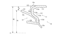
図2、図3に示すように、アウター側シール部材10は、外輪2におけるアウター側端部の内周に嵌合される芯金11と、芯金11に一体的に接合されるシール部材12とを備えている。
[Outer seal member]
As shown in Figures 2 and 3, the
芯金11は、例えば鋼板により構成されており、外輪2のアウター側開口部2bの内周に嵌合される円筒状の嵌合部111と、嵌合部111のインナー側端部から内径側へ延びる内側部112とを有している。
The
内側部112は、嵌合部111のアウター側端部から屈曲されてアウター側かつ内径側へ斜めに延びる外側傾斜部112aと、外側傾斜部112aのアウター側端部から内径側へ延びる外側円環部112bと、外側円環部112bの内径側端部からインナー側かつ内径側へ斜めに延びる内側傾斜部112cと、内側傾斜部112cのインナー側端部から内径側へ延びる内側円環部112dとを有している。
The
シール部材12は、例えば合成ゴム等の弾性部材によって形成されており、芯金11に加硫接着によって接合されている。シール部材12は、ラジアルリップ12aと、第1サイドリップ12bと、第2サイドリップ12cと、平面部12dと、ノーズ部12eとを有している。
The
ラジアルリップ12aは、芯金11の内側円環部112dから、径方向内側かつインナー側へ向けて延びており、シールランド部3dに摺接している。
The
第1サイドリップ12bは、ラジアルリップ12aよりも外径側において、芯金11の内側円環部112dから、車輪取り付けフランジ3b側となるアウター側かつ径方向外側へ向けて延びている。第1サイドリップ12bは、シールランド部3dに摺接している。第1サイドリップ12bは、サイドリップの一例である。
The
第2サイドリップ12cは、第1サイドリップ12bよりも外径側において、芯金11における外側円環部112bと内側傾斜部112cとの境界部付近から、車輪取り付けフランジ3b側となるアウター側かつ径方向外側へ向けて延びている。第2サイドリップ12cは、シールランド部3dに摺接している。第2サイドリップ12cは、サイドリップの一例である。また、第2サイドリップ12cは、最も外径側に位置するサイドリップの一例である。
The
径方向において、回転軸心Xから第2サイドリップ12cの先端部における外径端121までの距離はR1である。
In the radial direction, the distance from the rotation axis X to the
平面部12dは、第2サイドリップ12cの基端部から外径側へ延びており、アウター側に面している。平面部12dのアウター側面は平面状に形成されている。平面部12dのアウター側面は、軸方向と直交する方向に沿った面である。平面部12dは、芯金11の外側円環部112bから外側傾斜部112aにかけて接合されている。
The
平面部12dの外径端122は、第2サイドリップ12cの外径端121よりも外径側に位置している。径方向において、回転軸心Xから平面部12dの外径端122までの距離はR2である。
The outer diameter end 122 of the
第2サイドリップ12cにおける外径端121の距離R1と、平面部12dにおける外径端122の距離R2との距離差はDであり、距離差Dは1mm以上に設定されている。つまり、第2サイドリップ12cの外径端121は、平面部12dの外径端122よりも1mm以上内径側に位置している。
The distance difference between the distance R1 of the outer diameter end 121 of the
ノーズ部12eは、芯金11の外側傾斜部112aに接合されており、平面部12dよりもインナー側に位置し、芯金11の嵌合部111よりも外径側に突出している。ノーズ部12eの外径端は、平面部12dの外径端122よりも外径側に位置している。
The
ノーズ部12eは、芯金11の嵌合部111が外輪2におけるアウター側開口部2bの内周面に嵌合された状態では、アウター側開口部2bの内周面によって内径側に押圧されて、弾性変形している。
When the
内径側に押圧されて弾性変形したノーズ部12eは、弾性変形していない状態に比べてアウター側へ膨出するが、平面部12dよりもアウター側には突出していない。つまり、内径側に押圧されて弾性変形したノーズ部12eのアウター側端は、軸方向において平面部12dのアウター側面と同じ位置、または平面部12dのアウター側面よりもインナー側に位置している。
The
[外輪]
図2、図4に示すように、外輪2のアウター側端面2eは、軸方向においてシールランド部3dの外径側端よりもアウター側に延びており、外輪2のアウター側端面2eの内径側には、ハブ輪3の段差部3gと対向する退避部2fが形成されている。
[Outer ring]
As shown in Figures 2 and 4, the
退避部2fは、段差部3g側に対して凹となる曲面形状に形成されており、外輪2のアウター側端面2eをシールランド部3dの外径側端よりもアウター側に延ばしたときに、外輪2とハブ輪3の段差部3gとが干渉することを抑制している。
The
外輪2は、アウター側開口部2bのアウター側端部に、アウター側へ向かうに従って拡径するテーパ面2gを有している。退避部2fは、テーパ面2gよりもアウター側に位置しており、テーパ面2gと退避部2fとの間にはR面取り部2hが形成されている。
The
R面取り部2hは、テーパ面2gのアウター側端部に位置しており、ハブ輪3のシールランド部3dと対向している。R面取り部2hは、テーパ面2gと退避部2fとの接続部をR面取りすることにより形成され、シールランド部3dに対して凸となる曲面形状を有している。R面取り部2hは、曲率半径が0.5mm以上の曲面形状を有している。R面取り部2hにおいては、外輪2の内周面はアウター側へいくに従って拡径している。
The R-chamfered
[アウター側シール部材の外輪への圧入]
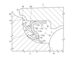
図5に示すように、アウター側シール部材10を外輪2のアウター側開口部2bに嵌合するときには、アウター側シール部材10を圧入治具Pによってインナー側に押圧して、アウター側開口部2bに圧入することにより、アウター側シール部材10をアウター側開口部2bに嵌合する。圧入治具Pは、例えば軸方向に沿って延びる円環状部材により形成されている。
[Press-fitting the outer seal member into the outer ring]
5, when fitting the
この場合、圧入治具Pを、シール部材12における平面部12dの第2サイドリップ12cよりも外径側の部分に当接させて、アウター側シール部材10を圧入治具Pによって圧入する。これにより、圧入治具Pが第2サイドリップ12cに干渉することなく、アウター側シール部材10をアウター側開口部2bに圧入することができる。
In this case, the press-fitting jig P is brought into contact with the portion of the
また、第2サイドリップ12cの外径端121は、平面部12dの外径端122よりも1mm以上内径側に位置しているため、平面部12dにおける圧入治具Pを当接させる部分の面積を大きく確保することができ、アウター側シール部材10の外輪2に対する圧入を安定して行うことが可能である。
In addition, the outer diameter end 121 of the
また、アウター側シール部材10をアウター側開口部2bに圧入する際には、芯金11の嵌合部111よりも外径側に突出するノーズ部12eは、アウター側からインナー側へ移動して、R面取り部2h、テーパ面2g、およびアウター側開口部2bの順に接触し、徐々に圧縮される。従って、ノーズ部12eが急激に弾性変形することが抑制され、ノーズ部12eにゴム切れ等の損傷が生じることを防止できる。
When the
特に、R面取り部2hは、曲率半径が0.5mm以上の曲面形状を有しているため、ノーズ部12eがR面取り部2hに接触して弾性変形した際には、弾性変形してアウター側に膨出したノーズ部12eは外径側へ逃げることが許容され、急激な弾性変形が抑制されるため、ゴム切れ等の損傷が生じにくくなっている。
In particular, the R-chamfered
また、R面取り部2hのインナー側にはテーパ面2gが位置しているため、R面取り部2hを通過したノーズ部12eは、インナー側へ移動する際に徐々に内径側に圧縮されるため、急激な弾性変形が抑制されて、ゴム切れ等の損傷が生じにくくなっている。
In addition, because the tapered
さらに、アウター側開口部2bに圧入されて弾性変形したノーズ部12eは、平面部12dよりもアウター側には突出していないため、圧入時に平面部12dを押圧する圧入治具P等と干渉することがなく、ノーズ部12eにゴム切れ等の損傷が生じることを抑制可能となっている。
Furthermore, the
以上、本発明の実施の形態について説明を行ったが、本発明はこうした実施の形態に何等限定されるものではなく、あくまで例示であって、本発明の要旨を逸脱しない範囲内において、さらに種々なる形態で実施し得ることは勿論のことであり、本発明の範囲は、特許請求の範囲の記載によって示され、さらに特許請求の範囲に記載の均等の意味、および範囲内のすべての変更を含む。 Although the embodiments of the present invention have been described above, the present invention is in no way limited to these embodiments, which are merely examples, and it goes without saying that the present invention can be embodied in various other forms without departing from the spirit of the present invention. The scope of the present invention is indicated by the claims, and further includes the equivalent meanings set forth in the claims, and all modifications within the scope of the claims.
1 車輪用軸受装置
2 外輪
2a インナー側開口部
2b アウター側開口部
2c (インナー側の)外側軌道面
2d (アウター側の)外側軌道面
2f テーパ面
2h R面取り部
3 ハブ輪
3b 車輪取り付けフランジ
3c 内側軌道面
4 内輪
4a 内側軌道面
5 インナー側ボール列
6 アウター側ボール列
10 アウター側シール部材
11 芯金
12 シール部材
12b 第1サイドリップ
12c 第2サイドリップ
12d 平面部
12e ノーズ部
111 嵌合部
112 内側部
D (第2サイドリップの外径端と平面部外径端との)距離差
REFERENCE SIGNS LIST 1
Claims (3)
軸方向の一端部に車輪を取り付けるための車輪取り付けフランジを有し、外周に軸方向に延びる小径段部を有するハブ輪、および前記ハブ輪の小径段部に圧入された少なくとも一つの内輪からなり、前記複列の外側軌道面に対向する複列の内側軌道面を有する内方部材と、
前記外方部材と前記内方部材との両軌道面間に転動自在に収容された複列の転動体と、
前記外方部材と前記内方部材とによって形成された環状空間の軸方向一端側の開口端を塞ぐ密封装置と、を備える車輪用軸受装置であって、
前記密封装置は、
前記外方部材の軸方向一端部における内周面に篏合される嵌合部と、前記嵌合部の軸方向一端部から内径側へ延びる内側部とを有する芯金と、
前記芯金に一体的に接合され、前記芯金の前記内側部から前記車輪取り付けフランジ側へ向けて延びるサイドリップと、最も外径側に位置する前記サイドリップの基端部から外径側へ延び、軸方向一端側に面する平面部とを有するシール部材と、を備え、
前記サイドリップの外径端は、前記平面部の外径端よりも1mm以上内径側に位置する車輪用軸受装置。 an outer member having a double row outer raceway surface on an inner periphery thereof;
an inner member including a hub wheel having a wheel mounting flange at one axial end thereof for mounting a wheel, and a small diameter stepped portion extending in the axial direction on an outer periphery thereof, and at least one inner ring press-fitted into the small diameter stepped portion of the hub wheel, the inner member having a double row inner raceway surface facing the double row outer raceway surfaces;
a double row of rolling elements rollably accommodated between the raceway surfaces of the outer member and the inner member;
a sealing device that closes an open end on one axial end side of an annular space formed by the outer member and the inner member,
The sealing device includes:
a core bar having a fitting portion that is fitted to an inner peripheral surface at one axial end of the outer member and an inner portion that extends from the one axial end of the fitting portion toward an inner diameter side;
a seal member having a side lip that is integrally joined to the core metal and extends from the inner side of the core metal toward the wheel mounting flange side, and a flat portion that extends from a base end of the side lip that is located on the outermost diameter side toward the outer diameter side and faces one axial end side,
A wheel bearing device in which an outer diameter end of the side lip is located 1 mm or more on the inner diameter side of the outer diameter end of the flat portion.
前記テーパ面の軸方向一端部は、周方向から見て曲率半径が0.5mm以上の曲面形状を有する請求項1に記載の車輪用軸受装置。 the outer member has an inner circumferential surface at one axial end portion into which the fitting portion of the core metal is fitted, the inner circumferential surface having a tapered surface that increases in diameter toward the one axial end portion,
2. The wheel bearing device according to claim 1, wherein one axial end of the tapered surface has a curved shape with a radius of curvature of 0.5 mm or more when viewed in the circumferential direction.
前記ノーズ部は、前記嵌合部が前記外方部材の前記内周面に嵌合された状態において、前記内周面に押圧されて弾性変形しており、かつ前記平面部よりも軸方向一側へ突出していない請求項1または請求項2に記載の車輪用軸受装置。 the seal member has a nose portion located on the other axial end side of the flat portion and protruding radially outward from the fitting portion of the core metal,
3. The wheel bearing device according to claim 1, wherein the nose portion is elastically deformed by being pressed against the inner circumferential surface when the fitting portion is fitted to the inner circumferential surface of the outer member, and does not protrude axially beyond the flat portion.
Priority Applications (2)
| Application Number | Priority Date | Filing Date | Title |
|---|---|---|---|
| JP2023031447A JP2024123777A (en) | 2023-03-01 | 2023-03-01 | Wheel bearing device |
| CN202410195499.XA CN118582475A (en) | 2023-03-01 | 2024-02-21 | Wheel bearing device |
Applications Claiming Priority (1)
| Application Number | Priority Date | Filing Date | Title |
|---|---|---|---|
| JP2023031447A JP2024123777A (en) | 2023-03-01 | 2023-03-01 | Wheel bearing device |
Publications (1)
| Publication Number | Publication Date |
|---|---|
| JP2024123777A true JP2024123777A (en) | 2024-09-12 |
Family
ID=92537526
Family Applications (1)
| Application Number | Title | Priority Date | Filing Date |
|---|---|---|---|
| JP2023031447A Pending JP2024123777A (en) | 2023-03-01 | 2023-03-01 | Wheel bearing device |
Country Status (2)
| Country | Link |
|---|---|
| JP (1) | JP2024123777A (en) |
| CN (1) | CN118582475A (en) |
-
2023
- 2023-03-01 JP JP2023031447A patent/JP2024123777A/en active Pending
-
2024
- 2024-02-21 CN CN202410195499.XA patent/CN118582475A/en active Pending
Also Published As
| Publication number | Publication date |
|---|---|
| CN118582475A (en) | 2024-09-03 |
Similar Documents
| Publication | Publication Date | Title |
|---|---|---|
| US20070147718A1 (en) | Sealing device and rolling bearing device using same | |
| WO2010113842A1 (en) | Annular sealing device | |
| US9976600B2 (en) | Method of producing wheel bearing apparatus | |
| JP5180561B2 (en) | Sealing device, rolling bearing and wheel rolling bearing | |
| JP2015183801A (en) | Wheel bearing device | |
| US20050157965A1 (en) | Bearing with tapered rolling bodies provided with a sealing device | |
| JP6582555B2 (en) | Method for assembling wheel bearing device | |
| JP4003446B2 (en) | Bearing device | |
| JP6477204B2 (en) | Method of assembling bearing device for wheel | |
| JP2009058077A (en) | Wheel bearing unit | |
| JP7135543B2 (en) | Manufacturing method of rolling bearing unit for wheel support | |
| JP2024123777A (en) | Wheel bearing device | |
| JP2009074589A (en) | Sealing device | |
| JP4042528B2 (en) | Rolling bearing device | |
| JP2008240949A (en) | Sealing device | |
| CN213117168U (en) | Hub unit bearing | |
| JP2024073076A (en) | Wheel bearing device | |
| JP2019082239A (en) | Wheel bearing device | |
| JP2007278518A (en) | Vehicle bearing device | |
| JP2009024809A (en) | Sealing device and rolling bearing device | |
| KR101956811B1 (en) | Wheel bearing sealing apparatus and wheel bearing assembly comprising the same | |
| JP6546034B2 (en) | Hub unit sealing device | |
| JP7763621B2 (en) | Sealing device for wheel bearings | |
| JP6709635B2 (en) | Wheel bearing device | |
| JP7649661B2 (en) | Wheel bearing device |
Legal Events
| Date | Code | Title | Description |
|---|---|---|---|
| A621 | Written request for application examination |
Free format text: JAPANESE INTERMEDIATE CODE: A621 Effective date: 20260227 |