JP2024131663A - Molten steel manufacturing method and electric arc furnace - Google Patents
Molten steel manufacturing method and electric arc furnace Download PDFInfo
- Publication number
- JP2024131663A JP2024131663A JP2023042074A JP2023042074A JP2024131663A JP 2024131663 A JP2024131663 A JP 2024131663A JP 2023042074 A JP2023042074 A JP 2023042074A JP 2023042074 A JP2023042074 A JP 2023042074A JP 2024131663 A JP2024131663 A JP 2024131663A
- Authority
- JP
- Japan
- Prior art keywords
- molten iron
- oxygen
- arc furnace
- auxiliary
- supplying means
- Prior art date
- Legal status (The legal status is an assumption and is not a legal conclusion. Google has not performed a legal analysis and makes no representation as to the accuracy of the status listed.)
- Pending
Links
Images
Classifications
-
- Y—GENERAL TAGGING OF NEW TECHNOLOGICAL DEVELOPMENTS; GENERAL TAGGING OF CROSS-SECTIONAL TECHNOLOGIES SPANNING OVER SEVERAL SECTIONS OF THE IPC; TECHNICAL SUBJECTS COVERED BY FORMER USPC CROSS-REFERENCE ART COLLECTIONS [XRACs] AND DIGESTS
- Y02—TECHNOLOGIES OR APPLICATIONS FOR MITIGATION OR ADAPTATION AGAINST CLIMATE CHANGE
- Y02P—CLIMATE CHANGE MITIGATION TECHNOLOGIES IN THE PRODUCTION OR PROCESSING OF GOODS
- Y02P10/00—Technologies related to metal processing
- Y02P10/20—Recycling
Landscapes
- Treatment Of Steel In Its Molten State (AREA)
- Refinement Of Pig-Iron, Manufacture Of Cast Iron, And Steel Manufacture Other Than In Revolving Furnaces (AREA)
- Vertical, Hearth, Or Arc Furnaces (AREA)
- Furnace Charging Or Discharging (AREA)
Abstract
Description
本願は、アーク炉を用いて溶鋼を製造する方法およびアーク炉を開示する。 This application discloses a method for producing molten steel using an arc furnace and the arc furnace.
特許文献1には、アーク炉内の溶鉄に浸漬ランスを浸漬させて、当該浸漬ランスから炭材を吹き込み、かつ、溶鉄の表面に生成するスラグ中に酸素を吹き込む技術が開示されている。特許文献1においては、アーク炉において溶鉄中の炭素濃度が高めたうえで、当該溶鉄をアーク炉から出湯し、その後、転炉で精錬を行うことで、溶鋼を製造している。転炉での精錬においては、例えば、酸素噴流を利用した脱炭反応によってCOガス等を発生させ、当該COガス等によって脱窒を進行させる。 Patent Document 1 discloses a technique in which an immersion lance is immersed in molten iron in an arc furnace, carbonaceous material is injected from the immersion lance, and oxygen is injected into the slag formed on the surface of the molten iron. In Patent Document 1, the carbon concentration in the molten iron is increased in an arc furnace, and the molten iron is then tapped from the arc furnace and refined in a converter to produce molten steel. In the refining in the converter, for example, CO gas and the like are generated by a decarburization reaction using an oxygen jet, and the CO gas and the like promotes denitrification.
一方で、アーク炉において上記の脱窒を行うこともあり得る。例えば、アーク炉内の溶鉄に対して酸素と炭材とを同時に供給することで、上記の脱窒が可能と考えられる。しかしながら、アーク炉内での脱窒については、十分な検討がなされていないのが現状である。尚、アーク炉においては、主にスラグフォーミングの促進等を目的として、酸素と炭材との同時吹込みが実施される場合がある。この場合、酸素噴流に炭材を合流させ、炭素と酸素とを溶鉄の一か所に集中的に供給することにより、スラグ中で確実にCOガスを発生させ、スラグのフォーミング状態を安定化させることが一般的である。 On the other hand, it is also possible to carry out the above-mentioned denitrification in an electric arc furnace. For example, it is thought that the above-mentioned denitrification is possible by simultaneously supplying oxygen and carbonaceous material to the molten iron in an electric arc furnace. However, at present, sufficient research has not been conducted on denitrification in an electric arc furnace. In addition, in electric arc furnaces, oxygen and carbonaceous material may be simultaneously injected, mainly for the purpose of promoting slag foaming. In this case, it is common to reliably generate CO gas in the slag by merging the oxygen jet with the carbonaceous material and supplying carbon and oxygen to one location of the molten iron, thereby stabilizing the foaming state of the slag.
また、アーク炉内の溶鉄に対して、酸素と炭材以外の副原料とを同時に供給することもあり得る。炭材以外の副原料としては、Ca含有材(石灰等)、Si含有材(珪砂等)、Al含有材(カルシウムアルミネート等)、Mg含有材(マグネシア等)等が挙げられる。 It is also possible to simultaneously supply oxygen and auxiliary materials other than carbonaceous materials to the molten iron in the arc furnace. Examples of auxiliary materials other than carbonaceous materials include Ca-containing materials (lime, etc.), Si-containing materials (quartz sand, etc.), Al-containing materials (calcium aluminate, etc.), Mg-containing materials (magnesia, etc.), etc.
本発明者の知見によると、アーク炉内の溶鉄に対して、酸素噴流と同伴させるように副原料を供給した場合、目的とする反応の効率が低下し易い。例えば、アーク炉内で溶鉄の脱窒を行う際、酸素噴流に炭材を合流させ、炭素と酸素とを溶鉄の一か所に集中的に供給した場合、十分な脱窒効率が得られない。 According to the findings of the present inventors, when auxiliary materials are supplied to the molten iron in an arc furnace so as to be entrained together with an oxygen jet, the efficiency of the target reaction is likely to decrease. For example, when denitrifying molten iron in an arc furnace, if carbonaceous material is merged with the oxygen jet and carbon and oxygen are supplied intensively to one location of the molten iron, sufficient denitrification efficiency cannot be obtained.
本願は、上記課題を解決するための手段の一つとして、以下の複数の態様を開示する。
<態様1>
送酸手段と副原料供給手段とを備えるアーク炉を用いて溶鋼を製造する方法であって、
前記送酸手段から前記アーク炉内の溶鉄へと酸素噴流を噴射するとともに、前記副原料供給手段から前記溶鉄の表面の位置Pに向けて副原料を供給すること、を含み、
前記位置Pが、前記酸素噴流と前記溶鉄との衝突面の外側の位置である、
溶鋼の製造方法。
<態様2>
前記副原料が炭材である、
態様1の溶鋼の製造方法。
<態様3>
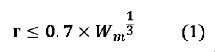
以下の関係(1)が満たされる、
態様1又は2の溶鋼の製造方法。
rは、前記酸素噴流の中心軸と前記溶鉄の表面との交点Oから、前記位置Pまでの距離(m)であり、
Wmは、前記溶鉄の重量(t)である。
<態様4>
溶鉄を処理するアーク炉であって、少なくとも1つの送酸手段と、少なくとも1つの副原料供給手段とを備え、
前記送酸手段は、前記アーク炉内の前記溶鉄の表面に向かって酸素噴流を噴射するように構成され、
前記副原料供給手段は、前記アーク炉内の前記溶鉄の表面の位置Pに向けて副原料を供給するように構成され、かつ、前記位置Pが前記酸素噴流と前記溶鉄との衝突面の外側の位置となるように構成される、
アーク炉。
The present application discloses the following aspects as one of the means for solving the above problems.
<Aspect 1>
A method for producing molten steel using an arc furnace equipped with an oxygen supplying means and an auxiliary raw material supplying means,
Injecting an oxygen jet from the oxygen supplying means onto the molten iron in the arc furnace, and supplying an auxiliary material from the auxiliary material supplying means toward a position P on the surface of the molten iron,
The position P is a position outside the collision surface between the oxygen jet and the molten iron.
A method for producing molten steel.
<Aspect 2>
The auxiliary material is a carbonaceous material.
2. A method for producing molten steel according to embodiment 1.
<Aspect 3>
The following relationship (1) is satisfied:
The method for producing molten steel according to aspect 1 or 2.
r is the distance (m) from an intersection O between the central axis of the oxygen jet and the surface of the molten iron to the position P,
Wm is the weight of the molten iron (t).
<Aspect 4>
An electric arc furnace for treating molten iron, comprising at least one oxygen supplying means and at least one auxiliary raw material supplying means,
The oxygen supplying means is configured to inject an oxygen jet toward a surface of the molten iron in the arc furnace,
The auxiliary material supplying means is configured to supply the auxiliary material toward a position P on the surface of the molten iron in the arc furnace, and is configured so that the position P is located outside a collision surface between the oxygen jet and the molten iron.
Arc furnace.
本開示の溶鋼の製造方法及びアーク炉によれば、アーク炉内の溶鉄に対して酸素噴流を噴射するとともに副原料を供給した場合に、目的とする反応を効率的に生じさせることができる。例えば、溶鉄に対して酸素噴流を噴射するとともに副原料としての炭材を供給した場合、溶鉄が効率的に脱窒され得る。 According to the molten steel manufacturing method and arc furnace disclosed herein, when an oxygen jet is injected onto the molten iron in the arc furnace and an auxiliary raw material is supplied, the target reaction can be efficiently caused. For example, when an oxygen jet is injected onto the molten iron and a carbonaceous material is supplied as an auxiliary raw material, the molten iron can be efficiently denitrified.
1.溶鋼の製造方法
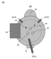
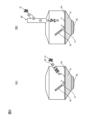
図面を参照しつつ、本開示の溶鋼の製造方法について説明する。ただし、本開示の溶鋼の製造方法は、図示される形態に限定されるものではない。図1~3に示されるように、一実施形態に係る溶鋼の製造方法は、送酸手段20と副原料供給手段30とを備えるアーク炉100を用いて溶鋼を製造する方法であって、前記送酸手段20から前記アーク炉100内の溶鉄10へと酸素噴流21を噴射するとともに、前記副原料供給手段30から前記溶鉄10の表面の位置Pに向けて副原料31を供給すること、を含む。ここで、前記位置Pは、前記酸素噴流21と前記溶鉄10との衝突面の外側の位置である。
1. Manufacturing method of molten steel The manufacturing method of molten steel of the present disclosure will be described with reference to the drawings. However, the manufacturing method of molten steel of the present disclosure is not limited to the form shown in the drawings. As shown in Figs. 1 to 3, the manufacturing method of molten steel according to one embodiment is a method of manufacturing molten steel using an
1.1 溶鉄
溶鉄10は、例えば、アーク炉100において、上部電極40と下部電極50との間にアークを生じさせて鉄源を溶解させることで得られる。鉄源は、例えば、スクラップ、還元鉄、型銑及び粒銑等の固体鉄源から選ばれる少なくとも1種を含むものであってよく、他の溶解炉や精錬炉で製造した溶鉄や溶鋼等を用いてもよい。溶鉄10は、鉄以外に様々な元素を含み得る。鉄以外の元素の組成は、鉄源の種類による。例えば、副原料31が供給される前の溶鉄10は、Cを0.02質量%以上3.0質量%以下含むものであってもよく、Nを0.005質量%以上0.030質量%以下含むものであってもよく、Pを0.003質量%以上0.1質量%以下含むものであってもよい。特に、本開示の製造方法において、副原料31として炭材を溶鉄10へと供給しつつ、酸素噴流21を噴射して脱炭とともに脱窒反応を生じさせる場合、脱炭反応において溶鉄10中の溶質炭素移動律速となる低炭素域において一層顕著な効果が得られる。本開示の製造方法において、副原料31として炭材を溶鉄10へと供給する場合、副原料31が供給される前の溶鉄10は、Cを0.02質量%以上3.0質量%以下含むものであってもよく、Nを0.005質量%以上0.030質量%以下含むものであってもよく、Pを0.003質量%以上0.1質量%以下含むものであってもよい。或いは、本開示の製造方法において、副原料31として炭材以外の副原料を溶鉄10へと供給する場合、脱炭反応が平衡論上困難となる極低炭素濃度域での実施を避けることが好ましく、例えば、副原料31が供給される前の溶鉄10は、Cを0.3質量%以上含むとことが好ましい。より具体的には、本開示の製造方法において、副原料31として炭材以外の副原料を溶鉄10へと供給する場合、副原料31が供給される前の溶鉄10は、Cを0.3質量%以上3.0質量%以下含むものであってもよく、Nを0.010質量%以上0.030質量%以下含むものであってもよく、Pを0.003質量%以上0.1質量%以下含むものであってもよい。溶鉄10の密度は、例えば、6600kg/m3以上7000kg/m3以下であってもよい。
1.1 Molten iron The
1.2 送酸手段
アーク炉100は、送酸手段20を少なくとも1つ備える。送酸手段20は、アーク炉100内の溶鉄10へと酸素噴流21を噴射する。送酸手段20は、ランスであってもよい。一つのランスから噴射される酸素噴流21の数は特に限定されない。例えば、ランスは、図2及び3に示されるような単孔ランスであってもよい。また、ランスはストレート形状であってもよいし、ラバール構造を有していてもよいし、気体燃料と支燃性ガスが酸素噴流を囲むようにして噴射されるコヒーレントバーナーを備えていてもよい。図1に示されるように、送酸手段20は、アーク炉100の炉蓋から挿入されるランス(いわゆるメインランス)、炉壁に設けられた壁ランス、及び、マニピュレータ等によって位置決めされる可変ランスのうちの少なくとも1つであってもよい。図2及び3に示されるように、アーク炉100においては、送酸手段20から溶鉄10の表面10xに向かって酸素が上吹きされる。これにより、後述の副原料31の種類に応じて、溶鉄10において脱炭反応や脱窒反応や脱燐反応等の各種の化学反応を生じさせることができる。
1.2 Oxygen supplying means The
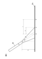
送酸手段20から噴射される酸素噴流21の形状は、送酸手段20の傾きや送酸手段20の噴射孔の形状等による。送酸手段20から噴射される酸素噴流21の向きは、鉛直方向に対して傾斜していてもよい。すなわち、図3に示されるように、送酸手段20から噴射される酸素噴流21の向きは、鉛直方向に対して角度θだけ傾けられていてもよい。傾斜角度θは、送酸手段20の中心軸と鉛直方向に平行な線とのなす角度として特定され得る。傾斜角度θは、例えば、5°以上30°以下であってもよい。また、図3に示されるように、酸素噴流21は、送酸手段20の噴射孔から一定の広がり角度αを有して溶鉄10へと噴射されてもよい。広がり角度αは、送酸手段20の噴射孔の形状等による。広がり角度αは、例えば、10°以上13°以下であってもよい。また、図3に示されるように、送酸手段20の噴射孔から溶鉄10の表面10xまでに一定の高さhが設けられていてもよい。尚、送酸手段20が鉛直方向に対して傾けられている場合、高さhは、送酸手段20の噴射孔の上端から溶鉄10の表面10xまでの距離をいうものとする。高さhは、例えば、0.2m以上0.8m以下であってもよい。また、図3に示されるように、送酸手段20は、孔径dの噴射孔を有するものであってよい。尚、孔径dは、噴射孔の円相当直径をいう。孔径dは、例えば、20mm以上100mm以下であってもよい。
The shape of the
一つの送酸手段20から噴射される酸素噴流21の流量は、特に限定されるものではなく、例えば、1000Nm3/h以上4000Nm3/h以下であってもよい。また、送酸手段20から噴射される酸素噴流21の流速(送酸手段20の噴射孔における流速であって、中心軸における流速)は、特に限定されるものではなく、例えば、10m/s以上300m/s以下であってもよい。
The flow rate of the
1.3 副原料供給手段
アーク炉100は、副原料供給手段30を少なくとも1つ備える。副原料供給手段30は、アーク炉100内の溶鉄10の表面の位置Pに向けて副原料を供給する。副原料は、例えば、アーク炉100に設けられた供給口を介して、炉内へと供給され得る。供給口は、炉のどの部分に設けられていてもよい。例えば、供給口は、炉内壁(側壁)に設けられた孔であってもよく、炉蓋に設けられた孔であってもよい。図3に示されるように、供給口は、溶鉄10の表面10xよりも上方に設置され得る。供給口の数は1つであってもよいし、複数であってもよい。
1.3 Auxiliary material supply means The
副原料供給手段30による副原料供給方式に特に制限はない。例えば、図2(A)に示されるような炉内壁に設けられた孔を介して副原料31を供給する方式、及び、図2(B)に示されるような炉蓋に設けられた孔を介して副原料31を供給する方式等が挙げられる。炉内壁又は炉蓋に設けられた孔と溶鉄10の表面10xにおける副原料31の供給位置Pとの位置関係等に応じて、適宜、ランスや投入シュート等が採用されてもよい。投入シュートとしては公知のものが採用されればよい。副原料供給手段30としてランスが採用される場合、副原料31は上吹きガスとともに溶鉄10へと供給されてもよい。この場合、副原料供給手段30からの上吹きガスは、溶鉄10の表面において火点を生じさせないものが採用されてもよいし、火点を生じさせるものが採用されてもよい。例えば、コストの観点から空気及びN2ガスのうちの一方又は両方が用いられることが好ましく、低窒素化の観点からは純酸素、Arガス及びCO2ガスなどから選ばれる少なくとも1種を用いることが好ましく、副原料が炭材や脱酸材などの場合は、鉄浴へ到達する以前に空中で消費されることを避けるために、より反応性の低いArガス及びCO2ガスのうちの一方又は両方を用いることが好ましい。このように、上吹きガスは製造条件に応じて選んでよく、これら操業制約の範囲内で少なくとも2種類以上のガスを所定の割合で混合したものであってもよい。上述の送酸手段20としてのランスと、副原料供給手段30としてのランスとは、互いに別のものである。
There is no particular limitation on the method of supplying the auxiliary material by the auxiliary
副原料31は、溶鉄10に対して、鉛直下向きに供給されてもよいし、斜め下向きに供給されてもよい。いずれにしても、副原料供給手段30は、所定の位置Pに向けて、副原料を供給する。ここで、「位置Pに向けて」とは、副原料31を供給する狙い位置が位置Pであることを意味し、副原料31の一部が拡散等によって位置P以外の部分に供給されてもよい。例えば、副原料31の一部が、酸素噴流21と溶鉄10との衝突面の内側に供給されてもよい。本開示の製造方法においては、副原料31の大部分、例えば50質量%以上、70質量%以上又は90質量%以上が、酸素噴流21と溶鉄10との衝突面の外側の位置Pに供給されるとよい。
The auxiliary
副原料供給手段30から供給される副原料31の量に特に制限はない。例えば、一つの副原料供給手段30から供給される副原料31の量は、10kg/min以上100kg/min以下であってもよい。
There is no particular limit to the amount of auxiliary
副原料供給手段30によって供給される副原料31の種類に特に制限はない。副原料31は、例えば、炭材であってもよいし、炭材以外の副原料であってもよい。炭材以外の副原料は、Ca含有材(石灰等)、Si含有材(珪砂等)、Al含有材(カルシウムアルミネート等)、Mg含有材(マグネシア等)等から選ばれる少なくとも1種であってよい。副原料31の形状は、副原料供給手段30から溶鉄10へと適切に供給可能な形状であればよく、粉体状、顆粒状、塊状等の種々の形状であってよい。また、副原料31は加圧成形品であってもよい。また、複数の副原料31を混合したものでもよい。副原料31は、例えば、0.1mm以上5mm以下の粒径を有するものであってよい。副原料31が大きい場合、一般的な製鋼設備が備える粉体の搬送系統を閉塞させ易くなるうえ、比表面積が小さくなるために伝熱性が悪化し、未溶解のまま溶鉄10上に滞留する時間が長くなりうる。一方で、副原料31が小さい場合、炉内での飛散性が高く、排ガス系統へ吸い込まれ易くなり、歩留まりで劣位となりうる。
There is no particular limit to the type of
本開示の製造方法においては、副原料31が火点外の所定の位置Pに向けて供給されることで、火点に供給される副原料31が低減され、火点の温度低下を抑制することができる。これにより、目的とする反応を効率的に生じさせることができる。また、本開示の製造方法において、副原料31が炭材である場合、酸素噴流21中で炭材が燃焼することによる歩留まりの低下が抑制され、さらに、炭材が火点外の所定の位置Pに向けて供給されることにより溶鉄10への着炭率が向上し、脱窒効率が顕著に向上し得る。
In the manufacturing method disclosed herein, the auxiliary
1.4 位置P
図2及び3に示されるように、位置Pは、酸素噴流21と溶鉄10との衝突面の外側となる位置である。好ましくは、図2に示されるように、副原料31は、酸素噴流21を横切ることなく、位置Pに供給される(言い換えれば、副原料31が副原料供給手段30から溶鉄10に至るまでの間に酸素噴流21が存在しないことが好ましい)。「酸素噴流21と溶鉄10との衝突面」は、上述の傾斜角度θ、広がり角度α、高さh、孔径dから幾何学的に特定され得る。例えば、図3に示されるように、送酸手段20の中心軸と溶鉄10の表面10xとの交点Oから、衝突面の外縁Xまでの距離zは、z=(tan(θ+α)-tanθ)h+d/(2cosθ)として特定され得る。図3に示されるように、酸素噴流21の中心軸と溶鉄10の表面10xとの交点Oから位置Pまでの距離rが、上記の距離zよりも大きければ、位置Pが酸素噴流21と溶鉄10との衝突面の外側となり得る。すなわち、本開示の製造方法において、酸素噴流21の中心軸と溶鉄10の表面10xとの交点Oから位置Pまでの距離rは、r>(tan(θ+α)-tanθ)h+d/(2cosθ)なる関係を満たすものであってもよい。
1.4 Position P
As shown in Figures 2 and 3, the position P is a position outside the collision surface between the
上述の通り、位置Pは、酸素噴流21と溶鉄10との衝突面の外側となる位置であればよく、上記の距離rの上限に特に制限はない。ただし、本開示の製造方法においては、距離rを溶鉄10の重量に基づいて計算される代表長よりも短くすることで、火点までの副原料31の移動が遅滞し難くなり、火点近傍の副原料濃度が向上し、目的とする反応をより効率的に生じさせることができるものと考えられる。副原料31が炭材である場合について考える。この場合、酸素噴流21によって溶鉄10からの脱炭が進行して、溶鉄10の炭素濃度が臨界炭素濃度を下回ると、脱炭反応による溶鉄10中の炭素の消費速度が反応サイトへの溶存炭素の供給速度を上回るため、送酸によって供給される酸素のうち脱炭に寄与する比率(脱炭酸素効率)が漸減し、火点におけるCO発生速度が低下して、脱窒において不利な状態となり得る。また、溶鉄10中のFeが過剰酸化されて、鉄歩留まりが低下したり、スラグ中のFeO濃度が上昇して、アーク炉100の耐火物を損耗させる虞もある。これに対し、距離rを溶鉄10の重量に基づいて計算される代表長よりも短くして、火点近傍の溶存炭素濃度を高めることで、溶存[N]の活量が上昇し、脱窒効率が一層向上し、さらには、Feの過剰酸化等も抑制されるものと考えられる。
As described above, the position P may be any position outside the collision surface between the
以上の観点から、副原料31を供給する位置Pは、各チャージにおける溶鉄10の重量から求められる鉄浴の代表長と、攪拌動力密度の値とを参照して決定されてもよい。例えば、公知文献である「浅井ら:鉄と鋼、68(1982)、vol.3、pp.426-434」によれば、流体の慣性支配域における代表流速は攪拌動力密度の1/3乗に比例するため、交点Oから位置Pまでの距離rがこの代表流速に対して十分に短ければ、火点への副原料31の供給の遅滞が緩和され、例えば、副原料31が炭材である場合、脱炭反応によるCOガス発生速度が高く維持され、脱窒に有利となる。すなわち、例えば、上吹きと底吹きの攪拌が支配的な炉に対して、以下の関係を満たすように距離rの上限を定めることができる。
From the above viewpoint, the position P for supplying the auxiliary
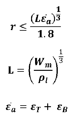
尚、攪拌動力密度は、上吹きや底吹きなどについて、例えば公知文献である「甲斐ら:鉄と鋼、69(1983)、vol.2、pp.228-237」や「森ら:鉄と鋼、67(1981)、vol.6、pp.672-695」等を参照し、線形和した値を採用すればよい。ここで攪拌を与える手段についてはガス供給によるものに限定されず、任意の手段について同様の取り扱いをすれば良いし、位置や原理が異なる攪拌手段の攪拌動力密度については、線形和でなくてもよく、各々独立した寄与率があるものとして扱ってもよい。 The stirring power density can be determined by linear summing the values for top and bottom blowing, etc., by referring to known literature such as Kai et al.: Tetsu-to-Haganen, vol. 69 (1983), pp. 228-237 and Mori et al.: Tetsu-to-Haganen, vol. 67 (1981), pp. 672-695. The means of stirring is not limited to gas supply, and any means can be treated in the same way. The stirring power density of stirring means with different positions and principles does not have to be a linear sum, and each can be treated as having an independent contribution rate.
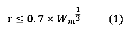
本発明者の知見によれば、本開示の製造方法において、以下の関係(1)が満たされることで、火点までの副原料31の移動が遅滞し難くなり、火点近傍の副原料濃度が向上し、目的とする反応をより効率的に生じさせ易くなる。
According to the inventor's findings, in the manufacturing method disclosed herein, by satisfying the following relationship (1), the movement of the auxiliary
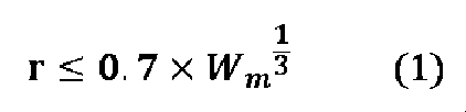
rは、酸素噴流21の中心軸と溶鉄10の表面10xとの交点Oから、上記の位置Pまでの距離(m)であり、
Wmは、溶鉄10の重量(t)である。
r is the distance (m) from the intersection O between the central axis of the
W m is the weight (t) of the
1.5 アーク炉におけるその他の構成
アーク炉100は、上述の通り、鉄源を溶解させる溶解炉を有する。溶解炉は、炉蓋、炉内壁及び炉底によって画定され得る部分である。溶解炉の平面形状は、図1に示されるような円形部を有するものであるとよい。溶解炉は一定の浴深さや一定の炉直径を有するものであってよい。溶解炉の浴深さや炉直径は、特に限定されるものではない。
1.5 Other configurations of the arc furnace As described above, the
アーク炉100は、上部電極40及び下部電極50を有するものであってもよい。アーク炉100が直流方式である場合、上部電極40が陰極、下部電極50が陽極となり得る。或いは、アーク炉100は交流方式であってもよい。上部電極40は、炉蓋を通して炉内に挿し込まれるように設置される。また、下部電極50は、炉底に設置される。上部電極40及び下部電極50の数は、各々、少なくとも1つである。上部電極40及び下部電極50の位置は、特に限定されるものではない。例えば、溶解炉における湯面形状が上面視(平面視)で略円形である場合、当該円形の中心位置が、1つの上部電極40や1つの下部電極50の中心軸と一致するようにしてもよい。或いは、上面視において、当該円形の中心位置の周囲に複数の上部電極40や複数の下部電極50が配置されるようにしてもよい。アーク炉100においては、例えば、不図示の電力供給部から上部電極40及び下部電極50へと電力が供給されて、上部電極40及び下部電極50の間にアークを生じさせる。電力供給部は、上部電極40及び下部電極50へ電力を供給するものとして一般的なものが採用されればよい。電力供給部から電極へと供給される電力は、電極間にアークを生じさせることができる限り、特に限定されるものではない。
The
図1に示されるように、アーク炉100は、溶解炉内へと鉄源を装入するための、鉄源装入手段60を備えていてもよい。また、アーク炉100は、溶鉄10の表面に生成したスラグ等を除滓するための、除滓扉70を備えていてもよい。さらに、アーク炉100は、溶鉄10又は溶鋼を出湯するための、偏心炉底出湯口80を備えていてもよい。これらはいずれも公知の構成が採用されればよい。
As shown in FIG. 1, the
アーク炉100は、各種の制御部を備え得る。制御部は、例えば、送酸手段20から溶鉄10へと噴射される酸素噴流21の位置に応じて、副原料供給手段30から溶鉄10へと供給される副原料31の供給位置Pを制御するものであってもよいし、或いは、副原料供給手段30から溶鉄10へと供給される副原料31の供給位置Pに応じて、送酸手段20から溶鉄10へと噴射される酸素噴流21の位置を制御するものであってもよし、或いは、送酸手段20から溶鉄10へと噴射される酸素噴流21の位置と、副原料供給手段30から溶鉄10へと供給される副原料31の供給位置Pとの双方を制御するものであってもよい。制御部は、上記の制御を実行可能なものであればよく、当該制御を実行可能するための公知の構成を備え得る。例えば、制御部は、CPU、RAM、ROM等を備えるものであってよい。
The
1.6 溶鋼
本開示の方法によって製造される溶鋼の組成は、特に限定されるものではない。本開示の製造方法においては、上述の通り、溶鉄10に対して、酸素噴流21が噴射されるとともに、副原料31が供給されるところ、副原料31の種類に応じて、溶鉄10の脱炭、脱窒、脱燐等が可能である。本開示の方法によって製造される溶鋼は、例えば、Cを0.01質量%以上3.0質量%以下含むものであってもよく、Nを0.002質量%以上0.030質量%以下含むものであってもよく、Pを0.003質量%以上0.1質量%以下含むものであってもよい。アーク炉100内の溶鋼は、例えば、上述の偏心炉底出湯口80を介して出鋼され得る。出鋼された溶鋼は、さらに精錬されてもよいし、或いは、そのまま連続鋳造等に供されてもよい。
1.6 Molten Steel The composition of the molten steel produced by the method of the present disclosure is not particularly limited. In the production method of the present disclosure, as described above, the
2.アーク炉
本開示の技術は、上記のような溶鋼の製造方法としての側面のほか、アーク炉としての側面も有する。すなわち、図1~3に示されるように、一実施形態に係るアーク炉100は、溶鉄10を処理するものであって、少なくとも1つの送酸手段20と、少なくとも1つの副原料供給手段30とを備える。ここで、前記送酸手段20は、前記アーク炉100内の前記溶鉄10の表面10xに向かって酸素噴流21を噴射するように構成されている。また、前記副原料供給手段30は、前記アーク炉100内の前記溶鉄10の表面10xの位置Pに向けて副原料31を供給するように構成され、かつ、前記位置Pが前記酸素噴流21と前記溶鉄10との衝突面の外側の位置となるように構成されている。送酸手段20や副原料供給手段30の詳細については上述の通りである。送酸手段20や副原料供給手段30は、例えば、上述の制御部によって制御されてもよい。すなわち、一実施形態に係るアーク炉100は、さらに制御部を備え、前記制御部は、前記送酸手段20が、前記アーク炉100内の溶鉄10へと酸素噴流21を噴射し、かつ、前記副原料供給手段30が、前記溶鉄10の表面の所定の位置Pに向けて副原料31を供給するように、前記送酸手段20及び前記副原料供給手段のうちの一方又は両方を制御するものであってもよい。
2. Arc Furnace The technology disclosed herein has an aspect as an arc furnace in addition to the aspect as a manufacturing method of molten steel as described above. That is, as shown in Figs. 1 to 3, an
3.作用効果
以下、副原料31として炭材が採用される場合を中心に、本開示の溶鋼の製造方法による作用効果についてさらに補足する。
3. Effects and Benefits The effects and benefits of the method for producing molten steel according to the present disclosure will be further supplemented below, focusing on the case where a carbonaceous material is used as the auxiliary
上述の通り、副原料として炭材が採用される場合、送酸脱炭とともに脱窒反応を生じさせることができる。ここで、一般的な送酸脱炭時の吸脱窒速度を支配する因子には、少なくとも、
(1)火点におけるCO発生速度
(2)火点におけるC-O反応サイトの温度
(3)CO気泡と溶鉄との間の気液反応界面積
が含まれるものと考えられる。このほか、酸素噴流が巻き込む空気(ソフトブローで火点への連行量増大)や、溶鉄中の界面活性成分濃度([S]、[O]が高いと反応速度低下)等も挙げられる。
As described above, when carbonaceous materials are used as the auxiliary raw material, denitrification can occur along with oxygen-flow decarbonization. Here, the factors governing the rate of adsorption and denitrification during general oxygen-flow decarbonization include at least the following:
These factors are thought to include (1) the rate of CO generation at the fire point, (2) the temperature of the C-O reaction site at the fire point, and (3) the area of the gas-liquid reaction interface between the CO bubbles and the molten iron. Other factors include the air entrained by the oxygen jet (soft blowing increases the amount of air entrained to the fire point), and the concentration of surface active components in the molten iron (high [S] and [O] decrease the reaction rate).
従来においては、主にスラグフォーミングの促進などを目的として、アーク炉における酸素噴流及び炭材の同時吹込みが実施されているが、この場合は両者が溶鉄表面の同じ位置に吹き込まれる。すなわち、炭材を酸素噴流に合流させ、炭素と酸素とを溶鉄表面の一か所に集中的に供給することにより、スラグ中で確実にCOガスを発生させ、スラグのフォーミング状態を安定化させる。しかしながら、炭材と酸素とが溶鉄表面の同じ位置に吹き込まれる場合、吸脱窒反応の観点からみると、
(1)C-O反応サイトが火点のみならずスラグ中あるいは空気中へも分散してしまうため、火点におけるCO発生速度が低下し、
(2)室温に近い炭材が火点に直接投入されることとなるため、火点におけるC-O反応サイトの温度も低下し、
(3)C-O反応サイトが火点のみならずスラグ中あるいは空気中へも分散してしまうため、溶鉄からの脱炭量が減少し、CO気泡と溶鉄との間の気液反応界面積も減少する。以上の通り、従来の方法では、脱窒反応速度の低下を招く。
Conventionally, oxygen jets and carbonaceous materials have been simultaneously injected into electric arc furnaces mainly for the purpose of promoting slag foaming, but in this case, both are injected into the same position on the molten iron surface. In other words, by merging the carbonaceous materials with the oxygen jets and intensively supplying carbon and oxygen to one location on the molten iron surface, CO gas is reliably generated in the slag and the foaming state of the slag is stabilized. However, when the carbonaceous materials and oxygen are injected into the same position on the molten iron surface, from the viewpoint of the adsorption and denitrification reaction,
(1) The CO reaction site is dispersed not only at the fire point but also in the slag or air, so the rate of CO generation at the fire point decreases.
(2) Since the carbonaceous material is close to room temperature and is directly charged to the fire point, the temperature of the C-O reaction site at the fire point also decreases.
(3) The C-O reaction sites are dispersed not only at the hot points but also in the slag or air, reducing the amount of decarburization from the molten iron and reducing the gas-liquid reaction interface area between the CO bubbles and the molten iron. As described above, the conventional method leads to a decrease in the denitrification reaction rate.
これに対し、本開示の溶鋼の製造方法によれば、溶鉄10へと酸素噴流21が噴射される場合に、酸素噴流21と溶鉄10との衝突面の外側(すなわち、火点範囲の外側)の位置Pに向けて副原料31としての炭材が供給されることで、
(1)C-O反応サイトが火点に集中し、火点におけるCO発生速度が増加し、
(2)室温に近い炭材が火点範囲外に投入されて、火点におけるC-O反応サイトの温度低下が抑制され、
(3)C-O反応サイトが火点に集中し、溶鉄からの脱炭量が増加し、CO気泡と溶鉄との間の気液反応界面積が増加する。これにより、脱窒反応速度を増加させることができるものと考えられる。
In contrast, according to the method for producing molten steel of the present disclosure, when the
(1) C-O reaction sites are concentrated at the fire point, increasing the rate of CO generation at the fire point;
(2) Carbonaceous material close to room temperature is added outside the range of the ignition point, suppressing the temperature drop of the C-O reaction site at the ignition point;
(3) The CO reaction sites are concentrated at the hot points, the amount of carbon removed from the molten iron increases, and the gas-liquid reaction interface area between the CO bubbles and the molten iron increases, which is thought to increase the denitrification reaction rate.
尚、火点温度の低下を抑制できるという効果は、副原料31の種類によらず発揮される。すなわち、本開示の製造方法によれば、副原料31の種類によらず、火点に直接供給される副原料31の量を低減することができ、火点の温度が低下し難く、目的とする反応を効率的に生じさせることができる。
The effect of suppressing the drop in the ignition point temperature is exerted regardless of the type of auxiliary
以下、実施例を示しつつ本発明についてさらに説明するが、本発明は以下の実施例に限定されるものではない。本発明は、その要旨を逸脱せず、その目的を達する限りにおいては、種々の条件を採用可能とするものである。 The present invention will be further explained below with reference to examples, but the present invention is not limited to the following examples. The present invention allows various conditions to be adopted as long as the purpose is achieved without departing from the gist of the invention.
本実施例においては、下記の構成(1)~(6)を有するアーク炉において、冷鉄源としてスクラップを使用して溶鋼の溶製を行った。
(1)溶解炉の炉殻径が7mである。
(2)一度に処理可能な最大溶鉄量が200tである。
(3)3本の上部黒鉛電極を用いる三相交流式である。
(4)送酸用壁ランス2本と、送粉用壁ランス2本とを炉壁に固定するように備える。
(5)炉外から炉内へと挿入可能なマニピュレータ(可動式アーム)を備え、マニピュレータが送酸用可変ランスと送粉用可変ランスとを備える。
(6)炉底に底吹き羽口を3か所備える。
In this example, molten steel was produced in an electric arc furnace having the following configurations (1) to (6) using scrap as a cold iron source.
(1) The diameter of the melting furnace shell is 7 m.
(2) The maximum amount of molten iron that can be processed at one time is 200 tons.
(3) It is a three-phase AC type that uses three upper graphite electrodes.
(4) Two wall lances for supplying oxygen and two wall lances for supplying powder are provided and fixed to the furnace wall.
(5) A manipulator (movable arm) is provided that can be inserted into the furnace from outside the furnace, and the manipulator is provided with a variable lance for supplying oxygen and a variable lance for supplying powder.
(6) The hearth is equipped with three bottom-blowing tuyeres.
本実施例においては、常法の電気炉操業方法を採用した。送酸と副原料との供給は、それぞれ1か所ずつから実施し、各供給量は1,000~4,000Nm3/h、0.01~0.10t/minであり、使用するランスや副原料の供給位置、供給量のレンジを適宜変更した。 In this embodiment, a conventional electric furnace operation method was adopted. The oxygen supply and auxiliary materials were each supplied from one location, with the respective supply amounts being 1,000 to 4,000 Nm3 /h and 0.01 to 0.10 t/min. The lances used, the supply positions of the auxiliary materials, and the ranges of the supply amounts were appropriately changed.
具体的には、各チャージにおいて、装入した冷鉄源がすべて溶解したことを炉体側部の除滓口より目視で確認したのちに、炉内壁に設置された固定式の粉体ランスより副原料としての炭材を供給し、除滓口より炉内へと挿入した可動式の送酸ランスから酸素ガスを同時に供給した。火点の範囲は図3に示される関係から幾何学的に求め、送酸ランスの中心軸と溶鉄の表面の交点Oから副原料の供給狙い位置Pまでの距離rと、交点Oから火点範囲の外縁までの距離zとの差Δrが所定の値となるように、可動式の送酸ランスの装入位置と吹込み角度とを逐次調整した。Δrがプラスである場合、供給狙い位置Pが火点範囲の外側となり、マイナスである場合、供給狙い位置Pが火点範囲の内側となる。尚、本実施例では、Δrが小さくなるほど、可動ランスを寝かせる(角度θを大きくする)必要があり、結果として距離zが大きくなる傾向にあった。また、溶鉄重量が小さいほど、湯面が低くなり、高さhが大きくなって、距離zが大きくなる傾向にあった。送酸及び送炭の開始前後にサンプリングを実施して化学分析に供し、分析により得られた同一チャージ内の窒素濃度変化Δ[N]から各水準の優劣評価を行った。評価指標は以下の通りである。
◎:Δ[N]≦-30ppm
○:-30ppm<Δ[N]≦-20ppm
△:-20ppm<Δ[N]≦-10ppm
×:-10ppm<Δ[N]
Specifically, in each charge, after visually confirming that all the charged cold iron source had melted through the slag removal port on the side of the furnace body, carbonaceous material was supplied as an auxiliary material from a fixed powder lance installed on the furnace inner wall, and oxygen gas was simultaneously supplied from a movable oxygen supply lance inserted into the furnace through the slag removal port. The range of the fire point was geometrically determined from the relationship shown in Figure 3, and the charging position and blowing angle of the movable oxygen supply lance were sequentially adjusted so that the difference Δr between the distance r from the intersection O of the central axis of the oxygen supply lance and the surface of the molten iron to the auxiliary material supply target position P and the distance z from the intersection O to the outer edge of the fire point range was a predetermined value. When Δr is positive, the supply target position P is outside the fire point range, and when it is negative, the supply target position P is inside the fire point range. In this embodiment, the smaller Δr is, the more it is necessary to lay the movable lance down (the angle θ is increased), and as a result, the distance z tends to be larger. In addition, the smaller the weight of the molten iron, the lower the molten iron surface, the larger the height h, and the larger the distance z. Sampling was carried out before and after the start of oxygen and coal feeding and was subjected to chemical analysis, and the superiority or inferiority of each level was evaluated based on the nitrogen concentration change Δ[N] within the same charge obtained by the analysis. The evaluation indexes are as follows.
◎:Δ[N]≦-30ppm
○: -30ppm<Δ[N]≦-20ppm
△: -20ppm<Δ[N]≦-10ppm
×: -10ppm<Δ[N]
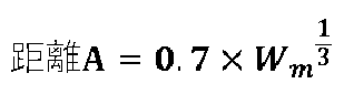
下記表1に、各実施例と比較例の試験条件とΔ[N]に係る評価結果とを示す。尚、下記表1において、「距離A」とは溶鉄の重量Wm(t)を用いた下記式によって求められる値である。 The test conditions and evaluation results for Δ[N] for each of the examples and comparative examples are shown in Table 1. In Table 1, "distance A" is a value calculated by the following formula using the weight W m (t) of molten iron.

尚、本実施例及び比較例においては固定式の壁ランスから副原料を吹込み、除滓口から挿入した可動式ランスから送酸を行ったが、各水準について壁ランスから送酸し、可動式ランスから副原料を供給した場合も、Δ[N]に優位な差は認められず、上記表1に示すものと同様の結果であった。また、装入する冷鉄源の量を調整することで溶鉄量を変化させたが、その場合は固定式の壁ランスと湯面との幾何学的位置関係などが変化しないように、耐火物の配置を変更して調整した。 In this embodiment and comparative example, the auxiliary materials were blown in from the fixed wall lance and oxygen was fed from the movable lance inserted from the slag removal port. However, even when oxygen was fed from the wall lance and the auxiliary materials were supplied from the movable lance for each level, no significant difference in Δ[N] was observed, and the results were similar to those shown in Table 1 above. In addition, the amount of molten iron was changed by adjusting the amount of cold iron source charged. In this case, the arrangement of the refractories was changed to adjust so that the geometric positional relationship between the fixed wall lance and the molten metal surface would not change.
各水準では、初回サンプリングの結果が[C]=0.48~0.52%であり、2回目のサンプリングの結果が[C]=0.04~0.06%であり、鉄浴由来の脱炭量は概ね同等であった。[N]については初回サンプリングの結果が[N]=0.0070~0.0075%であった。副原料として炭材を吹き付ける場合は、炭素源が外部より連続的に供給されるため、鉄浴由来の炭素量にかかわらず所望の効果が発揮された。一方で、実施例1、2、比較例1、2においては、副原料として炭材以外のものを用いたため、鉄浴由来の脱炭反応のみが脱窒に寄与したと考えられる。 At each level, the results of the first sampling were [C] = 0.48-0.52%, and the results of the second sampling were [C] = 0.04-0.06%, so the amount of decarburization derived from the iron bath was roughly the same. The results of the first sampling for [N] were [N] = 0.0070-0.0075%. When carbonaceous material was sprayed as an auxiliary material, the carbon source was continuously supplied from the outside, so the desired effect was achieved regardless of the amount of carbon derived from the iron bath. On the other hand, in Examples 1 and 2 and Comparative Examples 1 and 2, something other than carbonaceous material was used as an auxiliary material, so it is thought that only the decarburization reaction derived from the iron bath contributed to denitrification.
表1に示される結果から、アーク炉において、送酸手段から炉内の溶鉄へと酸素噴流を噴射するとともに、副原料供給手段から溶鉄の表面の位置Pに向けて副原料を供給する場合は、当該位置Pが火点範囲の外側、すなわち、酸素噴流と溶鉄との衝突面の外側である場合(実施例1~16)に、内側である場合(比較例1~3)よりも、窒素濃度の低い溶鋼が製造できるといえる。また、実施例1、2と実施例3~16との比較から、副原料が炭材である場合に、窒素濃度のより低い溶鋼が製造できるといえる。さらに、実施例3~16の結果から、以下の関係(1)が満たされる場合に、窒素濃度のさらに低い溶鋼が製造できるといえる。 From the results shown in Table 1, in an arc furnace, when an oxygen jet is injected from an oxygen supplying means into the molten iron in the furnace and an auxiliary material is supplied from an auxiliary material supplying means toward position P on the surface of the molten iron, it can be said that molten steel with a lower nitrogen concentration can be produced when position P is outside the fire point range, i.e., outside the collision surface between the oxygen jet and the molten iron (Examples 1 to 16), than when it is inside (Comparative Examples 1 to 3). Also, from a comparison of Examples 1 and 2 with Examples 3 to 16, it can be said that molten steel with an even lower nitrogen concentration can be produced when the auxiliary material is carbonaceous material. Furthermore, from the results of Examples 3 to 16, it can be said that molten steel with an even lower nitrogen concentration can be produced when the following relationship (1) is satisfied.
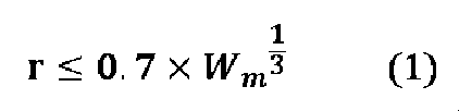
rは、酸素噴流の中心軸と溶鉄の表面との交点Oから、上記の位置Pまでの距離(m)であり、
Wmは、溶鉄の重量(t)である。
r is the distance (m) from the intersection O between the central axis of the oxygen jet and the surface of the molten iron to the position P,
W m is the weight of molten iron (t).
100 アーク炉
10 溶鉄
10x 溶鉄の表面(湯面)
20 送酸手段
21 酸素噴流
30 副原料供給手段
31 副原料
40 上部電極
50 下部電極
60 鉄源装入手段
70 除滓扉
80 偏心炉底出湯口
100
20: Oxygen supply means 21: Oxygen jet 30: Auxiliary material supply means 31: Auxiliary material 40: Upper electrode 50: Lower electrode 60: Iron source charging means 70: Slag removal door 80: Eccentric furnace bottom tapping port
Claims (4)
前記送酸手段から前記アーク炉内の溶鉄へと酸素噴流を噴射するとともに、前記副原料供給手段から前記溶鉄の表面の位置Pに向けて副原料を供給すること、を含み、
前記位置Pが、前記酸素噴流と前記溶鉄との衝突面の外側の位置である、
溶鋼の製造方法。 A method for producing molten steel using an arc furnace equipped with an oxygen supplying means and an auxiliary raw material supplying means,
Injecting an oxygen jet from the oxygen supplying means onto the molten iron in the arc furnace, and supplying an auxiliary material from the auxiliary material supplying means toward a position P on the surface of the molten iron,
The position P is a position outside the collision surface between the oxygen jet and the molten iron.
A method for producing molten steel.
請求項1に記載の溶鋼の製造方法。 The auxiliary material is a carbonaceous material.
The method for producing molten steel according to claim 1 .
請求項1又は2に記載の溶鋼の製造方法。
rは、前記酸素噴流の中心軸と前記溶鉄の表面との交点Oから、前記位置Pまでの距離(m)であり、
Wmは、前記溶鉄の重量(t)である。 The following relationship (1) is satisfied:
The method for producing molten steel according to claim 1 or 2.
r is the distance (m) from an intersection O between the central axis of the oxygen jet and the surface of the molten iron to the position P,
Wm is the weight of the molten iron (t).
前記送酸手段は、前記アーク炉内の前記溶鉄の表面に向かって酸素噴流を噴射するように構成され、
前記副原料供給手段は、前記アーク炉内の前記溶鉄の表面の位置Pに向けて副原料を供給するように構成され、かつ、前記位置Pが前記酸素噴流と前記溶鉄との衝突面の外側の位置となるように構成される、
アーク炉。 An electric arc furnace for treating molten iron, comprising at least one oxygen supplying means and at least one auxiliary raw material supplying means,
The oxygen supplying means is configured to inject an oxygen jet toward a surface of the molten iron in the arc furnace,
The auxiliary material supplying means is configured to supply the auxiliary material toward a position P on the surface of the molten iron in the arc furnace, and is configured so that the position P is located outside a collision surface between the oxygen jet and the molten iron.
Arc furnace.
Priority Applications (5)
| Application Number | Priority Date | Filing Date | Title |
|---|---|---|---|
| JP2023042074A JP2024131663A (en) | 2023-03-16 | 2023-03-16 | Molten steel manufacturing method and electric arc furnace |
| KR1020257029498A KR20250141813A (en) | 2023-03-16 | 2024-03-15 | Method for manufacturing molten steel and arc furnace |
| PCT/JP2024/010322 WO2024190908A1 (en) | 2023-03-16 | 2024-03-15 | Method for producing molten steel and arc furnace |
| CN202480019113.8A CN120813709A (en) | 2023-03-16 | 2024-03-15 | Method for producing molten steel and electric arc furnace |
| EP24771010.6A EP4682272A1 (en) | 2023-03-16 | 2024-03-15 | Method for producing molten steel and arc furnace |
Applications Claiming Priority (1)
| Application Number | Priority Date | Filing Date | Title |
|---|---|---|---|
| JP2023042074A JP2024131663A (en) | 2023-03-16 | 2023-03-16 | Molten steel manufacturing method and electric arc furnace |
Publications (1)
| Publication Number | Publication Date |
|---|---|
| JP2024131663A true JP2024131663A (en) | 2024-09-30 |
Family
ID=92900566
Family Applications (1)
| Application Number | Title | Priority Date | Filing Date |
|---|---|---|---|
| JP2023042074A Pending JP2024131663A (en) | 2023-03-16 | 2023-03-16 | Molten steel manufacturing method and electric arc furnace |
Country Status (1)
| Country | Link |
|---|---|
| JP (1) | JP2024131663A (en) |
-
2023
- 2023-03-16 JP JP2023042074A patent/JP2024131663A/en active Pending
Similar Documents
| Publication | Publication Date | Title |
|---|---|---|
| KR0159180B1 (en) | Steelmaking method | |
| JPWO2013094634A1 (en) | Converter steelmaking method | |
| JP2023004698A (en) | Electric furnace and electric furnace steel making method | |
| CN109790590B (en) | Dephosphorization treatment device and dephosphorization method of molten iron using the device | |
| JPH1180825A (en) | Top blowing lance for converter refining and converter refining method using the same | |
| JP2024131663A (en) | Molten steel manufacturing method and electric arc furnace | |
| JP2025136501A (en) | Converter refining method | |
| JP5870771B2 (en) | Manufacturing method of molten steel | |
| JP4715384B2 (en) | Method for dephosphorizing hot metal and top blowing lance for dephosphorization | |
| WO2024190908A1 (en) | Method for producing molten steel and arc furnace | |
| JP2024141869A (en) | Molten steel manufacturing method | |
| JP2025076842A (en) | Molten steel manufacturing method and electric arc furnace | |
| JP2013209746A (en) | Method for refining molten iron in converter type refining furnace | |
| JP5585633B2 (en) | Method of refining hot metal in converter | |
| JP2013087316A (en) | Powder injection lance with burner function, and method for refining molten iron using powder injection lance and method for smelting reduction of molten metal | |
| JP6726777B1 (en) | Method for producing low carbon ferromanganese | |
| JP4120161B2 (en) | Operation method of iron bath smelting reduction furnace | |
| JP3665600B2 (en) | Hot metal dephosphorization method | |
| JPS62247014A (en) | Carburizing, melting and refining method | |
| JP4513340B2 (en) | Hot metal dephosphorization method | |
| JP5304816B2 (en) | Manufacturing method of molten steel | |
| JPH0873915A (en) | Dephosphorization and desulfurization refining method of hot metal | |
| JP2006188769A (en) | Method for producing low phosphorus hot metal | |
| JPH0860221A (en) | Converter steelmaking | |
| JP6327298B2 (en) | Hot metal refining method |
Legal Events
| Date | Code | Title | Description |
|---|---|---|---|
| A621 | Written request for application examination |
Free format text: JAPANESE INTERMEDIATE CODE: A621 Effective date: 20251112 |