JP2024141663A - Power Supplies - Google Patents

Power Supplies Download PDF

Info

Publication number
JP2024141663A
JP2024141663A JP2023053443A JP2023053443A JP2024141663A JP 2024141663 A JP2024141663 A JP 2024141663A JP 2023053443 A JP2023053443 A JP 2023053443A JP 2023053443 A JP2023053443 A JP 2023053443A JP 2024141663 A JP2024141663 A JP 2024141663A
Authority
JP
Japan
Prior art keywords
leg
power
switching element
conversion unit
winding
Prior art date
Legal status (The legal status is an assumption and is not a legal conclusion. Google has not performed a legal analysis and makes no representation as to the accuracy of the status listed.)
Pending
Application number
JP2023053443A
Other languages
Japanese (ja)
Inventor
雄太 森本
Yuta Morimoto
真 田口
Makoto Taguchi
Current Assignee (The listed assignees may be inaccurate. Google has not performed a legal analysis and makes no representation or warranty as to the accuracy of the list.)
Aisin Corp
Original Assignee
Aisin Corp
Priority date (The priority date is an assumption and is not a legal conclusion. Google has not performed a legal analysis and makes no representation as to the accuracy of the date listed.)
Filing date
Publication date
Application filed by Aisin Corp filed Critical Aisin Corp
Priority to JP2023053443A priority Critical patent/JP2024141663A/en
Publication of JP2024141663A publication Critical patent/JP2024141663A/en
Pending legal-status Critical Current

Links

Images

Landscapes

  • Inverter Devices (AREA)
  • Electric Propulsion And Braking For Vehicles (AREA)
  • Control Of Ac Motors In General (AREA)
  • Dc-Dc Converters (AREA)

Abstract

To provide a power supply that can reduce manufacturing costs.SOLUTION: A power supply 1 includes an on-board charger 101 that charges a battery 3, a first motor drive unit 102 that drives a permanent magnet motor M1, and a second motor drive unit 109 that drives a wound field motor M2. The on-board charger 101 includes an AC/DC conversion unit that converts AC power into DC power, and a converter having a first conversion unit, a second conversion unit, and a transformer. The first conversion unit inputs the DC power from the AC/DC conversion unit to a primary winding of the transformer, and the second conversion unit converts the AC power from the secondary winding of the transformer into DC power that can charge the battery 3. The second conversion unit and a field winding current supply unit that supplies current to the field winding of the wound field motor M2, a first inverter that supplies a current to the permanent magnet motor M1, and a second inverter that supplies a current to a stator coil of the wound field motor M2 have the same circuit configuration and use the same electronic components.SELECTED DRAWING: Figure 1

Description

本発明は、車両に搭載される電源装置に関する。 The present invention relates to a power supply device mounted on a vehicle.

従来、様々なモータが利用されている。このようなモータとして、例えばロータに界磁巻線を有し、ステータにステータコイルを有する巻線界磁モータがある。下記に出典を示す特許文献1に記載の回転電機の制御装置は、車両に搭載されるバッテリからの出力に基づいて、ステータのステータコイルに電力供給を行うインバータと、当該バッテリからの出力に基づいて、界磁巻線に電力供給を行う界磁通電回路とを備えている。インバータは、モータの相数に応じて3つのレグを有して構成され、界磁通電回路は、界磁巻線を流れる電流の方向を変更可能に2つのレグを有して構成されている。 Conventionally, various motors have been used. For example, one such motor is a wound field motor having a field winding on the rotor and a stator coil on the stator. The control device for a rotating electric machine described in Patent Document 1, cited below, includes an inverter that supplies power to the stator coil of the stator based on the output from a battery mounted on the vehicle, and a field current circuit that supplies power to the field winding based on the output from the battery. The inverter is configured with three legs according to the number of phases of the motor, and the field current circuit is configured with two legs that can change the direction of the current flowing through the field winding.

また、車両に搭載されるバッテリには、特許文献2に記載されるような充電器を用いて外部からの電力に基づいて充電可能に構成されているものがある。 Some batteries installed in vehicles are configured to be rechargeable from external power using a charger such as that described in Patent Document 2.

特開2019-71733号公報JP 2019-71733 A 特開2017-158322号公報JP 2017-158322 A

例えば、車両においては、特許文献1に記載されるような巻線界磁モータ、及び巻線界磁モータとは異なる永久磁石モータの双方を設けることが考えられる。また、このような巻線界磁モータ、及び巻線界磁モータが設けられた車両において、特許文献2に記載される充電器を設けることも考えられる。このような場合、回路規模が大きくなり、使用する部品の種類が多くなる。このため、部品管理コストが増大し、製造コストを低減する上で改善の余地がある。 For example, it is conceivable to provide a vehicle with both a wound field motor as described in Patent Document 1 and a permanent magnet motor different from the wound field motor. It is also conceivable to provide a charger as described in Patent Document 2 in such a wound field motor and a vehicle equipped with a wound field motor. In such a case, the circuit scale becomes large and the number of types of parts used increases. This increases the cost of managing parts, and there is room for improvement in reducing manufacturing costs.

そこで、製造コストを低減可能な電源装置が求められる。 Therefore, there is a demand for a power supply device that can reduce manufacturing costs.

本発明に係る電源装置の特徴構成は、車両に搭載されるバッテリを、外部からの交流電力により充電する車載用充電器と、前記車両に搭載される永久磁石モータを駆動する第1モータ駆動部と、前記車両に搭載される巻線界磁モータを駆動する第2モータ駆動部と、を備え、前記車載用充電器が、前記交流電力を直流電力に変換する交直変換部と、当該交直変換部にて変換された前記直流電力を、前記バッテリを充電可能な直流電力に変換するコンバータと、を有し、前記コンバータは、第1変換部と第2変換部とトランスとを有し、前記第1変換部は、前記交直変換部からの前記直流電力を前記トランスの一次巻線に入力し、前記第2変換部は、前記トランスの二次巻線からの交流電力を、第1回路構成及び第1電子部品により前記バッテリを充電可能な直流電力に変換し、前記第1モータ駆動部は、第2回路構成及び第2電子部品により前記永久磁石モータのステータコイルに通電する第1インバータを備え、前記第2モータ駆動部は、第1回路構成及び第1電子部品により前記巻線界磁モータの界磁巻線に通電する界磁巻線通電部、及び第2回路構成及び第2電子部品によりステータコイルに通電する第2インバータを備え、前記第2変換部と前記界磁巻線通電部とは、回路構成及び使用される電子部品が互いに同一であり、前記第1インバータと前記第2インバータとは、回路構成及び使用される電子部品が互いに同一である点にある。 The characteristic configuration of the power supply device according to the present invention includes an on-board charger that charges a battery mounted on a vehicle with AC power from an external source, a first motor drive unit that drives a permanent magnet motor mounted on the vehicle, and a second motor drive unit that drives a wound field motor mounted on the vehicle, and the on-board charger has an AC/DC conversion unit that converts the AC power to DC power, and a converter that converts the DC power converted by the AC/DC conversion unit into DC power capable of charging the battery, and the converter has a first conversion unit, a second conversion unit, and a transformer, and the first conversion unit inputs the DC power from the AC/DC conversion unit to a primary winding of the transformer, and the second conversion unit converts the DC power from the secondary winding of the transformer The AC power from the permanent magnet motor is converted into DC power capable of charging the battery by a first circuit configuration and a first electronic component, the first motor drive unit includes a first inverter that energizes the stator coil of the permanent magnet motor by a second circuit configuration and a second electronic component, the second motor drive unit includes a field winding energization unit that energizes the field winding of the wound field motor by a first circuit configuration and a first electronic component, and a second inverter that energizes the stator coil by a second circuit configuration and a second electronic component, the second conversion unit and the field winding energization unit have the same circuit configuration and electronic components used, and the first inverter and the second inverter have the same circuit configuration and electronic components used.

このような特徴構成とすれば、電源装置において、使用される電子部品の種類を少なくすることができるので、部品管理コストを低減できる。したがって、電源装置の製造コストを低減することが可能となる。 With this type of characteristic configuration, the number of electronic components used in the power supply device can be reduced, reducing component management costs. This makes it possible to reduce the manufacturing costs of the power supply device.

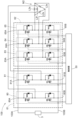
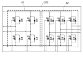
車両における電源装置及びバッテリの配置状態を示す図である。FIG. 2 is a diagram showing an arrangement of a power supply device and a battery in a vehicle. 車載用充電器及び第1モータ駆動部の回路図である。FIG. 2 is a circuit diagram of an in-vehicle charger and a first motor driving unit. 車載用充電器及び第1モータ駆動部の回路図である。FIG. 2 is a circuit diagram of an in-vehicle charger and a first motor driving unit. 第2モータ駆動部の回路図である。FIG. 4 is a circuit diagram of a second motor drive unit. 第1基板を示す図である。FIG. 第2基板を示す図である。FIG.

本発明に係る電源装置は、車両に搭載される永久磁石モータを駆動すると共に、車両に搭載されるバッテリを充電し、且つ、車両に搭載される巻線界磁モータを駆動する。また、電源装置は、バッテリの出力に基づいて交流電力を出力することができるように構成される。以下、本実施形態の電源装置1について説明する。 The power supply device according to the present invention drives a permanent magnet motor mounted on a vehicle, charges a battery mounted on the vehicle, and drives a wound field motor mounted on the vehicle. The power supply device is also configured to be able to output AC power based on the output of the battery. The power supply device 1 of this embodiment will be described below.

図1は、車両100における電源装置1及びバッテリ3の配置状態を示す図である。図1に示されるように、車両100には、電源装置1、バッテリ3、バッテリ5、リア側トランスアクスル(Rr T/A)TA1、永久磁石モータM1、フロント側トランスアクスル(Fr T/A)TA2、及び巻線界磁モータM2が備えられる。 Figure 1 is a diagram showing the arrangement of a power supply device 1 and a battery 3 in a vehicle 100. As shown in Figure 1, the vehicle 100 is equipped with a power supply device 1, a battery 3, a battery 5, a rear transaxle (Rr T/A) TA1, a permanent magnet motor M1, a front transaxle (Fr T/A) TA2, and a wound field motor M2.

本実施形態では、バッテリ3は、車両100における前後方向の中央に設けられ、バッテリ5は、車両100における前後方向の前側に設けられる。バッテリ3は、車両100の走行させる動力源となる電力を供給する、例えば数百〔V〕の直流電圧を出力する。バッテリ5は、車両100に搭載される装置に電力を供給する、例えば12〔V〕の直流電圧を出力する。 In this embodiment, battery 3 is provided in the center of vehicle 100 in the longitudinal direction, and battery 5 is provided at the front of vehicle 100 in the longitudinal direction. Battery 3 outputs a DC voltage of, for example, several hundred volts to supply power as a power source for driving vehicle 100. Battery 5 outputs a DC voltage of, for example, 12 volts to supply power to devices mounted on vehicle 100.

永久磁石モータM1は、車両100における前後方向の後側に設けられる。巻線界磁モータM2は、車両100における前後方向の前側に設けられる。永久磁石モータM1の回転力はリア側トランスアクスルTA1に伝達され、リア側トランスアクスルTA1を介して後輪RTが駆動される。巻線界磁モータM2の回転力はフロント側トランスアクスルTA2に伝達され、フロント側トランスアクスルTA2を介して前輪FTが駆動される。 The permanent magnet motor M1 is provided at the rear of the vehicle 100 in the longitudinal direction. The wound field motor M2 is provided at the front of the vehicle 100 in the longitudinal direction. The rotational force of the permanent magnet motor M1 is transmitted to the rear transaxle TA1, and the rear wheels RT are driven via the rear transaxle TA1. The rotational force of the wound field motor M2 is transmitted to the front transaxle TA2, and the front wheels FT are driven via the front transaxle TA2.

電源装置1は、制御部50(図1では不図示であって、図2参照)と、車載用充電器101と、第1モータ駆動部102と、第2モータ駆動部109とを備える。車載用充電器101は、車両100に搭載されるバッテリ3及びバッテリ5を、外部からの交流電力により充電する。車載用充電器101には、車両100に設けられる充電口2から交流電力が供給される。詳細は後述するが、車載用充電器101はバッテリ3及びバッテリ5を充電する。したがって、車載用充電器101は、バッテリ3及びバッテリ5に電気的に接続される。また、車載用充電器101は、車両100に設けられるコンセント4から交流電力を出力することが可能である。本実施形態では、車載用充電器101は、車両100における前後方向の後側に設けられる。 The power supply device 1 includes a control unit 50 (not shown in FIG. 1, see FIG. 2), an on-board charger 101, a first motor drive unit 102, and a second motor drive unit 109. The on-board charger 101 charges the battery 3 and the battery 5 mounted on the vehicle 100 with AC power from the outside. The on-board charger 101 is supplied with AC power from a charging port 2 provided on the vehicle 100. As will be described in detail later, the on-board charger 101 charges the battery 3 and the battery 5. Therefore, the on-board charger 101 is electrically connected to the battery 3 and the battery 5. The on-board charger 101 can also output AC power from a socket 4 provided on the vehicle 100. In this embodiment, the on-board charger 101 is provided on the rear side of the vehicle 100 in the front-rear direction.

第1モータ駆動部102は、充電口2から供給される交流電力、又は、バッテリ3からの直流電力により、永久磁石モータM1を駆動する。したがって、第1モータ駆動部102は、車載用充電器101、バッテリ3、及び永久磁石モータM1に、電気的に接続される。本実施形態では、第1モータ駆動部102は、車両100における前後方向の後側に設けられる。 The first motor drive unit 102 drives the permanent magnet motor M1 using AC power supplied from the charging port 2 or DC power from the battery 3. Therefore, the first motor drive unit 102 is electrically connected to the vehicle charger 101, the battery 3, and the permanent magnet motor M1. In this embodiment, the first motor drive unit 102 is provided on the rear side of the vehicle 100 in the fore-and-aft direction.

第2モータ駆動部109は、バッテリ3からの直流電力により、巻線界磁モータM2を駆動する。したがって、第2モータ駆動部109は、バッテリ3、及び巻線界磁モータM2に電気的に接続される。本実施形態では、第2モータ駆動部109は、車両100における前後方向の前側に設けられる。 The second motor drive unit 109 drives the wound field motor M2 using DC power from the battery 3. Therefore, the second motor drive unit 109 is electrically connected to the battery 3 and the wound field motor M2. In this embodiment, the second motor drive unit 109 is provided on the front side of the vehicle 100 in the fore-and-aft direction.

図2は、車載用充電器101及び第1モータ駆動部102の回路図である。図2に示されるように、車載用充電器101は、交直変換部10と、コンバータ20とを備えている。また、電源装置1は制御部50を備え、車載用充電器101及び第1モータ駆動部102は制御部50により制御される。各機能部は、永久磁石モータM1の駆動と、バッテリ3及びバッテリ5の充電に係る処理を行うために、CPUを中核部材としてハードウェア又はソフトウェア或いはその両方で構築されている。 Figure 2 is a circuit diagram of the vehicle charger 101 and the first motor drive unit 102. As shown in Figure 2, the vehicle charger 101 includes an AC/DC conversion unit 10 and a converter 20. The power supply device 1 also includes a control unit 50, and the vehicle charger 101 and the first motor drive unit 102 are controlled by the control unit 50. Each functional unit is constructed of hardware or software, or both, with a CPU as the core component, in order to perform processing related to driving the permanent magnet motor M1 and charging the battery 3 and the battery 5.

交直変換部10は、外部からの交流電力を直流電力に変換する。外部とは、電源装置1の外部であって、車両100に搭載されるバッテリ3及びバッテリ5とは異なる電力源である。また、交流電力とは、電圧値が所定の周期で振幅する交流電圧から構成される電力をいう。具体的には、交流電圧は、商用周波数(例えば50Hzや60Hz)で振幅し、単相三線式で供給される商用電源から取り出した200V(実行値)の交流電圧が相当する。直流電力とは、基準電圧に対して一定の電圧値(リップル電圧は除く)となる直流電圧で構成される電力をいう。交直変換部10は、このような交流電圧で構成される交流電力を、直流電圧で構成される直流電力に変換する。交直変換部10は、一対の出力部10A,10Bが設けられており、変換した直流電力をこの一対の出力部10A,10Bを介して後述するコンバータ20に出力する。 The AC/DC converter 10 converts AC power from the outside into DC power. The outside is a power source outside the power supply device 1, different from the battery 3 and the battery 5 mounted on the vehicle 100. The AC power is power composed of an AC voltage whose voltage value oscillates at a predetermined cycle. Specifically, the AC voltage oscillates at a commercial frequency (e.g., 50 Hz or 60 Hz) and corresponds to an AC voltage of 200 V (effective value) taken from a commercial power source supplied in a single-phase three-wire system. The DC power is power composed of a DC voltage that has a constant voltage value (excluding ripple voltage) with respect to a reference voltage. The AC/DC converter 10 converts the AC power composed of such an AC voltage into DC power composed of a DC voltage. The AC/DC converter 10 is provided with a pair of output units 10A and 10B, and outputs the converted DC power to a converter 20 described later via the pair of output units 10A and 10B.

交直変換部10は、第1レグ11と第2レグ12とを有する。第1レグ11、及び第2レグ12は、出力部10A,10Bに対して互いに並列に設けられる。これにより、第1レグ11の一方の端部11Aと、第2レグ12の一方の端部12Aとが、出力部10Aに接続され、第1レグ11の他方の端部11Bと、第2レグ12の他方の端部12Bとが、出力部10Bに接続される。 The AC/DC converter 10 has a first leg 11 and a second leg 12. The first leg 11 and the second leg 12 are arranged in parallel with each other with respect to the output units 10A and 10B. As a result, one end 11A of the first leg 11 and one end 12A of the second leg 12 are connected to the output unit 10A, and the other end 11B of the first leg 11 and the other end 12B of the second leg 12 are connected to the output unit 10B.

第1レグ11は、直列に接続されたハイサイドのスイッチング素子11H及びローサイドのスイッチング素子11Lを有する。本実施形態では、スイッチング素子11H及びスイッチング素子11Lは、n型MOS-FET(metal-oxide-semiconductor field-effect transistor)が用いられる。スイッチング素子11Hは、ドレーン端子が端部11Aに接続され、ソース端子がスイッチング素子11Lのドレーン端子に接続される。スイッチング素子11Lのソース端子は端部11Bに接続される。スイッチング素子11H及びスイッチング素子11Lの夫々のゲート端子は、制御部50に接続される。また、スイッチング素子11H及びスイッチング素子11Lの夫々のソース端子とドレーン端子との間には、アノード端子がソース端子に接続され、カソード端子がドレーン端子に接続されたダイオード11HD,11LDが設けられる。 The first leg 11 has a high-side switching element 11H and a low-side switching element 11L connected in series. In this embodiment, n-type MOS-FETs (metal-oxide-semiconductor field-effect transistors) are used for the switching elements 11H and 11L. The drain terminal of the switching element 11H is connected to the end 11A, and the source terminal is connected to the drain terminal of the switching element 11L. The source terminal of the switching element 11L is connected to the end 11B. The gate terminals of the switching elements 11H and 11L are connected to the control unit 50. In addition, diodes 11HD and 11LD are provided between the source terminals and drain terminals of the switching elements 11H and 11L, with the anode terminals connected to the source terminals and the cathode terminals connected to the drain terminals.

また、第2レグ12は、直列に接続されたハイサイドのスイッチング素子12H及びローサイドのスイッチング素子12Lを有する。本実施形態では、スイッチング素子12H及びスイッチング素子12Lも、n型MOS-FETが用いられる。スイッチング素子12Hは、ドレーン端子が端部12Aに接続され、ソース端子がスイッチング素子12Lのドレーン端子に接続される。スイッチング素子12Lのソース端子は端部12Bに接続される。スイッチング素子12H及びスイッチング素子12Lの夫々のゲート端子は、制御部50に接続される。また、スイッチング素子12H及びスイッチング素子12Lの夫々のソース端子とドレーン端子との間には、アノード端子がソース端子に接続され、カソード端子がドレーン端子に接続されたダイオード12HD,12LDが設けられる。 The second leg 12 also has a high-side switching element 12H and a low-side switching element 12L connected in series. In this embodiment, n-type MOS-FETs are used for the switching elements 12H and 12L. The drain terminal of the switching element 12H is connected to the end 12A, and the source terminal is connected to the drain terminal of the switching element 12L. The source terminal of the switching element 12L is connected to the end 12B. The gate terminals of the switching elements 12H and 12L are connected to the control unit 50. Diodes 12HD and 12LD are provided between the source terminals and drain terminals of the switching elements 12H and 12L, with the anode terminals connected to the source terminals and the cathode terminals connected to the drain terminals.

交直変換部10の出力部10Aと出力部10Bとに亘ってコンデンサ15が設けられる。コンデンサ15は、交直変換部10により変換された直流電圧を平滑する。 A capacitor 15 is provided across output section 10A and output section 10B of AC/DC conversion section 10. Capacitor 15 smoothes the DC voltage converted by AC/DC conversion section 10.

リアクトルコイル30は、第1レグ11における2つのスイッチング素子(スイッチング素子11H及びスイッチング素子11L)の間の第1ノード11Nに一方の端子30Bが接続される。第1レグ11における2つのスイッチング素子の間の第1ノード11Nとは、スイッチング素子11Hのソース端子とスイッチング素子11Lのドレーン端子とを接続する線(例えば基板の配線パターンや、ハーネス等のケーブル)である。もちろん、スイッチング素子11Hのソース端子や、スイッチング素子11Lのドレーン端子であってもよい。リアクトルコイル30は2つの端子30A,30Bを有しており、端子30Bが第1ノード11Nに接続される。 One terminal 30B of the reactor coil 30 is connected to a first node 11N between two switching elements (switching element 11H and switching element 11L) in the first leg 11. The first node 11N between the two switching elements in the first leg 11 is a line (e.g., a wiring pattern on a board or a cable such as a harness) connecting the source terminal of switching element 11H and the drain terminal of switching element 11L. Of course, it may be the source terminal of switching element 11H or the drain terminal of switching element 11L. The reactor coil 30 has two terminals 30A and 30B, and the terminal 30B is connected to the first node 11N.

リアクトルコイル30の他方の端子30Aと第2レグ12における2つのスイッチング素子(スイッチング素子12H及びスイッチング素子12L)の間の第2ノード12Nとに亘って、交流電力が供給される。第2レグ12における2つのスイッチング素子の間の第2ノード12Nとは、スイッチング素子12Hのソース端子とスイッチング素子12Lのドレーン端子とを接続する線(例えば基板の配線パターンや、ハーネス等のケーブル)である。もちろん、スイッチング素子12Hのソース端子や、スイッチング素子12Lのドレーン端子であってもよい。リアクトルコイル30の端子30Aは交流電力が供給される充電口2の一方の端子に接続され、充電口2の他方の端子は第2ノード12Nに接続される。したがって、交直変換部10は、第1レグ11が有するスイッチング素子11H及びスイッチング素子11Lと、第2レグ12が有するスイッチング素子12H及びスイッチング素子12Lとにより、交流電力を直流電力に変換する。 AC power is supplied across the other terminal 30A of the reactor coil 30 and a second node 12N between the two switching elements (switching element 12H and switching element 12L) in the second leg 12. The second node 12N between the two switching elements in the second leg 12 is a line (e.g., a wiring pattern on a board or a cable such as a harness) connecting the source terminal of the switching element 12H and the drain terminal of the switching element 12L. Of course, it may be the source terminal of the switching element 12H or the drain terminal of the switching element 12L. The terminal 30A of the reactor coil 30 is connected to one terminal of the charging port 2 to which AC power is supplied, and the other terminal of the charging port 2 is connected to the second node 12N. Therefore, the AC/DC conversion unit 10 converts AC power into DC power by the switching element 11H and switching element 11L of the first leg 11 and the switching element 12H and switching element 12L of the second leg 12.

コンバータ20は、交直変換部10にて変換された直流電力を、バッテリ3を充電可能な直流電力に変換する。交直変換部10にて変換された直流電力とは、交直変換部10の出力部10A,10Bから出力される直流電力である。バッテリ3とは、電源装置1が充電する車両100に搭載されるバッテリであって、コンバータ20からの直流電力に基づいて充電される。バッテリ3の充電は、任意の電圧値の直流電圧で行われるが、交直変換部10から出力される直流電力を構成する直流電圧の電圧値は、任意の値である。コンバータ20は、交直変換部10から出力される直流電圧の電圧値を、バッテリ3の充電に必要な任意の直流電圧に変換する。 The converter 20 converts the DC power converted by the AC/DC conversion unit 10 into DC power that can charge the battery 3. The DC power converted by the AC/DC conversion unit 10 is the DC power output from the output units 10A and 10B of the AC/DC conversion unit 10. The battery 3 is a battery mounted on the vehicle 100 that is charged by the power supply device 1, and is charged based on the DC power from the converter 20. The battery 3 is charged with a DC voltage of an arbitrary voltage value, but the voltage value of the DC voltage that constitutes the DC power output from the AC/DC conversion unit 10 is an arbitrary value. The converter 20 converts the voltage value of the DC voltage output from the AC/DC conversion unit 10 into an arbitrary DC voltage required to charge the battery 3.

本実施形態のコンバータ20は、第1変換部21、第2変換部22、第3変換部23、及びトランス24を有する。本実施形態では、トランス24は一次巻線24Aと二次巻線24Bと三次巻線24Cとを有する、絶縁型のマルチポートトランスが用いられる。 The converter 20 of this embodiment has a first conversion unit 21, a second conversion unit 22, a third conversion unit 23, and a transformer 24. In this embodiment, the transformer 24 is an insulated multi-port transformer having a primary winding 24A, a secondary winding 24B, and a tertiary winding 24C.

第1変換部21は、交直変換部10からの直流電力をトランス24の一次巻線24Aに入力する。第1変換部21は、第3レグ211及び第4レグ212を有し、第3レグ211と第4レグ212とは、出力部10A,10Bに対して互いに並列に設けられる。したがって、第3レグ211の一方の端部211Aと、第4レグ212の一方の端部212Aとが、出力部10Aに接続され、第3レグ211の他方の端部211Bと、第4レグ212の他方の端部212Bとが、出力部10Bに接続される。 The first conversion unit 21 inputs DC power from the AC/DC conversion unit 10 to the primary winding 24A of the transformer 24. The first conversion unit 21 has a third leg 211 and a fourth leg 212, which are arranged in parallel with each other with respect to the output units 10A and 10B. Therefore, one end 211A of the third leg 211 and one end 212A of the fourth leg 212 are connected to the output unit 10A, and the other end 211B of the third leg 211 and the other end 212B of the fourth leg 212 are connected to the output unit 10B.

第3レグ211は、直列に接続されたハイサイドのスイッチング素子211H及びローサイドのスイッチング素子211Lを有する。スイッチング素子211H及びスイッチング素子211Lは、n型MOS-FETが用いられる。スイッチング素子211Hは、ドレーン端子が端部211Aに接続され、ソース端子がスイッチング素子211Lのドレーン端子に接続される。スイッチング素子211Lのソース端子は端部211Bに接続される。スイッチング素子211H及びスイッチング素子211Lの夫々のゲート端子は、制御部50に接続される。また、スイッチング素子211H及びスイッチング素子211Lの夫々のソース端子とドレーン端子との間には、アノード端子がソース端子に接続され、カソード端子がドレーン端子に接続されたダイオード211HD,211LDが設けられる。 The third leg 211 has a high-side switching element 211H and a low-side switching element 211L connected in series. The switching elements 211H and 211L are n-type MOS-FETs. The drain terminal of the switching element 211H is connected to the end 211A, and the source terminal is connected to the drain terminal of the switching element 211L. The source terminal of the switching element 211L is connected to the end 211B. The gate terminals of the switching elements 211H and 211L are connected to the control unit 50. In addition, between the source terminals and drain terminals of the switching elements 211H and 211L, diodes 211HD and 211LD are provided, with the anode terminals connected to the source terminals and the cathode terminals connected to the drain terminals.

第4レグ212は、直列に接続されたハイサイドのスイッチング素子212H及びローサイドのスイッチング素子212Lを有する。スイッチング素子212H及びスイッチング素子212Lは、n型MOS-FETが用いられる。スイッチング素子212Hは、ドレーン端子が端部212Aに接続され、ソース端子がスイッチング素子212Lのドレーン端子に接続される。スイッチング素子212Lのソース端子は端部212Bに接続される。スイッチング素子212H及びスイッチング素子212Lの夫々のゲート端子は、制御部50に接続される。また、スイッチング素子212H及びスイッチング素子212Lの夫々のソース端子とドレーン端子との間には、アノード端子がソース端子に接続され、カソード端子がドレーン端子に接続されたダイオード212HD,212LDが設けられる。 The fourth leg 212 has a high-side switching element 212H and a low-side switching element 212L connected in series. The switching elements 212H and 212L are n-type MOS-FETs. The drain terminal of the switching element 212H is connected to the end 212A, and the source terminal is connected to the drain terminal of the switching element 212L. The source terminal of the switching element 212L is connected to the end 212B. The gate terminals of the switching elements 212H and 212L are connected to the control unit 50. In addition, between the source terminals and drain terminals of the switching elements 212H and 212L, diodes 212HD and 212LD are provided, with the anode terminals connected to the source terminals and the cathode terminals connected to the drain terminals.

一次巻線24Aは、第3レグ211における2つのスイッチング素子(スイッチング素子211H及びスイッチング素子211L)の間の第3ノード211Nと、第4レグ212における2つのスイッチング素子(スイッチング素子212H及びスイッチング素子212L)の間の第4ノード212Nとに亘って設けられる。本実施形態では、一次巻線24Aの巻き始め端が第3ノード211Nに接続され、一次巻線24Aの巻き終わり端が第4ノード212Nに接続される。 The primary winding 24A is provided across a third node 211N between the two switching elements (switching element 211H and switching element 211L) in the third leg 211 and a fourth node 212N between the two switching elements (switching element 212H and switching element 212L) in the fourth leg 212. In this embodiment, the winding start end of the primary winding 24A is connected to the third node 211N, and the winding end end of the primary winding 24A is connected to the fourth node 212N.

二次巻線24Bには、一次巻線24Aと二次巻線24Bとの巻数比に応じた電流(交番電流)が流れ、また、一次巻線24Aと二次巻線24Bとの巻数比に応じた電圧(交番電圧)が生じる。 A current (alternating current) according to the turns ratio between the primary winding 24A and the secondary winding 24B flows through the secondary winding 24B, and a voltage (alternating voltage) according to the turns ratio between the primary winding 24A and the secondary winding 24B is generated.

第2変換部22は、トランス24の二次巻線24Bからの交流電力を整流し、バッテリ3を充電可能な直流電力に変換する。第2変換部22は、第5レグ221及び第6レグ222を有し、第5レグ221と第6レグ222とは、コンバータ20の出力部20A,20Bに対して互いに並列に設けられる。したがって、第5レグ221の一方の端部221Aと、第6レグ222の一方の端部222Aとが、出力部20Aに接続され、第5レグ221の他方の端部221Bと、第6レグ222の他方の端部222Bとが、出力部20Bに接続される。 The second conversion unit 22 rectifies the AC power from the secondary winding 24B of the transformer 24 and converts it into DC power that can charge the battery 3. The second conversion unit 22 has a fifth leg 221 and a sixth leg 222, and the fifth leg 221 and the sixth leg 222 are provided in parallel with each other with respect to the output units 20A and 20B of the converter 20. Therefore, one end 221A of the fifth leg 221 and one end 222A of the sixth leg 222 are connected to the output unit 20A, and the other end 221B of the fifth leg 221 and the other end 222B of the sixth leg 222 are connected to the output unit 20B.

第5レグ221は、直列に接続されたハイサイドのスイッチング素子221H及びローサイドのスイッチング素子221Lを有する。スイッチング素子221H及びスイッチング素子221Lは、n型MOS-FETが用いられる。スイッチング素子221Hは、ドレーン端子が端部221Aに接続され、ソース端子がスイッチング素子221Lのドレーン端子に接続される。スイッチング素子221Lのソース端子は端部221Bに接続される。スイッチング素子221H及びスイッチング素子221Lの夫々のゲート端子は、制御部50に接続される。また、スイッチング素子221H及びスイッチング素子221Lの夫々のソース端子とドレーン端子との間には、アノード端子がソース端子に接続され、カソード端子がドレーン端子に接続されたダイオード221HD,221LDが設けられる。 The fifth leg 221 has a high-side switching element 221H and a low-side switching element 221L connected in series. The switching elements 221H and 221L are n-type MOS-FETs. The drain terminal of the switching element 221H is connected to the end 221A, and the source terminal is connected to the drain terminal of the switching element 221L. The source terminal of the switching element 221L is connected to the end 221B. The gate terminals of the switching elements 221H and 221L are connected to the control unit 50. In addition, between the source terminals and drain terminals of the switching elements 221H and 221L, diodes 221HD and 221LD are provided, with the anode terminals connected to the source terminals and the cathode terminals connected to the drain terminals.

第6レグ222は、直列に接続されたハイサイドのスイッチング素子222H及びローサイドのスイッチング素子222Lを有する。スイッチング素子222H及びスイッチング素子222Lは、n型MOS-FETが用いられる。スイッチング素子222Hは、ドレーン端子が端部222Aに接続され、ソース端子がスイッチング素子222Lのドレーン端子に接続される。スイッチング素子222Lのソース端子は端部222Bに接続される。スイッチング素子222H及びスイッチング素子222Lの夫々のゲート端子は、制御部50に接続される。また、スイッチング素子222H及びスイッチング素子222Lの夫々のソース端子とドレーン端子との間には、アノード端子がソース端子に接続され、カソード端子がドレーン端子に接続されたダイオード222HD,222LDが設けられる。 The sixth leg 222 has a high-side switching element 222H and a low-side switching element 222L connected in series. The switching elements 222H and 222L are n-type MOS-FETs. The drain terminal of the switching element 222H is connected to the end 222A, and the source terminal is connected to the drain terminal of the switching element 222L. The source terminal of the switching element 222L is connected to the end 222B. The gate terminals of the switching elements 222H and 222L are connected to the control unit 50. In addition, between the source terminals and drain terminals of the switching elements 222H and 222L, diodes 222HD and 222LD are provided, with the anode terminals connected to the source terminals and the cathode terminals connected to the drain terminals.

上述した二次巻線24Bは、第5レグ221における2つのスイッチング素子(スイッチング素子221H及びスイッチング素子221L)の間の第5ノード221Nと、第6レグ222における2つのスイッチング素子(スイッチング素子222H及びスイッチング素子222L)の間の第6ノード222Nとに亘って設けられる。本実施形態では、二次巻線24Bの巻き始め端が、リアクトルLを介して第5ノード221Nに接続され、二次巻線24Bの巻き終わり端が第6ノード222Nに接続される。 The secondary winding 24B described above is provided across a fifth node 221N between the two switching elements (switching element 221H and switching element 221L) in the fifth leg 221 and a sixth node 222N between the two switching elements (switching element 222H and switching element 222L) in the sixth leg 222. In this embodiment, the winding start end of the secondary winding 24B is connected to the fifth node 221N via the reactor L, and the winding end end of the secondary winding 24B is connected to the sixth node 222N.

コンバータ20の出力部20Aと出力部20Bとに亘ってコンデンサ25が設けられる。コンデンサ25は、コンバータ20により変換された直流電圧を平滑する。 A capacitor 25 is provided across output section 20A and output section 20B of converter 20. Capacitor 25 smoothes the DC voltage converted by converter 20.

三次巻線24Cには、一次巻線24Aと三次巻線24Cとの巻数比に応じた電流(交番電流)が流れ、また、一次巻線24Aと三次巻線24Cとの巻数比に応じた電圧(交番電圧)が生じる。第3変換部23は、三次巻線24Cに生じる電圧(交番電圧)を整流し、第2変換部22から出力される直流電圧の電圧値よりも低い電圧値(例えば12V)の直流電圧で構成される直流電力に変換する。 A current (alternating current) according to the turn ratio between the primary winding 24A and the tertiary winding 24C flows through the tertiary winding 24C, and a voltage (alternating voltage) according to the turn ratio between the primary winding 24A and the tertiary winding 24C is generated. The third conversion unit 23 rectifies the voltage (alternating voltage) generated in the tertiary winding 24C and converts it into DC power composed of a DC voltage with a lower voltage value (e.g., 12 V) than the voltage value of the DC voltage output from the second conversion unit 22.

本実施形態では、三次巻線24Cは、第1三次巻線24CAと第2三次巻線24CBとを有する。第1三次巻線24CAと第2三次巻線24CBとは、第1三次巻線24CAの巻き始め端と第2三次巻線24CBの巻き終わり端とが接続して設けられる。第1三次巻線24CAの巻き始め端には、ドレーン端子が接続されたスイッチング素子S9が設けられ、第2三次巻線24CBの巻き終わり端には、ドレーン端子が接続されたスイッチング素子S10が設けられる。スイッチング素子S9のソース端子とスイッチング素子S10のソース端子とは端子20Dに接続される。スイッチング素子S9及びスイッチング素子S10の夫々のゲート端子は、制御部50に接続される。なお、スイッチング素子S9及びスイッチング素子S10の夫々のソース端子とドレーン端子との間には、アノード端子がソース端子に接続され、カソード端子がドレーン端子に接続されたダイオードS9D,S10Dが設けられる。 In this embodiment, the tertiary winding 24C has a first tertiary winding 24CA and a second tertiary winding 24CB. The first tertiary winding 24CA and the second tertiary winding 24CB are provided by connecting the winding start end of the first tertiary winding 24CA and the winding end end of the second tertiary winding 24CB. A switching element S9 with a drain terminal connected is provided at the winding start end of the first tertiary winding 24CA, and a switching element S10 with a drain terminal connected is provided at the winding end end of the second tertiary winding 24CB. The source terminal of the switching element S9 and the source terminal of the switching element S10 are connected to the terminal 20D. The gate terminals of the switching elements S9 and S10 are connected to the control unit 50. In addition, between the source terminal and drain terminal of each of the switching elements S9 and S10, diodes S9D and S10D are provided, with the anode terminal connected to the source terminal and the cathode terminal connected to the drain terminal.

第1三次巻線24CAの巻き終わり端及び第2三次巻線24CBの巻き始め端は、リアクトルコイル23Lの一方の端子に接続される。リアクトルコイル23Lの他方の端子は、端子20Cに接続される。更に、端子20Cと端子20Dとに亘ってコンデンサ26が設けられる。第3変換部23は、三次巻線24Cに生じる交流電力を、スイッチング素子S9とスイッチング素子S10とにより、同期整流により直流電圧で構成される直流電力に変換する。 The winding end of the first tertiary winding 24CA and the winding start of the second tertiary winding 24CB are connected to one terminal of the reactor coil 23L. The other terminal of the reactor coil 23L is connected to the terminal 20C. Furthermore, a capacitor 26 is provided across the terminals 20C and 20D. The third conversion unit 23 converts the AC power generated in the tertiary winding 24C into DC power composed of a DC voltage by synchronous rectification using the switching elements S9 and S10.

切替部40は、コンバータ20の変換動作を切り替える。コンバータ20の変換動作とは、コンバータ20により行われる、交流電力を直流電力に変換する動作と、直流電力を交流電力に変換する動作とが相当する。 The switching unit 40 switches the conversion operation of the converter 20. The conversion operation of the converter 20 corresponds to the operation of converting AC power to DC power and the operation of converting DC power to AC power, both of which are performed by the converter 20.

本実施形態では、コンバータ20は、切替部40により、第1変換状態及び第2変換状態の一方から他方に切り替えられる。第1変換状態とは、コンバータ20が、交直変換部10からの直流電力を所定の第1電圧値の直流電圧で構成される直流電力に変換する状態であって、車載用充電器101を充電器として使用する状態である。第2変換状態とは、コンバータ20が、バッテリ3からの直流電力を所定の第2電圧値の直流電圧で構成される直流電力に変換する状態であって、車載用充電器101を交流電力出力器として使用する状態である。 In this embodiment, the converter 20 is switched from one of the first conversion state and the second conversion state to the other by the switching unit 40. The first conversion state is a state in which the converter 20 converts the DC power from the AC/DC conversion unit 10 into DC power composed of a DC voltage of a predetermined first voltage value, and is a state in which the vehicle charger 101 is used as a charger. The second conversion state is a state in which the converter 20 converts the DC power from the battery 3 into DC power composed of a DC voltage of a predetermined second voltage value, and is a state in which the vehicle charger 101 is used as an AC power output device.

切替部40は、例えばリレーを用いて構成することが可能である。図2に示されるように、切替部40は0番端子と1番端子とが接続するよう操作されると、充電口2から供給された交流電力が、リアクトルコイル30を介して、交直変換部10に入力される。また、図3に示されるように、切替部40は0番端子と3番端子とが接続するよう操作されると、バッテリ3からの直流電力に基づき生成した交流電力(例えば実効値が100Vの電圧値からなる交流電力)を、リアクトルコイル30を介して、車両100に搭載されるコンセント4から取り出すことが可能となる。 The switching unit 40 can be configured using, for example, a relay. As shown in FIG. 2, when the switching unit 40 is operated to connect terminals 0 and 1, AC power supplied from the charging port 2 is input to the AC/DC conversion unit 10 via the reactor coil 30. Also, as shown in FIG. 3, when the switching unit 40 is operated to connect terminals 0 and 3, AC power generated based on DC power from the battery 3 (for example, AC power having a voltage value of 100 V effective value) can be taken out from the outlet 4 mounted on the vehicle 100 via the reactor coil 30.

したがって、バッテリ3を充電する充電要求があった場合に、切替部40はコンバータ20を第1変換状態に切り替え、交直変換部10から第2電圧値の直流電圧で構成される直流電力を出力する出力要求があった場合に、切替部40はコンバータ20を第2変換状態に切り替える。すなわち、切替部40は、バッテリ3を充電する充電要求として0番端子と1番端子とが接続するよう操作された場合はコンバータ20を第1変換状態に切り替え、交直変換部10から直流電力を出力する出力要求として0番端子と3番端子とが接続するよう操作された場合はコンバータ20を第2状態に切り替える。 Therefore, when there is a request to charge the battery 3, the switching unit 40 switches the converter 20 to the first conversion state, and when there is an output request from the AC/DC conversion unit 10 to output DC power composed of a DC voltage of the second voltage value, the switching unit 40 switches the converter 20 to the second conversion state. That is, when the switching unit 40 is operated to connect terminal 0 and terminal 1 as a request to charge the battery 3, the switching unit 40 switches the converter 20 to the first conversion state, and when the switching unit 40 is operated to connect terminal 0 and terminal 3 as an output request to output DC power from the AC/DC conversion unit 10, the switching unit 40 switches the converter 20 to the second state.

制御部50は、第1レグ11のスイッチング素子11Hとスイッチング素子11Lとを交互に駆動して、第2レグ12は系統周波数でスイッチング素子12Hとスイッチング素子12Lとを交互に駆動する。これにより、交直変換部10が第1レグ11及び第2レグ12が有するスイッチング素子の駆動に基づいて交流電力を直流電力に変換することが可能となる。 The control unit 50 alternately drives the switching elements 11H and 11L of the first leg 11, and alternately drives the switching elements 12H and 12L of the second leg 12 at the system frequency. This enables the AC/DC conversion unit 10 to convert AC power into DC power based on the driving of the switching elements of the first leg 11 and the second leg 12.

また、制御部50は、第3レグ211のスイッチング素子211H及び第4レグ212のスイッチング素子212Lと、第3レグ211のスイッチング素子211L及び第4レグ212のスイッチング素子212Hとを交互に駆動する。これにより、交直変換部10からの直流電力が、振幅されて一次巻線24Aに入力され、二次巻線24Bに一次巻線24Aと二次巻線24Bとの巻数比に応じた交流電力を生じさせることが可能となる。 The control unit 50 also alternately drives the switching element 211H of the third leg 211 and the switching element 212L of the fourth leg 212, and the switching element 211L of the third leg 211 and the switching element 212H of the fourth leg 212. This allows the DC power from the AC/DC conversion unit 10 to be amplified and input to the primary winding 24A, and the secondary winding 24B to generate AC power according to the turns ratio between the primary winding 24A and the secondary winding 24B.

更に、制御部50は、第5レグ221のスイッチング素子221H及び第6レグ222のスイッチング素子222Lと、第5レグ221のスイッチング素子221L及び第6レグ222のスイッチング素子222Hとを交互に駆動する。これにより、二次巻線24Bに生じた交流電力を直流電力に変換することが可能となる。 Furthermore, the control unit 50 alternately drives the switching element 221H of the fifth leg 221 and the switching element 222L of the sixth leg 222, and the switching element 221L of the fifth leg 221 and the switching element 222H of the sixth leg 222. This makes it possible to convert the AC power generated in the secondary winding 24B into DC power.

一次巻線24Aと二次巻線24Bとの巻数比を、一次巻線24Aに印加される交流電圧の電圧値とバッテリ3の充電に利用する直流電圧の電圧値との比に応じたものとすることで、出力部20A及び出力部20Bにバッテリ3の充電に適した直流電力(例えば200V)を生じさせ、バッテリ3を充電することが可能となる。 By setting the turns ratio between the primary winding 24A and the secondary winding 24B according to the ratio between the voltage value of the AC voltage applied to the primary winding 24A and the voltage value of the DC voltage used to charge the battery 3, it becomes possible to generate DC power (e.g., 200 V) suitable for charging the battery 3 in the output section 20A and the output section 20B, thereby charging the battery 3.

三次巻線24Cには、一次巻線24Aと三次巻線24Cとの巻数比に応じた交流電圧が生じるが、スイッチング素子S9,スイッチング素子S10、リアクトルコイル23L、及びコンデンサ26により整流されて、端子20C及び端子20Dから所定の電圧値の直流電圧で構成される直流電力が出力される。例えば、この電圧値を12Vとすることで、電源装置1によりバッテリ3を充電するだけでなく、当該バッテリ3とは異なる車両100に搭載される12V用のバッテリ5を充電することが可能となる。 The tertiary winding 24C generates an AC voltage according to the turn ratio between the primary winding 24A and the tertiary winding 24C, which is rectified by the switching element S9, the switching element S10, the reactor coil 23L, and the capacitor 26, and DC power consisting of a DC voltage of a predetermined voltage value is output from the terminals 20C and 20D. For example, by setting this voltage value to 12V, it becomes possible not only to charge the battery 3 using the power supply device 1, but also to charge a 12V battery 5 installed in the vehicle 100 that is different from the battery 3.

以上のように、本実施形態では、第2変換部22はバッテリ3の充電に適した電圧値の交流電力に変換し、第3変換部23はバッテリ5の充電に適した電圧値の交流電力に変換する。また、上述したように、バッテリ3は、バッテリ5よりも高い電圧値の電圧を出力する。したがって、二次巻線24Bの出力電圧の電圧値が、三次巻線24Cの出力電圧の電圧値よりも高く構成されている。 As described above, in this embodiment, the second conversion unit 22 converts the AC power to a voltage value suitable for charging the battery 3, and the third conversion unit 23 converts the AC power to a voltage value suitable for charging the battery 5. Also, as described above, the battery 3 outputs a voltage with a higher voltage value than the battery 5. Therefore, the voltage value of the output voltage of the secondary winding 24B is configured to be higher than the voltage value of the output voltage of the tertiary winding 24C.

また、バッテリ3に充電されている電力を利用して、コンセント4から交流電力を出力する場合には、制御部50は、第5レグ221のスイッチング素子221H及び第6レグ222のスイッチング素子222Lと、第5レグ221のスイッチング素子221L及び第6レグ222のスイッチング素子222Hとを交互に駆動する。これにより、バッテリ3からの直流電力が、振幅されて二次巻線24Bに入力され、一次巻線24Aに一次巻線24Aと二次巻線24Bとの巻数比に応じた交流電力を生じさせることが可能となる。 When AC power is output from the outlet 4 using the power stored in the battery 3, the control unit 50 alternately drives the switching element 221H of the fifth leg 221 and the switching element 222L of the sixth leg 222, and the switching element 221L of the fifth leg 221 and the switching element 222H of the sixth leg 222. This causes the DC power from the battery 3 to be amplified and input to the secondary winding 24B, making it possible to generate AC power in the primary winding 24A according to the turns ratio between the primary winding 24A and the secondary winding 24B.

制御部50は、第3レグ211のスイッチング素子211H及び第4レグ212のスイッチング素子212Lと、第3レグ211のスイッチング素子211L及び第4レグ212のスイッチング素子212Hとを交互に駆動する。これにより、一次巻線24Aに生じた交流電圧が直流電圧に変換される。この直流電圧は、一次巻線24Aと二次巻線24Bとの巻数比に応じてバッテリ3の出力電圧が変圧された電圧となる。 The control unit 50 alternately drives the switching element 211H of the third leg 211 and the switching element 212L of the fourth leg 212, and the switching element 211L of the third leg 211 and the switching element 212H of the fourth leg 212. This converts the AC voltage generated in the primary winding 24A into a DC voltage. This DC voltage is a voltage obtained by transforming the output voltage of the battery 3 according to the turns ratio between the primary winding 24A and the secondary winding 24B.

更に、制御部50は、第1レグ11のスイッチング素子11H及び第2レグ12のスイッチング素子12Lと、第1レグ11のスイッチング素子11L及び第2レグ12のスイッチング素子12Hとを交互に駆動する。これにより、第1レグ11及び第2レグ12が有するスイッチング素子が駆動されてバッテリ3からの直流電圧が、交直変換部10に入力される交流電力とは異なる交流電力に変換される。すなわち、バッテリ3を充電する際に交直変換部10には、200Vの交流電圧が印加されるが、バッテリ3に充電されている電力(直流電力)から一例として100Vの交流電圧を出力することが可能となる。 Furthermore, the control unit 50 alternately drives the switching element 11H of the first leg 11 and the switching element 12L of the second leg 12, and the switching element 11L of the first leg 11 and the switching element 12H of the second leg 12. As a result, the switching elements of the first leg 11 and the second leg 12 are driven, and the DC voltage from the battery 3 is converted into AC power different from the AC power input to the AC/DC conversion unit 10. That is, when charging the battery 3, an AC voltage of 200 V is applied to the AC/DC conversion unit 10, but it is possible to output an AC voltage of 100 V, for example, from the power (DC power) charged in the battery 3.

第1モータ駆動部102は、車両100に搭載されるバッテリ3からの直流電力に基づいて、永久磁石モータM1を駆動する。車両100に搭載されるバッテリ3とは、上述した第2変換部22により変換された直流電力に基づいて充電されるバッテリである。永久磁石モータM1は、ロータに永久磁石(図示せず)が設けられ、ステータにステータコイルL1sが設けられている。 The first motor drive unit 102 drives the permanent magnet motor M1 based on DC power from the battery 3 mounted on the vehicle 100. The battery 3 mounted on the vehicle 100 is a battery that is charged based on the DC power converted by the second conversion unit 22 described above. The permanent magnet motor M1 has a permanent magnet (not shown) provided on the rotor and a stator coil L1s provided on the stator.

第1モータ駆動部102は、永久磁石モータM1のステータコイルL1sに通電する第1インバータ103を備えている。第1インバータ103は、第7レグ104と第8レグ105と第9レグ106とを有する。第7レグ104、第8レグ105、及び第9レグ106は、第1の電源ライン103Aと当該第1の電源ライン103Aの電位よりも低い電位に接続される第2の電源ライン103Bとの間で、互いに並列に設けられる。第1の電源ライン103Aはバッテリ3の正端子に接続され、第2の電源ライン103Bはバッテリ3の負端子に接続される。これにより、第7レグ104の一方の端部104Aと、第8レグ105の一方の端部105Aと、第9レグ106の一方の端部106Aとが、第1の電源ライン103Aに接続され、第7レグ104の他方の端部104Bと、第8レグ105の他方の端部105Bと、第9レグ106の他方の端部106Bとが、第2の電源ライン103Bに接続される。 The first motor drive unit 102 includes a first inverter 103 that energizes the stator coil L1s of the permanent magnet motor M1. The first inverter 103 has a seventh leg 104, an eighth leg 105, and a ninth leg 106. The seventh leg 104, the eighth leg 105, and the ninth leg 106 are arranged in parallel with each other between a first power supply line 103A and a second power supply line 103B that is connected to a potential lower than the potential of the first power supply line 103A. The first power supply line 103A is connected to the positive terminal of the battery 3, and the second power supply line 103B is connected to the negative terminal of the battery 3. As a result, one end 104A of the seventh leg 104, one end 105A of the eighth leg 105, and one end 106A of the ninth leg 106 are connected to the first power supply line 103A, and the other end 104B of the seventh leg 104, the other end 105B of the eighth leg 105, and the other end 106B of the ninth leg 106 are connected to the second power supply line 103B.

第7レグ104は、直列に接続されたハイサイドのスイッチング素子104H及びローサイドのスイッチング素子104Lを有する。本実施形態では、スイッチング素子104H及びスイッチング素子104Lは、n型MOS-FETが用いられる。スイッチング素子104Hは、ドレーン端子が第1の電源ライン103Aに接続され、ソース端子がスイッチング素子104Lのドレーン端子に接続される。スイッチング素子104Lのソース端子は第2の電源ライン103Bに接続される。スイッチング素子104H及びスイッチング素子104Lの夫々のゲート端子は、制御部50に接続される。また、スイッチング素子104H及びスイッチング素子104Lの夫々のソース端子とドレーン端子との間には、アノード端子がソース端子に接続され、カソード端子がドレーン端子に接続されたダイオード104HD,104LDが設けられる。 The seventh leg 104 has a high-side switching element 104H and a low-side switching element 104L connected in series. In this embodiment, n-type MOS-FETs are used for the switching elements 104H and 104L. The drain terminal of the switching element 104H is connected to the first power supply line 103A, and the source terminal is connected to the drain terminal of the switching element 104L. The source terminal of the switching element 104L is connected to the second power supply line 103B. The gate terminals of the switching elements 104H and 104L are connected to the control unit 50. In addition, diodes 104HD and 104LD are provided between the source terminals and drain terminals of the switching elements 104H and 104L, with the anode terminals connected to the source terminals and the cathode terminals connected to the drain terminals.

また、第8レグ105は、直列に接続されたハイサイドのスイッチング素子105H及びローサイドのスイッチング素子105Lを有する。本実施形態では、スイッチング素子105H及びスイッチング素子105Lは、n型MOS-FETが用いられる。スイッチング素子105Hは、ドレーン端子が端部105Aに接続され、ソース端子がスイッチング素子105Lのドレーン端子に接続される。スイッチング素子105Lのソース端子は端部105Bに接続される。スイッチング素子105H及びスイッチング素子105Lの夫々のゲート端子は、制御部50に接続される。また、スイッチング素子105H及びスイッチング素子105Lの夫々のソース端子とドレーン端子との間には、アノード端子がソース端子に接続され、カソード端子がドレーン端子に接続されたダイオード105HD,105LDが設けられる。 The eighth leg 105 also has a high-side switching element 105H and a low-side switching element 105L connected in series. In this embodiment, n-type MOS-FETs are used for the switching elements 105H and 105L. The drain terminal of the switching element 105H is connected to the end 105A, and the source terminal is connected to the drain terminal of the switching element 105L. The source terminal of the switching element 105L is connected to the end 105B. The gate terminals of the switching elements 105H and 105L are connected to the control unit 50. Diodes 105HD and 105LD are provided between the source terminals and drain terminals of the switching elements 105H and 105L, with the anode terminals connected to the source terminals and the cathode terminals connected to the drain terminals.

更に、第9レグ106は、直列に接続されたハイサイドのスイッチング素子106H及びローサイドのスイッチング素子106Lを有する。本実施形態では、スイッチング素子106H及びスイッチング素子106Lは、n型MOS-FETが用いられる。スイッチング素子106Hは、ドレーン端子が端部106Aに接続され、ソース端子がスイッチング素子106Lのドレーン端子に接続される。スイッチング素子106Lのソース端子は端部106Bに接続される。スイッチング素子106H及びスイッチング素子106Lの夫々のゲート端子は、制御部50に接続される。また、スイッチング素子106H及びスイッチング素子106Lの夫々のソース端子とドレーン端子との間には、アノード端子がソース端子に接続され、カソード端子がドレーン端子に接続されたダイオード106HD,106LDが設けられる。 The ninth leg 106 further includes a high-side switching element 106H and a low-side switching element 106L connected in series. In this embodiment, n-type MOS-FETs are used for the switching elements 106H and 106L. The drain terminal of the switching element 106H is connected to the end 106A, and the source terminal is connected to the drain terminal of the switching element 106L. The source terminal of the switching element 106L is connected to the end 106B. The gate terminals of the switching elements 106H and 106L are connected to the control unit 50. In addition, between the source terminals and drain terminals of the switching elements 106H and 106L, diodes 106HD and 106LD are provided, with the anode terminals connected to the source terminals and the cathode terminals connected to the drain terminals.

スイッチング素子104Hのソース端子、スイッチング素子105Hのソース端子、及びスイッチング素子106Hのソース端子は、夫々、永久磁石モータM1が有する3つの端子に接続される。 The source terminal of switching element 104H, the source terminal of switching element 105H, and the source terminal of switching element 106H are each connected to three terminals of permanent magnet motor M1.

制御部50は、3つのレグ(第7レグ104、第8レグ105、及び第9レグ106)のうちの所定のレグが有するハイサイドスイッチング素子、及び、3つのレグにおける前記所定のレグとは異なる他の2つのレグのうちの一方が有するローサイドスイッチング素子を閉状態にして、永久磁石モータM1が有する3つの端子のうちの2つの端子間にPWM制御で電流を流す。 The control unit 50 closes the high-side switching element of a specific one of the three legs (the seventh leg 104, the eighth leg 105, and the ninth leg 106) and the low-side switching element of one of the other two legs other than the specific leg of the three legs, and passes a current between two of the three terminals of the permanent magnet motor M1 using PWM control.

上述したように、3つのレグとは、第7レグ104、第8レグ105、及び第9レグ106である。上述した「3つのレグ(第7レグ104、第8レグ105、及び第9レグ106)のうちの所定のレグが有するハイサイドスイッチング素子、及び、3つのレグにおける前記所定のレグとは異なる他の2つのレグのうちの一方が有するローサイドスイッチング素子」とは、例えば第7レグ104が有するハイサイドスイッチング素子、及び、第8レグ105及び第9レグ106のうちの一方のレグが有するローサイドスイッチング素子である。したがって、これらのハイサイドスイッチング素子及びローサイドスイッチング素子を同時に閉状態にした場合に、第1の電源ライン103Aから第2の電源ライン103Bに対して、所謂貫通電流が流れないようなスイッチング素子が閉状態とされる。 As described above, the three legs are the seventh leg 104, the eighth leg 105, and the ninth leg 106. The above-mentioned "high-side switching element of a specific leg among the three legs (the seventh leg 104, the eighth leg 105, and the ninth leg 106) and the low-side switching element of one of the other two legs other than the specific leg among the three legs" are, for example, the high-side switching element of the seventh leg 104 and the low-side switching element of one of the eighth leg 105 and the ninth leg 106. Therefore, when these high-side switching element and low-side switching element are simultaneously closed, the switching element that does not allow so-called through current to flow from the first power line 103A to the second power line 103B is closed.

永久磁石モータM1が有する3つの端子とは、永久磁石モータM1が有するU相の端子、V相の端子、W相の端子である。例えば、第7レグ104のスイッチング素子104H及び第8レグ105のスイッチング素子105Lを閉状態にすると、永久磁石モータM1のU相の端子からV相の端子に向かってPWM制御により電流が流れる。また、例えば第8レグ105のスイッチング素子105H及び第7レグ104のスイッチング素子104Lを閉状態にすると、永久磁石モータM1のV相の端子からU相の端子に向かってPWM制御により電流が流れる。 The three terminals of the permanent magnet motor M1 are the U-phase terminal, the V-phase terminal, and the W-phase terminal of the permanent magnet motor M1. For example, when the switching element 104H of the seventh leg 104 and the switching element 105L of the eighth leg 105 are closed, a current flows from the U-phase terminal of the permanent magnet motor M1 to the V-phase terminal by PWM control. Also, when the switching element 105H of the eighth leg 105 and the switching element 104L of the seventh leg 104 are closed, a current flows from the V-phase terminal of the permanent magnet motor M1 to the U-phase terminal by PWM control.

永久磁石モータM1を駆動する場合には、制御部50は永久磁石モータM1が有するステータコイルL1sを順次切り替えながら電流を流す。したがって、永久磁石モータM1の駆動中は、上述した永久磁石モータM1が有する3つの端子のうち、2つの端子を順次切り替えながら電流を流す。 When driving the permanent magnet motor M1, the control unit 50 passes current through the stator coil L1s of the permanent magnet motor M1 in sequence. Therefore, while the permanent magnet motor M1 is being driven, current is passed through two of the three terminals of the permanent magnet motor M1 described above in sequence.

なお、例えば制御部50から出力されるPWM信号をドライバ(図示せず)に入力し、ドライバがPWM信号のドライブ能力を向上させて第1インバータ103に入力するように構成することが可能である。 For example, it is possible to configure the PWM signal output from the control unit 50 to be input to a driver (not shown), which then improves the driving capability of the PWM signal and inputs it to the first inverter 103.

次に、第2モータ駆動部109について説明する。図4は、第2モータ駆動部109の回路図である。図4に示されるように、第2モータ駆動部109は、第1モータ駆動部102と同様に、制御部50により制御される。 Next, the second motor drive unit 109 will be described. FIG. 4 is a circuit diagram of the second motor drive unit 109. As shown in FIG. 4, the second motor drive unit 109 is controlled by the control unit 50, similar to the first motor drive unit 102.

第2モータ駆動部109は、車両100に搭載されるバッテリ3からの直流電力に基づいて、巻線界磁モータM2を駆動する。車両100に搭載されるバッテリ3とは、上述した第2変換部22により変換された直流電力に基づいて充電されるバッテリである。巻線界磁モータM2は、ロータに界磁巻線L2fが設けられ、ステータにステータコイルL2sが設けられている。 The second motor drive unit 109 drives the wound field motor M2 based on DC power from the battery 3 mounted on the vehicle 100. The battery 3 mounted on the vehicle 100 is a battery that is charged based on the DC power converted by the above-mentioned second conversion unit 22. The wound field motor M2 has a field winding L2f provided on the rotor and a stator coil L2s provided on the stator.

第2モータ駆動部109は、界磁巻線通電部61、及び第2インバータ62を備えている。界磁巻線通電部61は、バッテリ3からの直流電力により、巻線界磁モータM2の界磁巻線L2fに通電する。 The second motor drive unit 109 includes a field winding current supply unit 61 and a second inverter 62. The field winding current supply unit 61 supplies current to the field winding L2f of the wound field motor M2 using DC power from the battery 3.

界磁巻線通電部61は、第10レグ80及び第11レグ81を有し、第10レグ80と第11レグ81とは、バッテリ3の正端子に接続される第1の電源ライン103A及びバッテリ3の負端子に接続される第2の電源ライン103Bに対して互いに並列に設けられる。したがって、第10レグ80の一方の端部80Aと、第11レグ81の一方の端部81Aとが、第1の電源ライン103Aに接続され、第10レグ80の他方の端部80Bと、第11レグ81の他方の端部81Bとが、第2の電源ライン103Bに接続される。 The field winding current-carrying section 61 has a tenth leg 80 and an eleventh leg 81, and the tenth leg 80 and the eleventh leg 81 are provided in parallel with each other to a first power supply line 103A connected to the positive terminal of the battery 3 and a second power supply line 103B connected to the negative terminal of the battery 3. Therefore, one end 80A of the tenth leg 80 and one end 81A of the eleventh leg 81 are connected to the first power supply line 103A, and the other end 80B of the tenth leg 80 and the other end 81B of the eleventh leg 81 are connected to the second power supply line 103B.

第10レグ80は、直列に接続されたハイサイドのスイッチング素子80H及びローサイドのスイッチング素子80Lを有する。スイッチング素子80H及びスイッチング素子80Lは、n型MOS-FETが用いられる。スイッチング素子80Hは、ドレーン端子が端部80Aに接続され、ソース端子がスイッチング素子80Lのドレーン端子に接続される。スイッチング素子80Lのソース端子は端部80Bに接続される。スイッチング素子80H及びスイッチング素子80Lの夫々のゲート端子は、制御部50に接続される。また、スイッチング素子80H及びスイッチング素子80Lの夫々のソース端子とドレーン端子との間には、アノード端子がソース端子に接続され、カソード端子がドレーン端子に接続されたダイオード80HD,80LDが設けられる。 The tenth leg 80 has a high-side switching element 80H and a low-side switching element 80L connected in series. The switching elements 80H and 80L are n-type MOS-FETs. The drain terminal of the switching element 80H is connected to the end 80A, and the source terminal is connected to the drain terminal of the switching element 80L. The source terminal of the switching element 80L is connected to the end 80B. The gate terminals of the switching elements 80H and 80L are connected to the control unit 50. In addition, between the source terminals and drain terminals of the switching elements 80H and 80L, diodes 80HD and 80LD are provided, with the anode terminals connected to the source terminals and the cathode terminals connected to the drain terminals.

第11レグ81は、直列に接続されたハイサイドのスイッチング素子81H及びローサイドのスイッチング素子81Lを有する。スイッチング素子81H及びスイッチング素子81Lは、n型MOS-FETが用いられる。スイッチング素子81Hは、ドレーン端子が端部81Aに接続され、ソース端子がスイッチング素子81Lのドレーン端子に接続される。スイッチング素子81Lのソース端子は端部81Bに接続される。スイッチング素子81H及びスイッチング素子81Lの夫々のゲート端子は、制御部50に接続される。また、スイッチング素子81H及びスイッチング素子81Lの夫々のソース端子とドレーン端子との間には、アノード端子がソース端子に接続され、カソード端子がドレーン端子に接続されたダイオード81HD,81LDが設けられる。 The eleventh leg 81 has a high-side switching element 81H and a low-side switching element 81L connected in series. The switching elements 81H and 81L are n-type MOS-FETs. The drain terminal of the switching element 81H is connected to the end 81A, and the source terminal is connected to the drain terminal of the switching element 81L. The source terminal of the switching element 81L is connected to the end 81B. The gate terminals of the switching elements 81H and 81L are connected to the control unit 50. In addition, between the source terminals and drain terminals of the switching elements 81H and 81L, diodes 81HD and 81LD are provided, with the anode terminals connected to the source terminals and the cathode terminals connected to the drain terminals.

第10レグ80のスイッチング素子80Hのソース端子と、第11レグ81のスイッチング素子81Hのソース端子とに亘って、ブラシ及びスリップリング(共に図示せず)を介して界磁巻線L2fが設けられる。 A field winding L2f is provided between the source terminal of switching element 80H of the tenth leg 80 and the source terminal of switching element 81H of the eleventh leg 81 via a brush and a slip ring (neither shown).

制御部50は、バッテリ3に充電されている直流電力を利用して、巻線界磁モータM2を駆動する場合には、第10レグ80のスイッチング素子80H及び第11レグ81のスイッチング素子81Lと、第10レグ80のスイッチング素子80L及び第11レグ81のスイッチング素子81Hとを交互に駆動する。これにより、界磁巻線Lfに流れる電流の向きが切り替えられて通電される。 When the control unit 50 drives the wound field motor M2 using the DC power charged in the battery 3, it alternately drives the switching element 80H of the tenth leg 80 and the switching element 81L of the eleventh leg 81, and the switching element 80L of the tenth leg 80 and the switching element 81H of the eleventh leg 81. This switches the direction of the current flowing through the field winding Lf and energizes it.

第2インバータ62は、巻線界磁モータM2のステータコイルL2sに通電する。第2インバータ62は、第12レグ63と第13レグ64と第14レグ65とを有する。第12レグ63、第13レグ64、及び第14レグ65は、第1の電源ライン103Aと第2の電源ライン103Bとの間で、互いに並列に設けられる。これにより、第12レグ63の一方の端部63Aと、第13レグ64の一方の端部64Aと、第14レグ65の一方の端部65Aとが、第1の電源ライン103Aに接続され、第12レグ63の他方の端部63Bと、第13レグ64の他方の端部64Bと、第14レグ65の他方の端部65Bとが、第2の電源ライン103Bに接続される。 The second inverter 62 energizes the stator coil L2s of the wound field motor M2. The second inverter 62 has a twelfth leg 63, a thirteenth leg 64, and a fourteenth leg 65. The twelfth leg 63, the thirteenth leg 64, and the fourteenth leg 65 are arranged in parallel with each other between the first power supply line 103A and the second power supply line 103B. As a result, one end 63A of the twelfth leg 63, one end 64A of the thirteenth leg 64, and one end 65A of the fourteenth leg 65 are connected to the first power supply line 103A, and the other end 63B of the twelfth leg 63, the other end 64B of the thirteenth leg 64, and the other end 65B of the fourteenth leg 65 are connected to the second power supply line 103B.

第12レグ63は、直列に接続されたハイサイドのスイッチング素子63H及びローサイドのスイッチング素子63Lを有する。本実施形態では、スイッチング素子63H及びスイッチング素子63Lは、n型MOS-FETが用いられる。スイッチング素子63Hは、ドレーン端子が端部63Aに接続され、ソース端子がスイッチング素子63Lのドレーン端子に接続される。スイッチング素子63Lのソース端子は端部63Bに接続される。スイッチング素子63H及びスイッチング素子63Lの夫々のゲート端子は、制御部50に接続される。また、スイッチング素子63H及びスイッチング素子63Lの夫々のソース端子とドレーン端子との間には、アノード端子がソース端子に接続され、カソード端子がドレーン端子に接続されたダイオード63HD,63LDが設けられる。 The twelfth leg 63 has a high-side switching element 63H and a low-side switching element 63L connected in series. In this embodiment, n-type MOS-FETs are used for the switching elements 63H and 63L. The drain terminal of the switching element 63H is connected to the end 63A, and the source terminal is connected to the drain terminal of the switching element 63L. The source terminal of the switching element 63L is connected to the end 63B. The gate terminals of the switching elements 63H and 63L are connected to the control unit 50. In addition, between the source terminals and drain terminals of the switching elements 63H and 63L, diodes 63HD and 63LD are provided, with the anode terminals connected to the source terminals and the cathode terminals connected to the drain terminals.

また、第13レグ64は、直列に接続されたハイサイドのスイッチング素子64H及びローサイドのスイッチング素子64Lを有する。本実施形態では、スイッチング素子64H及びスイッチング素子64Lは、n型MOS-FETが用いられる。スイッチング素子64Hは、ドレーン端子が端部64Aに接続され、ソース端子がスイッチング素子64Lのドレーン端子に接続される。スイッチング素子64Lのソース端子は端部64Bに接続される。スイッチング素子64H及びスイッチング素子64Lの夫々のゲート端子は、制御部50に接続される。また、スイッチング素子64H及びスイッチング素子64Lの夫々のソース端子とドレーン端子との間には、アノード端子がソース端子に接続され、カソード端子がドレーン端子に接続されたダイオード64HD,64LDが設けられる。 The thirteenth leg 64 also has a high-side switching element 64H and a low-side switching element 64L connected in series. In this embodiment, n-type MOS-FETs are used for the switching elements 64H and 64L. The drain terminal of the switching element 64H is connected to the end 64A, and the source terminal is connected to the drain terminal of the switching element 64L. The source terminal of the switching element 64L is connected to the end 64B. The gate terminals of the switching elements 64H and 64L are connected to the control unit 50. Diodes 64HD and 64LD are provided between the source terminals and drain terminals of the switching elements 64H and 64L, with the anode terminals connected to the source terminals and the cathode terminals connected to the drain terminals.

更に、第14レグ65は、直列に接続されたハイサイドのスイッチング素子65H及びローサイドのスイッチング素子65Lを有する。本実施形態では、スイッチング素子65H及びスイッチング素子65Lは、n型MOS-FETが用いられる。スイッチング素子65Hは、ドレーン端子が端部65Aに接続され、ソース端子がスイッチング素子65Lのドレーン端子に接続される。スイッチング素子65Lのソース端子は端部65Bに接続される。スイッチング素子65H及びスイッチング素子65Lの夫々のゲート端子は、制御部50に接続される。また、スイッチング素子65H及びスイッチング素子65Lの夫々のソース端子とドレーン端子との間には、アノード端子がソース端子に接続され、カソード端子がドレーン端子に接続されたダイオード65HD,65LDが設けられる。 The fourteenth leg 65 further includes a high-side switching element 65H and a low-side switching element 65L connected in series. In this embodiment, n-type MOS-FETs are used for the switching elements 65H and 65L. The drain terminal of the switching element 65H is connected to the end 65A, and the source terminal is connected to the drain terminal of the switching element 65L. The source terminal of the switching element 65L is connected to the end 65B. The gate terminals of the switching elements 65H and 65L are connected to the control unit 50. In addition, between the source terminals and drain terminals of the switching elements 65H and 65L, diodes 65HD and 65LD are provided, with the anode terminals connected to the source terminals and the cathode terminals connected to the drain terminals.

スイッチング素子63Hのソース端子、スイッチング素子64Hのソース端子、及びスイッチング素子65Hのソース端子は、夫々、巻線界磁モータM2が有する3つの端子に接続される。 The source terminal of switching element 63H, the source terminal of switching element 64H, and the source terminal of switching element 65H are each connected to three terminals of the wound field motor M2.

制御部50は、3つのレグ(第12レグ63、第13レグ64、及び第14レグ65)のうちの所定のレグが有するハイサイドスイッチング素子、及び、3つのレグにおける前記所定のレグとは異なる他の2つのレグのうちの一方が有するローサイドスイッチング素子を閉状態にして、巻線界磁モータM2が有する3つの端子のうちの2つの端子間にPWM制御で電流を流す。 The control unit 50 closes the high-side switching element of a specific leg of the three legs (the twelfth leg 63, the thirteenth leg 64, and the fourteenth leg 65) and the low-side switching element of one of the other two legs other than the specific leg of the three legs, and passes a current between two of the three terminals of the wound field motor M2 using PWM control.

上述したように、3つのレグとは、第12レグ63、第13レグ64、及び第14レグ65である。上述した「3つのレグ(第12レグ63、第13レグ64、及び第14レグ65)のうちの所定のレグが有するハイサイドスイッチング素子、及び、3つのレグにおける前記所定のレグとは異なる他の2つのレグのうちの一方が有するローサイドスイッチング素子」とは、例えば第12レグ63が有するハイサイドスイッチング素子、及び、第13レグ64及び第14レグ65のうちの一方のレグが有するローサイドスイッチング素子である。したがって、これらのハイサイドスイッチング素子及びローサイドスイッチング素子を同時に閉状態にした場合に、第1の電源ライン103Aから第2の電源ライン103Bに対して、所謂貫通電流が流れないようなスイッチング素子が閉状態とされる。 As described above, the three legs are the twelfth leg 63, the thirteenth leg 64, and the fourteenth leg 65. The above-mentioned "high-side switching element of a specific leg among the three legs (the twelfth leg 63, the thirteenth leg 64, and the fourteenth leg 65) and the low-side switching element of one of the other two legs other than the specific leg among the three legs" are, for example, the high-side switching element of the twelfth leg 63 and the low-side switching element of one of the thirteenth leg 64 and the fourteenth leg 65. Therefore, when these high-side switching element and low-side switching element are simultaneously closed, the switching element that does not allow so-called through current to flow from the first power line 103A to the second power line 103B is closed.

巻線界磁モータM2が有する3つの端子とは、巻線界磁モータM2が有するU相の端子、V相の端子、W相の端子である。例えば、第12レグ63のスイッチング素子63H及び第13レグ64のスイッチング素子64Lを閉状態にすると、巻線界磁モータM2のU相の端子からV相の端子に向かってPWM制御により電流が流れる。また、例えば第13レグ64のスイッチング素子64H及び第12レグ63のスイッチング素子63Lを閉状態にすると、巻線界磁モータM2のV相の端子からU相の端子に向かってPWM制御により電流が流れる。 The three terminals of the wound field motor M2 are the U-phase terminal, the V-phase terminal, and the W-phase terminal of the wound field motor M2. For example, when the switching element 63H of the 12th leg 63 and the switching element 64L of the 13th leg 64 are closed, a current flows from the U-phase terminal of the wound field motor M2 to the V-phase terminal by PWM control. Also, when the switching element 64H of the 13th leg 64 and the switching element 63L of the 12th leg 63 are closed, a current flows from the V-phase terminal of the wound field motor M2 to the U-phase terminal by PWM control.

巻線界磁モータM2を駆動する場合には、制御部50は巻線界磁モータM2が有するステータコイルL2sを順次切り替えながら電流を流す。したがって、巻線界磁モータM2の駆動中は、上述した巻線界磁モータM2が有する3つの端子のうち、2つの端子を順次切り替えながら電流を流す。 When driving the wound field motor M2, the control unit 50 passes current while sequentially switching the stator coil L2s of the wound field motor M2. Therefore, while the wound field motor M2 is being driven, current passes while sequentially switching two of the three terminals of the wound field motor M2 described above.

なお、例えば制御部50から出力されるPWM信号をドライバ(図示せず)に入力し、ドライバがPWM信号のドライブ能力を向上させて第2インバータ62に入力するように構成することが可能である。 For example, it is possible to configure the PWM signal output from the control unit 50 to be input to a driver (not shown), which then improves the driving capability of the PWM signal and inputs it to the second inverter 62.

図2及び図4に示されるように、第2変換部22と界磁巻線通電部61とは、回路構成及び使用される電子部品が互いに同一に構成されている(以下、第2変換部22と界磁巻線通電部61の回路構成を第1回路構成、使用される電子部品を第1電子部品とする)。すなわち、上述したように、第2変換部22は、2つのレグ(第5レグ221及び第6レグ222)を有し、この2つのレグ(第5レグ221及び第6レグ222)は互いに並列に設けられる。一方、界磁巻線通電部61は、2つのレグ(第10レグ80及び第11レグ81)を有し、この2つのレグ(第10レグ80及び第11レグ81)は互いに並列に設けられる。 2 and 4, the second conversion unit 22 and the field winding current-carrying unit 61 have the same circuit configuration and electronic components (hereinafter, the circuit configuration of the second conversion unit 22 and the field winding current-carrying unit 61 is referred to as the first circuit configuration, and the electronic components used are referred to as the first electronic components). That is, as described above, the second conversion unit 22 has two legs (the fifth leg 221 and the sixth leg 222), and these two legs (the fifth leg 221 and the sixth leg 222) are arranged in parallel with each other. On the other hand, the field winding current-carrying unit 61 has two legs (the tenth leg 80 and the eleventh leg 81), and these two legs (the tenth leg 80 and the eleventh leg 81) are arranged in parallel with each other.

また、第2変換部22の2つのレグ(第5レグ221及び第6レグ222)の夫々は、直列に接続されたハイサイドのスイッチング素子(221H,222H)及びローサイドのスイッチング素子(221L,222L)を有する。また、各スイッチング素子のゲート端子は、制御部50に接続される。更に、スイッチング素子(221H,222H)及びスイッチング素子(221L,222L)の夫々のソース端子とドレーン端子との間には、アノード端子がソース端子に接続され、カソード端子がドレーン端子に接続されたダイオード(221HD,221LD,222HD,222LD)が設けられる。一方、界磁巻線通電部61の2つのレグ(第10レグ80及び第11レグ81)の夫々は、直列に接続されたハイサイドのスイッチング素子(80H,81H)及びローサイドのスイッチング素子(80L,81L)を有する。また、各スイッチング素子のゲート端子は、制御部50に接続される。更に、スイッチング素子(80H,81H)及びスイッチング素子(80L,81L)の夫々のソース端子とドレーン端子との間には、アノード端子がソース端子に接続され、カソード端子がドレーン端子に接続されたダイオード(80HD,80LD,81HD,81LD)が設けられる。 Each of the two legs (fifth leg 221 and sixth leg 222) of the second conversion unit 22 has a high-side switching element (221H, 222H) and a low-side switching element (221L, 222L) connected in series. The gate terminals of each switching element are connected to the control unit 50. Furthermore, diodes (221HD, 221LD, 222HD, 222LD) are provided between the source terminals and drain terminals of each of the switching elements (221H, 222H) and the switching elements (221L, 222L), with the anode terminals connected to the source terminals and the cathode terminals connected to the drain terminals. On the other hand, each of the two legs (tenth leg 80 and eleventh leg 81) of the field winding current supplying unit 61 has a high-side switching element (80H, 81H) and a low-side switching element (80L, 81L) connected in series. The gate terminals of each switching element are connected to the control unit 50. Furthermore, between the source terminals and drain terminals of each of the switching elements (80H, 81H) and the switching elements (80L, 81L), diodes (80HD, 80LD, 81HD, 81LD) are provided with their anode terminals connected to the source terminals and their cathode terminals connected to the drain terminals.

更に、第2変換部22の2つのレグ(第5レグ221及び第6レグ222)が有するスイッチング素子(221H,222H,221L,222L)はn型MOS-FETが用いられ、スイッチング素子(221H,222H,221L,222L)の夫々のソース端子とドレーン端子との間には、ダイオード(221HD,221LD,222HD,222LD)が設けられる。一方、界磁巻線通電部61の2つのレグ(第10レグ80及び第11レグ81)が有するスイッチング素子(80H,81H,80L,81L)はn型MOS-FETが用いられ、スイッチング素子(80H,81H,80L,81L)の夫々のソース端子とドレーン端子との間には、ダイオード(80HD,80LD,81HD,81LD)が設けられる。したがって、第2変換部22と界磁巻線通電部61とは、互いに同一の第1回路構成を有する。 Furthermore, the switching elements (221H, 222H, 221L, 222L) of the two legs (fifth leg 221 and sixth leg 222) of the second conversion unit 22 are made of n-type MOS-FETs, and diodes (221HD, 221LD, 222HD, 222LD) are provided between the source terminals and drain terminals of each of the switching elements (221H, 222H, 221L, 222L). On the other hand, the switching elements (80H, 81H, 80L, 81L) of the two legs (tenth leg 80 and eleventh leg 81) of the field winding current-carrying unit 61 are n-type MOS-FETs, and diodes (80HD, 80LD, 81HD, 81LD) are provided between the source terminals and drain terminals of each of the switching elements (80H, 81H, 80L, 81L). Therefore, the second conversion unit 22 and the field winding current-carrying unit 61 have the same first circuit configuration.

更に、第1インバータ103と第2インバータ62とは、回路構成及び使用される電子部品が互いに同一に構成されている(以下、第1インバータ103と第2インバータ62の回路構成を第2回路構成、使用される電子部品を第2電子部品とする)。すなわち、上述したように、第1インバータ103は、3つのレグ(第7レグ104と、第8レグ105、及び第9レグ106)を有し、この3つのレグ(第7レグ104と、第8レグ105、及び第9レグ106)は互いに並列に設けられる。一方、第2インバータ62は、3つのレグ(第12レグ63、第13レグ64、及び第14レグ65)を有し、この3つのレグ(第12レグ63、第13レグ64、及び第14レグ65)は互いに並列に設けられる。 Furthermore, the first inverter 103 and the second inverter 62 have the same circuit configuration and electronic components used (hereinafter, the circuit configuration of the first inverter 103 and the second inverter 62 is referred to as the second circuit configuration, and the electronic components used are referred to as the second electronic components). That is, as described above, the first inverter 103 has three legs (the seventh leg 104, the eighth leg 105, and the ninth leg 106), and these three legs (the seventh leg 104, the eighth leg 105, and the ninth leg 106) are arranged in parallel with each other. On the other hand, the second inverter 62 has three legs (the twelfth leg 63, the thirteenth leg 64, and the fourteenth leg 65), and these three legs (the twelfth leg 63, the thirteenth leg 64, and the fourteenth leg 65) are arranged in parallel with each other.

また、第1インバータ103の3つのレグ(第7レグ104と、第8レグ105、及び第9レグ106)の夫々は、直列に接続されたハイサイドのスイッチング素子(104H,105H,106H)及びローサイドのスイッチング素子(104L,105L,106L)を有する。また、各スイッチング素子のゲート端子は、制御部50に接続される。更に、スイッチング素子(104H,105H,106H)及びスイッチング素子(104L,105L,106L)の夫々のソース端子とドレーン端子との間には、アノード端子がソース端子に接続され、カソード端子がドレーン端子に接続されたダイオード(104HD,104LD,105HD,105LD,106HD,106LD)が設けられる。一方、第2インバータ62の3つのレグ(第12レグ63、第13レグ64、及び第14レグ65)の夫々は、直列に接続されたハイサイドのスイッチング素子(63H,64H,65H)及びローサイドのスイッチング素子(63L,64L,65L)を有する。また、各スイッチング素子のゲート端子は、制御部50に接続される。更に、スイッチング素子(63H,64H,65H)及びスイッチング素子(63L,64L,65L)の夫々のソース端子とドレーン端子との間には、アノード端子がソース端子に接続され、カソード端子がドレーン端子に接続されたダイオード(63HD,63LD,64HD,64LD,65HD,65LD)が設けられる。 Each of the three legs (seventh leg 104, eighth leg 105, and ninth leg 106) of the first inverter 103 has a high-side switching element (104H, 105H, 106H) and a low-side switching element (104L, 105L, 106L) connected in series. The gate terminals of each switching element are connected to the control unit 50. Furthermore, diodes (104HD, 104LD, 105HD, 105LD, 106HD, 106LD) are provided between the source terminals and drain terminals of each of the switching elements (104H, 105H, 106H) and the switching elements (104L, 105L, 106L), with the anode terminals connected to the source terminals and the cathode terminals connected to the drain terminals. On the other hand, each of the three legs (the twelfth leg 63, the thirteenth leg 64, and the fourteenth leg 65) of the second inverter 62 has a high-side switching element (63H, 64H, 65H) and a low-side switching element (63L, 64L, 65L) connected in series. The gate terminals of each switching element are connected to the control unit 50. Furthermore, between the source terminals and drain terminals of each of the switching elements (63H, 64H, 65H) and the switching elements (63L, 64L, 65L), diodes (63HD, 63LD, 64HD, 64LD, 65HD, 65LD) are provided, with the anode terminals connected to the source terminals and the cathode terminals connected to the drain terminals.

更に、第1インバータ103の3つのレグ(第7レグ104と、第8レグ105、及び第9レグ106)が有するスイッチング素子(104H,105H,106H,104L,105L,106L)はn型MOS-FETが用いられ、スイッチング素子(104H,105H,106H,104L,105L,106L)の夫々のソース端子とドレーン端子との間には、ダイオード(104HD,104LD,105HD,105LD,106HD,106LD)が設けられる。一方、第2インバータ62の3つのレグ(第12レグ63、第13レグ64、及び第14レグ65)が有するスイッチング素子(63H,64H,65H,63L,64L,65L)はn型MOS-FETが用いられ、スイッチング素子(63H,64H,65H,63L,64L,65L)の夫々のソース端子とドレーン端子との間には、ダイオード(63HD,63LD,64HD,64LD,65HD,65LD)が設けられる。したがって、第1インバータ103と第2インバータ62とは、互いに同一の第2回路構成を有する。 Furthermore, the switching elements (104H, 105H, 106H, 104L, 105L, 106L) of the three legs (seventh leg 104, eighth leg 105, and ninth leg 106) of the first inverter 103 are made of n-type MOS-FETs, and diodes (104HD, 104LD, 105HD, 105LD, 106HD, 106LD) are provided between the source terminals and drain terminals of each of the switching elements (104H, 105H, 106H, 104L, 105L, 106L). On the other hand, the switching elements (63H, 64H, 65H, 63L, 64L, 65L) of the three legs (the twelfth leg 63, the thirteenth leg 64, and the fourteenth leg 65) of the second inverter 62 are n-type MOS-FETs, and diodes (63HD, 63LD, 64HD, 64LD, 65HD, 65LD) are provided between the source terminals and drain terminals of each of the switching elements (63H, 64H, 65H, 63L, 64L, 65L). Therefore, the first inverter 103 and the second inverter 62 have the same second circuit configuration.

ここで、車載用充電器101がバッテリ3を充電する際に、第1モータ駆動部102の第2変換部22に流れる電流と、第2モータ駆動部109が巻線界磁モータM2を駆動する際に、第2モータ駆動部109の界磁巻線通電部61に流れる電流とを同程度とすることで、第2変換部22と界磁巻線通電部61とは、互いに同一の第1電子部品を用いることができる。また、第1モータ駆動部102が永久磁石モータM1を駆動する際に、第1モータ駆動部102の第1インバータ103に流れる電流と、第2モータ駆動部109が巻線界磁モータM2を駆動する際に、第2モータ駆動部109の第2インバータ62に流れる電流とを同程度とすることで、第1インバータ103と第2インバータ62とは、互いに同一の第2電子部品を用いることができる。 Here, when the in-vehicle charger 101 charges the battery 3, the current flowing through the second conversion unit 22 of the first motor drive unit 102 is approximately equal to the current flowing through the field winding current supply unit 61 of the second motor drive unit 109 when the second motor drive unit 109 drives the winding field motor M2. This allows the second conversion unit 22 and the field winding current supply unit 61 to use the same first electronic components. Also, when the first motor drive unit 102 drives the permanent magnet motor M1, the current flowing through the first inverter 103 of the first motor drive unit 102 is approximately equal to the current flowing through the second inverter 62 of the second motor drive unit 109 when the second motor drive unit 109 drives the winding field motor M2. This allows the first inverter 103 and the second inverter 62 to use the same second electronic components.

これにより、電源装置1において、使用される電子部品の種類を少なくすることができるので、部品管理コストを低減できる。したがって、電源装置1の製造コストを低減することが可能となる。 This allows the number of types of electronic components used in the power supply device 1 to be reduced, reducing component management costs. This in turn allows the manufacturing costs of the power supply device 1 to be reduced.

更に、上述したように、第2変換部22と界磁巻線通電部61とは、互いに同一の回路構成であり、第1インバータ103と第2インバータ62とは、互いに同一の回路構成である。また、第2変換部22と界磁巻線通電部61とは、互いに同一の電子部品を用いることができ、第1インバータ103と第2インバータ62とは、互いに同一の電子部品を用いることができる。したがって、図5に示される、第2変換部22及び第1インバータ103が実装された第1基板201と、図6に示される、界磁巻線通電部61及び第2インバータ62が実装された第2基板202とを、互いに同一に構成することができる。 Furthermore, as described above, the second conversion unit 22 and the field winding current supply unit 61 have the same circuit configuration, and the first inverter 103 and the second inverter 62 have the same circuit configuration. In addition, the second conversion unit 22 and the field winding current supply unit 61 can use the same electronic components, and the first inverter 103 and the second inverter 62 can use the same electronic components. Therefore, the first board 201 on which the second conversion unit 22 and the first inverter 103 are mounted as shown in FIG. 5, and the second board 202 on which the field winding current supply unit 61 and the second inverter 62 are mounted as shown in FIG. 6 can be configured to be the same.

これにより、電源装置1において使用する基板(各部品を実装後の基板)の種類を少なくすることができるので、部品管理コストを低減できる。したがって、電源装置1の製造コストを低減することが可能となる。 This allows the number of types of boards (boards after each component is mounted) used in the power supply device 1 to be reduced, reducing component management costs. This makes it possible to reduce the manufacturing costs of the power supply device 1.

また、以上のように電源装置1を車両100に配置することで、永久磁石モータM1で前輪FTを駆動し、巻線界磁モータM2で後輪RTを駆動する車両100において、電源装置1により車両100を走行させることができる。また、バッテリ3が車両100の前後方向の中央に設けられているので、永久磁石モータM1を駆動する第1モータ駆動部102、巻線界磁モータM2を駆動する第2モータ駆動部109への配線の引き回しを行い易くなる。 In addition, by disposing the power supply device 1 in the vehicle 100 as described above, the vehicle 100 can be driven by the power supply device 1 in a vehicle 100 in which the permanent magnet motor M1 drives the front wheels FT and the wound field motor M2 drives the rear wheels RT. In addition, since the battery 3 is provided in the center of the vehicle 100 in the fore-and-aft direction, it becomes easier to lay wiring to the first motor drive unit 102 that drives the permanent magnet motor M1 and the second motor drive unit 109 that drives the wound field motor M2.

更に、二次巻線24Bを介してバッテリ3を充電し、三次巻線24Cを介してバッテリ3の出力電圧の電圧値よりも低い電圧値の電圧を出力するバッテリ5を充電することができる。また、巻線界磁モータM2を駆動する場合には、より電圧値が高いバッテリ3の出力に基づいて駆動することが可能となる。 Furthermore, the battery 3 can be charged via the secondary winding 24B, and the battery 5, which outputs a voltage with a lower voltage value than the output voltage of the battery 3, can be charged via the tertiary winding 24C. In addition, when driving the wound field motor M2, it is possible to drive it based on the output of the battery 3, which has a higher voltage value.

なお、上記実施形態で開示された構成は、矛盾が生じない限り、他の実施形態で開示された構成と組み合わせて適用することも可能である。その他の構成に関しても、本明細書において開示された実施形態は全ての点で単なる例示に過ぎない。したがって、本開示の趣旨を逸脱しない範囲内で、適宜、種々の改変を行うことが可能である。 The configurations disclosed in the above embodiments may be combined with configurations disclosed in other embodiments as long as no contradictions arise. As for other configurations, the embodiments disclosed in this specification are merely examples in all respects. Therefore, various modifications may be made as appropriate within the scope of the spirit of this disclosure.

〔その他の実施形態〕
上記実施形態では、交直変換部10及びコンバータ20が有するスイッチング素子が、n型MOS-FETであるとして説明したが、スイッチング素子はp型MOS-FETでもよいし、FETとは異なるスイッチング素子(例えばIGBTやバイポーラトランジスタ)であってもよい。
Other embodiments
In the above embodiment, the switching elements of the AC/DC conversion unit 10 and the converter 20 are described as n-type MOS-FETs, but the switching elements may be p-type MOS-FETs or switching elements other than FETs (e.g., IGBTs or bipolar transistors).

上記実施形態では、バッテリ3からの直流電力に基づいてコンセント4から交流電力が出力されるとして説明したが、電源装置1はコンセント4を備えなくてもよい。 In the above embodiment, it has been described that AC power is output from the outlet 4 based on DC power from the battery 3, but the power supply device 1 does not necessarily have to include an outlet 4.

上記実施形態では、第2変換部22及び第1インバータ103が実装された第1基板201と、界磁巻線通電部61及び第2インバータ62が実装された第2基板202とが、互いに同一であるとして説明した。しかしながら、第2変換部22及び第1インバータ103が実装された第1基板201と、界磁巻線通電部61及び第2インバータ62が実装された第2基板202とが、互いに異なる基板であってもよい。 In the above embodiment, the first board 201 on which the second conversion unit 22 and the first inverter 103 are mounted and the second board 202 on which the field winding current supply unit 61 and the second inverter 62 are mounted are described as being identical to each other. However, the first board 201 on which the second conversion unit 22 and the first inverter 103 are mounted and the second board 202 on which the field winding current supply unit 61 and the second inverter 62 are mounted may be different boards.

上記実施形態では、トランス24が、一次巻線24A、二次巻線24B、及び三次巻線24Cを有する絶縁型のマルチポートトランスであるとして説明した。しかしながら、トランス24は、一次巻線24A、及び二次巻線24Bを有するものであってもよい。 In the above embodiment, the transformer 24 has been described as an insulated multi-port transformer having a primary winding 24A, a secondary winding 24B, and a tertiary winding 24C. However, the transformer 24 may have a primary winding 24A and a secondary winding 24B.

上記実施形態では、バッテリ3は、車両100における前後方向の中央に設けられ、永久磁石モータM1は、車両100における前後方向の後側に設けられ、巻線界磁モータM2は、車両100における前後方向の前側に設けられるとして説明した。しかしながら、バッテリ3は、車両100における前後方向の前側又は後側に設けてもよいし、永久磁石モータM1は、車両100における前後方向の前側又は中央に設けてもよいし、巻線界磁モータM2は、車両100における前後方向の中央又は後側に設けてもよい。 In the above embodiment, the battery 3 is provided in the center of the vehicle 100 in the fore-and-aft direction, the permanent magnet motor M1 is provided on the rear side of the vehicle 100 in the fore-and-aft direction, and the wound field motor M2 is provided on the front side of the vehicle 100 in the fore-and-aft direction. However, the battery 3 may be provided on the front or rear side of the vehicle 100 in the fore-and-aft direction, the permanent magnet motor M1 may be provided on the front or center of the vehicle 100 in the fore-and-aft direction, and the wound field motor M2 may be provided on the center or rear side of the vehicle 100 in the fore-and-aft direction.

〔上記実施形態の概要〕
以下、上記において説明した電源装置1の概要について説明する。
[Summary of the above embodiment]
The power supply device 1 described above will now be outlined.

電源装置1は、車両100に搭載されるバッテリ3を、外部からの交流電力により充電する車載用充電器101と、車両100に搭載される永久磁石モータM1を駆動する第1モータ駆動部102と、車両100に搭載される巻線界磁モータM2を駆動する第2モータ駆動部109と、を備え、車載用充電器101が、交流電力を直流電力に変換する交直変換部10と、当該交直変換部10にて変換された直流電力を、バッテリ3を充電可能な直流電力に変換するコンバータ20と、を有し、コンバータ20は、第1変換部21と第2変換部22とトランス24とを有し、第1変換部21は、交直変換部10からの直流電力をトランス24の一次巻線24Aに入力し、第2変換部22は、トランス24の二次巻線24Bからの交流電力を、第1回路構成及び第1電子部品によりバッテリ3を充電可能な直流電力に変換し、第1モータ駆動部102は、第2回路構成及び第2電子部品により永久磁石モータM1のステータコイルL1sに通電する第1インバータ103を備え、第2モータ駆動部109は、第1回路構成及び第1電子部品により巻線界磁モータM2の界磁巻線L2fに通電する界磁巻線通電部61、及び第2回路構成及び第2電子部品によりステータコイルL2sに通電する第2インバータ62を備え、第2変換部22と界磁巻線通電部61とは、回路構成及び使用される電子部品が互いに同一であり、第1インバータ103と第2インバータ62とは、回路構成及び使用される電子部品が互いに同一である。 The power supply device 1 includes an on-board charger 101 that charges a battery 3 mounted on a vehicle 100 with AC power from an external source, a first motor drive unit 102 that drives a permanent magnet motor M1 mounted on the vehicle 100, and a second motor drive unit 109 that drives a wound field motor M2 mounted on the vehicle 100. The on-board charger 101 includes an AC/DC conversion unit 10 that converts AC power into DC power, and a converter 20 that converts the DC power converted by the AC/DC conversion unit 10 into DC power capable of charging the battery 3. The converter 20 includes a first conversion unit 21, a second conversion unit 22, and a transformer 24. The first conversion unit 21 inputs the DC power from the AC/DC conversion unit 10 to a primary winding 24A of the transformer 24, and the second conversion unit 22 converts the DC power from the AC/DC conversion unit 10 into a secondary winding 24A of the transformer 24. The first motor drive unit 102 includes a first inverter 103 that energizes the stator coil L1s of the permanent magnet motor M1 using a first circuit configuration and a first electronic component, and the second motor drive unit 109 includes a field winding energizer 61 that energizes the field winding L2f of the wound field motor M2 using a first circuit configuration and a first electronic component, and a second inverter 62 that energizes the stator coil L2s using a second circuit configuration and a second electronic component, and the second conversion unit 22 and the field winding energizer 61 have the same circuit configuration and electronic components used, and the first inverter 103 and the second inverter 62 have the same circuit configuration and electronic components used.

本構成によれば、電源装置1において、使用される電子部品の種類を少なくすることができるので、部品管理コストを低減できる。したがって、電源装置1の製造コストを低減することが可能となる。 With this configuration, the number of types of electronic components used in the power supply device 1 can be reduced, reducing component management costs. This makes it possible to reduce the manufacturing costs of the power supply device 1.

また、電源装置1は、第2変換部22及び第1インバータ103が実装された第1基板201と、界磁巻線通電部61及び第2インバータ62が実装された第2基板202とが、互いに同一であると好適である。 Furthermore, it is preferable that the first board 201 on which the second conversion unit 22 and the first inverter 103 are mounted and the second board 202 on which the field winding current-carrying unit 61 and the second inverter 62 are mounted in the power supply device 1 are identical to each other.

本構成によれば、電源装置1において使用する基板の種類を少なくすることができるので、部品管理コストを低減できる。したがって、電源装置1の製造コストを低減することが可能となる。 This configuration allows the number of types of boards used in the power supply device 1 to be reduced, reducing parts management costs. This makes it possible to reduce the manufacturing costs of the power supply device 1.

また、電源装置1は、トランス24が、一次巻線24A、二次巻線24B、及び三次巻線24Cを有する絶縁型のマルチポートトランスであって、二次巻線24Bの出力電圧の電圧値が三次巻線24Cの出力電圧の電圧値よりも高いと好適である。 Furthermore, in the power supply device 1, the transformer 24 is an insulated multi-port transformer having a primary winding 24A, a secondary winding 24B, and a tertiary winding 24C, and it is preferable that the voltage value of the output voltage of the secondary winding 24B is higher than the voltage value of the output voltage of the tertiary winding 24C.

本構成によれば、二次巻線24Bを介してバッテリ3を充電し、三次巻線24Cを介してバッテリ3の出力電圧の電圧値よりも低い電圧値の電圧を出力するバッテリ5を充電することができる。また、巻線界磁モータM2を駆動する場合には、より電圧値が高いバッテリ3の出力に基づいて駆動することが可能となる。 With this configuration, it is possible to charge the battery 3 via the secondary winding 24B, and charge the battery 5, which outputs a voltage with a lower voltage value than the output voltage of the battery 3, via the tertiary winding 24C. In addition, when driving the wound field motor M2, it is possible to drive it based on the output of the battery 3, which has a higher voltage value.

また、電源装置1は、第1回路構成及び第1電子部品は、直列に接続された2つのスイッチング素子からなる2つのレグが並列に設けられていることを特徴とする。 The power supply device 1 is also characterized in that the first circuit configuration and the first electronic component have two legs in parallel, each leg being made up of two switching elements connected in series.

本構成によれば、第2変換部及び界磁巻線通電部の夫々を、所謂フルブリッジ回路で構成することができる。 With this configuration, the second conversion section and the field winding current supply section can each be configured as a so-called full bridge circuit.

また、電源装置1は、第2回路構成及び第2電子部品は、直列に接続された2つのスイッチング素子からなる3つのレグが並列に設けられていることを特徴とする。 The power supply device 1 is also characterized in that the second circuit configuration and the second electronic component have three legs in parallel, each leg being made up of two switching elements connected in series.

本構成によれば、第1インバータ及び第2インバータの夫々を、所謂三相用のインバータ回路で構成することができる。 With this configuration, each of the first inverter and the second inverter can be configured as a so-called three-phase inverter circuit.

本開示に係る技術は、車両に搭載される電源装置に利用することができる。 The technology disclosed herein can be used in power supply devices installed in vehicles.

1:電源装置、3:バッテリ、10:交直変換部、20:コンバータ、21:第1変換部、22:第2変換部、24:トランス、24A:一次巻線、24B:二次巻線、24C:三次巻線、61:界磁巻線通電部、62:第2インバータ、100:車両、101:車載用充電器、102:第1モータ駆動部、103:第1インバータ、109:第2モータ駆動部、201:第1基板、202:第2基板、L1s:ステータコイル、L2f:界磁巻線、L2s:ステータコイル、M1:永久磁石モータ、M2:巻線界磁モータ 1: Power supply, 3: Battery, 10: AC/DC conversion unit, 20: Converter, 21: First conversion unit, 22: Second conversion unit, 24: Transformer, 24A: Primary winding, 24B: Secondary winding, 24C: Tertiary winding, 61: Field winding current supply unit, 62: Second inverter, 100: Vehicle, 101: Vehicle charger, 102: First motor drive unit, 103: First inverter, 109: Second motor drive unit, 201: First board, 202: Second board, L1s: Stator coil, L2f: Field winding, L2s: Stator coil, M1: Permanent magnet motor, M2: Wound field motor

Claims (5)

車両に搭載されるバッテリを、外部からの交流電力により充電する車載用充電器と、
前記車両に搭載される永久磁石モータを駆動する第1モータ駆動部と、
前記車両に搭載される巻線界磁モータを駆動する第2モータ駆動部と、を備え、
前記車載用充電器が、前記交流電力を直流電力に変換する交直変換部と、当該交直変換部にて変換された前記直流電力を、前記バッテリを充電可能な直流電力に変換するコンバータと、を有し、
前記コンバータは、第1変換部と第2変換部とトランスとを有し、
前記第1変換部は、前記交直変換部からの前記直流電力を前記トランスの一次巻線に入力し、
前記第2変換部は、前記トランスの二次巻線からの交流電力を、第1回路構成及び第1電子部品により前記バッテリを充電可能な直流電力に変換し、
前記第1モータ駆動部は、第2回路構成及び第2電子部品により前記永久磁石モータのステータコイルに通電する第1インバータを備え、
前記第2モータ駆動部は、第1回路構成及び第1電子部品により前記巻線界磁モータの界磁巻線に通電する界磁巻線通電部、及び第2回路構成及び第2電子部品によりステータコイルに通電する第2インバータを備え、
前記第2変換部と前記界磁巻線通電部とは、回路構成及び使用される電子部品が互いに同一であり、前記第1インバータと前記第2インバータとは、回路構成及び使用される電子部品が互いに同一である電源装置。
an on-board charger that charges a battery mounted on a vehicle using external AC power;
a first motor drive unit that drives a permanent magnet motor mounted on the vehicle;
a second motor drive unit that drives a wound field motor mounted on the vehicle,
the vehicle-mounted charger includes an AC/DC conversion unit that converts the AC power into DC power, and a converter that converts the DC power converted by the AC/DC conversion unit into DC power capable of charging the battery,
The converter includes a first conversion unit, a second conversion unit, and a transformer.
The first conversion unit inputs the DC power from the AC/DC conversion unit to a primary winding of the transformer,
the second conversion unit converts AC power from a secondary winding of the transformer into DC power capable of charging the battery by a first circuit configuration and a first electronic component;
the first motor drive unit includes a first inverter that energizes a stator coil of the permanent magnet motor by a second circuit configuration and a second electronic component;
the second motor drive unit includes a field winding current supply unit that supplies current to a field winding of the wound field motor by a first circuit configuration and a first electronic component, and a second inverter that supplies current to a stator coil by a second circuit configuration and a second electronic component,
a power supply device in which the second conversion unit and the field winding current supply unit have the same circuit configuration and use the same electronic components, and the first inverter and the second inverter have the same circuit configuration and use the same electronic components.
前記第2変換部及び前記第1インバータが実装された第1基板と、前記界磁巻線通電部及び前記第2インバータが実装された第2基板とが、互いに同一である請求項1に記載の電源装置。 The power supply device according to claim 1, wherein the first board on which the second conversion unit and the first inverter are mounted and the second board on which the field winding current supply unit and the second inverter are mounted are identical to each other. 前記トランスが、前記一次巻線、前記二次巻線、及び三次巻線を有する絶縁型のマルチポートトランスであって、
前記二次巻線の出力電圧の電圧値が前記三次巻線の出力電圧の電圧値よりも高い請求項1又は2に記載の電源装置。
The transformer is an isolated multi-port transformer having the primary winding, the secondary winding, and a tertiary winding,
3. The power supply device according to claim 1, wherein a voltage value of an output voltage from the secondary winding is higher than a voltage value of an output voltage from the tertiary winding.
前記第1回路構成及び前記第1電子部品は、直列に接続された2つのスイッチング素子からなる2つのレグが並列に設けられていることを特徴とする請求項1又は2に記載の電源装置。 The power supply device according to claim 1 or 2, characterized in that the first circuit configuration and the first electronic component are provided with two legs in parallel, each leg being made up of two switching elements connected in series. 前記第2回路構成及び前記第2電子部品は、直列に接続された2つのスイッチング素子からなる3つのレグが並列に設けられていることを特徴とする請求項1又は2に記載の電源装置。 The power supply device according to claim 1 or 2, characterized in that the second circuit configuration and the second electronic component are provided with three legs in parallel, each leg being made up of two switching elements connected in series.
JP2023053443A 2023-03-29 2023-03-29 Power Supplies Pending JP2024141663A (en)

Priority Applications (1)

Application Number Priority Date Filing Date Title
JP2023053443A JP2024141663A (en) 2023-03-29 2023-03-29 Power Supplies

Applications Claiming Priority (1)

Application Number Priority Date Filing Date Title
JP2023053443A JP2024141663A (en) 2023-03-29 2023-03-29 Power Supplies

Publications (1)

Publication Number Publication Date
JP2024141663A true JP2024141663A (en) 2024-10-10

Family

ID=92976353

Family Applications (1)

Application Number Title Priority Date Filing Date
JP2023053443A Pending JP2024141663A (en) 2023-03-29 2023-03-29 Power Supplies

Country Status (1)

Country Link
JP (1) JP2024141663A (en)

Similar Documents

Publication Publication Date Title
CN108382215B (en) Hybrid power driving system with multiple inverters
CN102882400B (en) For discharging the method for the electric charge in the capacitor that remains in drive unit
CN103906650B (en) electrical system
US11634039B2 (en) System and method for integrated battery charging and propulsion in plug-in electric vehicles
CN114374335B (en) Energy conversion device, motor, power system and vehicle
WO2021019608A1 (en) Three-phase motor drive
CN222004944U (en) Distributed powertrain and electric vehicles that achieve step-up and step-down charging and discharging
EP3471264B1 (en) Power output device
JPH09298840A (en) Electric vehicle charging device
CN110461641A (en) Charging circuit arrangement for vehicle and method for charging circuit arrangement
JP2004336836A (en) Motor drive
EP4625799A1 (en) Power supply device
AU2013214528B2 (en) Elective control of an alternating current motor or direct current motor
JP2024141663A (en) Power Supplies
US12269360B2 (en) Transformer circuit for an electric vehicle
KR101857781B1 (en) Power converting apparatus performing function of inverter
EP4222015A1 (en) A transformer with split winding circuitry for an electric vehicle
KR101890247B1 (en) Power converting apparatus performing function of inverter
JP2024079028A (en) Power Supplies
US20260081440A1 (en) Power supply system
US20260112899A1 (en) Power supply system
JPH09182394A (en) AC motor power supply system
US20260077681A1 (en) Power supply system
US20240317090A1 (en) Charging system for electric vehicle
KR101899963B1 (en) Power converting apparatus performing function of inverter