JP2024152425A - Electrode Structure - Google Patents
Electrode Structure Download PDFInfo
- Publication number
- JP2024152425A JP2024152425A JP2023066610A JP2023066610A JP2024152425A JP 2024152425 A JP2024152425 A JP 2024152425A JP 2023066610 A JP2023066610 A JP 2023066610A JP 2023066610 A JP2023066610 A JP 2023066610A JP 2024152425 A JP2024152425 A JP 2024152425A
- Authority
- JP
- Japan
- Prior art keywords
- sensor electrode
- electrode
- rim
- electrode structure
- sensor
- Prior art date
- Legal status (The legal status is an assumption and is not a legal conclusion. Google has not performed a legal analysis and makes no representation as to the accuracy of the status listed.)
- Pending
Links
Images







Classifications
-
- G—PHYSICS
- G01—MEASURING; TESTING
- G01L—MEASURING FORCE, STRESS, TORQUE, WORK, MECHANICAL POWER, MECHANICAL EFFICIENCY, OR FLUID PRESSURE
- G01L1/00—Measuring force or stress, in general
- G01L1/14—Measuring force or stress, in general by measuring variations in capacitance or inductance of electrical elements, e.g. by measuring variations of frequency of electrical oscillators
- G01L1/142—Measuring force or stress, in general by measuring variations in capacitance or inductance of electrical elements, e.g. by measuring variations of frequency of electrical oscillators using capacitors
-
- B—PERFORMING OPERATIONS; TRANSPORTING
- B62—LAND VEHICLES FOR TRAVELLING OTHERWISE THAN ON RAILS
- B62D—MOTOR VEHICLES; TRAILERS
- B62D1/00—Steering controls, i.e. means for initiating a change of direction of the vehicle
- B62D1/02—Steering controls, i.e. means for initiating a change of direction of the vehicle vehicle-mounted
- B62D1/04—Hand wheels
- B62D1/046—Adaptations on rotatable parts of the steering wheel for accommodation of switches
-
- B—PERFORMING OPERATIONS; TRANSPORTING
- B62—LAND VEHICLES FOR TRAVELLING OTHERWISE THAN ON RAILS
- B62D—MOTOR VEHICLES; TRAILERS
- B62D1/00—Steering controls, i.e. means for initiating a change of direction of the vehicle
- B62D1/02—Steering controls, i.e. means for initiating a change of direction of the vehicle vehicle-mounted
- B62D1/04—Hand wheels
- B62D1/06—Rims, e.g. with heating means; Rim covers
Landscapes
- Engineering & Computer Science (AREA)
- Chemical & Material Sciences (AREA)
- Combustion & Propulsion (AREA)
- Transportation (AREA)
- Mechanical Engineering (AREA)
- Power Engineering (AREA)
- Physics & Mathematics (AREA)
- General Physics & Mathematics (AREA)
- Steering Controls (AREA)
- Switches That Are Operated By Magnetic Or Electric Fields (AREA)
Abstract
Description
本開示は、電極構造体に関する。 This disclosure relates to an electrode structure.
特許文献1には、ステアリングホイールの全周に配置され、運転者の把持等を検知するセンサ(電極構造体)が開示されている。 Patent document 1 discloses a sensor (electrode structure) that is arranged around the entire circumference of the steering wheel and detects the driver's grip, etc.
ところで、上記した電極構造体では、運転者の下肢がステアリングホイールに接触してしまうと、運転者が把持したと誤検知するおそれがある。 However, with the electrode structure described above, if the driver's lower legs come into contact with the steering wheel, there is a risk that it may be erroneously detected as if the driver is gripping the wheel.
そこで、本開示の目的は、誤検知を抑制可能な電極構造体を提供することである。 Therefore, the objective of this disclosure is to provide an electrode structure that can suppress false detection.
本開示の一態様に係る電極構造体は、ステアリングホイールのリムに巻き付けられる電極構造体であって、前記リムの前面側に配置される第一領域及び前記リムの背面側に配置される第二領域を有する基材と、前記第一領域に配置される第一センサ電極と、前記第二領域に配置される第二センサ電極と、を備え、前記ステアリングホイールが中立位置にある場合に、前記リムにおいて運転者の下肢に対向する下肢対向部には、前記第一センサ電極及び前記第二センサ電極のそれぞれが配置されていない、または、前記第一センサ電極及び前記第二センサ電極の一方のみが配置されている。 An electrode structure according to one aspect of the present disclosure is an electrode structure wrapped around a steering wheel rim, and includes a base material having a first region arranged on the front side of the rim and a second region arranged on the back side of the rim, a first sensor electrode arranged in the first region, and a second sensor electrode arranged in the second region, and when the steering wheel is in a neutral position, neither the first sensor electrode nor the second sensor electrode is arranged on a lower leg facing portion of the rim that faces the driver's lower leg, or only one of the first sensor electrode and the second sensor electrode is arranged.
本開示によれば、誤検知を抑制可能な電極構造体を提供できる。 The present disclosure provides an electrode structure that can suppress false detection.
本開示の一態様に係る電極構造体は、ステアリングホイールのリムに巻き付けられる電極構造体であって、前記リムの前面側に配置される第一領域及び前記リムの背面側に配置される第二領域を有する基材と、前記第一領域に配置される第一センサ電極と、前記第二領域に配置される第二センサ電極と、を備え、前記ステアリングホイールが中立位置にある場合に、前記リムにおいて運転者の下肢に対向する下肢対向部には、前記第一センサ電極及び前記第二センサ電極のそれぞれが配置されていない、または、前記第一センサ電極及び前記第二センサ電極の一方のみが配置されている。 An electrode structure according to one aspect of the present disclosure is an electrode structure wrapped around a steering wheel rim, and includes a base material having a first region arranged on the front side of the rim and a second region arranged on the back side of the rim, a first sensor electrode arranged in the first region, and a second sensor electrode arranged in the second region, and when the steering wheel is in a neutral position, neither the first sensor electrode nor the second sensor electrode is arranged on a lower leg facing portion of the rim that faces the driver's lower leg, or only one of the first sensor electrode and the second sensor electrode is arranged.
これによれば、リムの前面側である第一領域に第一センサ電極が配置され、リムの背面側である第二領域に第二センサ電極が配置されているので、第一センサ電極と第二センサ電極との双方に運転者の手が接触した場合を、運転者がリムを把持したと検知(把持検知)することができる。つまり、第一センサ電極と第二センサ電極の一方のみに運転者の手が接触しただけでは把持検知されないので、把持検知の精度を高めることができる。 With this, the first sensor electrode is disposed in a first region on the front side of the rim, and the second sensor electrode is disposed in a second region on the back side of the rim, so that when the driver's hand touches both the first sensor electrode and the second sensor electrode, it can be detected that the driver is gripping the rim (grip detection). In other words, grip detection is not detected when the driver's hand only touches one of the first sensor electrode and the second sensor electrode, so the accuracy of grip detection can be improved.
さらに、下肢対向部には、第一センサ電極及び第二センサ電極のそれぞれが配置されていない、または、第一センサ電極及び第二センサ電極の一方のみが配置されている。このため、下肢対向部に運転者の下肢が接触したとしても、第一センサ電極及び第二センサ電極の双方には接触しない。つまり、下肢の接触を起因とした誤検知を抑制することができる。したがって、誤検知を抑制可能な電極構造体を提供できる。 Furthermore, the first sensor electrode and the second sensor electrode are not arranged on the lower leg facing portion, or only one of the first sensor electrode and the second sensor electrode is arranged. Therefore, even if the driver's lower leg comes into contact with the lower leg facing portion, it will not come into contact with both the first sensor electrode and the second sensor electrode. In other words, it is possible to suppress erroneous detection caused by contact with the lower leg. Therefore, it is possible to provide an electrode structure that can suppress erroneous detection.
また、前記第一センサ電極は、前記下肢対向部に対応する部分に形成された第一切欠部と、前記リムの軸方向断面における周方向で、前記第一切欠部に隣り合う第一突出部とを有してもよい。 The first sensor electrode may also have a first notch formed in a portion corresponding to the lower limb facing portion, and a first protrusion adjacent to the first notch in the circumferential direction in the axial cross section of the rim.
これによれば、第一切欠部で不感領域を形成しつつ、第一突出部で検知領域を確保することができる。したがって、不感領域が必要以上に大型になることを抑制できる。 This allows the first protruding portion to secure a detection area while forming a dead area in the first notch. This prevents the dead area from becoming unnecessarily large.
また、電極構造体は、突出部に対して重なる第一導電層を有してもよい。 The electrode structure may also have a first conductive layer that overlaps the protrusion.
これによれば、第一突出部に対して第一導電層が重なっているので、第一導電層により感度を高めることができる。したがって、検知精度をより高めることが可能である。 As a result, the first conductive layer overlaps the first protrusion, and the sensitivity can be increased by the first conductive layer. This makes it possible to further improve detection accuracy.
また、電極構造体は、第一導電層に対して重なる第二導電層を有してもよい。 The electrode structure may also have a second conductive layer overlying the first conductive layer.
これによれば、第一導電層に対して第二導電層が重なっているので、この第二導電層により感度を高めることができる。したがって、検知精度をより高めることが可能である。 With this, the second conductive layer overlaps the first conductive layer, and the sensitivity can be increased by this second conductive layer. Therefore, it is possible to further improve the detection accuracy.
また、前記第一切欠部と、前記第一突出部との境界は傾斜部を含んでもよい。 The boundary between the first notch and the first protrusion may also include an inclined portion.
これによれば、第一切欠部と第一突出部との境界に傾斜部が含まれているので、検知領域である第一突出部が急峻に減少することを抑制できる。したがって、第一切欠部を起因とした感度低下を抑制できる。 As a result, since the boundary between the first notch and the first protruding portion includes an inclined portion, it is possible to prevent the first protruding portion, which is the detection area, from decreasing abruptly. Therefore, it is possible to prevent a decrease in sensitivity caused by the first notch.
また、前記第一センサ電極と、前記第二センサ電極とは、前記下肢対向部に対応する箇所では第一長さで離間し、前記下肢対向部以外に対応する箇所では第二長さで離間し、前記第一長さは、前記第二長さよりも長くてもよい。 The first sensor electrode and the second sensor electrode may be spaced apart by a first length at a location corresponding to the lower limb facing portion and a second length at a location other than the lower limb facing portion, and the first length may be longer than the second length.
これによれば、第一センサ電極と第二センサ電極とは、第一長さまたは第二長さで離間しているので、これらが干渉することを抑制できる。さらに、下肢対向部に対応する箇所では第一センサ電極と第二センサ電極とが、第二長さよりも長い第一長さで離間しているので、不感領域を大きく確保できる。 With this, the first sensor electrode and the second sensor electrode are spaced apart by the first length or the second length, so that interference between them can be suppressed. Furthermore, in the area corresponding to the lower limb facing portion, the first sensor electrode and the second sensor electrode are spaced apart by the first length, which is longer than the second length, so that a large dead area can be secured.
また、前記第二センサ電極は、前記下肢対向部に対応する部分に形成された第二切欠部と、前記リムの軸方向断面における周方向で、前記第二切欠部に隣り合う第二突出部とを有してもよい。 The second sensor electrode may also have a second notch formed in a portion corresponding to the lower limb facing portion, and a second protrusion adjacent to the second notch in the circumferential direction in the axial cross section of the rim.
これによれば、第二切欠部で不感領域を形成しつつ、第二突出部で検知領域を確保することができる。したがって、不感領域が必要以上に大型になることを抑制できる。 This allows the second cutout to form a dead zone while the second protruding portion ensures a detection zone. This prevents the dead zone from becoming unnecessarily large.
また、前記第二センサ電極は、前記第一切欠部内に延出した延出部を有してもよい。 The second sensor electrode may also have an extension portion that extends into the first recess.
これによれば、第二センサ電極の延出部が、第一センサ電極の第一切欠部内に延出しているので、下肢対向部は、主に第二センサ電極で覆われることになる。これにより、下肢対向部に運転者の下肢が接触したとしても、第二センサ電極のみに接触する。つまり、下肢の接触を起因とした誤検知を抑制することができる。 With this, the extension portion of the second sensor electrode extends into the first notch of the first sensor electrode, so the lower leg facing portion is mainly covered by the second sensor electrode. As a result, even if the driver's lower leg comes into contact with the lower leg facing portion, it will only come into contact with the second sensor electrode. In other words, it is possible to suppress erroneous detection caused by contact with the lower leg.
ところで、リムに基材を巻き付ける際には、センサ電極の有無で引っ張られ具合がばらつくが、第一切欠部内に延出部が配置されているので、そのばらつきを抑制でき、巻き付けの不均一性を抑制できる。 When wrapping the base material around the rim, the degree of tension varies depending on whether or not there is a sensor electrode. However, because the extension is located within the first notch, this variation can be suppressed, and uneven wrapping can be prevented.
また、前記基材は、当該基材の両端部が前記下肢対向部で隣り合うように、前記リムに巻き付けられていてもよい。 The substrate may also be wrapped around the rim so that both ends of the substrate are adjacent to each other at the lower leg facing portion.
これによれば、基材の両端部が下肢対向部で隣り合っているので、ステアリングホイールが中立位置にある場合に、基材の両端部の境界を目立ちにくくすることができる。 As a result, since both ends of the base material are adjacent to each other at the parts facing the lower legs, the boundary between the two ends of the base material can be made less noticeable when the steering wheel is in the neutral position.
また、前記第一センサ電極、及び、前記第二センサ電極は、引っ張られることにより比抵抗が増加する導電性シートからなってもよい。 The first sensor electrode and the second sensor electrode may be made of a conductive sheet whose resistivity increases when stretched.
これによれば、下肢対向部と、それ以外の部分とで、把持位置によるセンサ感度の変化を低減することができる。 This makes it possible to reduce the change in sensor sensitivity due to grip position between the part facing the lower leg and other parts.
[実施の形態]
以下、実施の形態について、図面を参照しながら具体的に説明する。なお、以下で説明する実施の形態は、いずれも本開示の一具体例を示すものである。以下の実施の形態で示される数値、形状、材料、構成要素、構成要素の配置位置及び接続形態などは、一例であり、本開示を限定する主旨ではない。また、以下の実施の形態における構成要素のうち、最上位概念を示す独立請求項に記載されていない構成要素については、任意の構成要素として説明される。
[Embodiment]
Hereinafter, the embodiments will be described in detail with reference to the drawings. Note that each of the embodiments described below shows a specific example of the present disclosure. The numerical values, shapes, materials, components, arrangement positions and connection forms of the components shown in the following embodiments are merely examples and are not intended to limit the present disclosure. Furthermore, among the components in the following embodiments, components that are not described in the independent claims showing the highest concept will be described as optional components.
(電極構造体の使用例)
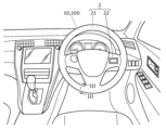
まず、図1~図3を参照しながら、本実施の形態に係る電極構造体10の使用例について説明する。図1は、実施の形態に係る電極構造体10の使用例を示す図である。図2は、実施の形態に係る電極構造体10が、ステアリングホイール2に取り付けられる前の状態を示す説明図である。図3は、実施の形態におけるステアリングホイール2の断面図である。図3は、ステアリングホイール2のリム21の軸方向断面を示しており、具体的には、図3は、図1におけるIII-III線を含む切断面を見た断面図である。図2では、ステアリングホイール2が中立位置にある場合の時計の3時の位置を「3h」と示し、6時の位置を「6h」と示し、9時の位置を「9h」と示し、12時の位置を「12h」と示している。これは以降の図において同様である。
(Example of use of electrode structure)
First, an example of use of the
また、図3では、リム21の前面側を「前面」と示し、背面側を「背面」と示している。リム21の前面側とは、リム21を側面視した場合の運転者側を向く半分領域であり、リム21の背面側とは、リム21を側面視した場合の運転者とは反対側を向く半分領域である。
In addition, in FIG. 3, the front side of the
本実施の形態における電極構造体10は、車載用のグリップセンサ100の一部として構成され、例えば車両1のステアリングホイール2に設けられている。電極構造体10は、運転者の手によるステアリングホイール2の把持を検出する静電容量式のセンサ電極(以下、センサ部ともいう。)である。
The
ここで、ステアリングホイール2は、リム21と、リム21の内周面に一体的に形成された略T字状のスポーク22とを有しており、リム21に対して電極構造体10が巻き付けられている。具体的には、図2に示すように、電極構造体10は、その長手方向の中心がリム21の上端部(12時の位置)に配置されるように、リム21に対して巻き付けられる。このため、電極構造体10の長手方向の両端部は、リム21の下端部(6時の位置)で、隣り合うように配置される。グリップセンサ100は、電極構造体10をセンサ部として備えるとともに、電極構造体10からの信号に基づいてリム21に対する運転者の把持を検出する制御回路3と、制御回路3と電極構造体10とを電気的に接続する複数のハーネス4とを備えている。
Here, the
図3に示すように、リム21は、軸方向断面視において円形の軸体が、平面視で円環状に形成された部位である。リム21には、当該リム21の芯材をなす金属製の芯金23が内在している。リム21には、軸方向断面において電極構造体10が接着層8を介して全周を覆っている。電極構造体10の外周面には、ウレタンまたは皮革からなるカバー体9が積層されている。
As shown in FIG. 3, the
電極構造体10では、車両1の運転者がステアリングホイール2のリム21を把持しているか否かに応じて静電容量が変化する。具体的には、電極構造体10は、運転者の手と電極構造体10との間の静電容量の変化を示す信号を制御回路3に出力する。この信号に基づいて、制御回路3は、運転者の手がリム21(厳密にはカバー体9の表面)に触れているか否かを検出する。
In the
図2では、ステアリングホイール2が中立位置である場合を示しているが、この状態では、リム21の下端部が、着座した運転者の下肢に対向する下肢対向部25となる。下肢対向部25は、ステアリングホイール2を平面視した場合、上下方向に沿う中心線C1に対し、左右のそれぞれで角度α内に収まる範囲である。角度αは、5度以上45度以下であれば好ましく、15度以上30度以下であればより好ましい。さらに、図3に示すように、リム21は、軸方向視において中心線C2よりも上側が運転者の下肢に対向せず、下側が運転者の下肢に対向する。この中心線C2は、リム21を平面視した場合の当該リムの中心を基準とした円に基づく。中心線C2は、断面視したリム21の前面側の頂点と、背面側の頂点とを結んだ線とも言える。つまり、下肢対向部25は、リム21の上記範囲内で、断面視における中心線C2よりも下方に位置する領域である。
2 shows the case where the
(実施の形態1)
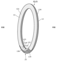
次に、実施の形態1に係る電極構造体10の構成について説明する。図4は、実施の形態1に係る電極構造体10を展開して示す平面図である。図5は、実施の形態1に係る電極構造体10が中立位置にあるリム21に巻き付けられた状態において、第一センサ電極12及び第二センサ電極13の位置関係を示す斜視図である。
(Embodiment 1)
Next, the configuration of the
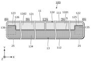
図4では、電極構造体10の長手方向をX軸方向とし、電極構造体10の幅方向をY軸方向とし、厚み方向をZ軸方向としている。X軸方向は、ステアリングホイール2を平面視した場合(図2参照)の周方向に対応し、Y軸方向は、ステアリングホイール2を軸方向視した場合の周方向(図3参照)に対応する。図4では、電極構造体10において、リム21に巻き付けられた際に表側となる主面が示されている。図4では、下肢対向部25の外形を二点鎖線で示している。なお、図4では、電極構造体10が展開されているために、下肢対向部25はX軸方向に二分割されている。図4及び図5では、第一センサ電極12を淡いドットハッチングで示し、第二センサ電極13を濃いドットハッチングで示している。第一センサ電極12と第二センサ電極13とは、隙間Sをあけて配置されている。隙間Sは、全長にわたって均等な線幅となっている。
In FIG. 4, the longitudinal direction of the
図4に示すように、電極構造体10は、基材11と、第一センサ電極12と、第二センサ電極13とを有している。基材11は、X軸方向に長尺なシート体である。具体的には、基材11は、弾性、柔軟性及び延性を有する材質によって形成された絶縁部材である。基材11は、例えば、ポリエチレン(PE)、ポリエチレンテレフタレート(PET)、ポリウレタン(PU)等の合成樹脂によって構成されたフォーム材である。基材11は、リム21の形状、及び、大きさに応じて形成される。なお、基材11は、延性を有する材質に限定されるものではなく、延性の小さい例えば不織布を用いてもよい。
As shown in FIG. 4, the
ここで、基材11において、Y軸方向の中心からY軸プラス方向の領域は、リム21の前面側に配置される第一領域111である。他方、基材11において、Y軸方向の中心からY軸マイナス方向の領域は、リム21の背面側に配置される第二領域112である。図4では、第一領域111と第二領域112との境界を一点鎖線で示している。上述したように、電極構造体10の長手方向(X軸方向)の両端部は、リム21の下端部(6時の位置)で、隣り合うように配置される。つまり、基材11は、当該基材11の長手方向の両端部が下肢対向部25で隣り合うように、リム21に巻き付けられている。巻き付けられた状態では、基材11の裏側の主面が、リム21上の接着層8に重なる。
Here, in the
第一センサ電極12は、第一領域111に配置された導電層である。具体的には、第一センサ電極12は、全体として第一領域111内に収められている。第一センサ電極12は、第一部121と、第二部122と、第三部123とを一体的に有している。
The
第一部121は、第一領域111内において下肢対向部25に対向しない部分に形成された平面視長方形状の部位である。第一部121は、下肢対向部25に対向しない部分の略全体を覆っている。
The
第二部122は、第一部121のX軸プラス方向の端部からX軸プラス方向に突出した平面視長方形状の部位である。第二部122は、第一突出部の一例である。第二部122は、第一部121のY軸プラス方向の半分領域から突出している。このため、第一センサ電極12において、X軸プラス方向の端部には、下肢対向部25に対応する部分に形成された平面視長方形状の切欠部125が設けられている。切欠部125は、第二部122とY軸方向で隣り合う第一切欠部の一例である。なお、第二部122のY軸方向の幅は、下肢と対向しなければ、第一部121のY軸方向の幅に対し、半分以上でもよいし、半分未満でもよい。
The
第三部123は、第一部121のX軸マイナス方向の端部からX軸マイナス方向に突出した平面視長方形状の部位である。第三部123は、第一突出部の一例である。第三部123は、第一部121のY軸プラス方向の半分領域から突出している。このため、第一センサ電極12において、X軸マイナス方向の端部には、下肢対向部25に対応する部分に形成された平面視長方形状の切欠部126が設けられている。切欠部126は、第三部123とY軸方向で隣り合う第一切欠部の一例である。各切欠部125、126によって、下肢対向部25には第一センサ電極12が配置されていない。なお、第三部123のY軸方向の幅は、下肢と対向しなければ、第一部121のY軸方向の幅に対し、半分以上でもよいし、半分未満でもよい。
The
第二センサ電極13は、第二領域112に配置された導電層である。この導電層も第一センサ電極12と同様に、例えば導電性を有するシートを基材11に貼付等により形成したものである。具体的には、第二センサ電極13は、主に第二領域112に配置されており、一部が第一領域111に配置されている。第二センサ電極13は、第四部134と、第五部135と、第六部136とを一体的に有している。
The
第四部134は、第二領域112の全体に形成された平面視長方形状の部位である。
The
第五部135は、第四部134のX軸プラス方向の端部からY軸プラス方向に突出し、切欠部125内に延出した平面視長方形状の部位である。第五部135は、延出部の一例である。第五部135は、切欠部125により露出された第一領域111を全体的に覆っている。
The
第六部136は、第四部134のX軸マイナス方向の端部からY軸プラス方向に突出し、切欠部126内に延出した平面視長方形状の部位である。第六部136は、延出部の一例である。第六部136は、切欠部126により露出された第一領域111を全体的に覆っている。
The
このように、下肢対向部25には、第二センサ電極13の第五部135及び第六部136が配置され、第一センサ電極12は配置されていない。このため、図5に示すように、リム21が中立位置にある場合、下肢対向部25には第二センサ電極13のみが配置されている。
In this way, the
ここで、第一センサ電極12、及び、第二センサ電極13を構成する導電層について説明する。導電層は例えば導電性を有するシート(導電性シート)を基材11に貼付等により形成したものである。特に導電層として、延性を有し、引っ張ることにより比抵抗が増加する導電性シートを用いている。このような導電性シートとしては、例えば導電ゴムシートのように引っ張ると薄くなり比抵抗が増すものが挙げられる。このような導電層とした理由は次の通りである。
Here, the conductive layers constituting the
図2で説明したように、電極構造体10はリム21に対して巻き付けられている。この際、電極構造体10は、図4におけるX軸方向の中心線部分(隙間Sの部分)がリム21を正面視したときの最外周に巻き付けられるので、電極構造体10の中心線部分が引っ張られた状態でリム21に巻き付けられる。その結果、基材11とともに、第一センサ電極12、及び、第二センサ電極13の中心線部分近傍に配される導電層は引っ張られることにより比抵抗が増す。一方、中心線部分からY軸方向に離れた基材11の端部の導電層は、ほとんど引っ張られることなくリム21に巻き付けられ、比抵抗はほとんど増加しない。したがって、リム21に巻き付けられた状態では、導電層はリム21の最外周近傍の比抵抗が大きく、リム21の内周近傍(図4のY軸プラス方向の基材11の端部、及び、Y軸マイナス方向の基材11の端部)に巻き付けられる導電層の比抵抗は、最外周近傍の比抵抗より小さくなる。
2, the
次に、例えば、図4において、運転者がステアリングホイール2の3hの部分を把持したとき、第一センサ電極12に着目すると、運転者の掌は第一センサ電極12を構成する導電層の中心線部分からY軸プラス方向の基材11の端部に跨って対向する。この時の第一センサ電極12の感度は、中心線部分の比抵抗が大きく、Y軸プラス方向の基材11の端部では比抵抗が小さいので、後者が支配的となる。
Next, for example, in FIG. 4, when the driver grips
一方、図4において、運転者がステアリングホイール2の5hに相当する部分を把持したとき、第一センサ電極12に着目すると、運転者の掌は第一突出部(第二部122)のみに対向する。この時の第一センサ電極12の感度は、比抵抗が小さい第一突出部、つまり、Y軸プラス方向の基材11の端部が支配的となる。
In FIG. 4, when the driver grips the part of the
これらのことから、第一センサ電極12における感度は、3h、及び、5hのいずれを把持してもY軸プラス方向の基材11の端部の感度が支配的となり、中心線部分の感度の影響は相対的に小さくなる。したがって、上記した導電層を用いることにより、第一突出部(第二部122及び第三部123)とその他の部分(第一部121)とで、把持位置による感度の変化を低減することができ、検知精度を高めることが可能である。
For these reasons, the sensitivity of the
(効果など)
以上のように本開示に係る電極構造体は、ステアリングホイール2のリム21に巻き付けられる電極構造体10であって、リム21の前面側に配置される第一領域111及びリム21の背面側に配置される第二領域112を有する基材11と、第一領域111に配置される第一センサ電極12と、第二領域112に配置される第二センサ電極13と、を備え、ステアリングホイール2が中立位置にある場合に、リム21において運転者の下肢に対向する下肢対向部25には、第二センサ電極13のみが配置されている。
(Effects, etc.)
As described above, the electrode structure of the present disclosure is an
これによれば、リム21の前面側である第一領域111に第一センサ電極12が配置され、リム21の背面側である第二領域112に第二センサ電極13が配置されているので、第一センサ電極12と第二センサ電極13との双方に運転者の手が接触した場合を、運転者がリムを把持したと検知(把持検知)することができる。つまり、第一センサ電極12と第二センサ電極13の一方のみに運転者の手が接触しただけでは把持検知されないので、把持検知の精度を高めることができる。
With this, the
さらに、下肢対向部25には、第二センサ電極13のみが配置されている。このため、下肢対向部25に運転者の下肢が接触したとしても、第一センサ電極12及び第二センサ電極13の双方には接触しない。つまり、下肢の接触を起因とした誤検知を抑制することができる。したがって、誤検知を抑制可能な電極構造体10を提供できる。
Furthermore, only the
また、第一センサ電極12は、下肢対向部25に対応する部分に形成された第一切欠部(切欠部125、126)と、リム21の軸方向断面における周方向で、切欠部125、126に隣り合う第一突出部(第二部122及び第三部123)とを有している。
The
これによれば、第一切欠部で不感領域を形成しつつ、第一突出部で検知領域を確保することができる。したがって、不感領域が必要以上に大型になることを抑制できる。 This allows the first protruding portion to secure a detection area while forming a dead area in the first notch. This prevents the dead area from becoming unnecessarily large.
また、第二センサ電極13は、第一切欠部内に延出した延出部(第五部135及び第六部136)を有してもよい。
The
これによれば、第二センサ電極13の延出部が、第一センサ電極12の第一切欠部内に延出しているので、下肢対向部25は、第二センサ電極13で覆われることになる。これにより、下肢対向部25に運転者の下肢が接触したとしても、第二センサ電極13のみに接触する。つまり、下肢の接触を起因とした誤検知を抑制することができる。
As a result, the extension of the
ところで、リム21に基材11を巻き付ける際には、センサ電極(第一センサ電極12お帯び第二センサ電極13)の有無で引っ張られ具合がばらつくが、第一切欠部内に延出部が配置されているので、そのばらつきを抑制でき、巻き付けの不均一性を抑制できる。
When wrapping the
また、基材11は、当該基材11の両端部が下肢対向部25で隣り合うように、リム21に巻き付けられている。
The
これによれば、基材11の両端部が下肢対向部25で隣り合っているので、ステアリングホイール2が中立位置にある場合に、基材11の両端部の境界を目立ちにくくすることができる。
As a result, since both ends of the
また、第一センサ電極12、及び、第二センサ電極13は、引っ張られることにより比抵抗が増加する導電性シートからなっている。
The
これによれば、下肢対向部25と、それ以外の部分とで、把持位置によるセンサ感度の変化を低減することができる。
This makes it possible to reduce the change in sensor sensitivity due to grip position between the lower
(実施の形態2)
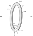
次に、実施の形態2に係る電極構造体10Aについて説明する。図6は、実施の形態2に係る電極構造体10Aを展開して示す平面図である。図7は、実施の形態2に係る電極構造体10Aが中立位置にあるリム21に巻き付けられた状態において、第一センサ電極12及び第二センサ電極13aの位置関係を示す斜視図である。図6は、図4に対応する図であり、図7は、図5に対応する図である。
(Embodiment 2)
Next, an
図6に示すように、実施の形態2に係る電極構造体10Aでは、第二センサ電極13aが実施の形態1に係る第二センサ電極13と異なっている。以降の説明において、実施の形態1と同等の部分については、同等の符号を付してその説明を省略する場合がある。
As shown in FIG. 6, in the
具体的には、第二センサ電極13aは、全体として第二領域112内に収められている。第二センサ電極13aは、第四部134aと、第五部135aと、第六部136aとを一体的に有している。
Specifically, the
第四部134aは、第二領域112内において下肢対向部25に対向しない部分に形成された平面視長方形状の部位である。第四部134aは、下肢対向部25に対向しない部分の略全体を覆っている。
The
第五部135aは、第四部134aのX軸プラス方向の端部からX軸プラス方向に突出した平面視長方形状の部位である。第五部135aは、第二突出部の一例である。第五部135aは、第四部134aのY軸マイナス方向の半分領域から突出している。このため、第二センサ電極13aにおいて、X軸プラス方向の端部には、下肢対向部25に対応する部分に形成された平面視長方形状の切欠部137aが設けられている。切欠部137aは、第五部135aとY軸方向で隣り合う第二切欠部の一例である。なお、第五部135aのY軸方向の幅は、下肢と対向しなければ、第四部134aのY軸方向の幅に対し、半分以上でもよいし、半分未満でもよい。
The
第六部136aは、第四部134aのX軸マイナス方向の端部からX軸マイナス方向に突出した平面視長方形状の部位である。第六部136aは、第二突出部の一例である。第六部136aは、第四部134aのY軸マイナス方向の半分領域から突出している。このため、第二センサ電極13aにおいて、X軸マイナス方向の端部には、下肢対向部25に対応する部分に形成された平面視長方形状の切欠部138aが設けられている。切欠部138aは、第六部136aとY軸方向で隣り合う第二切欠部の一例である。なお、第六部136aのY軸方向の幅は、下肢と対向しなければ、第四部134aのY軸方向の幅に対し、半分以上でもよいし、半分未満でもよい。
The
各切欠部137a、138aによって、下肢対向部25には第二センサ電極13aが配置されていない(図7参照)。つまり、実施の形態2では、下肢対向部25に、第一センサ電極12及び第二センサ電極13aの双方が配置されておらず基材11が露出している。したがって、下肢対向部25に運転者の下肢が接触したとしても、第一センサ電極12及び第二センサ電極13aの双方には接触しない。つまり、下肢の接触を起因とした誤検知を抑制することができる。
The
また、第一センサ電極12と、第二センサ電極13aとは、下肢対向部25に対応する箇所では第一長さL1で離間し、下肢対向部25以外に対応する箇所では第二長さL2で離間している。第一長さL1は、第二長さL2よりも長い。
The
このように、第一センサ電極12と第二センサ電極13aとは、第一長さL1または第二長さL2で離間しているので、これらが干渉することを抑制できる。さらに、下肢対向部25に対応する箇所では第一センサ電極12と第二センサ電極13aとが、第二長さL2よりも長い第一長さL1で離間しているので、不感領域を大きく確保できる。
In this way, the
また、第二センサ電極13aは、下肢対向部25に対応する部分に形成された第二切欠部(切欠部137a、138a)と、リム21の軸方向断面における周方向で、第二切欠部に隣り合う第二突出部(第五部135a及び第六部136a)とを有している。
The
これによれば、第二切欠部で不感領域を形成しつつ、第二突出部で検知領域を確保することができる。したがって、不感領域が必要以上に大型になることを抑制できる。 This allows the second cutout to form a dead zone while the second protruding portion ensures a detection zone. This prevents the dead zone from becoming unnecessarily large.
(実施の形態3)
次に、実施の形態3に係る電極構造体10Bについて説明する。図8は、実施の形態3に係る電極構造体10Bを展開して示す平面図である。図8は、図6に対応する図である。
(Embodiment 3)
Next, an
図8に示すように、実施の形態3に係る電極構造体10Bでは、第一センサ電極12b及び第二センサ電極13bが実施の形態2に係る第一センサ電極12及び第二センサ電極13aと異なっている。以降の説明において、実施の形態1、2と同等の部分については、同等の符号を付してその説明を省略する場合がある。
As shown in FIG. 8, in the
第一センサ電極12bの第二部122b及び第三部123bは、それぞれ先細る形状となっている。具体的には、第二部122bは、X軸方向と平行な部分と、X軸プラス方向に向かうにつれて、Y軸プラス方向に先細るようにX軸方向に対して傾斜した部分(傾斜部1221b)とを有している。第二部122bは、先端部が平面視長方形状に形成されている。このように、切欠部125bと第二部122bとの境界は、傾斜部1221bを含んでいる。同様に、第三部123bは、X軸方向と平行な部分と、X軸マイナス方向に向かうにつれて、Y軸プラス方向に先細るようにX軸方向に対して傾斜した部分(傾斜部1231b)とを有している。第三部123bは、先端部が平面視長方形状に形成されている。このように、切欠部126bと第三部123bとの境界は、傾斜部1231bを含んでいる。
The
第二センサ電極13bの第五部135b及び第六部136bは、それぞれ先細る形状となっている。具体的には、第五部135bは、X軸方向と平行な部分と、X軸プラス方向に向かうにつれて、Y軸マイナス方向に先細るようにX軸方向に対して傾斜した部分(傾斜部1351b)とを有している。第五部135bは、先端部が平面視長方形状に形成されている。このように、切欠部137bと第五部135bとの境界は、傾斜部1351bを含んでいる。第六部136bは、X軸方向と平行な部分と、X軸マイナス方向に向かうにつれて、Y軸マイナス方向に先細るようにX軸方向に対して傾斜した部分(傾斜部1361b)とを有している。第六部136bは、先端部が平面視長方形状に形成されている。このように、切欠部138bと第六部136bとの境界は、傾斜部1361bを含んでいる。
The
実施の形態3によれば、第一切欠部(切欠部125b、126b)と、第一突出部(第二部122b及び第三部123b)との境界は傾斜部1221b、1231bを含んでいる。
According to
これによれば、第一切欠部と第一突出部との境界に傾斜部1221b、1231bが含まれているので、検知領域である第一突出部が急峻に減少することを抑制できる。したがって、第一切欠部を起因とした感度低下を抑制できる。これは、第二センサ電極13bにおいても同様である。
As a result, the boundary between the first notch and the first protrusion includes the
なお、実施の形態3では、例えば、第二部122bのY軸マイナス方向の辺の一部が傾斜部1221bとなっている場合を例示したが、当該辺の全体が傾斜部となっていてもよい。これは、第三部、第五部、第六部において同様である。
In the third embodiment, for example, a part of the side of the
また、実施の形態3と同様に、実施の形態1の図4においても、第二部122と第三部123のY軸マイナス方向の辺の一部が傾斜していてもよい。この場合、第五部135が第二部122と対応するように傾斜し、第六部136が第三部123と対応するように傾斜していてもよい。
As in the third embodiment, in FIG. 4 of the first embodiment, a portion of the side of the
(実施の形態4)
次に、実施の形態4に係る電極構造体10Cについて説明する。図9は、実施の形態4に係る電極構造体10Cを展開して示す平面図である。図9は、図4に対応する図である。
(Embodiment 4)
Next, an
図9に示すように、実施の形態4に係る電極構造体10Cでは、第二センサ電極13cが実施の形態1に係る第二センサ電極13と異なっている。以降の説明において、実施の形態1と同等の部分については、同等の符号を付してその説明を省略する場合がある。
As shown in FIG. 9, in the
第二センサ電極13cは、全体として長方形状であり、第二領域112の略全体を覆っている。第二センサ電極13cにおいて、X軸プラス方向及びY軸プラス方向の角部と、X軸マイナス方向及びY軸プラス方向の角部とは、下肢対向部25内に配置されている。つまり、下肢対向部25には、第二センサ電極13cのみが配置されている。このため、下肢対向部25に運転者の下肢が接触したとしても、第一センサ電極12及び第二センサ電極13cの双方には接触しない。つまり、下肢の接触を起因とした誤検知を抑制することができる。
The
(実施の形態5)
次に、実施の形態5に係る電極構造体10Dについて説明する。図10は、実施の形態5に係る電極構造体10Dを展開して示す平面図である。図10は、図4に対応する図である。
(Embodiment 5)
Next, an
図10に示すように、実施の形態5に係る電極構造体10Dでは、第一センサ電極12dがX軸方向で二分割されている点で、実施の形態1に係る第一センサ電極12と異なっている。以降の説明において、実施の形態1と同等の部分については、同等の符号を付してその説明を省略する場合がある。
As shown in FIG. 10, the
第一センサ電極12dは、X軸方向の中央部(12時の位置)で分割されており、X軸プラス方向の第一右電極12d1と、X軸マイナス方向の第一左電極12d2とを有している。第一右電極12d1と第一左電極12d2は、それぞれ独立して制御回路3に電気的に接続されている。制御回路3は、第一右電極12d1からの信号と、第一左電極12d2からの信号とに基づいて、運転者の手がリム21の右半分を把持したか、左半分を把持したかを検出することが可能である。
The
なお、図11は、実施の形態5の他の例に係る電極構造体10Eを展開して示す平面図である。図11は、図6に対応する図である。つまり、図11に示す電極構造体10Eは、実施の形態2に係る電極構造体10Aの第一センサ電極12をX軸方向で二分割している。この構成においても、図10の構成と同様に、運転者の手がリム21の右半分を把持したか、左半分を把持したかを検出することが可能である。
Note that FIG. 11 is a plan view showing an expanded
(実施の形態6)
次に、実施の形態6に係る電極構造体10Fについて説明する。図12は、実施の形態6に係る電極構造体10Fを展開して示す平面図である。図12は、図10に対応する図である。
(Embodiment 6)
Next, an
図12に示すように、実施の形態6に係る電極構造体10Fでは、第二センサ電極13fがX軸方向で2分割されている点で、実施の形態5に係る第二センサ電極13と異なっている。以降の説明において、実施の形態5と同等の部分については、同等の符号を付してその説明を省略する場合がある。
As shown in FIG. 12, the
第二センサ電極13fは、X軸方向の中央部(12時の位置)で分割されており、X軸プラス方向の第二右電極13f1と、X軸マイナス方向の第二左電極13f2とを有している。第二右電極13f1と第二左電極13f2は、それぞれ独立して制御回路3に電気的に接続されている。制御回路3は、第一右電極12d1からの信号と、第一左電極12d2からの信号と、第二右電極13f1からの信号と、第二左電極13f2からの信号とに基づいて、運転者が正しくリム21に触れていないことを判断できる。具体的には、第一右電極12d1からの信号と、第二左電極13f2からの信号との両者のみが、手の接触を検出できる信号である場合、あるいは、第一左電極12d2からの信号と、第二右電極13f1からの信号との両者のみが、手の接触を検出できる信号である場合には、制御回路3は、正しくリム21に触れていないと判断し、警告を報知する。
The
なお、図13は、実施の形態6の他の例に係る電極構造体10Gを展開して示す平面図である。図13は、図11に対応する図である。つまり、図13に示す電極構造体10Fは、実施の形態5の他の例に係る電極構造体10Eの第一センサ電極12をX軸方向で二分割している。この構成においても、図12の構成と同様に、制御回路3は、正しくリム21に触れていない場合を判断し、警告を報知する。
Note that FIG. 13 is a plan view showing an
(実施の形態7)
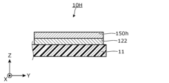
次に、実施の形態7に係る電極構造体10Hについて説明する。図14は、実施の形態7に係る電極構造体10Fの部分断面図である。図14は、電極構造体10Hの第二部122を含む部分の断面図である。
(Seventh embodiment)
Next, a description will be given of an
図14に示すように、実施の形態7に係る電極構造体10Hでは、第二部122に重なる第一導電層150hが設けられてる点で、実施の形態1に係る電極構造体10と異なる。以降の説明において、実施の形態1と同等の部分については、同等の符号を付してその説明を省略する場合がある。
As shown in FIG. 14, the
第一導電層150hは、第二部122の全体に対して重なっている。第一導電層150hは、導電テープ、導電性接着剤などから構成されている。このように、第一突出部の一例である第二部122に第一導電層150hが重なっているので、第一導電層150hにより感度を高めることができる。その結果、運転者がステアリングホイール2を把持したときの手と対向する面積が第一部121に比べ小さい第二部122であっても、第一部121との感度差を抑制することができ、したがって、検知精度をより高めることが可能である。なお、他の第一突出部に重なる第一導電層、第二突出部に重なる第一導電層が設けられていてもよい。
The first
(実施の形態8)
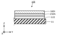
次に、実施の形態8に係る電極構造体10Iについて説明する。図15は、実施の形態8に係る電極構造体10Iの部分断面図である。図15は、電極構造体10Iの第二部122を含む部分の断面図である。図15は、図14に対応する図である。
(Embodiment 8)
Next, an electrode structure 10I according to an eighth embodiment will be described. Fig. 15 is a partial cross-sectional view of the electrode structure 10I according to the eighth embodiment. Fig. 15 is a cross-sectional view of a portion including a
図15に示すように、実施の形態8に係る電極構造体10Iでは、第一導電層150hに重なる第二導電層160iが設けられてる点で、実施の形態7に係る電極構造体10Hと異なる。以降の説明において、実施の形態7と同等の部分については、同等の符号を付してその説明を省略する場合がある。
As shown in FIG. 15, the electrode structure 10I according to
第二導電層160iは、第一導電層150hの全体に対して重なっている。具体的には、第一導電層150hとして両面に粘着層を有する導電テープを用い、第二導電層160iが第一導電層150hに貼付される構成を有する。第二導電層160iは、第二部122(第一センサ電極12)よりも導電率が異なっているのであればその形態は如何様でもよいが、特に、第二導電層160iは、第二部122よりも導電率が高いとよい。このような第二導電層160iが第一導電層150hに対して重なっているので、第一導電層150hのみが第二部122と重なっている図14の構成に比べ、第二導電層160iにより感度を高めることが可能である。そのため、第一部121との感度差を、実施の形態7の構成に比べ、さらに抑制することができ、したがって、検知精度をより高めることが可能である。なお、他の第一突出部に重なる第一導電層、第二突出部に重なる第一導電層に対しても、第二導電層が重なっていてもよい。
The second
[その他]
以上、本開示に係る電極構造体について、実施の形態に基づいて説明したが、本開示は、この実施の形態に限定されるものではない。本開示の趣旨を逸脱しない限り、当業者が思いつく各種変形を本実施の形態に施したものや、異なる実施の形態における構成要素を組み合わせて構築される形態も、本開示の一つまたは複数の態様の範囲内に含まれてもよい。
[others]
Although the electrode structure according to the present disclosure has been described based on the embodiment, the present disclosure is not limited to this embodiment. As long as it does not deviate from the gist of the present disclosure, various modifications conceived by a person skilled in the art to this embodiment and forms constructed by combining components in different embodiments may also be included within the scope of one or more aspects of the present disclosure.
[付記]
以上の実施の形態等の記載により、下記の技術が開示される。
[Additional Notes]
The above description of the embodiments and the like discloses the following techniques.
(技術1)
ステアリングホイールのリムに巻き付けられる電極構造体であって、
前記リムの前面側に配置される第一領域及び前記リムの背面側に配置される第二領域を有する基材と、
前記第一領域に配置される第一センサ電極と、
前記第二領域に配置される第二センサ電極と、を備え、
前記ステアリングホイールが中立位置にある場合に、前記リムにおいて運転者の下肢に対向する下肢対向部には、前記第一センサ電極及び前記第二センサ電極のそれぞれが配置されていない、または、前記第一センサ電極及び前記第二センサ電極の一方のみが配置されている、
電極構造体。
(Technique 1)
An electrode structure wrapped around a steering wheel rim, comprising:
a substrate having a first region disposed on a front side of the rim and a second region disposed on a rear side of the rim;
a first sensor electrode disposed in the first region;
a second sensor electrode disposed in the second region;
When the steering wheel is in a neutral position, neither the first sensor electrode nor the second sensor electrode is disposed on a lower leg facing portion of the rim that faces the lower leg of a driver, or only one of the first sensor electrode and the second sensor electrode is disposed on the lower leg facing portion.
Electrode structure.
(技術2)
前記第一センサ電極は、前記下肢対向部に対応する部分に形成された第一切欠部と、前記リムの軸方向断面における周方向で、前記第一切欠部に隣り合う第一突出部とを有する、
技術1に記載の電極構造体。
(Technique 2)
The first sensor electrode has a first notch formed in a portion corresponding to the lower leg opposing portion, and a first protruding portion adjacent to the first notch in a circumferential direction in an axial cross section of the rim.
The electrode structure according to the first aspect.
(技術3)
前記第一突出部に対して重なる第一導電層を有する、
技術2に記載の電極構造体。
(Technique 3)
a first conductive layer overlying the first protruding portion;
The electrode structure according to the second aspect of the present invention.
(技術4)
前記第一導電層に対して重なる第二導電層を有する、
技術3に記載の電極構造体。
(Technique 4)
a second conductive layer overlying the first conductive layer;
The electrode structure according to
(技術5)
前記第一切欠部と、前記第一突出部との境界は傾斜部を含む、
技術2~4のいずれかひとつに記載の電極構造体。
(Technique 5)
The boundary between the first notch and the first protruding portion includes an inclined portion.
The electrode structure according to any one of
(技術6)
前記第一センサ電極と、前記第二センサ電極とは、前記下肢対向部に対応する箇所では第一長さで離間し、前記下肢対向部以外に対応する箇所では第二長さで離間し、
前記第一長さは、前記第二長さよりも長い、
技術1~5のいずれかひとつに記載の電極構造体。
(Technique 6)
The first sensor electrode and the second sensor electrode are spaced apart by a first length at a location corresponding to the lower limb facing portion, and are spaced apart by a second length at a location other than the lower limb facing portion,
The first length is greater than the second length.
The electrode structure according to any one of techniques 1 to 5.
(技術7)
前記第二センサ電極は、前記下肢対向部に対応する部分に形成された第二切欠部と、前記リムの軸方向断面における周方向で、前記第二切欠部に隣り合う第二突出部とを有する、
技術1~6のいずれかひとつに記載の電極構造体。
(Technique 7)
The second sensor electrode has a second notch portion formed in a portion corresponding to the lower leg opposing portion, and a second protruding portion adjacent to the second notch portion in a circumferential direction in an axial cross section of the rim.
The electrode structure according to any one of techniques 1 to 6.
(技術8)
前記第二センサ電極は、前記第一切欠部内に延出した延出部を有する、
技術2~5のいずれかひとつに記載の電極構造体。
(Technique 8)
The second sensor electrode has an extension portion extending into the first notch.
The electrode structure according to any one of
(技術9)
前記基材は、当該基材の両端部が前記下肢対向部で隣り合うように、前記リムに巻き付けられている、
技術1~8のいずれかひとつに記載の電極構造体。
(Technique 9)
The base material is wrapped around the rim so that both ends of the base material are adjacent to each other at the lower leg facing portion.
The electrode structure according to any one of techniques 1 to 8.
(技術10)
前記第一センサ電極、及び、前記第二センサ電極は、引っ張られることにより比抵抗が増加する導電性シートからなる、
技術1~9のいずれかひとつに記載の電極構造体。
(Technique 10)
The first sensor electrode and the second sensor electrode are made of a conductive sheet whose resistivity increases when stretched.
The electrode structure according to any one of techniques 1 to 9.
本開示に係る電極構造体は、移動体のステアリングホイール等に適用可能である。 The electrode structure disclosed herein can be applied to steering wheels of moving objects, etc.
1 車両
2 ステアリングホイール
3 制御回路
4 ハーネス
8 接着層
9 カバー体
10、10A、10B、10C、10D、10E、10F、10G、10H、10I 電極構造体
11 基材
12、12b、12d 第一センサ電極
12d1 第一右電極
12d2 第一左電極
13、13a、13b、13c、13f 第二センサ電極
13f1 第二右電極
13f2 第二左電極
21 リム
22 スポーク
23 芯金
25 下肢対向部
100 グリップセンサ
111 第一領域
112 第二領域
121 第一部
122、122b 第二部(第一突出部)
123、123b 第三部(第一突出部)
125、125b、126、126b 切欠部(第一切欠部)
134、134a 第四部
135 第五部(延出部)
135a、135b 第五部(第二突出部)
136 第六部(延出部)
136a、136b 第六部(第二突出部)
137a、137b、138、138b 切欠部(第二切欠部)
150h 第一導電層
160i 第二導電層
1221b、1231b、1351b、1361b 傾斜部
C1、C2 中心線
L1 第一長さ
L2 第二長さ
S 隙間
α 角度
1
123, 123b Third part (first protrusion)
125, 125b, 126, 126b Notch portion (first notch portion)
134, 134a
135a, 135b Fifth part (second protruding part)
136 Part 6 (Extending part)
136a, 136b Sixth part (second protrusion)
137a, 137b, 138, 138b: cutout portion (second cutout portion)
150h First
Claims (10)
前記リムの前面側に配置される第一領域及び前記リムの背面側に配置される第二領域を有する基材と、
前記第一領域に配置される第一センサ電極と、
前記第二領域に配置される第二センサ電極と、を備え、
前記ステアリングホイールが中立位置にある場合に、前記リムにおいて運転者の下肢に対向する下肢対向部には、前記第一センサ電極及び前記第二センサ電極のそれぞれが配置されていない、または、前記第一センサ電極及び前記第二センサ電極の一方のみが配置されている、
電極構造体。 An electrode structure that is wrapped around a steering wheel rim, comprising:
a substrate having a first region disposed on a front side of the rim and a second region disposed on a rear side of the rim;
a first sensor electrode disposed in the first region;
a second sensor electrode disposed in the second region;
When the steering wheel is in a neutral position, neither the first sensor electrode nor the second sensor electrode is disposed on a lower leg facing portion of the rim that faces the lower leg of a driver, or only one of the first sensor electrode and the second sensor electrode is disposed on the lower leg facing portion.
Electrode structure.
請求項1に記載の電極構造体。 The first sensor electrode has a first notch formed in a portion corresponding to the lower leg opposing portion, and a first protruding portion adjacent to the first notch in a circumferential direction in an axial cross section of the rim.
The electrode structure of claim 1 .
請求項2に記載の電極構造体。 a first conductive layer overlying the first protruding portion;
The electrode structure according to claim 2 .
請求項3に記載の電極構造体。 a second conductive layer overlying the first conductive layer;
The electrode structure according to claim 3 .
請求項2~4のいずれか一項に記載の電極構造体。 The boundary between the first notch and the first protruding portion includes an inclined portion.
The electrode structure according to any one of claims 2 to 4.
前記第一長さは、前記第二長さよりも長い、
請求項1~4のいずれか一項に記載の電極構造体。 The first sensor electrode and the second sensor electrode are spaced apart by a first length at a location corresponding to the lower limb facing portion, and are spaced apart by a second length at a location other than the lower limb facing portion,
The first length is greater than the second length.
The electrode structure according to any one of claims 1 to 4.
請求項1~4のいずれか一項に記載の電極構造体。 The second sensor electrode has a second notch portion formed in a portion corresponding to the lower leg opposing portion, and a second protruding portion adjacent to the second notch portion in a circumferential direction in an axial cross section of the rim.
The electrode structure according to any one of claims 1 to 4.
請求項2~4のいずれか一項に記載の電極構造体。 The second sensor electrode has an extension portion extending into the first notch.
The electrode structure according to any one of claims 2 to 4.
請求項1~4のいずれか一項に記載の電極構造体。 The base material is wrapped around the rim so that both ends of the base material are adjacent to each other at the lower leg facing portion.
The electrode structure according to any one of claims 1 to 4.
請求項1~4のいずれか一項に記載の電極構造体。 The first sensor electrode and the second sensor electrode are made of a conductive sheet whose resistivity increases when stretched.
The electrode structure according to any one of claims 1 to 4.
Priority Applications (2)
| Application Number | Priority Date | Filing Date | Title |
|---|---|---|---|
| JP2023066610A JP2024152425A (en) | 2023-04-14 | 2023-04-14 | Electrode Structure |
| US18/624,995 US20240344906A1 (en) | 2023-04-14 | 2024-04-02 | Electrode structure |
Applications Claiming Priority (1)
| Application Number | Priority Date | Filing Date | Title |
|---|---|---|---|
| JP2023066610A JP2024152425A (en) | 2023-04-14 | 2023-04-14 | Electrode Structure |
Publications (1)
| Publication Number | Publication Date |
|---|---|
| JP2024152425A true JP2024152425A (en) | 2024-10-25 |
Family
ID=93017318
Family Applications (1)
| Application Number | Title | Priority Date | Filing Date |
|---|---|---|---|
| JP2023066610A Pending JP2024152425A (en) | 2023-04-14 | 2023-04-14 | Electrode Structure |
Country Status (2)
| Country | Link |
|---|---|
| US (1) | US20240344906A1 (en) |
| JP (1) | JP2024152425A (en) |
Families Citing this family (1)
| Publication number | Priority date | Publication date | Assignee | Title |
|---|---|---|---|---|
| CN118683551A (en) * | 2023-03-24 | 2024-09-24 | 本田技研工业株式会社 | Driving assistance devices |
Family Cites Families (3)
| Publication number | Priority date | Publication date | Assignee | Title |
|---|---|---|---|---|
| WO2018079096A1 (en) * | 2016-10-28 | 2018-05-03 | 本田技研工業株式会社 | Steering wheel unit |
| JP2023055420A (en) * | 2021-10-06 | 2023-04-18 | 株式会社東海理化電機製作所 | steering |
| CN120188248A (en) * | 2023-03-24 | 2025-06-20 | 住友理工株式会社 | Sensor sheet and method for manufacturing sensor sheet |
-
2023
- 2023-04-14 JP JP2023066610A patent/JP2024152425A/en active Pending
-
2024
- 2024-04-02 US US18/624,995 patent/US20240344906A1/en active Pending
Also Published As
| Publication number | Publication date |
|---|---|
| US20240344906A1 (en) | 2024-10-17 |
Similar Documents
| Publication | Publication Date | Title |
|---|---|---|
| JP6719165B2 (en) | Vehicle steering wheel | |
| CN105074862B (en) | Electrostatic capacitance sensor and steering wheel | |
| JP2018203061A (en) | Occupant information detection sensor for steering wheel | |
| JP2019002712A (en) | Electrostatic sensor | |
| JP6642703B2 (en) | Manufacturing method of steering wheel | |
| JP6449832B2 (en) | Steering wheel unit | |
| US10807628B2 (en) | Steering apparatus | |
| JP2019213663A (en) | Steering device | |
| JP2024152425A (en) | Electrode Structure | |
| US20240369384A1 (en) | Electrode structure and grip sensor | |
| JP2018067423A (en) | Grip sensor | |
| US20230104284A1 (en) | Steering apparatus | |
| KR20210120069A (en) | Detection device for vehicle steering wheel | |
| JP2016190570A (en) | Grip detection device and capacitance sensor | |
| JP7741605B2 (en) | Electrode structure and grip sensor | |
| JP6351801B2 (en) | Gripping state detection sensor | |
| JP7481192B2 (en) | Steering grip sensor and steering | |
| US20230242171A1 (en) | Steering wheel | |
| JP2020082790A (en) | Steering unit | |
| CN223031051U (en) | Steering wheel | |
| CN115876230A (en) | Detection mechanism | |
| JP2024152401A (en) | Electrode Structure | |
| US12054189B2 (en) | Steering wheel | |
| JP2019095229A (en) | Capacitance sensor and steering | |
| JP2019091578A (en) | Capacitance sensor and steering |
Legal Events
| Date | Code | Title | Description |
|---|---|---|---|
| A711 | Notification of change in applicant |
Free format text: JAPANESE INTERMEDIATE CODE: A711 Effective date: 20240304 |
|
| A621 | Written request for application examination |
Free format text: JAPANESE INTERMEDIATE CODE: A621 Effective date: 20260108 |