JP2024531237A - 駆動機構、ブレーキ装置用圧力発生器 - Google Patents
駆動機構、ブレーキ装置用圧力発生器 Download PDFInfo
- Publication number
- JP2024531237A JP2024531237A JP2024508666A JP2024508666A JP2024531237A JP 2024531237 A JP2024531237 A JP 2024531237A JP 2024508666 A JP2024508666 A JP 2024508666A JP 2024508666 A JP2024508666 A JP 2024508666A JP 2024531237 A JP2024531237 A JP 2024531237A
- Authority
- JP
- Japan
- Prior art keywords
- circuit board
- printed circuit
- drive mechanism
- shielding plate
- housing
- Prior art date
- Legal status (The legal status is an assumption and is not a legal conclusion. Google has not performed a legal analysis and makes no representation as to the accuracy of the status listed.)
- Granted
Links
Images
Classifications
-
- H—ELECTRICITY
- H02—GENERATION; CONVERSION OR DISTRIBUTION OF ELECTRIC POWER
- H02K—DYNAMO-ELECTRIC MACHINES
- H02K5/00—Casings; Enclosures; Supports
- H02K5/04—Casings or enclosures characterised by the shape, form or construction thereof
- H02K5/16—Means for supporting bearings, e.g. insulating supports or means for fitting bearings in the bearing-shields
- H02K5/173—Means for supporting bearings, e.g. insulating supports or means for fitting bearings in the bearing-shields using bearings with rolling contact, e.g. ball bearings
- H02K5/1732—Means for supporting bearings, e.g. insulating supports or means for fitting bearings in the bearing-shields using bearings with rolling contact, e.g. ball bearings radially supporting the rotary shaft at both ends of the rotor
-
- H—ELECTRICITY
- H02—GENERATION; CONVERSION OR DISTRIBUTION OF ELECTRIC POWER
- H02K—DYNAMO-ELECTRIC MACHINES
- H02K11/00—Structural association of dynamo-electric machines with electric components or with devices for shielding, monitoring or protection
- H02K11/01—Structural association of dynamo-electric machines with electric components or with devices for shielding, monitoring or protection for shielding from electromagnetic fields, i.e. structural association with shields
- H02K11/014—Shields associated with stationary parts, e.g. stator cores
- H02K11/0141—Shields associated with casings, enclosures or brackets
-
- H—ELECTRICITY
- H02—GENERATION; CONVERSION OR DISTRIBUTION OF ELECTRIC POWER
- H02K—DYNAMO-ELECTRIC MACHINES
- H02K11/00—Structural association of dynamo-electric machines with electric components or with devices for shielding, monitoring or protection
- H02K11/20—Structural association of dynamo-electric machines with electric components or with devices for shielding, monitoring or protection for measuring, monitoring, testing, protecting or switching
- H02K11/21—Devices for sensing speed or position, or actuated thereby
- H02K11/225—Detecting coils
-
- H—ELECTRICITY
- H02—GENERATION; CONVERSION OR DISTRIBUTION OF ELECTRIC POWER
- H02K—DYNAMO-ELECTRIC MACHINES
- H02K11/00—Structural association of dynamo-electric machines with electric components or with devices for shielding, monitoring or protection
- H02K11/30—Structural association with control circuits or drive circuits
- H02K11/33—Drive circuits, e.g. power electronics
-
- H—ELECTRICITY
- H02—GENERATION; CONVERSION OR DISTRIBUTION OF ELECTRIC POWER
- H02K—DYNAMO-ELECTRIC MACHINES
- H02K11/00—Structural association of dynamo-electric machines with electric components or with devices for shielding, monitoring or protection
- H02K11/40—Structural association with grounding devices
-
- B—PERFORMING OPERATIONS; TRANSPORTING
- B60—VEHICLES IN GENERAL
- B60T—VEHICLE BRAKE CONTROL SYSTEMS OR PARTS THEREOF; BRAKE CONTROL SYSTEMS OR PARTS THEREOF, IN GENERAL; ARRANGEMENT OF BRAKING ELEMENTS ON VEHICLES IN GENERAL; PORTABLE DEVICES FOR PREVENTING UNWANTED MOVEMENT OF VEHICLES; VEHICLE MODIFICATIONS TO FACILITATE COOLING OF BRAKES
- B60T13/00—Transmitting braking action from initiating means to ultimate brake actuator with power assistance or drive; Brake systems incorporating such transmitting means, e.g. air-pressure brake systems
- B60T13/74—Transmitting braking action from initiating means to ultimate brake actuator with power assistance or drive; Brake systems incorporating such transmitting means, e.g. air-pressure brake systems with electrical assistance or drive
- B60T13/745—Transmitting braking action from initiating means to ultimate brake actuator with power assistance or drive; Brake systems incorporating such transmitting means, e.g. air-pressure brake systems with electrical assistance or drive acting on a hydraulic system, e.g. a master cylinder
-
- H—ELECTRICITY
- H02—GENERATION; CONVERSION OR DISTRIBUTION OF ELECTRIC POWER
- H02K—DYNAMO-ELECTRIC MACHINES
- H02K2211/00—Specific aspects not provided for in the other groups of this subclass relating to measuring or protective devices or electric components
- H02K2211/03—Machines characterised by circuit boards, e.g. pcb
-
- H—ELECTRICITY
- H02—GENERATION; CONVERSION OR DISTRIBUTION OF ELECTRIC POWER
- H02K—DYNAMO-ELECTRIC MACHINES
- H02K5/00—Casings; Enclosures; Supports
- H02K5/04—Casings or enclosures characterised by the shape, form or construction thereof
- H02K5/16—Means for supporting bearings, e.g. insulating supports or means for fitting bearings in the bearing-shields
- H02K5/173—Means for supporting bearings, e.g. insulating supports or means for fitting bearings in the bearing-shields using bearings with rolling contact, e.g. ball bearings
Landscapes
- Engineering & Computer Science (AREA)
- Power Engineering (AREA)
- Microelectronics & Electronic Packaging (AREA)
- Physics & Mathematics (AREA)
- Electromagnetism (AREA)
- Transportation (AREA)
- Mechanical Engineering (AREA)
- Motor Or Generator Frames (AREA)
Abstract

【選択図】 図3
Description
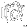
2 駆動機構
3 駆動機構のハウジング
4 電気機械
5 ポンプ機構
8 制御デバイス
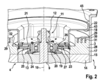
9 駆動軸
10 駆動軸の回転軸線
13 電気機械のロータ
14 電気機械のステータ
18 ベアリングシールド
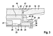
23 センサユニット
24 プリント回路基板
29,30,31 モータ相供給導線
32 担持要素
33 担持要素の基礎体
37 遮蔽板
38 遮蔽板の第1の部分
39 遮蔽板の第2の部分
42 遮蔽板の曲げ連結部
Claims (12)
- ハウジング(3)内に配置される電気機械(4)であって、前記電気機械(4)のロータ(13)が前記ハウジング(3)内に回転可能に支持される駆動軸(9)に相対回転不能に配置されている前記電気機械(4)と、前記ロータ(13)の回転位置を検知するために形成されているセンサユニット(23)であって、前記センサユニット(23)が少なくとも1つのセンサ素子を備えたプリント回路基板(24)を有し、前記プリント回路基板(24)がリングディスク状に形成されて、前記駆動軸(9)の回転軸線(10)に対し同軸に配置されている前記センサユニット(23)とを備える駆動機構において、前記プリント回路基板(24)が前記ハウジング(3)内に配置されていることと、前記駆動機構(2)が、前記プリント回路基板(24)を少なくとも部分的に半径方向に取り囲む遮蔽板(37)を有していることとを特徴とする駆動機構。
- 前記遮蔽板(37)が前記プリント回路基板(24)を半径方向において全周にわたって取り囲んでいることを特徴とする、請求項1に記載の駆動機構。
- 前記遮蔽板(37)が前記ハウジング(3)に固定され、特に形状拘束的結合によって固定されていることを特徴とする、請求項1または2に記載の駆動機構。
- 前記遮蔽板(37)が少なくとも1つの曲げ連結部(42)を有し、前記曲げ連結部(42)によって前記ハウジング(3)に固定されていることを特徴とする、請求項3に記載の駆動機構。
- 前記遮蔽板(37)が前記ハウジング(3)のベアリングシールド(18)に固定されていることを特徴とする、請求項3または4に記載の駆動機構。
- 前記電気機械(4)が、特に多相のモータ巻線を備えたステータ(14)を有し、前記モータ巻線が、少なくとも1つの導電性のモータ相供給導線(29,30,31)によって、電気エネルギー蓄積器と電気結合されており、または、電気結合可能であり、前記遮蔽板(37)が、半径方向において、一方では前記プリント回路基板(24)と、他方では前記モータ相供給導線(29,30,31)との間に配置されていることを特徴とする、請求項1~5のいずれか一項に記載の駆動機構。
- 前記駆動機構(3)が、前記ハウジング(3)に固定されて前記プリント回路基板(24)を担持する担持要素(32)を有していることと、前記担持要素(32)が前記遮蔽板(37)を有していることとを特徴とする、請求項1~6のいずれか一項に記載の駆動機構。
- 前記担持要素(32)がプラスチックから製造される基礎体(33)を有していることと、前記遮蔽板(37)が前記基礎体(33)によって前記プリント回路基板(24)から電気的に切り離されていることとを特徴とする、請求項7に記載の駆動機構。
- 前記担持要素(32)が前記遮蔽板(37)によって前記ハウジング(3)に固定されていることを特徴とする、請求項7または8に記載の駆動機構。
- 前記遮蔽板(37)が、少なくとも実質的に軸線方向に延びている第1の部分(38)と、少なくとも実質的に半径方向に延びている第2の部分(39)とを有し、前記第1の部分(38)が前記プリント回路基板(24)を少なくとも部分的に半径方向に取り囲み、前記第2の部分(39)が前記プリント回路基板(24)を少なくとも部分的に覆っていることを特徴とする、請求項1~9のいずれか一項に記載の駆動機構。
- ポンプ機構(5)と、前記ポンプ機構(5)を操作するための駆動機構(2)と、前記駆動機構(2)を制御するための制御デバイス(8)とを備えたブレーキ装置用圧力発生器において、前記駆動機構(2)が請求項1~10のいずれか一項に従って形成されていることを特徴とするブレーキ装置用圧力発生器。
- 前記遮蔽板(37)が前記制御デバイス(8)の電気アース接続部と電気結合されていることを特徴とする、請求項11に記載の圧力発生器。
Applications Claiming Priority (3)
| Application Number | Priority Date | Filing Date | Title |
|---|---|---|---|
| DE102021209125.3A DE102021209125A1 (de) | 2021-08-19 | 2021-08-19 | Antriebseinrichtung, Druckerzeuger für eine Bremsanlage |
| DE102021209125.3 | 2021-08-19 | ||
| PCT/EP2022/072207 WO2023020868A1 (de) | 2021-08-19 | 2022-08-08 | Antriebseinrichtung, druckerzeuger für eine bremsanlage |
Publications (2)
| Publication Number | Publication Date |
|---|---|
| JP2024531237A true JP2024531237A (ja) | 2024-08-29 |
| JP7759714B2 JP7759714B2 (ja) | 2025-10-24 |
Family
ID=83188875
Family Applications (1)
| Application Number | Title | Priority Date | Filing Date |
|---|---|---|---|
| JP2024508666A Active JP7759714B2 (ja) | 2021-08-19 | 2022-08-08 | 駆動機構、ブレーキ装置用圧力発生器 |
Country Status (7)
| Country | Link |
|---|---|
| US (1) | US20240250584A1 (ja) |
| EP (1) | EP4388645A1 (ja) |
| JP (1) | JP7759714B2 (ja) |
| KR (1) | KR20240046565A (ja) |
| CN (1) | CN117813751A (ja) |
| DE (1) | DE102021209125A1 (ja) |
| WO (1) | WO2023020868A1 (ja) |
Citations (5)
| Publication number | Priority date | Publication date | Assignee | Title |
|---|---|---|---|---|
| JPH03111153U (ja) * | 1990-02-26 | 1991-11-14 | ||
| JP2018042332A (ja) * | 2016-09-06 | 2018-03-15 | 日本電産サンキョー株式会社 | モータ |
| JP2019009885A (ja) * | 2017-06-23 | 2019-01-17 | 日本電産サンキョー株式会社 | モータ |
| JP2020031466A (ja) * | 2018-08-21 | 2020-02-27 | 株式会社デンソー | モータ装置 |
| US20200191616A1 (en) * | 2018-12-12 | 2020-06-18 | Mando Corporation | Actuator assembly having rotary sensor responsive to rotation of magnet |
Family Cites Families (7)
| Publication number | Priority date | Publication date | Assignee | Title |
|---|---|---|---|---|
| JP5007581B2 (ja) * | 2007-03-01 | 2012-08-22 | 日本電産株式会社 | モータ |
| JP4457156B2 (ja) * | 2008-03-31 | 2010-04-28 | 山洋電気株式会社 | 電磁ブレーキ付きモータ |
| JP5320380B2 (ja) | 2010-12-20 | 2013-10-23 | 本田技研工業株式会社 | 車両用ブレーキ装置 |
| WO2018147012A1 (ja) * | 2017-02-07 | 2018-08-16 | 日本電産株式会社 | モータ |
| DE102018108716A1 (de) * | 2018-04-12 | 2019-10-17 | Lenze Drives Gmbh | Elektromotor mit integriertem Drehgeber |
| CN208939772U (zh) | 2018-10-25 | 2019-06-04 | 比亚迪股份有限公司 | 一种旋转变压器及具有其的电机 |
| EP3705851A1 (de) * | 2019-03-06 | 2020-09-09 | Siemens Aktiengesellschaft | Haltevorrichtung für einen drehgeber |
-
2021
- 2021-08-19 DE DE102021209125.3A patent/DE102021209125A1/de active Pending
-
2022
- 2022-08-08 CN CN202280055565.2A patent/CN117813751A/zh active Pending
- 2022-08-08 WO PCT/EP2022/072207 patent/WO2023020868A1/de not_active Ceased
- 2022-08-08 US US18/293,228 patent/US20240250584A1/en active Pending
- 2022-08-08 JP JP2024508666A patent/JP7759714B2/ja active Active
- 2022-08-08 KR KR1020247008577A patent/KR20240046565A/ko active Pending
- 2022-08-08 EP EP22764362.4A patent/EP4388645A1/de active Pending
Patent Citations (5)
| Publication number | Priority date | Publication date | Assignee | Title |
|---|---|---|---|---|
| JPH03111153U (ja) * | 1990-02-26 | 1991-11-14 | ||
| JP2018042332A (ja) * | 2016-09-06 | 2018-03-15 | 日本電産サンキョー株式会社 | モータ |
| JP2019009885A (ja) * | 2017-06-23 | 2019-01-17 | 日本電産サンキョー株式会社 | モータ |
| JP2020031466A (ja) * | 2018-08-21 | 2020-02-27 | 株式会社デンソー | モータ装置 |
| US20200191616A1 (en) * | 2018-12-12 | 2020-06-18 | Mando Corporation | Actuator assembly having rotary sensor responsive to rotation of magnet |
Also Published As
| Publication number | Publication date |
|---|---|
| EP4388645A1 (de) | 2024-06-26 |
| WO2023020868A1 (de) | 2023-02-23 |
| KR20240046565A (ko) | 2024-04-09 |
| US20240250584A1 (en) | 2024-07-25 |
| CN117813751A (zh) | 2024-04-02 |
| DE102021209125A1 (de) | 2023-02-23 |
| JP7759714B2 (ja) | 2025-10-24 |
Similar Documents
| Publication | Publication Date | Title |
|---|---|---|
| US7268451B2 (en) | Motor resolver assembly and method of measuring speed and position of a motor rotor | |
| JP4628460B2 (ja) | 回転電機、及びその製造方法 | |
| EP4009499B1 (en) | Motor, and motor-driven steering apparatus having same | |
| US6998813B2 (en) | Device for generation of a signal dependent on rotational speed for an electric motor, in particular for an electronically-commutated DC motor | |
| EP1286451B1 (en) | Dynamoelectric machine | |
| EP3249787A1 (en) | Drive device | |
| US20130088108A1 (en) | Electric motor | |
| JP2019077436A (ja) | 電子式にスリップ制御可能な車両ブレーキ装置の駆動装置、特に液圧装置 | |
| MX2014009313A (es) | Disposicion para determinar la posicion angular del eje de un motor electrico, y motor de limpiaparabrisas con una disposicion para determinar la posicion angular. | |
| KR20190012501A (ko) | 모터 | |
| US6107704A (en) | Microelectric motor | |
| JP2008182834A (ja) | 電動モータのシール構造 | |
| JP7759714B2 (ja) | 駆動機構、ブレーキ装置用圧力発生器 | |
| US12494700B2 (en) | Drive device for a braking device of a motor vehicle | |
| JP7745082B2 (ja) | 電気機械のロータの回転位置を検出するセンサ装置、駆動装置、ブレーキ設備のための圧力発生器 | |
| CN1307773C (zh) | 旋转电机 | |
| CN114175463B (zh) | 旋转电机的定子以及旋转电机 | |
| JP5155632B2 (ja) | ブラシレスモータ | |
| JP6305312B2 (ja) | 駆動装置 | |
| CN210839222U (zh) | 电动机和排水阀驱动装置 | |
| JP6447264B2 (ja) | 回転電機及びモータ装置 | |
| CN109586479B (zh) | 马达和电动助力转向装置 | |
| JP6149693B2 (ja) | 回転電機 | |
| WO2021131199A1 (ja) | モータ | |
| JP2026022225A (ja) | レゾルバの電磁遮蔽構造 |
Legal Events
| Date | Code | Title | Description |
|---|---|---|---|
| A521 | Request for written amendment filed |
Free format text: JAPANESE INTERMEDIATE CODE: A523 Effective date: 20240409 |
|
| A621 | Written request for application examination |
Free format text: JAPANESE INTERMEDIATE CODE: A621 Effective date: 20240409 |
|
| A131 | Notification of reasons for refusal |
Free format text: JAPANESE INTERMEDIATE CODE: A131 Effective date: 20250219 |
|
| A977 | Report on retrieval |
Free format text: JAPANESE INTERMEDIATE CODE: A971007 Effective date: 20250219 |
|
| A601 | Written request for extension of time |
Free format text: JAPANESE INTERMEDIATE CODE: A601 Effective date: 20250506 |
|
| A601 | Written request for extension of time |
Free format text: JAPANESE INTERMEDIATE CODE: A601 Effective date: 20250718 |
|
| A521 | Request for written amendment filed |
Free format text: JAPANESE INTERMEDIATE CODE: A523 Effective date: 20250805 |
|
| TRDD | Decision of grant or rejection written | ||
| A01 | Written decision to grant a patent or to grant a registration (utility model) |
Free format text: JAPANESE INTERMEDIATE CODE: A01 Effective date: 20250929 |
|
| A61 | First payment of annual fees (during grant procedure) |
Free format text: JAPANESE INTERMEDIATE CODE: A61 Effective date: 20251013 |
|
| R150 | Certificate of patent or registration of utility model |
Ref document number: 7759714 Country of ref document: JP Free format text: JAPANESE INTERMEDIATE CODE: R150 |