JP2025008043A - Exterior parts, protective devices and wire harnesses - Google Patents

Exterior parts, protective devices and wire harnesses Download PDF

Info

Publication number
JP2025008043A
JP2025008043A JP2023109883A JP2023109883A JP2025008043A JP 2025008043 A JP2025008043 A JP 2025008043A JP 2023109883 A JP2023109883 A JP 2023109883A JP 2023109883 A JP2023109883 A JP 2023109883A JP 2025008043 A JP2025008043 A JP 2025008043A
Authority
JP
Japan
Prior art keywords
locking
exterior member
divided
locking piece
ridge
Prior art date
Legal status (The legal status is an assumption and is not a legal conclusion. Google has not performed a legal analysis and makes no representation as to the accuracy of the status listed.)
Pending
Application number
JP2023109883A
Other languages
Japanese (ja)
Inventor
大地 福嶋
Daichi Fukushima
竜也 青木
Tatsuya Aoki
Current Assignee (The listed assignees may be inaccurate. Google has not performed a legal analysis and makes no representation or warranty as to the accuracy of the list.)
Sumitomo Wiring Systems Ltd
AutoNetworks Technologies Ltd
Sumitomo Electric Industries Ltd
Original Assignee
Sumitomo Wiring Systems Ltd
AutoNetworks Technologies Ltd
Sumitomo Electric Industries Ltd
Priority date (The priority date is an assumption and is not a legal conclusion. Google has not performed a legal analysis and makes no representation as to the accuracy of the date listed.)
Filing date
Publication date
Application filed by Sumitomo Wiring Systems Ltd, AutoNetworks Technologies Ltd, Sumitomo Electric Industries Ltd filed Critical Sumitomo Wiring Systems Ltd
Priority to JP2023109883A priority Critical patent/JP2025008043A/en
Priority to PCT/JP2024/022018 priority patent/WO2025009382A1/en
Publication of JP2025008043A publication Critical patent/JP2025008043A/en
Pending legal-status Critical Current

Links

Images

Classifications

    • FMECHANICAL ENGINEERING; LIGHTING; HEATING; WEAPONS; BLASTING
    • F16ENGINEERING ELEMENTS AND UNITS; GENERAL MEASURES FOR PRODUCING AND MAINTAINING EFFECTIVE FUNCTIONING OF MACHINES OR INSTALLATIONS; THERMAL INSULATION IN GENERAL
    • F16LPIPES; JOINTS OR FITTINGS FOR PIPES; SUPPORTS FOR PIPES, CABLES OR PROTECTIVE TUBING; MEANS FOR THERMAL INSULATION IN GENERAL
    • F16L57/00Protection of pipes or objects of similar shape against external or internal damage or wear
    • HELECTRICITY
    • H02GENERATION; CONVERSION OR DISTRIBUTION OF ELECTRIC POWER
    • H02GINSTALLATION OF ELECTRIC CABLES OR LINES, OR OF COMBINED OPTICAL AND ELECTRIC CABLES OR LINES
    • H02G3/00Installations of electric cables or lines or protective tubing therefor in or on buildings, equivalent structures or vehicles
    • H02G3/02Details
    • H02G3/04Protective tubing or conduits, e.g. cable ladders or cable troughs
    • HELECTRICITY
    • H02GENERATION; CONVERSION OR DISTRIBUTION OF ELECTRIC POWER
    • H02GINSTALLATION OF ELECTRIC CABLES OR LINES, OR OF COMBINED OPTICAL AND ELECTRIC CABLES OR LINES
    • H02G3/00Installations of electric cables or lines or protective tubing therefor in or on buildings, equivalent structures or vehicles
    • H02G3/02Details
    • H02G3/06Joints for connecting lengths of protective tubing or channels, to each other or to casings, e.g. to distribution boxes; Ensuring electrical continuity in the joint

Landscapes

  • Engineering & Computer Science (AREA)
  • General Engineering & Computer Science (AREA)
  • Architecture (AREA)
  • Civil Engineering (AREA)
  • Structural Engineering (AREA)
  • Mechanical Engineering (AREA)
  • Details Of Indoor Wiring (AREA)
  • Protection Of Pipes Against Damage, Friction, And Corrosion (AREA)

Abstract

To provide a technique capable of suppressing enlargement of a size in an exterior member including a lock structure.SOLUTION: An exterior member 10 comprises: a first division member 20 including a lock part 30; and a second division member 20 including a locked part 40 which is locked to the lock part 30. Each of the first division member 20 and the second division member 20 includes a division cylinder part 21, and protruding line parts 22 and 26 which protrude from an inner surface or an outer surface of the division cylinder part 21 and are fitted to an annular groove of a target member. The lock part 30 has lock pieces 32 and 36 which protrude from peripheral ends of the protruding line parts 22 and 26 in a circumferential direction. The locked part 40 has lock receiving parts 42 and 46 which are formed in a portion where the protruding line parts 22 and 26 are partially recessed, and are locked with the lock pieces 32 and 36.SELECTED DRAWING: Figure 1

Description

本開示は、外装部材、保護装置及びワイヤーハーネスに関する。 This disclosure relates to exterior components, protective devices, and wire harnesses.

特許文献1は、コルゲートチューブを保持するワイヤーハーネス保持具を開示している。当該ワイヤーハーネス保持具では、一対の半円環状部材がロック部及び被ロック部によってロックされて、円環状部材とされる。 Patent Document 1 discloses a wire harness holder that holds a corrugated tube. In this wire harness holder, a pair of semicircular ring members are locked by a locking portion and a locked portion to form a ring member.

特開2020-191720号公報JP 2020-191720 A

特許文献1に記載のワイヤーハーネス保持具では、ロック部及び被ロック部は半円環状部材の外側に張り出すように別途設けられているため、ワイヤーハーネス保持具のサイズが大きくなる要因となっていた。 In the wire harness holder described in Patent Document 1, the locking portion and the locked portion are provided separately so as to protrude outward from the semicircular ring member, which causes the wire harness holder to become large in size.

そこで、ロック構造を含む外装部材において、サイズの大型化を抑制できる技術を提供することを目的とする。 Therefore, the objective is to provide a technology that can prevent the size of exterior components that include a locking structure from increasing.

本開示の外装部材は、配線に外装されると共に、環状溝が設けられた対象部材に位置決めされる外装部材であって、ロック部を含む第1分割部材と、前記ロック部にロックする被ロック部を含む第2分割部材と、を備え、前記第1分割部材及び前記第2分割部材のそれぞれは、分割筒部と、前記分割筒部の内面又は外面から突出して前記環状溝に嵌る凸条部とを含み、前記ロック部は、前記凸条部の周端から周方向に突出する係止片を有し、前記被ロック部は、前記凸条部の一部が凹んだ部分に形成されて前記係止片と係止する係止受部を有する、外装部材である。 The exterior member of the present disclosure is an exterior member that is fitted to a wiring and is positioned on a target member having an annular groove, and includes a first divided member including a locking portion and a second divided member including a locked portion that locks to the locking portion, and each of the first divided member and the second divided member includes a divided tubular portion and a protruding ridge portion that protrudes from the inner or outer surface of the divided tubular portion and fits into the annular groove, the locking portion has a locking piece that protrudes in the circumferential direction from the peripheral end of the protruding ridge portion, and the locked portion has a locking receiving portion that is formed in a portion where the protruding ridge portion is recessed and that locks with the locking piece.

本開示によれば、ロック構造を含む外装部材において、サイズの大型化を抑制できる。 According to the present disclosure, it is possible to prevent the exterior member, including the locking structure, from becoming too large in size.

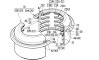
図1は実施形態1にかかる外装部材を示す分解斜視図である。FIG. 1 is an exploded perspective view showing an exterior member according to a first embodiment. 図2は実施形態1にかかる外装部材を示す分解平面図である。FIG. 2 is an exploded plan view showing the exterior member according to the first embodiment. 図3は実施形態1にかかる外装部材を示す分解側面図である。FIG. 3 is an exploded side view showing the exterior member according to the first embodiment. 図4は分割部材及び対象部材を示す正面図である。FIG. 4 is a front view showing the divided member and the target member. 図5は図3のV-V線に沿った断面図である。FIG. 5 is a cross-sectional view taken along line VV in FIG. 図6は図3のVI-VI線に沿った断面図である。FIG. 6 is a cross-sectional view taken along line VI-VI in FIG. 図7は外装部材が適用されたワイヤーハーネスを示す説明図である。FIG. 7 is an explanatory diagram showing a wire harness to which an exterior member is applied. 図8は外装部材が適用されたワイヤーハーネスを示す説明図である。FIG. 8 is an explanatory diagram showing a wire harness to which an exterior member is applied. 図9は図8のIX-IX線に沿った断面図である。FIG. 9 is a cross-sectional view taken along line IX-IX in FIG. 図10は外装部材の第1変形例を示す分解平面図である。FIG. 10 is an exploded plan view showing a first modified example of the exterior member. 図11は外装部材の第2変形例を示す分解平面図である。FIG. 11 is an exploded plan view showing a second modified example of the exterior member. 図12は外装部材の第3変形例を示す分解斜視図である。FIG. 12 is an exploded perspective view showing a third modified example of the exterior member. 図13は外装部材の第4変形例を示す分解斜視図である。FIG. 13 is an exploded perspective view showing a fourth modified example of the exterior member. 図14は第4変形例にかかる外装部材の断面図である。FIG. 14 is a cross-sectional view of an exterior member according to a fourth modified example. 図15は外装部材の第5変形例を示す分解斜視図である。FIG. 15 is an exploded perspective view showing a fifth modified example of the exterior member. 図16は図15のXVI-XVI線に沿った断面図である。FIG. 16 is a cross-sectional view taken along line XVI-XVI in FIG.

[本開示の実施形態の説明]
最初に本開示の実施態様を列記して説明する。
[Description of the embodiments of the present disclosure]
First, the embodiments of the present disclosure will be listed and described.

本開示の外装部材は、次の通りである。 The exterior components of this disclosure are as follows:

(1)配線に外装されると共に、環状溝が設けられた対象部材に位置決めされる外装部材であって、ロック部を含む第1分割部材と、前記ロック部にロックする被ロック部を含む第2分割部材と、を備え、前記第1分割部材及び前記第2分割部材のそれぞれは、分割筒部と、前記分割筒部の内面又は外面から突出して前記環状溝に嵌る凸条部とを含み、前記ロック部は、前記凸条部の周端から周方向に突出する係止片を有し、前記被ロック部は、前記凸条部の一部が凹んだ部分に形成されて前記係止片と係止する係止受部を有する、外装部材である。 (1) An exterior member that is fitted to a wiring and positioned on a target member having an annular groove, the exterior member includes a first divided member including a locking portion and a second divided member including a locked portion that locks to the locking portion, and each of the first divided member and the second divided member includes a divided tubular portion and a protruding ridge portion that protrudes from the inner or outer surface of the divided tubular portion and fits into the annular groove, the locking portion has a locking piece that protrudes in the circumferential direction from the peripheral end of the protruding ridge portion, and the locked portion has a locking receiving portion that is formed in a portion where the protruding ridge portion is recessed and that locks with the locking piece.

(1)の外装部材によると、環状溝に嵌るために凸とされた凸条部を用いて係止片及び係止受部が設けられることで、外装部材において、ロック部及び被ロック部の部分が別に凸となりにくい。これにより、ロック構造を含む外装部材において、ロック構造が設けられることによるサイズの大型化を抑制できる。 According to the exterior member of (1), the locking piece and the locking receiving part are provided using a convex rib part that is convex to fit into the annular groove, so that the locking part and the locked part are unlikely to be separately convex in the exterior member. This makes it possible to prevent the size of the exterior member including the locking structure from increasing due to the provision of the locking structure.

(2)(1)の外装部材において、前記凸条部として、前記分割筒部の前記内面に内側凸条部が設けられ、前記係止片として、前記内側凸条部の周端から周方向に突出する内側係止片が設けられ、前記係止受部として、前記内側凸条部の一部が凹んだ部分に形成されて前記内側係止片と係止する内側係止受部が設けられていてもよい。内側凸条部を用いて内側係止片及び内側係止受部が設けられることで、外装部材において、ロック部及び被ロック部の部分が別に凸となりにくい。これにより、ロック構造を含む外装部材において、ロック構造が設けられることによるサイズの大型化を抑制できる。 (2) In the exterior member of (1), the convex rib portion may be an inner rib portion provided on the inner surface of the split tube portion, the locking piece may be an inner locking piece protruding in the circumferential direction from the peripheral end of the inner rib portion, and the locking receiving portion may be an inner locking receiving portion formed in a partially recessed portion of the inner rib portion and locking with the inner locking piece. By providing the inner locking piece and the inner locking receiving portion using the inner rib portion, the locking portion and the locked portion of the exterior member are less likely to be separately convex. This makes it possible to prevent the size of the exterior member including the locking structure from increasing due to the provision of the locking structure.

(3)(2)の外装部材において、前記第1分割部材及び前記第2分割部材のそれぞれは、前記分割筒部の前記外面に前記凸条部が設けられていなくてもよい。分割筒部の外面に凸条部が設けられないことにより、外装部材において、サイズの大型化を抑制できる。 (3) In the exterior member of (2), the first divided member and the second divided member may not have the ridge portion provided on the outer surface of the divided tubular portion. By not providing the ridge portion on the outer surface of the divided tubular portion, it is possible to prevent the exterior member from becoming large in size.

(4)(2)の外装部材において、前記凸条部として、前記分割筒部の前記外面に外側凸条部がさらに設けられ、前記外側凸条部には、前記係止片及び前記係止受部は設けられていなくてもよい。外側凸条部には、係止片及び係止受部が設けられていないことにより、外装部材の構造を簡略化できる。 (4) In the exterior member of (2), an outer ridge portion may be further provided on the outer surface of the split tube portion as the ridge portion, and the outer ridge portion may not be provided with the locking piece and the locking receiving portion. Since the outer ridge portion does not have a locking piece and a locking receiving portion, the structure of the exterior member can be simplified.

(5)(1)の外装部材において、前記凸条部として、前記分割筒部の前記内面に内側凸条部が設けられていると共に前記分割筒部の前記外面に外側凸条部が設けられ、前記係止片として、前記外側凸条部の周端から周方向に突出する外側係止片が設けられ、前記係止受部として、前記外側凸条部の一部が凹んだ部分に形成されて前記外側係止片と係止する外側係止受部が設けられていてもよい。外側凸条部を用いて外側係止片及び外側係止受部が設けられることで、外装部材において、ロック部及び被ロック部の部分が別に凸となりにくい。これにより、ロック構造を含む外装部材において、ロック構造が設けられることによるサイズの大型化を抑制できる。 (5) In the exterior member of (1), the convex rib portion may be an inner convex rib portion provided on the inner surface of the split tubular portion and an outer convex rib portion provided on the outer surface of the split tubular portion, the locking piece may be an outer locking piece protruding in the circumferential direction from the peripheral end of the outer convex rib portion, and the locking receiving portion may be an outer locking receiving portion formed in a partially recessed portion of the outer convex rib portion and locking with the outer locking piece. By providing the outer locking piece and the outer locking receiving portion using the outer convex rib portion, the locking portion and the locked portion of the exterior member are less likely to be separately convex. This makes it possible to prevent the size of the exterior member including the locking structure from increasing due to the provision of the locking structure.

(6)(5)の外装部材において、前記係止片として、前記内側凸条部の周端から周方向に突出する内側係止片がさらに設けられ、前記係止受部として、前記内側凸条部の一部が凹んだ部分に形成されて前記内側係止片と係止する内側係止受部がさらに設けられていてもよい。これにより、内側凸条部を用いたロック構造と、外側凸条部を用いたロック構造とが設けられることによって、外装部材に2種類のロック構造が設けられる。これにより、第1分割部材と第2分割部材とのロック強度が増す。 (6) In the exterior member of (5), the locking piece may further include an inner locking piece that protrudes in the circumferential direction from the peripheral end of the inner ridge portion, and the locking receiving portion may further include an inner locking receiving portion that is formed in a partially recessed portion of the inner ridge portion and engages with the inner locking piece. In this way, two types of locking structures are provided in the exterior member by providing a locking structure using the inner ridge portion and a locking structure using the outer ridge portion. This increases the locking strength between the first and second divided members.

(7)(5)又は(6)の外装部材において、前記内側凸条部には、前記係止片及び前記係止受部は設けられていなくてもよい。内側凸条部には、係止片及び係止受部は設けられていないことにより、外装部材の構造を簡略化できる。 (7) In the exterior member of (5) or (6), the inner ridge portion may not be provided with the locking piece and the locking receiving portion. By not providing the locking piece and the locking receiving portion on the inner ridge portion, the structure of the exterior member can be simplified.

(8)(1)から(7)のいずれか1つの外装部材において、前記第1分割部材と前記第2分割部材とは互いに同一の形状を有してもよい。これにより、第1分割部材と第2分割部材とを共通の部品とすることができることによって、部品種類数の増加を抑制できる。 (8) In any one of the exterior members (1) to (7), the first divided member and the second divided member may have the same shape. This allows the first divided member and the second divided member to be a common part, thereby suppressing an increase in the number of part types.

(9)(1)から(8)のいずれか1つの外装部材において、前記外側凸条部は、前記内側凸条部による凹凸形状が形成された部分の外面に設けられていてもよい。これにより、内側凸条部及び外側凸条部が設けられる場合でも、外装部材の軸方向に沿った長さが長くなることを抑制できる。 (9) In any one of the exterior members (1) to (8), the outer ridge portion may be provided on the outer surface of the portion in which the uneven shape is formed by the inner ridge portion. This makes it possible to prevent the length of the exterior member along the axial direction from becoming long even when the inner ridge portion and the outer ridge portion are provided.

(10)また、本開示の保護装置は、(1)から(7)のいずれか1つの外装部材と、前記内側凸条部によって前記外装部材に中心軸回りに回転不能に保持されたコルゲートチューブと、前記外側凸条部によって前記外装部材を回転可能に保持する回転支持部材と、を備える、保護装置である。 (10) The protective device of the present disclosure is a protective device that includes an exterior member selected from any one of (1) to (7), a corrugated tube that is held by the inner ridge portion to the exterior member so as not to rotate around the central axis, and a rotation support member that holds the exterior member rotatably by the outer ridge portion.

(11)また、本開示のワイヤーハーネスは、(10)の保護装置と、前記保護装置に通された配線と、を備える、ワイヤーハーネスである。 (11) The wire harness of the present disclosure is a wire harness including the protective device of (10) and wiring passed through the protective device.

[本開示の実施形態の詳細]
本開示の外装部材の具体例を、以下に図面を参照しつつ説明する。なお、本開示はこれらの例示に限定されるものではなく、特許請求の範囲によって示され、特許請求の範囲と均等の意味及び範囲内でのすべての変更が含まれることが意図される。
[Details of the embodiment of the present disclosure]
Specific examples of the exterior member of the present disclosure will be described below with reference to the drawings. Note that the present disclosure is not limited to these examples, but is defined by the claims, and is intended to include all modifications within the meaning and scope of the claims.

[実施形態1]
以下、実施形態1にかかる外装部材について説明する。図1は実施形態1にかかる外装部材10を示す分解斜視図である。図2は実施形態1にかかる外装部材10を示す分解平面図である。図3は実施形態1にかかる外装部材10を示す分解側面図である。図4は分割部材20及び対象部材を示す正面図である。図5は図3のV-V線に沿った断面図である。図6は図3のVI-VI線に沿った断面図である。
[Embodiment 1]
The exterior member according to the first embodiment will be described below. Fig. 1 is an exploded perspective view showing the exterior member 10 according to the first embodiment. Fig. 2 is an exploded plan view showing the exterior member 10 according to the first embodiment. Fig. 3 is an exploded side view showing the exterior member 10 according to the first embodiment. Fig. 4 is a front view showing the divided member 20 and the target member. Fig. 5 is a cross-sectional view taken along line V-V in Fig. 3. Fig. 6 is a cross-sectional view taken along line VI-VI in Fig. 3.

図4に示すように、外装部材10は、配線80に外装される。外装部材10は、環状溝が設けられた対象部材に位置決めされる。対象部材は、例えば、コルゲートチューブ50又は回転支持部材60などである。図4に示す例では、対象部材として、コルゲートチューブ50及び回転支持部材60の両方が設けられている。ここで、コルゲートチューブ50は、環状凸部51と環状凹部52とが軸方向に交互に連続する形状を有する。配線80はコルゲートチューブ50に通される。配線80が通されたコルゲートチューブ50を外装部材10が覆う。外装部材10は、コルゲートチューブ50付の配線80に外装される。コルゲートチューブ50において、環状凹部52が環状溝に相当する。回転支持部材60は、保護筒部61を備える。保護筒部61には内面に環状溝63が形成された軸受部62が設けられる。軸受部62に外装部材10が回転可能に支持される。 As shown in FIG. 4, the exterior member 10 is fitted to the wiring 80. The exterior member 10 is positioned on a target member having an annular groove. The target member is, for example, a corrugated tube 50 or a rotating support member 60. In the example shown in FIG. 4, both the corrugated tube 50 and the rotating support member 60 are provided as target members. Here, the corrugated tube 50 has a shape in which annular convex portions 51 and annular concave portions 52 are alternately arranged in the axial direction. The wiring 80 is passed through the corrugated tube 50. The exterior member 10 covers the corrugated tube 50 through which the wiring 80 is passed. The exterior member 10 is fitted to the wiring 80 with the corrugated tube 50. In the corrugated tube 50, the annular concave portion 52 corresponds to the annular groove. The rotating support member 60 includes a protective tube portion 61. The protective tube portion 61 includes a bearing portion 62 having an annular groove 63 formed on its inner surface. The exterior member 10 is rotatably supported by the bearing portion 62.

外装部材10は、ロック部30を含む第1分割部材20Aと、ロック部30にロックする被ロック部40を含む第2分割部材20Bとを備える。第1分割部材20Aと第2分割部材20Bとが合わさった外装部材10は筒形状を有する。本開示において、周方向、径方向及び軸方向は、筒形状の外装部材10の周方向、径方向及び軸方向に対応するものとする。第1分割部材20Aと第2分割部材20Bとにおける分割の割合は特に限定されるものではなく、適宜設定可能である。本実施形態では、第1分割部材20Aと第2分割部材20Bとは半々に分割されている。 The exterior member 10 comprises a first divided member 20A including a locking portion 30, and a second divided member 20B including a locked portion 40 that locks to the locking portion 30. The exterior member 10 formed by combining the first divided member 20A and the second divided member 20B has a cylindrical shape. In this disclosure, the circumferential direction, radial direction, and axial direction correspond to the circumferential direction, radial direction, and axial direction of the cylindrical exterior member 10. The ratio of division between the first divided member 20A and the second divided member 20B is not particularly limited and can be set appropriately. In this embodiment, the first divided member 20A and the second divided member 20B are divided in half.

本実施形態では、第1分割部材20Aと第2分割部材20Bとのそれぞれは、ロック部30と被ロック部40とを含む。本実施形態では、第1分割部材20Aと第2分割部材20Bとは互いに同一の形状を有する。換言すると、外装部材10は、同一の形状を有する一対の分割部材20を備える。一対の分割部材20のうちの一方が第1分割部材20Aであり、他方が第2分割部材20Bである。以下では、第1分割部材20Aと第2分割部材20Bとについて特に区別する必要がない場合、単に分割部材20とする。 In this embodiment, each of the first divided member 20A and the second divided member 20B includes a locking portion 30 and a locked portion 40. In this embodiment, the first divided member 20A and the second divided member 20B have the same shape. In other words, the exterior member 10 includes a pair of divided members 20 having the same shape. One of the pair of divided members 20 is the first divided member 20A, and the other is the second divided member 20B. Hereinafter, when there is no particular need to distinguish between the first divided member 20A and the second divided member 20B, they will simply be referred to as divided members 20.

各分割部材20は、分割筒部21と、分割筒部21の内面又は外面から突出する凸条部とを含む。凸条部は対象部材の環状溝に嵌る部分である。ロック部30は、凸条部の周端から周方向に突出する係止片を有する。被ロック部40は、凸条部の一部が凹んだ部分に形成されて係止片と係止する係止受部を有する。各分割部材20は、例えば、樹脂製の射出成形品である。 Each divided member 20 includes a divided cylindrical portion 21 and a convex portion protruding from the inner or outer surface of the divided cylindrical portion 21. The convex portion is a portion that fits into the annular groove of the target member. The locking portion 30 has a locking piece that protrudes in the circumferential direction from the peripheral end of the convex portion. The locked portion 40 has a locking receiving portion that is formed in a recessed portion of the convex portion and locks with the locking piece. Each divided member 20 is, for example, an injection-molded product made of resin.

分割筒部21は、半筒状(ここでは半筒状)に形成されている。一対の分割筒部21が合わさって円筒状の筒部となる。筒部内にコルゲートチューブ50が通される。分割筒部21とされることによって、各分割部材20がコルゲートチューブ50に対して側方から被せられて、外装部材10とされる。分割筒部21の直径及び軸方向の長さ寸法は、特に限定されるものではなく、適宜設定可能である。分割筒部21の直径は、例えば、対象のコルゲートチューブ50の直径と同程度とされてもよい。コルゲートチューブ50の1組の環状凸部51及び環状凹部52を1周期とすると、分割筒部21の軸方向の長さ寸法は、例えば、コルゲートチューブ50の複数周期分(例えば3周期から9周期分)とされてもよい。 The split tube portion 21 is formed in a semi-cylindrical shape (here, semi-cylindrical). A pair of split tube portions 21 are joined together to form a cylindrical tube portion. The corrugated tube 50 is passed through the tube portion. By forming the split tube portion 21, each split member 20 is placed on the corrugated tube 50 from the side to form the exterior member 10. The diameter and axial length dimension of the split tube portion 21 are not particularly limited and can be set appropriately. The diameter of the split tube portion 21 may be, for example, approximately the same as the diameter of the target corrugated tube 50. If one set of annular convex portion 51 and annular concave portion 52 of the corrugated tube 50 is one period, the axial length dimension of the split tube portion 21 may be, for example, multiple periods of the corrugated tube 50 (for example, 3 to 9 periods).

ここでは、凸条部として、分割筒部21の内面に突出する内側凸条部22と、分割筒部21の外面に突出する外側凸条部26とが設けられている。内側凸条部22は、例えば、コルゲートチューブ50の環状凹部52に嵌る。コルゲートチューブ50において、環状凹部52が環状溝である。外側凸条部26は、例えば、回転支持部材60の環状溝63に嵌る。もっとも、凸条部として、内側凸条部22と外側凸条部26との両方が設けられることは必須の構成ではない。凸条部として、内側凸条部22と外側凸条部26とのうち内側凸条部22のみが設けられてもよいし、外側凸条部26のみが設けられてもよい。 Here, the convex rib portion includes an inner convex rib portion 22 that protrudes from the inner surface of the split tubular portion 21, and an outer convex rib portion 26 that protrudes from the outer surface of the split tubular portion 21. The inner convex rib portion 22 fits, for example, into an annular recess 52 of the corrugated tube 50. In the corrugated tube 50, the annular recess 52 is an annular groove. The outer convex rib portion 26 fits, for example, into an annular groove 63 of the rotation support member 60. However, it is not essential that both the inner convex rib portion 22 and the outer convex rib portion 26 are provided as the convex rib portion. Of the inner convex rib portion 22 and the outer convex rib portion 26, only the inner convex rib portion 22 may be provided as the convex rib portion, or only the outer convex rib portion 26 may be provided.

ここでは、内側凸条部22として、内側凸条部22A、22B、22Cが設けられている。分割筒部21の軸方向に沿って、分割筒部21の中間部に内側凸条部22Aが設けられ、分割筒部21の一端に内側凸条部22Bが設けられ、分割筒部21の他端に内側凸条部22Cが設けられている。内側凸条部22Aは、軸方向に沿って、間隔をあけて複数設けられている。図4に示す例では4つの内側凸条部22Aが設けられている。4つの内側凸条部22Aのうち内側凸条部22C寄りの2つの内側凸条部22A1を用いてロック部30及び被ロック部40が設けられている。4つの内側凸条部22Aのうち内側凸条部22B寄りの2つの内側凸条部22A2にはロック部30及び被ロック部40が設けられていない。 Here, inner ridges 22A, 22B, and 22C are provided as the inner ridges 22. The inner ridges 22A are provided in the middle of the split tube 21 along the axial direction of the split tube 21, the inner ridges 22B are provided at one end of the split tube 21, and the inner ridges 22C are provided at the other end of the split tube 21. A plurality of inner ridges 22A are provided at intervals along the axial direction. In the example shown in FIG. 4, four inner ridges 22A are provided. The locking portion 30 and the locked portion 40 are provided using two inner ridges 22A1 of the four inner ridges 22A that are closer to the inner ridge 22C. The locking portion 30 and the locked portion 40 are not provided on the two inner ridges 22A2 of the four inner ridges 22A that are closer to the inner ridge 22B.

内側凸条部22Aは、凸条部が周方向に分割された複数の分割凸条部23を有する。内側凸条部22B、22Cは、凸条部が周方向に分割されていない。内側凸条部22B、22Cは、周方向に沿って分割筒部21の一端から他端まで一連に延在する。 The inner ridge portion 22A has a plurality of divided ridge portions 23 in which the ridge portion is divided in the circumferential direction. The inner ridge portions 22B and 22C have ridge portions that are not divided in the circumferential direction. The inner ridge portions 22B and 22C extend continuously from one end of the divided tube portion 21 to the other end in the circumferential direction.

内側凸条部22Aにおける分割凸条部23は、1周分の凸条部が複数に分割されたものの1つである。分割凸条部23として、周方向の長さが互いに異なる分割凸条部23A、23Bが設けられている。本実施形態に示す例では、分割凸条部23Aは、1周分の凸条部が4つに分割されたものの1つである。周方向において、分割筒部21の中央に分割凸条部23Aが位置し、分割凸条部23Aの両隣に間隔をあけて分割凸条部23Bが位置する。周方向に沿った分割凸条部23Aの長さ、及び、分割凸条部23Aと分割凸条部23Bとの間隔は、特に限定されるものではなく、適宜設定可能である。例えば、図6に示すように、周方向に沿った分割凸条部23Aの長さは70度の内角分の分割筒部の弧長とされ、周方向に沿った分割凸条部23Aと分割凸条部23Bとの間隔は20度の内角分の分割筒部の弧長とされてもよい。 The divided convex streak portion 23 in the inner convex streak portion 22A is one of the divided convex streak portions of one circumference. The divided convex streak portions 23A and 23B are provided as the divided convex streak portions 23, which have different circumferential lengths. In the example shown in this embodiment, the divided convex streak portion 23A is one of the divided convex streak portions of one circumference divided into four. In the circumferential direction, the divided convex streak portion 23A is located in the center of the divided cylindrical portion 21, and the divided convex streak portions 23B are located on both sides of the divided convex streak portion 23A with a gap therebetween. The length of the divided convex streak portion 23A along the circumferential direction and the distance between the divided convex streak portion 23A and the divided convex streak portion 23B are not particularly limited and can be set appropriately. For example, as shown in FIG. 6, the length of the divided ridge portion 23A along the circumferential direction may be the arc length of the divided tubular portion for an interior angle of 70 degrees, and the distance between the divided ridge portion 23A and the divided ridge portion 23B along the circumferential direction may be the arc length of the divided tubular portion for an interior angle of 20 degrees.

4つの内側凸条部22Aのうち内側凸条部22C寄りの2つの内側凸条部22Aには、ロック部30及び被ロック部40が設けられていない。当該内側凸条部22Aにおける2つの分割凸条部23Bは、周方向に沿って分割筒部21の端部まで延在する。周方向に沿った当該分割凸条部23Bの長さは、例えば、周方向に沿った分割凸条部23Aの長さの半分である。ロック部30及び被ロック部40が設けられている内側凸条部22Aにおいて、2つの分割凸条部23Bのうち一方は周方向に沿って分割筒部21の端部まで延在し、他方は周方向に沿って分割筒部21の端部まで延在していない。 Of the four inner ridges 22A, the two inner ridges 22A closer to the inner ridge 22C are not provided with a locking portion 30 and a locked portion 40. The two split ridges 23B in the inner ridges 22A extend circumferentially to the end of the split tubular portion 21. The length of the split ridges 23B in the circumferential direction is, for example, half the length of the split ridges 23A in the circumferential direction. In the inner ridges 22A in which the locking portion 30 and the locked portion 40 are provided, one of the two split ridges 23B extends circumferentially to the end of the split tubular portion 21, and the other does not extend circumferentially to the end of the split tubular portion 21.

内側凸条部22A、22Bは、コルゲートチューブ50を挟んで軸回りに回転不能に保持する。つまり、コルゲートチューブ50が軸回りに回転する際、外装部材10も一緒に軸回りに回転する。例えば、分割筒部21の内面からの内側凸条部22A、22Bの突出寸法は、コルゲートチューブ50における環状溝の深さ寸法(環状凸部51の外面の半径と環状凹部52の外面の半径との差)よりも大きくされて、内側凸条部22Aの突出方向先端部が環状凹部52の底面に接触してもよい。 The inner ridges 22A and 22B sandwich the corrugated tube 50 and hold it so that it cannot rotate around its axis. In other words, when the corrugated tube 50 rotates around its axis, the exterior member 10 also rotates around its axis. For example, the protruding dimension of the inner ridges 22A and 22B from the inner surface of the split tube portion 21 may be made larger than the depth dimension of the annular groove in the corrugated tube 50 (the difference between the radius of the outer surface of the annular protrusion 51 and the radius of the outer surface of the annular recess 52), so that the protruding tip of the inner ridge 22A may come into contact with the bottom surface of the annular recess 52.

コルゲートチューブ50の一端は外装部材10内に収まる。コルゲートチューブ50の一端は内側凸条部22C側に位置する。内側凸条部22Cは、例えば、コルゲートチューブ50の一端が軸方向に沿って内側凸条部22Cよりも外側に抜けないようにコルゲートチューブ50の軸方向先端を押える。例えば、内側凸条部22Cの内径は、コルゲートチューブ50の内径よりも小さくてもよい。コルゲートチューブ50の他端は内側凸条部22B側の端部から外装部材10よりも外側に延び出る。内側凸条部22A、22Bにおいて、内側凸条部22C側の壁の高さが、反対側の壁の高さよりも高い。これにより、分割部材20のうちコルゲートチューブ50が延び出る側の端部に内側凸条部22Cよりも壁が低い内側凸条部22Bが設けられても、内側凸条部22Bから外側へのコルゲートチューブ50の抜けを抑制できる。 One end of the corrugated tube 50 fits inside the exterior member 10. One end of the corrugated tube 50 is located on the inner ridge portion 22C side. The inner ridge portion 22C holds the axial end of the corrugated tube 50 so that the one end of the corrugated tube 50 does not slip out beyond the inner ridge portion 22C along the axial direction. For example, the inner diameter of the inner ridge portion 22C may be smaller than the inner diameter of the corrugated tube 50. The other end of the corrugated tube 50 extends outward from the end on the inner ridge portion 22B side of the exterior member 10. In the inner ridge portions 22A and 22B, the height of the wall on the inner ridge portion 22C side is higher than the height of the wall on the opposite side. As a result, even if the inner ridge portion 22B, which has a lower wall than the inner ridge portion 22C, is provided at the end of the dividing member 20 from which the corrugated tube 50 extends, the corrugated tube 50 can be prevented from slipping outward from the inner ridge portion 22B.

外側凸条部26は、内側凸条部22Bと同様に周方向に沿って一連に設けられている。外側凸条部26において、1つの分割部材20の中での周方向に沿った分割(内側凸条部22Aのような分割)はされていない。周方向に沿って外側凸条部26の一端は分割筒部21の一端まで達し、他端は分割筒部21の他端まで達していない。本実施形態では、外側凸条部26は、分割筒部21の軸方向に沿って1つのみ設けられている。外側凸条部26は、分割筒部21の軸方向に沿って複数設けられていてもよい。分割筒部21の軸方向に沿って外側凸条部26が設けられる位置は特に限定されるものではなく、適宜設定可能である。図4に示す例では、外側凸条部26は、コルゲートチューブ50を噛み込むための内側凸条部22Aによる凹凸形状が形成された部分の外面に設けられている。外側凸条部26は、鍔部27と環状リブ28とを有する。 The outer convex streak portion 26 is provided in a continuous manner along the circumferential direction, similar to the inner convex streak portion 22B. The outer convex streak portion 26 is not divided along the circumferential direction within one divided member 20 (as in the inner convex streak portion 22A). One end of the outer convex streak portion 26 reaches one end of the divided tubular portion 21 along the circumferential direction, and the other end does not reach the other end of the divided tubular portion 21. In this embodiment, only one outer convex streak portion 26 is provided along the axial direction of the divided tubular portion 21. A plurality of outer convex streak portions 26 may be provided along the axial direction of the divided tubular portion 21. The position at which the outer convex streak portion 26 is provided along the axial direction of the divided tubular portion 21 is not particularly limited and can be set appropriately. In the example shown in FIG. 4, the outer convex streak portion 26 is provided on the outer surface of the portion where the uneven shape is formed by the inner convex streak portion 22A for biting the corrugated tube 50. The outer convex streak portion 26 has a flange portion 27 and an annular rib 28.

鍔部27は分割筒部21の外面から突出する。例えば、分割筒部21からの突出方向に沿って鍔部27の基端部から先端部の手前まで鍔部27の厚みは一定であり、分割筒部21からの突出方向に沿った鍔部27の先端部の角は丸められている。鍔部27の直径及び厚みは、特に限定されるものではなく、適宜設定可能である。例えば、鍔部27の直径及び厚みは、外装部材10が回転支持部材60に支持された際、軸方向に沿って外側凸条部26が環状溝63から抜けないように設定されてもよい。 The flange 27 protrudes from the outer surface of the split tubular portion 21. For example, the thickness of the flange 27 is constant from the base end to just before the tip end along the protruding direction from the split tubular portion 21, and the corners of the tip end of the flange 27 along the protruding direction from the split tubular portion 21 are rounded. The diameter and thickness of the flange 27 are not particularly limited and can be set appropriately. For example, the diameter and thickness of the flange 27 may be set so that the outer convex rib portion 26 does not slip out of the annular groove 63 along the axial direction when the exterior member 10 is supported by the rotation support member 60.

環状リブ28は、分割筒部21からの突出方向に沿った鍔部27の中間部又は先端部から、分割筒部21の軸方向に沿った一方側又は両側に突出する。図4に示す例では、環状リブ28は、分割筒部21からの突出方向に沿った鍔部27の中間部から、分割筒部21の軸方向に沿った両側に突出する。環状リブ28は設けられていなくてもよい。 The annular rib 28 protrudes from the middle or tip of the flange 27 along the protruding direction from the split tubular portion 21 to one or both sides along the axial direction of the split tubular portion 21. In the example shown in FIG. 4, the annular rib 28 protrudes from the middle of the flange 27 along the protruding direction from the split tubular portion 21 to both sides along the axial direction of the split tubular portion 21. The annular rib 28 does not have to be provided.

本実施形態では、係止片として、内側係止片32と外側係止片36とが設けられている。係止受部として、内側係止片32と係止する内側係止受部42と、外側係止片36と係止する外側係止受部46とが設けられている。 In this embodiment, the locking pieces are an inner locking piece 32 and an outer locking piece 36. The locking receiving parts are an inner locking receiving part 42 that locks with the inner locking piece 32, and an outer locking receiving part 46 that locks with the outer locking piece 36.

内側係止片32は、内側凸条部22の周端から周方向に突出する。内側係止受部42は、内側凸条部22の一部が凹んだ部分に形成されている。ここでは、内側係止片32は、2つの分割凸条部23Bのうち一方の分割凸条部23Bの周端から周方向に突出する。内側係止受部42は、2つの分割凸条部23Bのうち他方の分割凸条部23Bが凹んだ部分に設けられている。 The inner locking piece 32 protrudes in the circumferential direction from the peripheral end of the inner ridge portion 22. The inner locking receiving portion 42 is formed in a part of the inner ridge portion 22 that is recessed. Here, the inner locking piece 32 protrudes in the circumferential direction from the peripheral end of one of the two divided ridge portions 23B. The inner locking receiving portion 42 is provided in the recessed part of the other of the two divided ridge portions 23B.

内側係止片32は、基部33と爪部34とを有する。基部33は分割凸条部23B1の周端から周方向に突出する。基部33の横断面形状は、分割凸条部23Bの横断面形状と同様の形状に形成されている。ここでは周方向に沿って分割筒部21の周端と同じ位置を分割凸条部23Bの周端とし、分割筒部21の周端よりも突出する部分を基部33とする。爪部34は、基部33から周方向と交差する方向に突出する。図6に示す例では、爪部34は、基部33から径方向に沿った外周側に突出する。爪部34は、基部33から径方向に沿って分割筒部21側に突出する。例えば、基部33からの爪部34の突出寸法は分割筒部21の厚み寸法以下とされる。 The inner locking piece 32 has a base 33 and a claw 34. The base 33 protrudes in the circumferential direction from the peripheral end of the split ridge 23B1. The cross-sectional shape of the base 33 is formed in the same shape as the cross-sectional shape of the split ridge 23B. Here, the peripheral end of the split ridge 23B is located at the same position as the peripheral end of the split tubular portion 21 along the circumferential direction, and the part protruding from the peripheral end of the split tubular portion 21 is the base 33. The claw 34 protrudes from the base 33 in a direction intersecting the circumferential direction. In the example shown in FIG. 6, the claw 34 protrudes from the base 33 to the outer periphery along the radial direction. The claw 34 protrudes from the base 33 toward the split tubular portion 21 along the radial direction. For example, the protruding dimension of the claw 34 from the base 33 is less than the thickness dimension of the split tubular portion 21.

内側係止受部42は、分割凸条部23B2の部分に設けられている。周方向において、分割凸条部23B2の端部が分割筒部21の端部まで達しておらず、分割筒部21の端部のうち分割凸条部23B2の隣に内側係止受部42としての係止孔が形成されている。当該係止孔に爪部34が引っ掛かることによって内側係止片32が内側係止受部42に係止する。内側係止片32が内側係止受部42に係止した状態で、基部33と分割凸条部23B2とが周方向に対向する。ここで、基部33と分割凸条部23B2とが周方向に対向するとは、基部33と分割凸条部23B2とが周方向に離れている場合のほか、基部33と分割凸条部23B2とが接触する場合も含む。 The inner locking receiving portion 42 is provided at the divided ridge portion 23B2. In the circumferential direction, the end of the divided ridge portion 23B2 does not reach the end of the divided tube portion 21, and a locking hole is formed as the inner locking receiving portion 42 next to the divided ridge portion 23B2 at the end of the divided tube portion 21. The inner locking piece 32 is locked to the inner locking receiving portion 42 by the claw portion 34 being caught in the locking hole. When the inner locking piece 32 is locked to the inner locking receiving portion 42, the base 33 and the divided ridge portion 23B2 face each other in the circumferential direction. Here, the fact that the base 33 and the divided ridge portion 23B2 face each other in the circumferential direction includes the case where the base 33 and the divided ridge portion 23B2 are separated from each other in the circumferential direction, as well as the case where the base 33 and the divided ridge portion 23B2 are in contact with each other.

外側係止片36は、外側凸条部26の周端から周方向に突出する。外側係止受部46は、外側凸条部26の一部が凹んだ部分に形成されている。ここでは、外側係止片36は、周方向に沿った外側凸条部26の一端から周方向に突出する。外側係止受部46は、周方向に沿った外側凸条部26の他端が凹んだ部分に設けられている。 The outer locking piece 36 protrudes in the circumferential direction from the peripheral end of the outer ridge portion 26. The outer locking receiving portion 46 is formed in a part of the outer ridge portion 26 that is partially recessed. Here, the outer locking piece 36 protrudes in the circumferential direction from one end of the outer ridge portion 26 that runs along the circumferential direction. The outer locking receiving portion 46 is provided in a part of the outer ridge portion 26 that is partially recessed in the other end that runs along the circumferential direction.

外側係止片36は、基部37と爪部38とを有する。基部37は、周方向に沿った外側凸条部26の一端から周方向に突出する。基部37は、外側凸条部26と同様の形状に形成されている。爪部38は、基部37から周方向と交差する方向に突出する。図5に示す例では、爪部38は、基部37から径方向に沿った内周側に突出する。爪部38は、基部37から径方向に沿って分割筒部21側に突出する。例えば、基部37からの爪部38の突出寸法は分割筒部21の厚み寸法以下とされる。 The outer locking piece 36 has a base 37 and a claw portion 38. The base 37 protrudes in the circumferential direction from one end of the outer ridge portion 26 along the circumferential direction. The base 37 is formed in the same shape as the outer ridge portion 26. The claw portion 38 protrudes from the base 37 in a direction intersecting the circumferential direction. In the example shown in FIG. 5, the claw portion 38 protrudes from the base 37 toward the inner periphery along the radial direction. The claw portion 38 protrudes from the base 37 toward the split tube portion 21 along the radial direction. For example, the protruding dimension of the claw portion 38 from the base 37 is equal to or less than the thickness dimension of the split tube portion 21.

外側係止受部46は、外側凸条部26の他端が短くなった部分に設けられている。周方向において、外側凸条部26の他端が分割筒部21の端部まで達しておらず、外側凸条部26のない分割筒部21の端部に係止孔が形成されている。当該係止孔に爪部38が引っ掛かることによって外側係止片36が外側係止受部46に係止する。外側係止片36が外側係止受部46に係止した状態で、基部37と外側凸条部26とが周方向に対向する。ここで、基部37と外側凸条部26とが周方向に対向するとは、基部37と外側凸条部26とが周方向に離れている場合のほか、基部37と外側凸条部26とが接触する場合も含む。 The outer locking receiving portion 46 is provided at the part where the other end of the outer ridge portion 26 is shortened. In the circumferential direction, the other end of the outer ridge portion 26 does not reach the end of the split tube portion 21, and a locking hole is formed at the end of the split tube portion 21 where the outer ridge portion 26 is not present. The outer locking piece 36 is locked to the outer locking receiving portion 46 by the claw portion 38 being caught in the locking hole. When the outer locking piece 36 is locked to the outer locking receiving portion 46, the base 37 and the outer ridge portion 26 face each other in the circumferential direction. Here, the base 37 and the outer ridge portion 26 facing each other in the circumferential direction includes the case where the base 37 and the outer ridge portion 26 are separated from each other in the circumferential direction, as well as the case where the base 37 and the outer ridge portion 26 are in contact with each other.

軸方向に沿って外側凸条部26の両側の内側凸条部22にロック部30及び被ロック部40が設けられている。図4に示す例では、軸方向に沿って、外側凸条部26が設けられる領域の一部は、一方の内側凸条部22が設けられる領域と重なる。この条件のもと、内側係止受部42の係止凹部を分割筒部21に形成するため、周方向に沿った外側凸条部26の一端において、鍔部27の厚みが小さくされている。1つの分割筒部21において、内側係止片32と、外側係止片36とは周方向に沿って互いに反対側の端部に設けられている。1つの分割筒部21において、内側係止片32と、外側係止片36とが周方向に沿って互いに同じ側の端部に設けられていてもよい。 The locking portion 30 and the locked portion 40 are provided on the inner ridge portion 22 on both sides of the outer ridge portion 26 along the axial direction. In the example shown in FIG. 4, a part of the area where the outer ridge portion 26 is provided overlaps with the area where one of the inner ridge portions 22 is provided along the axial direction. Under this condition, in order to form the locking recess of the inner locking receiving portion 42 in the split tube portion 21, the thickness of the flange portion 27 is made small at one end of the outer ridge portion 26 along the circumferential direction. In one split tube portion 21, the inner locking piece 32 and the outer locking piece 36 are provided at ends on opposite sides along the circumferential direction. In one split tube portion 21, the inner locking piece 32 and the outer locking piece 36 may be provided at ends on the same side along the circumferential direction.

<効果等>
以上のように構成された外装部材10によると、環状溝に嵌るために凸とされた凸条部22、26を用いて係止片32、36及び係止受部42、46が設けられることで、外装部材10において、ロック部30及び被ロック部40の部分が別に凸となりにくい。これにより、ロック構造を含む外装部材10において、ロック構造が設けられることによるサイズの大型化を抑制できる。特に本実施形態では、ロック部30及び被ロック部40は、分割筒部21及び凸条部22、26が本来ある範囲に収まる。これにより、ロック構造を含む外装部材10において、ロック構造が設けられることによるサイズの大型化が防止される。ここで、分割筒部21及び凸条部22、26が本来ある範囲とは、ロック構造がなく、分割筒部21及び凸条部22、26がロック構造の部分に連続したと仮定した場合の分割筒部及び凸条部の範囲である。
<Effects, etc.>
According to the exterior member 10 configured as described above, the locking pieces 32, 36 and the locking receiving parts 42, 46 are provided using the convex rib parts 22, 26 that are convex to fit into the annular groove, so that the locking part 30 and the locked part 40 are unlikely to be separately convex in the exterior member 10. This makes it possible to suppress an increase in size due to the provision of the locking structure in the exterior member 10 including the locking structure. Particularly in this embodiment, the locking part 30 and the locked part 40 are within the range in which the split tube part 21 and the convex rib parts 22, 26 are originally located. This prevents an increase in size due to the provision of the locking structure in the exterior member 10 including the locking structure. Here, the range in which the split tube part 21 and the convex rib parts 22, 26 are originally located is the range of the split tube part and the convex rib parts when it is assumed that there is no locking structure and the split tube part 21 and the convex rib parts 22, 26 are continuous with the part of the locking structure.

また、外側凸条部26を用いて外側係止片36及び外側係止受部46が設けられることで、外装部材10において、分割筒部21の外側でロック部30及び被ロック部40の部分が別に凸となりにくい。これにより、ロック構造を含む外装部材10において、ロック構造が設けられることによるサイズの大型化を抑制できる。 In addition, by providing the outer locking piece 36 and the outer locking receiving portion 46 using the outer ridge portion 26, the locking portion 30 and the locked portion 40 are unlikely to be separately protruding on the outside of the split tube portion 21 in the exterior member 10. This makes it possible to prevent the exterior member 10, which includes a locking structure, from becoming too large in size due to the provision of the locking structure.

また、内側凸条部22を用いて内側係止片32及び内側係止受部42が設けられることで、外装部材10において、分割筒部21の内側でロック部30及び被ロック部40の部分が別に凸となりにくい。これにより、ロック構造を含む外装部材10において、ロック構造が設けられることによるサイズの大型化を抑制できる。 In addition, by providing the inner locking piece 32 and the inner locking receiving portion 42 using the inner ridge portion 22, the locking portion 30 and the locked portion 40 are unlikely to be separately convex on the inside of the split tube portion 21 in the exterior member 10. This makes it possible to prevent the exterior member 10, which includes a locking structure, from becoming larger in size due to the provision of the locking structure.

また、内側凸条部22を用いたロック構造と、外側凸条部26を用いたロック構造とが設けられることによって、外装部材10に2種類のロック構造が設けられる。これにより、第1分割部材20Aと第2分割部材20Bとのロック強度が増す。 In addition, by providing a locking structure using the inner ridge portion 22 and a locking structure using the outer ridge portion 26, two types of locking structures are provided in the exterior member 10. This increases the locking strength between the first divided member 20A and the second divided member 20B.

また、第1分割部材20Aと第2分割部材20Bとは互いに同一の形状を有することにより、第1分割部材20Aと第2分割部材20Bとを共通の部品とすることができることによって、部品種類数の増加を抑制できる。 In addition, since the first divided member 20A and the second divided member 20B have the same shape, the first divided member 20A and the second divided member 20B can be made into a common part, thereby preventing an increase in the number of different parts.

また、外側凸条部26は、内側凸条部22による凹凸形状が形成された部分の外面に設けられている。これにより、内側凸条部22及び外側凸条部26が設けられる場合でも、外装部材10の軸方向に沿った長さが長くなることを抑制できる。 The outer ridge portion 26 is provided on the outer surface of the portion where the uneven shape is formed by the inner ridge portion 22. This makes it possible to prevent the length of the exterior member 10 along the axial direction from becoming too long even when the inner ridge portion 22 and the outer ridge portion 26 are provided.

[付記]
<外装部材10の適用例>
車両における外装部材10の適用例について説明する。図7及び図8は外装部材10が適用されたワイヤーハーネス90が車両に配置された配置構造100を示す説明図である。図9は図8のIX-IX線に沿った断面図である。なお、図9において、外装部材10及びコルゲートチューブ50は断面図とされていない。
[Additional Notes]
<Application examples of exterior member 10>
An application example of the exterior member 10 in a vehicle will be described. Figures 7 and 8 are explanatory diagrams showing an arrangement structure 100 in which a wire harness 90 to which the exterior member 10 is applied is arranged in a vehicle. Figure 9 is a cross-sectional view taken along line IX-IX in Figure 8. Note that in Figure 9, the exterior member 10 and the corrugated tube 50 are not shown in cross-section.

ワイヤーハーネス90は、保護装置70と、保護装置70に通された配線80とを備える。保護装置70は、外装部材10と、コルゲートチューブ50と、回転支持部材60とを備える。一対の分割部材20がコルゲートチューブ50を挟みつつ、ロック部30及び被ロック部40がロックされることで、外装部材10がコルゲートチューブ50に外装される。コルゲートチューブ50は、内側凸条部22を用いて外装部材10に中心軸回りに回転不能に保持されている。回転支持部材60は、外側凸条部26を用いて外装部材10を回転可能に保持する。 The wire harness 90 includes a protection device 70 and wiring 80 passed through the protection device 70. The protection device 70 includes an exterior member 10, a corrugated tube 50, and a rotation support member 60. The pair of divided members 20 sandwich the corrugated tube 50, and the locking portion 30 and the locked portion 40 are locked, so that the exterior member 10 is sheathed on the corrugated tube 50. The corrugated tube 50 is held by the exterior member 10 using the inner ridge portion 22 so as not to rotate around the central axis. The rotation support member 60 holds the exterior member 10 rotatably using the outer ridge portion 26.

かかるワイヤーハーネス90は、車体VBとスライドドアDRとの間に掛け渡される。ワイヤーハーネス90の一端には車体VB側の機器と接続されるコネクタC1が設けられ、他端にはドアDR側の機器と接続されるコネクタC2が設けられる。ワイヤーハーネス90は当該機器間の電力又は信号を送る。 The wire harness 90 is stretched between the vehicle body VB and the sliding door DR. One end of the wire harness 90 is provided with a connector C1 that is connected to equipment on the vehicle body VB side, and the other end is provided with a connector C2 that is connected to equipment on the door DR side. The wire harness 90 transmits power or signals between the devices.

ワイヤーハーネス90の延在方向に沿った一部は、車体取付部101を介して車体VBに取付けられる。ワイヤーハーネス90の延在方向に沿った他の一部は、ドア取付部102を介してドアDRに取付けられる。ワイヤーハーネス90の延在方向に沿って、車体取付部101とドア取付部102との間の渡り部分及びドア取付部102は、スライドドアDRの開閉時に、スライドドアDRに追従するように車体VBに対して動く。車体取付部101は、スライドドアDRの開閉時に車体VBに一定位置に支持される。 A portion of the wire harness 90 along its extension direction is attached to the vehicle body VB via the vehicle body mounting portion 101. The other portion of the wire harness 90 along its extension direction is attached to the door DR via the door mounting portion 102. Along the extension direction of the wire harness 90, the bridge portion between the vehicle body mounting portion 101 and the door mounting portion 102 and the door mounting portion 102 move relative to the vehicle body VB to follow the sliding door DR when the sliding door DR is opened or closed. The vehicle body mounting portion 101 is supported at a fixed position on the vehicle body VB when the sliding door DR is opened or closed.

ドア取付部102はガイド溝104、105が形成されたベース板部103と付勢部材106とを含む。ベース板部103はドアDRにおけるドアパネルなどに固定される。ベース板部103よりも車内側にドアトリムが配置される。回転支持部材60にはガイド溝104、105に沿って移動するスライダ64、65が設けられる。付勢部材106は回転支持部材60の上部を上方に向けて付勢する。付勢部材106に付勢されつつ、スライダ64、65がドアDRの開閉に伴ってガイド溝104、105に沿って移動することで、ワイヤーハーネス90の渡り部分の移動が円滑に行われる。なお、図8において、ドアDRが開いた状態のベース板部103が実線で示され、ドアDRが閉じた状態のベース板部103が仮想線で示されている。 The door mounting portion 102 includes a base plate portion 103 in which guide grooves 104, 105 are formed, and a biasing member 106. The base plate portion 103 is fixed to a door panel or the like in the door DR. The door trim is disposed on the vehicle interior side of the base plate portion 103. The rotation support member 60 is provided with sliders 64, 65 that move along the guide grooves 104, 105. The biasing member 106 biases the upper portion of the rotation support member 60 upward. While being biased by the biasing member 106, the sliders 64, 65 move along the guide grooves 104, 105 as the door DR is opened and closed, so that the movement of the bridge portion of the wire harness 90 is performed smoothly. In FIG. 8, the base plate portion 103 in the open state of the door DR is shown by a solid line, and the base plate portion 103 in the closed state of the door DR is shown by a virtual line.

この際、渡り部分の移動時に、渡り部分にはねじれの力がかかりうる。保護装置70において、回転支持部材60が外装部材10を回転可能に支持し、外装部材10がコルゲートチューブ50を回転不能に支持することによって、保護装置70がねじれの力を吸収でき、配線80に大きなねじれの力がかかることが抑制される。なお、図9に示す例では、ドアDRが開いた状態で、ワイヤーハーネス90の渡り部分が踏まれた状態のスライダ64、65が仮想線で示されている。このように、踏まれ時にスライダ64、65が移動することで、ワイヤーハーネス90に過度の張力がかかることが抑制される。ガイド溝104、105にはドアDRの開閉を案内する部分と、開状態で足踏まれ状態と通常状態との間を案内する部分とが設けられる。 At this time, a twisting force may be applied to the crossover portion when it moves. In the protection device 70, the rotation support member 60 rotatably supports the exterior member 10, and the exterior member 10 supports the corrugated tube 50 non-rotatably, so that the protection device 70 can absorb the twisting force and the application of a large twisting force to the wiring 80 is suppressed. In the example shown in FIG. 9, the sliders 64, 65 are shown in phantom lines in a state in which the crossover portion of the wire harness 90 is stepped on when the door DR is open. In this way, the sliders 64, 65 move when stepped on, suppressing the application of excessive tension to the wire harness 90. The guide grooves 104, 105 are provided with a portion that guides the opening and closing of the door DR and a portion that guides between the stepped on state and the normal state in the open state.

なお、ベース板部103においてガイド溝105が省略されてガイド溝104のみが設けられていてもよい。この場合、回転支持部材60においてスライダ65が省略されてスライダ64のみが設けられてもよい。この場合、回転支持部材60において、保護筒部61のうちワイヤーハーネス90の延在方向に沿った大半が軸受部62をなす部分であってもよく、保護筒部61が軸受部62のみで構成されてもよい。これにより、回転支持部材60をワイヤーハーネス90の延在方向に沿って短尺にでき、保護装置70のサイズを小さくできる。 The guide groove 105 may be omitted from the base plate portion 103, and only the guide groove 104 may be provided. In this case, the slider 65 may be omitted from the rotation support member 60, and only the slider 64 may be provided. In this case, in the rotation support member 60, the majority of the protective tube portion 61 along the extension direction of the wire harness 90 may be the portion that forms the bearing portion 62, and the protective tube portion 61 may be composed of only the bearing portion 62. This allows the rotation support member 60 to be short along the extension direction of the wire harness 90, and the size of the protection device 70 to be reduced.

以下、外装部材10の変形例について説明する。以下の変形例の説明において、これまで説明したものと同様の構成については、同じ符号を付し、その説明を省略する。 Below, we will explain modified examples of the exterior member 10. In the following explanation of the modified examples, the same components as those explained so far will be given the same reference numerals and their explanation will be omitted.

<ロック部の位置の変形例>
図10は外装部材10の第1変形例を示す分解平面図である。
<Modification of the position of the locking part>
FIG. 10 is an exploded plan view showing a first modified example of the exterior member 10. As shown in FIG.

第1変形例にかかる外装部材110においても、互いに同一形状の一対の分割部材120が設けられ、各分割部材120に内側凸条部22及び外側凸条部26が設けられている。外装部材110において、内側凸条部22には、内側係止片32及び内側係止受部42は設けられていない。外装部材110において、ロック部130は、内側係止片32及び外側係止片36のうち外側係止片36のみを有し、被ロック部140は内側係止受部42及び外側係止受部46のうち外側係止受部46のみを有する。当該外装部材110によると、内側凸条部22に係止片及び係止受部は設けられていないことにより、外装部材110の構造を簡略化できる。 The exterior member 110 according to the first modified example also has a pair of divided members 120 of the same shape, and each divided member 120 has an inner ridge portion 22 and an outer ridge portion 26. In the exterior member 110, the inner ridge portion 22 does not have an inner locking piece 32 or an inner locking receiving portion 42. In the exterior member 110, the locking portion 130 has only the outer locking piece 36 of the inner locking piece 32 and the outer locking piece 36, and the locked portion 140 has only the outer locking receiving portion 46 of the inner locking receiving portion 42 and the outer locking receiving portion 46. According to the exterior member 110, the inner ridge portion 22 does not have a locking piece or a locking receiving portion, so the structure of the exterior member 110 can be simplified.

図11は外装部材10の第2変形例を示す分解平面図である。 Figure 11 is an exploded plan view showing a second modified example of the exterior member 10.

第2変形例にかかる外装部材210においても、互いに同一形状の一対の分割部材220が設けられ、各分割部材220に内側凸条部22及び外側凸条部26が設けられている。外装部材210において、外側凸条部26には、外側係止片36及び外側係止受部46は設けられていない。外装部材210において、ロック部230は、内側係止片32及び外側係止片36のうち内側係止片32のみを有し、被ロック部240は内側係止受部42及び外側係止受部46のうち内側係止受部42のみを有する。当該外装部材210によると、外側凸条部26に係止片及び係止受部が設けられていないことにより、外装部材210の構造を簡略化できる。 The exterior member 210 according to the second modified example also has a pair of divided members 220 of the same shape, and each divided member 220 has an inner ridge portion 22 and an outer ridge portion 26. In the exterior member 210, the outer ridge portion 26 does not have an outer locking piece 36 or an outer locking receiving portion 46. In the exterior member 210, the locking portion 230 has only the inner locking piece 32 of the inner locking piece 32 and the outer locking piece 36, and the locked portion 240 has only the inner locking receiving portion 42 of the inner locking receiving portion 42 and the outer locking receiving portion 46. According to the exterior member 210, the outer ridge portion 26 does not have a locking piece or a locking receiving portion, so that the structure of the exterior member 210 can be simplified.

図12は外装部材10の第3変形例を示す分解斜視図である。 Figure 12 is an exploded perspective view showing a third modified example of the exterior member 10.

第3変形例にかかる外装部材310においても、互いに同一形状の一対の分割部材320が設けられている。分割部材320において、内側凸条部22は設けられているものの、外側凸条部26は設けられていない。外側凸条部26が設けられていないため、当然、外側係止片36及び外側係止受部46は設けられていない。外装部材310において、ロック部330は内側係止片32及び外側係止片36のうち内側係止片32のみを有し、被ロック部340は内側係止受部42及び外側係止受部46のうち内側係止受部42のみを有する。当該外装部材310によると、分割筒部21の外面に凸条部が設けられないことにより、外装部材310において、サイズの大型化を抑制できる。 The exterior member 310 according to the third modified example also has a pair of split members 320 of the same shape. In the split member 320, the inner ridge portion 22 is provided, but the outer ridge portion 26 is not provided. Since the outer ridge portion 26 is not provided, the outer locking piece 36 and the outer locking receiving portion 46 are naturally not provided. In the exterior member 310, the locking portion 330 has only the inner locking piece 32 of the inner locking piece 32 and the outer locking piece 36, and the locked portion 340 has only the inner locking receiving portion 42 of the inner locking receiving portion 42 and the outer locking receiving portion 46. With this exterior member 310, since no ridge portion is provided on the outer surface of the split tube portion 21, the size of the exterior member 310 can be suppressed from becoming large.

図12に示す例では、分割部材320は、6つの内側凸条部22を有しており、当該6つの内側凸条部22は周方向に一連に形成されている。6つの内側凸条部22のうち図12の紙面上から奇数順の3つの内側凸条部22Dに内側係止片32及び内側係止受部42が設けられている。また、内側係止受部42には、分割筒部21を貫通する貫通孔ではなく、分割筒部21の内面から外面に向けて凹む有底穴が形成されている。6つの内側凸条部22のうち図12の紙面上から偶数順の3つの内側凸条部22は、上記内側凸条部22Bと同様に、分割筒部21の周方向一端から他端まで達する。 In the example shown in FIG. 12, the split member 320 has six inner ridges 22, which are formed in a continuous manner in the circumferential direction. Of the six inner ridges 22, three inner ridges 22D in odd-numbered order from the page of FIG. 12 are provided with inner locking pieces 32 and inner locking receiving portions 42. Furthermore, the inner locking receiving portions 42 are not through-holes that penetrate the split tubular portion 21, but bottomed holes that are recessed from the inner surface of the split tubular portion 21 to the outer surface. Of the six inner ridges 22, three inner ridges 22 in even-numbered order from the page of FIG. 12 reach from one circumferential end to the other end of the split tubular portion 21, similar to the inner ridges 22B.

<係止片の形状の変形例>
図13は外装部材10の第4変形例を示す分解斜視図である。図14は第4変形例にかかる外装部材410の断面図である。図14は図5と同様の位置での断面図である。
<Modifications of the shape of the locking piece>
Fig. 13 is an exploded perspective view showing a fourth modified example of the exterior member 10. Fig. 14 is a cross-sectional view of an exterior member 410 according to the fourth modified example. Fig. 14 is a cross-sectional view taken at the same position as Fig. 5.

第4変形例に係る外装部材410においても、互いに同一形状の一対の分割部材420が設けられ、各分割部材420に内側凸条部22及び外側凸条部26が設けられている。外装部材410において、ロック部430における係止片436の形状が上記係止片36の形状とは異なる。係止片436の爪部438は、基部437から径方向に沿った外周側に突出するように設けられている。爪部438は基部437から分割筒部21とは反対側に突出する。基部437の形状は、外側凸条部26の形状から鍔部27のうち突出方向に沿って環状リブ28よりも先端側部分27Aが欠けた形状とされている。係止片436において、当該鍔部27の先端側部分27Aに相当する部分の代わりに爪部438が設けられている。被ロック部440における係止受部446は、基部437の代わりに、鍔部27の先端側部分27Aに相当する部分を有する。係止受部446において、当該先端側部分27Aに相当する部分に爪部438と係止する係止孔が形成されている。係止片436及び係止受部446の構成は、外側係止片及び外側係止受部に適用されているが、内側係止片及び内側係止受部に適用されていてもよい。 In the exterior member 410 according to the fourth modified example, a pair of divided members 420 having the same shape are provided, and each divided member 420 is provided with an inner convex streak portion 22 and an outer convex streak portion 26. In the exterior member 410, the shape of the locking piece 436 in the locking portion 430 is different from the shape of the locking piece 36. The claw portion 438 of the locking piece 436 is provided so as to protrude from the base 437 to the outer periphery along the radial direction. The claw portion 438 protrudes from the base 437 to the opposite side to the divided tube portion 21. The shape of the base 437 is such that the tip side portion 27A of the flange portion 27 is missing from the annular rib 28 along the protruding direction from the shape of the outer convex streak portion 26. In the locking piece 436, the claw portion 438 is provided in place of the portion corresponding to the tip side portion 27A of the flange portion 27. The locking receiving portion 446 of the locked portion 440 has a portion corresponding to the tip portion 27A of the flange portion 27 instead of the base portion 437. A locking hole that locks with the claw portion 438 is formed in the portion of the locking receiving portion 446 that corresponds to the tip portion 27A. The configuration of the locking piece 436 and the locking receiving portion 446 is applied to the outer locking piece and the outer locking receiving portion, but may also be applied to the inner locking piece and the inner locking receiving portion.

図15は外装部材10の第5変形例を示す分解斜視図である。図16は図15のXVI-XVI線に沿った断面図である。 Figure 15 is an exploded perspective view showing a fifth modified example of the exterior member 10. Figure 16 is a cross-sectional view taken along line XVI-XVI in Figure 15.

第5変形例に係る外装部材510においても、互いに同一形状の一対の分割部材520が設けられ、各分割部材520に内側凸条部22及び外側凸条部26が設けられている。外装部材510において、ロック部530における係止片536の形状が上記係止片36の形状とは異なる。係止片536の爪部538は、基部537から軸方向に突出するように設けられている。基部537は外側凸条部26よりも細い。被ロック部540における係止受部546として、挿入穴H1と、係止孔H2とが形成されている。挿入穴H1は外側凸条部26の端面から周方向に凹むように形成されている。係止孔H2は、周方向に沿って外側凸条部26の端縁よりも内側に位置する。係止孔H2は、鍔部27を軸方向に(鍔部27の厚み方向)に貫通するように形成されている。係止孔H2は、鍔部27のうち環状リブ28よりも基端側に形成されている。外側凸条部26の内部において、係止孔H2と挿入穴H1とは連通している。挿入穴H1に基部537及び爪部538が挿入される。このとき爪部538は挿入穴H1の内面からの力を受けて小さくなるように弾性変形する。基部537の基端まで挿入穴H1に挿入されると、爪部538が係止孔H2に達することによって、爪部538が弾性復帰して係止孔H2に引っ掛かる。係止片536及び係止受部546の構成は、外側係止片及び外側係止受部に適用されているが、内側係止片及び内側係止受部に適用されていてもよい。 In the exterior member 510 according to the fifth modified example, a pair of divided members 520 having the same shape are provided, and each divided member 520 is provided with an inner convex streak portion 22 and an outer convex streak portion 26. In the exterior member 510, the shape of the locking piece 536 in the locking portion 530 is different from the shape of the locking piece 36. The claw portion 538 of the locking piece 536 is provided so as to protrude in the axial direction from the base portion 537. The base portion 537 is thinner than the outer convex streak portion 26. An insertion hole H1 and a locking hole H2 are formed as the locking receiving portion 546 in the locked portion 540. The insertion hole H1 is formed so as to be recessed in the circumferential direction from the end face of the outer convex streak portion 26. The locking hole H2 is located inside the end edge of the outer convex streak portion 26 along the circumferential direction. The locking hole H2 is formed so as to penetrate the flange portion 27 in the axial direction (thickness direction of the flange portion 27). The locking hole H2 is formed on the flange 27 closer to the base end than the annular rib 28. Inside the outer ridge 26, the locking hole H2 and the insertion hole H1 are connected. The base 537 and the claw 538 are inserted into the insertion hole H1. At this time, the claw 538 is elastically deformed to become smaller by receiving a force from the inner surface of the insertion hole H1. When the base end of the base 537 is inserted into the insertion hole H1, the claw 538 reaches the locking hole H2, and the claw 538 elastically returns to its original position and hooks onto the locking hole H2. The configuration of the locking piece 536 and the locking receiving portion 546 is applied to the outer locking piece and the outer locking receiving portion, but may also be applied to the inner locking piece and the inner locking receiving portion.

なお、上記各実施形態及び各変形例で説明した各構成は、相互に矛盾しない限り適宜組み合わせることができる。 The configurations described in the above embodiments and modifications can be combined as appropriate as long as they are not mutually inconsistent.

10、110、210、310、410、510 外装部材
20、120、220、320、420、520 分割部材
21 分割筒部
22、22A、22A1、22A2、22B、22C、22D 内側凸条部
23、23A、23B、23B1、23B2 分割凸条部
26 外側凸条部
27 鍔部
27A 先端側部分
28 環状リブ
30、130、230、330、430、530 ロック部
32 内側係止片(係止片)
33、37、437、537 基部
34、38、438、538 爪部
36、436、536 外側係止片(係止片)
40、140、240、340、440、540 被ロック部
42 内側係止受部(係止受部)
46、446、546 外側係止受部(係止受部)
50 コルゲートチューブ(対象部材)
51 環状凸部
52 環状凹部(環状溝)
60 回転支持部材(対象部材)
61 保護筒部
62 軸受部
63 環状溝
64、65 スライダ
70 保護装置
80 配線
90 ワイヤーハーネス
100 配置構造
101 車体取付部
102 ドア取付部
103 ベース板部
104、105 ガイド溝
106 付勢部材
C1、C2 コネクタ
DR ドア
H1 挿入孔
H2 係止孔
VB 車体
10, 110, 210, 310, 410, 510 Exterior member 20, 120, 220, 320, 420, 520 Divided member 21 Divided cylindrical portion 22, 22A, 22A1, 22A2, 22B, 22C, 22D Inner convex portion 23, 23A, 23B, 23B1, 23B2 Divided convex portion 26 Outer convex portion 27 Flange portion 27A Tip portion 28 Annular rib 30, 130, 230, 330, 430, 530 Lock portion 32 Inner locking piece (locking piece)
33, 37, 437, 537 Base 34, 38, 438, 538 Claw 36, 436, 536 Outer locking piece (locking piece)
40, 140, 240, 340, 440, 540 Locked portion 42 Inner locking receiving portion (locking receiving portion)
46, 446, 546 Outside locking receiver (locking receiver)
50 Corrugated tube (subject material)
51 Annular protrusion 52 Annular recess (annular groove)
60 Rotational support member (target member)
Reference Signs List 61 Protective tube portion 62 Bearing portion 63 Annular groove 64, 65 Slider 70 Protective device 80 Wiring 90 Wire harness 100 Arrangement structure 101 Vehicle body mounting portion 102 Door mounting portion 103 Base plate portion 104, 105 Guide groove 106 Urging members C1, C2 Connector DR Door H1 Insertion hole H2 Locking hole VB Vehicle body

Claims (11)

配線に外装されると共に、環状溝が設けられた対象部材に位置決めされる外装部材であって、
ロック部を含む第1分割部材と、
前記ロック部にロックする被ロック部を含む第2分割部材と、
を備え、
前記第1分割部材及び前記第2分割部材のそれぞれは、分割筒部と、前記分割筒部の内面又は外面から突出して前記環状溝に嵌る凸条部とを含み、
前記ロック部は、前記凸条部の周端から周方向に突出する係止片を有し、
前記被ロック部は、前記凸条部の一部が凹んだ部分に形成されて前記係止片と係止する係止受部を有する、外装部材。
An exterior member that is fitted to a wiring and positioned to a target member having an annular groove,
a first divided member including a lock portion;
a second divided member including a locked portion that locks to the locking portion;
Equipped with
each of the first divided member and the second divided member includes a divided cylindrical portion and a protruding ridge portion protruding from an inner surface or an outer surface of the divided cylindrical portion and fitted into the annular groove;
The locking portion has a locking piece protruding in a circumferential direction from a peripheral end of the protruding portion,
The locked portion is an exterior member having a locking receiving portion formed in a recessed portion of the protruding portion and configured to lock with the locking piece.
請求項1に記載の外装部材であって、
前記凸条部として、前記分割筒部の前記内面に内側凸条部が設けられ、
前記係止片として、前記内側凸条部の周端から周方向に突出する内側係止片が設けられ、
前記係止受部として、前記内側凸条部の一部が凹んだ部分に形成されて前記内側係止片と係止する内側係止受部が設けられている、外装部材。
The exterior member according to claim 1,
As the convex rib portion, an inner convex rib portion is provided on the inner surface of the split cylindrical portion,
As the locking piece, an inner locking piece is provided which protrudes in a circumferential direction from a peripheral end of the inner convex portion,
The outer casing member has an inner locking receiving portion formed in a recessed portion of the inner convex streak portion, the inner locking receiving portion being configured to lock with the inner locking piece.
請求項2に記載の外装部材であって、
前記第1分割部材及び前記第2分割部材のそれぞれは、前記分割筒部の前記外面に前記凸条部が設けられていない、外装部材。
The exterior member according to claim 2,
The first divided member and the second divided member each have an exterior member in which the convex ridge portion is not provided on the outer surface of the divided tubular portion.
請求項2に記載の外装部材であって、
前記凸条部として、前記分割筒部の前記外面に外側凸条部がさらに設けられ、
前記外側凸条部には、前記係止片及び前記係止受部は設けられていない、外装部材。
The exterior member according to claim 2,
As the convex rib portion, an outer convex rib portion is further provided on the outer surface of the split cylindrical portion,
The outer ridge portion is not provided with the locking piece or the locking receiving portion.
請求項1に記載の外装部材であって、
前記凸条部として、前記分割筒部の前記内面に内側凸条部が設けられていると共に前記分割筒部の前記外面に外側凸条部が設けられ、
前記係止片として、前記外側凸条部の周端から周方向に突出する外側係止片が設けられ、
前記係止受部として、前記外側凸条部の一部が凹んだ部分に形成されて前記外側係止片と係止する外側係止受部が設けられている、外装部材。
The exterior member according to claim 1,
As the convex rib portion, an inner convex rib portion is provided on the inner surface of the split cylindrical portion, and an outer convex rib portion is provided on the outer surface of the split cylindrical portion,
As the locking piece, an outer locking piece is provided which protrudes in a circumferential direction from a peripheral end of the outer convex portion,
The outer casing member has an outer locking receiving portion formed in a recessed portion of the outer protruding rib portion, the outer locking receiving portion being configured to lock with the outer locking piece.
請求項5に記載の外装部材であって、
前記係止片として、前記内側凸条部の周端から周方向に突出する内側係止片がさらに設けられ、
前記係止受部として、前記内側凸条部の一部が凹んだ部分に形成されて前記内側係止片と係止する内側係止受部がさらに設けられている、外装部材。
The exterior member according to claim 5,
The locking piece further includes an inner locking piece protruding in a circumferential direction from a peripheral end of the inner protruding portion,
The exterior member further includes an inner locking receiving portion formed in a recessed portion of the inner convex streak portion and configured to lock with the inner locking piece.
請求項5に記載の外装部材であって、
前記内側凸条部には、前記係止片及び前記係止受部は設けられていない、外装部材。
The exterior member according to claim 5,
The inner protruding portion is not provided with the locking piece or the locking receiving portion.
請求項1から請求項7のいずれか1項に記載の外装部材であって、
前記第1分割部材と前記第2分割部材とは互いに同一の形状を有する、外装部材。
The exterior member according to any one of claims 1 to 7,
The first divided member and the second divided member have the same shape.
請求項4から請求項7のいずれか一項に記載の外装部材であって、
前記外側凸条部は、前記内側凸条部による凹凸形状が形成された部分の外面に設けられている、外装部材。
The exterior member according to any one of claims 4 to 7,
The outer ridge portion is provided on the outer surface of a portion where an uneven shape is formed by the inner ridge portion.
請求項1から請求項7のいずれか1項に記載の外装部材と、
前記内側凸条部によって前記外装部材に中心軸回りに回転不能に保持されたコルゲートチューブと、
前記外側凸条部によって前記外装部材を回転可能に保持する回転支持部材と、
を備える、保護装置。
The exterior member according to any one of claims 1 to 7,
a corrugated tube held by the exterior member by the inner ridge portion so as not to rotate about a central axis;
a rotation support member that rotatably holds the exterior member by the outer ridge portion;
A protection device comprising:
請求項10に記載の保護装置と、
前記保護装置に通された配線と、
を備える、ワイヤーハーネス。
A protection device according to claim 10;
A wire passing through the protection device;
The wire harness includes:
JP2023109883A 2023-07-04 2023-07-04 Exterior parts, protective devices and wire harnesses Pending JP2025008043A (en)

Priority Applications (2)

Application Number Priority Date Filing Date Title
JP2023109883A JP2025008043A (en) 2023-07-04 2023-07-04 Exterior parts, protective devices and wire harnesses
PCT/JP2024/022018 WO2025009382A1 (en) 2023-07-04 2024-06-18 Exterior member, protection device, and wire harness

Applications Claiming Priority (1)

Application Number Priority Date Filing Date Title
JP2023109883A JP2025008043A (en) 2023-07-04 2023-07-04 Exterior parts, protective devices and wire harnesses

Publications (1)

Publication Number Publication Date
JP2025008043A true JP2025008043A (en) 2025-01-20

Family

ID=94171782

Family Applications (1)

Application Number Title Priority Date Filing Date
JP2023109883A Pending JP2025008043A (en) 2023-07-04 2023-07-04 Exterior parts, protective devices and wire harnesses

Country Status (2)

Country Link
JP (1) JP2025008043A (en)
WO (1) WO2025009382A1 (en)

Family Cites Families (5)

* Cited by examiner, † Cited by third party
Publication number Priority date Publication date Assignee Title
JPS58112011U (en) * 1982-01-22 1983-07-30 古河電気工業株式会社 protective tube
JPS5944113U (en) * 1982-09-10 1984-03-23 住友軽金属工業株式会社 Cable protection cover
JP4092086B2 (en) * 2000-06-30 2008-05-28 矢崎総業株式会社 Corrugated tube fixture
JP4223785B2 (en) * 2001-11-14 2009-02-12 矢崎総業株式会社 Corrugated tube rotation holder
JP4258529B2 (en) * 2006-05-15 2009-04-30 住友電装株式会社 Wire harness protector

Also Published As

Publication number Publication date
WO2025009382A1 (en) 2025-01-09

Similar Documents

Publication Publication Date Title
US6409527B1 (en) Reduced noise rotating connector
JP4146327B2 (en) Harness wiring structure using harness holder
US8758024B2 (en) Rotary connector device
JP2019218150A (en) Flat cable winding device
US8986018B2 (en) Rotary connector device
JP5041449B2 (en) Rotating connector device
JP2025008043A (en) Exterior parts, protective devices and wire harnesses
US12444913B2 (en) Wire harness
JP7647513B2 (en) Wire Harness
US20240305083A1 (en) Wiring module and elastic water-stop member
JP2013225957A (en) Grommet
JP2014041795A (en) Rotary connector
JP2013187979A (en) Grommet and wire harness
JP2004140963A (en) Cable guide
JP7078659B2 (en) Main body side unit and wire harness wiring structure
JP6927803B2 (en) Power supply and wire harness with it
US20240233978A9 (en) Wiring module and elastic water-stop member
JP7768938B2 (en) Holding member and wire harness
CN116234726A (en) wiring harness
JP2020191720A (en) Wire harness holder
WO2021187031A1 (en) Grommet and wire harness
JP2015033219A (en) Grommet and wire harness with the grommet
JP2024080886A (en) Route control member and wire harness
JPH0357066Y2 (en)
JP4201269B2 (en) Ring case for wire harness