JP2025094271A - head immersion device - Google Patents
head immersion device Download PDFInfo
- Publication number
- JP2025094271A JP2025094271A JP2025057579A JP2025057579A JP2025094271A JP 2025094271 A JP2025094271 A JP 2025094271A JP 2025057579 A JP2025057579 A JP 2025057579A JP 2025057579 A JP2025057579 A JP 2025057579A JP 2025094271 A JP2025094271 A JP 2025094271A
- Authority
- JP
- Japan
- Prior art keywords
- head
- water
- person
- treated
- immersion device
- Prior art date
- Legal status (The legal status is an assumption and is not a legal conclusion. Google has not performed a legal analysis and makes no representation as to the accuracy of the status listed.)
- Granted
Links
Images


Classifications
-
- A—HUMAN NECESSITIES
- A45—HAND OR TRAVELLING ARTICLES
- A45D—HAIRDRESSING OR SHAVING EQUIPMENT; EQUIPMENT FOR COSMETICS OR COSMETIC TREATMENTS, e.g. FOR MANICURING OR PEDICURING
- A45D19/00—Devices for washing the hair or the scalp; Similar devices for colouring the hair
- A45D19/06—Devices for washing the hair or the scalp; Similar devices for colouring the hair in the form of bowls or similar open containers
- A45D19/08—Adaptations of wash-basins
- A45D19/10—Backward lavabos
-
- A—HUMAN NECESSITIES
- A45—HAND OR TRAVELLING ARTICLES
- A45D—HAIRDRESSING OR SHAVING EQUIPMENT; EQUIPMENT FOR COSMETICS OR COSMETIC TREATMENTS, e.g. FOR MANICURING OR PEDICURING
- A45D19/00—Devices for washing the hair or the scalp; Similar devices for colouring the hair
- A45D19/06—Devices for washing the hair or the scalp; Similar devices for colouring the hair in the form of bowls or similar open containers
- A45D19/12—Water catch bowls
-
- A—HUMAN NECESSITIES
- A61—MEDICAL OR VETERINARY SCIENCE; HYGIENE
- A61H—PHYSICAL THERAPY APPARATUS, e.g. DEVICES FOR LOCATING OR STIMULATING REFLEX POINTS IN THE BODY; ARTIFICIAL RESPIRATION; MASSAGE; BATHING DEVICES FOR SPECIAL THERAPEUTIC OR HYGIENIC PURPOSES OR SPECIFIC PARTS OF THE BODY
- A61H35/00—Baths for specific parts of the body
- A61H35/008—Baths for specific parts of the body for the head
-
- A—HUMAN NECESSITIES
- A61—MEDICAL OR VETERINARY SCIENCE; HYGIENE
- A61H—PHYSICAL THERAPY APPARATUS, e.g. DEVICES FOR LOCATING OR STIMULATING REFLEX POINTS IN THE BODY; ARTIFICIAL RESPIRATION; MASSAGE; BATHING DEVICES FOR SPECIAL THERAPEUTIC OR HYGIENIC PURPOSES OR SPECIFIC PARTS OF THE BODY
- A61H9/00—Pneumatic or hydraulic massage
- A61H9/0021—Hydraulic massage
-
- A—HUMAN NECESSITIES
- A61—MEDICAL OR VETERINARY SCIENCE; HYGIENE
- A61H—PHYSICAL THERAPY APPARATUS, e.g. DEVICES FOR LOCATING OR STIMULATING REFLEX POINTS IN THE BODY; ARTIFICIAL RESPIRATION; MASSAGE; BATHING DEVICES FOR SPECIAL THERAPEUTIC OR HYGIENIC PURPOSES OR SPECIFIC PARTS OF THE BODY
- A61H2201/00—Characteristics of apparatus not provided for in the preceding codes
- A61H2201/16—Physical interface with patient
- A61H2201/1657—Movement of interface, i.e. force application means
- A61H2201/1676—Pivoting
-
- A—HUMAN NECESSITIES
- A61—MEDICAL OR VETERINARY SCIENCE; HYGIENE
- A61H—PHYSICAL THERAPY APPARATUS, e.g. DEVICES FOR LOCATING OR STIMULATING REFLEX POINTS IN THE BODY; ARTIFICIAL RESPIRATION; MASSAGE; BATHING DEVICES FOR SPECIAL THERAPEUTIC OR HYGIENIC PURPOSES OR SPECIFIC PARTS OF THE BODY
- A61H2203/00—Additional characteristics concerning the patient
- A61H2203/04—Position of the patient
- A61H2203/0443—Position of the patient substantially horizontal
- A61H2203/0468—Prone
-
- A—HUMAN NECESSITIES
- A61—MEDICAL OR VETERINARY SCIENCE; HYGIENE
- A61H—PHYSICAL THERAPY APPARATUS, e.g. DEVICES FOR LOCATING OR STIMULATING REFLEX POINTS IN THE BODY; ARTIFICIAL RESPIRATION; MASSAGE; BATHING DEVICES FOR SPECIAL THERAPEUTIC OR HYGIENIC PURPOSES OR SPECIFIC PARTS OF THE BODY
- A61H2205/00—Devices for specific parts of the body
- A61H2205/02—Head
- A61H2205/021—Scalp
Landscapes
- Health & Medical Sciences (AREA)
- General Health & Medical Sciences (AREA)
- Veterinary Medicine (AREA)
- Pain & Pain Management (AREA)
- Physical Education & Sports Medicine (AREA)
- Rehabilitation Therapy (AREA)
- Life Sciences & Earth Sciences (AREA)
- Epidemiology (AREA)
- Public Health (AREA)
- Animal Behavior & Ethology (AREA)
- Otolaryngology (AREA)
- Cleaning And Drying Hair (AREA)
- Massaging Devices (AREA)
- Chairs For Special Purposes, Such As Reclining Chairs (AREA)
- Devices For Medical Bathing And Washing (AREA)
- Dental Tools And Instruments Or Auxiliary Dental Instruments (AREA)
Abstract
Description
本発明は、頭皮のマッサージ等に用いられる頭浸浴装置に関するものである。 The present invention relates to a head immersion device used for scalp massage, etc.
従来、ヘアサロン等の理美容施設には、被施術者の頭髪を洗浄するためのシャンプーボウルがある。被施術者は、シャンプーボウルに頭部を置き、被施術者の側方や頭頂部側から施術者によって施術される。シャンプーボウルにおける施術は、例えばシャンプーやスカルプマッサージ等があり、施術によっては数十分から1時間程度を要する。長時間を要する施術の際、被施術者の首がシャンプーボウルの縁に直接当たると、被施術者は首に痛みを感じる場合がある。そこで、例えば、下記特許文献1に記載されたシャンプーボウル取付型枕(以下、「公知文献1発明」と記す。)は、シャンプーボウルの縁に取り付けられ、被施術者の首が直接シャンプーボウルの縁に当たらないよう、クッションの役割を果たす。
Conventionally, hairdressing facilities such as hair salons have shampoo bowls for washing the hair of the recipient. The recipient places his/her head in the shampoo bowl, and the therapist performs the treatment from the side or the top of the head. Treatments in the shampoo bowl include, for example, shampooing and scalp massage, and some treatments take several tens of minutes to an hour. During treatments that take a long time, if the recipient's neck directly hits the edge of the shampoo bowl, the recipient may feel pain in the neck. Therefore, for example, the shampoo bowl-mounted pillow described in
一方で、施術者は、施術の他にも多くの業務を抱えており、例えば、清掃、道具のメンテナンス、電話応対、来店予約の確認等をこなす必要がある。しかし、施術者は、長時間の施術に拘束されると、その間は他の業務を行うことができない。したがって、被施術者にとって快適であると共に、施術者が他の業務を行っても差し支えが無い施術が求められる。このような施術として、例えば、被施術者の頭部に湯水を掛け続けることや、頭部を湯水に浸し続けること(以下、「頭浸浴」と記す。)が考えられる。 On the other hand, therapists have many other tasks to perform besides treatment, such as cleaning, maintaining tools, answering the phone, and confirming reservations. However, if therapists are tied up in treatment for an extended period of time, they cannot perform other tasks during that time. Therefore, there is a need for treatment that is comfortable for the person being treated and allows the therapist to perform other tasks without being hindered. One such treatment could be, for example, continuously pouring hot water over the person's head or continuously immersing the head in hot water (hereinafter referred to as "head immersion").
上記した公知文献1発明は、被施術者の首とシャンプーボウルの縁との間に取り付けられることから、当該発明が利用されない場合と比較して、シャンプーボウルの底に対する被施術者の頭部の位置が高くなる。この場合、湯水をシャンプーボウルに溜めても、水位が被施術者の頭部に至る前に、湯水が溢れてシャンプーボウルの縁から流れ出し、頭部が湯水に浸らない。仮に、被施術者の頭部まで溢れずに水位を上げることができた場合であっても、大量の湯水を要するため、経済的ではない。
The invention of the above-mentioned publicly-known
本発明は、上記の実情に鑑みて提案されたものである。すなわち、被施術者にとって快適であると共に、施術者が他の業務を行っても差し支えが無い施術を行うことができる頭浸浴装置の提供を目的とする。 The present invention has been proposed in light of the above-mentioned circumstances. In other words, the purpose is to provide a head immersion device that is comfortable for the person being treated and allows the therapist to perform other tasks without being hindered.
上記目的を達成するために、本発明に係る頭浸浴装置は、被施術者が施術されるシャンプーボウルの内側に取り付けられる桶本体部と、前記桶本体部に対して左右一対で構成されると共に、前記桶本体部の上方に向かう方向に向けて伸びた先の先端部で連接された内側が空洞の棒状部材と、前記先端部の下部に連結された吐水部と、を有し、前記棒状部材が、流路部となって湯水を前記先端部に送ると共に前記先端部から下方の前記吐水部に送り、前記吐水部が、前記桶本体部の内側で前記被施術者の頭部に当てる湯水を、途切れずに連続したカーテン状として真下に放出し、前記棒状部材が、後方に向けて倒れることで、湯水が頭部に当たる位置を調節することができる、ことを特徴とする。 To achieve the above object, the head immersion device of the present invention comprises a tub body attached to the inside of a shampoo bowl in which the person to be treated is to be treated, a pair of hollow rod-shaped members arranged on the left and right sides of the tub body and connected at their tips that extend upward to the tub body, and a water discharge unit connected to the lower part of the tips, the rod-shaped members functioning as a flow path to send hot water to the tips and also from the tips downward to the water discharge unit, the water discharge unit discharges the hot water to be applied to the head of the person to be treated inside the tub body as a continuous curtain straight down, and the rod-shaped members can be tilted backwards to adjust the position at which the hot water hits the head.
本発明に係る頭浸浴装置は、前記棒状部材を回転させて角度を調節するための調節機構を有する、ことを特徴とする。 The head immersion device according to the present invention is characterized by having an adjustment mechanism for rotating the rod-shaped member to adjust the angle.
本発明に係る頭浸浴装置は、前記吐水部に形成された吐水口が、左右に向けて線状に連続した、ことを特徴とする。 The head immersion device according to the present invention is characterized in that the water outlet formed in the water outlet section is linearly continuous from left to right.
本発明に係る頭浸浴装置は、前記桶本体部に前記被施術者の頭髪が浸かる、ことを特徴とする。 The head immersion device according to the present invention is characterized in that the hair of the person being treated is immersed in the tub body.
本発明に係る頭浸浴装置は、前記棒状部材が倒れた状態で前記被施術者の頭部が置かれる、ことを特徴とする。 The head immersion device according to the present invention is characterized in that the head of the person being treated is placed on the rod-shaped member in a tilted position.
なお、頭浸浴装置は、被施術者が施術されるシャンプーボウルの内側に取り付けられ、前記被施術者の頭部を浸けるための湯水が溜められる桶本体部と、前記桶本体部の上方に向けて伸びた流路部と、前記流路部の先端に連結されて前記被施術者の頭部に当てる湯水を放出する吐水部と、を有する、ことを特徴とするものであってもよい。 The head immersion device may be characterized by having a tub body portion attached to the inside of a shampoo bowl in which the person to be treated is treated and which stores hot and cold water for immersing the person's head, a flow path portion extending upward from the tub body portion, and a water discharge portion connected to the tip of the flow path portion and discharging hot and cold water to be applied to the person's head.
頭浸浴装置は、前記流路部が、前記吐水部を中心として左右一対で構成された、ことを特徴とするものであってもよい。 The head immersion device may be characterized in that the flow path section is configured as a pair on the left and right sides with the water discharge section at the center.
頭浸浴装置は、前記吐水部から放出された湯水がカーテン状である、ことを特徴とするものであってもよい。 The head immersion device may be characterized in that the hot and cold water discharged from the water discharge section is in the form of a curtain.
頭浸浴装置は、前記流路部が回転することで、前記吐水部から放出された湯水が前記被施術者の頭部に当たる位置、又は、前記被施術者の頭部と対峙しない位置に配置される、ことを特徴とするものであってもよい。 The head immersion device may be characterized in that the flow path portion rotates so that the hot and cold water discharged from the water discharge portion is positioned at a position that hits the head of the person being treated, or at a position that does not face the head of the person being treated.
頭浸浴装置は、前記桶本体部が、前記シャンプーボウルの排水口と篏合する、ことを特徴とするものであってもよい。 The head soaking device may be characterized in that the bucket body is fitted with the drain of the shampoo bowl.
頭浸浴装置は、前記桶本体部に、前記吐水部以外の給水器具からの湯水が溜められる、ことを特徴とするものであってもよい。 The head immersion device may be characterized in that the bucket body stores hot and cold water from a water supply device other than the water outlet.
頭浸浴方法は、頭浸浴装置を用いた頭浸浴方法であって、前記シャンプーボウルに取り付けられた前記桶本体部に湯水を溜める手順と、溜まった湯水に浸った前記被施術者の頭部に、前記吐水部から放出された湯水を当てる手順と、を経る、ことを特徴とするものであってもよい。 The head immersion method may be a head immersion method using a head immersion device, characterized in that it includes the steps of collecting hot water in the bucket body attached to the shampoo bowl, and applying the hot water discharged from the water discharge unit to the head of the person to be treated, the head being immersed in the collected hot water.
頭浸浴装置は、被施術者が施術されるシャンプーボウルの底面よりも上方に配置される底部と、前記底部の周縁に連接されると共に上方に向けて伸びた周側部と、を有し、前記周側部が、前記シャンプーボウルの側面縁において前記被施術者の首が載置される首載置部と対峙する部位である首縁部を有し、前記被施術者の頭部を浸けるための湯水が溜められる、ことを特徴とするものであってもよい。この場合、シャンプーボウルにおいて、頭浸浴装置に湯水が溜まる。頭浸浴装置の首縁部が、シャンプーボウルの首載置部と対峙するため、被施術者が、首載置部に首を置くと、頭部が湯水に浸かる。その間、被施術者は、頭部が湯水に浸かることでリラックスすることができ、また、頭部と共に頭髪が湯水に浸かることで、頭髪の汚れが落ちる。一方で、施術者が他の業務を行っても、施術は継続されている。したがって、被施術者にとって快適であると共に、施術者が他の業務を行っても差し支えが無い施術を行うことができる。また、シャンプーボウルの底面よりも高い位置に底部が配置されるため、シャンプーボウルに直接湯水を溜める場合と比較して、少量の湯水で足りる。 The head immersion device may have a bottom portion located above the bottom surface of the shampoo bowl in which the person to be treated is treated, and a peripheral side portion connected to the periphery of the bottom portion and extending upward, the peripheral side portion having a neck edge portion that is a portion facing a neck rest portion on which the neck of the person to be treated is placed at the side edge of the shampoo bowl, and hot water for immersing the head of the person to be treated may be stored. In this case, hot water is stored in the head immersion device in the shampoo bowl. Since the neck edge portion of the head immersion device faces the neck rest portion of the shampoo bowl, when the person to be treated places his or her neck on the neck rest portion, the head is immersed in hot water. During that time, the person to be treated can relax by having his or her head immersed in hot water, and dirt on the hair is removed by immersing the head and hair in hot water together. Meanwhile, the treatment continues even if the therapist performs other tasks. Therefore, the treatment can be performed in a comfortable manner for the person to be treated and without any problems even if the therapist performs other tasks. Also, because the bottom is positioned higher than the bottom of the shampoo bowl, less hot water is needed compared to when hot water is poured directly into the shampoo bowl.
頭浸浴装置は、満水時において前記被施術者の後頭部を浸けることができる、ことを特徴とするものであってもよい。この場合、被施術者の後頭部が湯水に浸かり、被施術者をリラックスさせる。したがって、被施術者にとって快適であると共に、施術者が他の業務を行っても差し支えが無い施術を行うことができる。 The head immersion device may be characterized in that it can immerse the back of the head of the person being treated when the device is full of water. In this case, the back of the head of the person being treated is immersed in hot water, relaxing the person being treated. This makes it possible to perform treatment that is comfortable for the person being treated and does not interfere with the therapist performing other tasks.
頭浸浴装置は、前記首縁部が、前記被施術者の首と接触せずに対峙する、ことを特徴とするものであってもよい。この場合、首載置部と首との間に湯水を流すことができる。被施術者は、首の後ろ辺りを湯水が流れ続けることで、リラックスすることができる。また、湯水が流れ続けることで、施術が継続されるため、被施術者にとって快適であると共に、施術者が他の業務を行っても差し支えが無い施術を行うことができる。 The head immersion device may be characterized in that the neck edge faces the neck of the person being treated without coming into contact with it. In this case, hot water can be allowed to flow between the neck rest and the neck. The person being treated can relax as the hot water continues to flow around the back of the neck. In addition, the treatment continues as the hot water continues to flow, which is comfortable for the person being treated and allows the therapist to perform other tasks without being hindered.
頭浸浴装置は、前記底面に当たる脚部を有する、ことを特徴とするものであってもよい。この場合、安定してシャンプーボウルに設置することができる。 The head immersion device may be characterized by having legs that come into contact with the bottom surface. In this case, it can be stably installed in the shampoo bowl.
頭浸浴装置は、前記側面縁に引っ掛かる脚部を有する、ことを特徴とするものであってもよい。この場合、安定してシャンプーボウルに設置することができる。 The head soaking device may be characterized by having legs that hook onto the side edges. In this case, it can be stably installed in the shampoo bowl.
頭浸浴装置は、前記シャンプーボウルの排水口と嵌合する脚部を有する、ことを特徴とするものであってもよい。この場合、安定してシャンプーボウルに設置することができる。 The head soaking device may be characterized by having legs that fit into the drain of the shampoo bowl. In this case, it can be stably installed on the shampoo bowl.
頭浸浴装置は、前記首縁部が、前記被施術者の首と対峙する対峙部と、前記対峙部の両側に形成されて前記対峙部から前記下方に向けて切り欠かれた水流部と、を有する、ことを特徴とするものであってもよい。この場合、湯水が溜まって水位が上昇すると、水位が対峙部に至る前に、湯水は、対峙部の両側である水流部から流れる。すなわち、湯水は、被施術者の首の後ろ辺りを流れ続ける。したがって、被施術者をリラックスさせることができる。 The head immersion device may be characterized in that the neck edge has a facing portion that faces the neck of the person being treated, and a water flow portion that is formed on both sides of the facing portion and cut out downward from the facing portion. In this case, when hot water accumulates and the water level rises, the hot water flows from the water flow portions on both sides of the facing portion before the water level reaches the facing portion. In other words, the hot water continues to flow around the back of the neck of the person being treated. This allows the person being treated to relax.
頭浸浴装置は、前記底部と前記周側部とを有し、前記首載置部と対峙する部位が切り欠かれて空隙が形成された桶本体部と、前記空隙において着脱される前記首縁部と、を有し、前記首縁部が、前記被施術者の首と対峙する対峙部と、前記対峙部の両側に形成されて前記対峙部から下方に向けて切り欠かれた水流部と、前記水流部の両側に形成されて上方に伸びると共に先端部が互いに近づく方向に張り出した誘導部と、を有する、ことを特徴とするものであってもよい。この場合、施術の種類や、被施術者の体格に応じて、様々な形状や大きさの首縁部を用いることができる。また、湯水は、流れる勢いによって誘導部から先端部に至って流れ、先端部において、被施術者の首の後ろ辺りに向けられ、流れ続ける。したがって、被施術者をリラックスさせることができる。 The head immersion device may be characterized in that it has a tub body having the bottom and the peripheral side, a portion of which facing the neck rest is cut out to form a gap, and a neck edge that is attached and detached in the gap, and the neck edge has a facing portion that faces the neck of the person being treated, a water flow portion formed on both sides of the facing portion and cut out downward from the facing portion, and a guide portion formed on both sides of the water flow portion, extending upward, and having tips that protrude in a direction approaching each other. In this case, neck edges of various shapes and sizes can be used depending on the type of treatment and the physique of the person being treated. In addition, the hot water flows from the guide portion to the tip portion due to the flowing force, and at the tip portion, it is directed toward the back of the neck of the person being treated and continues to flow. Therefore, the person being treated can be relaxed.
頭浸浴装置は、前記水流部の両側に形成されて前記底部に向けて前記水流部よりも浅く切り欠かれた溝部を有する、ことを特徴とするものであってもよい。仮に、被施術者の体格が大きく、首の後ろ辺りで水流部が塞がれ、湯水が水流部から流れることが妨げられた場合であっても、湯水が溝部から流れることで、体格の大きな被施術者の首の後ろ辺りに湯水を流すことができる。 The head immersion device may be characterized by having grooves formed on both sides of the water flow section and cut shallower than the water flow section toward the bottom. Even if the person being treated is large and the water flow section is blocked around the back of the neck, preventing hot water from flowing out of the water flow section, the hot water can flow out of the grooves and reach the back of the neck of the large person being treated.
頭浸浴装置は、前記水流部が、当該水流部よりも下方に向けて切り欠かれたことで、前記首載置部が配置される被配置部を有する、ことを特徴とするものであってもよい。この場合、シャンプーボウルに首載置部が取り付けられていた場合であっても、首載置部が被配置部に配置されることで、首載置部が水流部と干渉しない。湯水は、首載置部から流れ、被施術者の首の後ろ辺りを流れ続ける。したがって、被施術者をリラックスさせることができる。 The head immersion device may be characterized in that the water flow section has a placement section on which the neck rest section is placed, by being cut out downward from the water flow section. In this case, even if the neck rest section is attached to the shampoo bowl, the neck rest section is placed on the placement section, so that the neck rest section does not interfere with the water flow section. The hot and cold water flows from the neck rest section and continues to flow around the back of the neck of the person being treated. This allows the person being treated to relax.
シャンプーボウルは、上記した頭浸浴装置を有する、ことを特徴とするものであってもよい。この場合、上記した頭浸浴装置と同じ効果を発揮する。 The shampoo bowl may be characterized by having the head soaking device described above. In this case, it has the same effect as the head soaking device described above.
本発明の頭浸浴装置は、被施術者が施術されるシャンプーボウルの内側に取り付けられる桶本体部と、桶本体部に対して左右一対で構成されると共に、桶本体部の上方に向かう方向に向けて伸びた先の先端部で連接された内側が空洞の棒状部材と、先端部の下部に連結された吐水部とを有し、棒状部材が、流路部となって湯水を先端部に送ると共に先端部から下方の前記吐水部に送り、吐水部が、桶本体部の内側で被施術者の頭部に当てる湯水を、途切れずに連続したカーテン状として真下に放出し、棒状部材が、後方に向けて倒れることで、湯水が頭部に当たる位置を調節することができる。この場合、シャンプーボウルにおいて、桶本体部に湯水が溜まり、頭部や頭髪が湯水に浸かる。その間、被施術者は、リラックスすることができ、また、頭髪の汚れが落ちる。一方で、施術者が他の業務を行っても、施術は継続されている。したがって、被施術者にとって快適であると共に、施術者が他の業務を行っても差し支えが無い施術を行うことができる。 The head immersion device of the present invention has a tub body attached to the inside of a shampoo bowl in which the person to be treated is treated, a pair of hollow rod-shaped members that extend upward from the tub body and are connected at their tips, and a water discharger connected to the lower part of the tips. The rod-shaped members serve as a flow path to send hot water to the tips and also send it from the tips to the water discharger below, and the water discharger discharges the hot water that hits the head of the person to be treated inside the tub body as a continuous curtain straight down, and the rod-shaped members can be tilted backwards to adjust the position where the hot water hits the head. In this case, hot water accumulates in the tub body in the shampoo bowl, and the head and hair are immersed in the hot water. During this time, the person to be treated can relax and the dirt on the hair is removed. Meanwhile, the treatment continues even if the therapist performs other tasks. Therefore, the treatment can be performed in a comfortable manner for the person to be treated and without any problems even if the therapist performs other tasks.
以下は、本発明の実施形態に係る頭浸浴装置が取り付けられるシャンプーボウル及び頭浸浴装置の説明である。シャンプーボウルには、施術に用いられる施術装置として、スカルプマッサージ用装置や頭浸浴装置等が取り付けられる。図1及び2は、シャンプーボウル1の外観が示されている。図3は、スカルプマッサージ用装置10がシャンプーボウル1に取り付けられた状態が示されている。図4は、スカルプマッサージ用装置10と頭浸浴装置25とがシャンプーボウル1に取り付けられた状態が示されている。なお、図1において、シャンプーボウル1の深さ方向を上下(Up、Down)とし、シャンプーボウル1に被施術者50の頭部が置かれた場合の頭頂部側を奥側(Back)、反対側である首部側を手前側(Front)とし、横幅方向を側方(Left Side、Right Side)とする。
The following is an explanation of a shampoo bowl and a head immersion device to which a head immersion device according to an embodiment of the present invention is attached. A scalp massage device, a head immersion device, etc. are attached to the shampoo bowl as treatment devices used in treatment. Figures 1 and 2 show the appearance of the
図1及び2に示されているとおり、シャンプーボウル1は、被施術者50が、理美容椅子などの施術台(図示省略)において仰向けに横たわった状態で頭部を置き、施術を受けるためのものである(図32参照)。施術は、例えば、シャンプー、スカルプマッサージ、カラー、パーマ、アイメイク施術等が含まれる。シャンプーボウル1は、例えば、底面2と側面3とから構成されたほぼ半球状のボウルである。底面2には、円筒状の排水口4が形成され、側面3の内側には、給湯水が放出されるシャワーヘッド5や、給湯水の止水栓6等が設置されている。側面3における前面側は、陥没し、側面3における他の部位よりも低く形成され、被施術者の首が載せられる首載置部としての首載置具7が取り付けられている。首載置具7は、側面3と連なるような形状の第一載置部8と、この第一載置部8よりも後方に配置された半球状の第二載置部9とから構成されている。第二載置部9は、左右一対で構成されている。第一載置部8には、被施術者50の首が載置され、第二載置部9には、被施術者50のうなじ、襟足、首筋、襟足等(以下、「うなじ等」と記す。)が載置される。
1 and 2, the
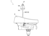
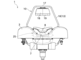
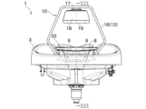
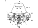
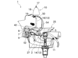
図3及び図4に示されているとおり、シャンプーボウル1は、施術の種類に応じて、スカルプマッサージ用装置10や頭浸浴装置25が取り付けられる。ここで、スカルプマッサージ用装置10及び頭浸浴装置25を図面に基づいて説明する。図5ないし10は、スカルプマッサージ用装置10の外観が示され、図11ないし15は、スカルプマッサージ用装置10がシャンプーボウル1に取り付けられた状態の外観が示されている。図16ないし25は、頭浸浴装置25の外観が示され、図26ないし31は、頭浸浴装置25がシャンプーボウル1に取り付けられた状態の外観及び断面が示されている。
As shown in Figures 3 and 4, the
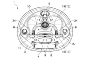
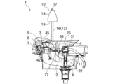
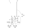
図5ないし10に示されているとおり、スカルプマッサージ用装置10は、シャワーヘッド5が接続される被接続部11と、この被接続部11に連結された流路部13と、この流路部13に連結された吐水部18と、流路部13に連結されてシャンプーボウル1に取り付けられる着脱部20とを有している。被接続部11は、上下に伸びた円筒状であって、上部に開口部12を有し、下部が流路部13に連結されている。開口部12は、シャワーヘッド5を固定するための着脱固定手段(図示省略)を有している。着脱固定手段は、例えば、紐やバンドでシャワーヘッド5を括り付けるもの、シャワーヘッド5を上から押さえ付ける錘としての頭浸浴装置25、開口部12とシャワーヘッド5とが螺合するネジ構造、機械的嵌合、開口部12をゴム製等とすることで開口部12とシャワーヘッド5との摩擦を生じさせるための素材の選択等である。
5 to 10, the
流路部13は、被接続部11の下部と連結された第一流路部14と、この第一流路部14の先端である第一先端部15に連結された第二流路部16とを有している。各流路部14,16は、内側が空洞であり、内側に流路が形成されている。第一流路部14は、被接続部11を中心として左右一対で構成されている。第一流路部14は、被接続部11から左右に向け伸びると共に前方に向けて湾曲又は屈曲し、第一先端部15が上方に向けられている。第一先端部15は、ヒンジ部23と軸支持部24とを有している。ヒンジ部23は、第二流路部16を回転させ、また、前後に移動させるものであり、このヒンジ部23を介して第二流路部16が連結されている。ヒンジ部23は、第二流路部16の可動域を限定するための規制部(図示省略)が形成されている。軸支持部24は、各第一先端部15の後部に形成された溝であり、頭浸浴装置25が取り付けられる際に用いられる(図31参照)。
The
第二流路部16は、左右の第一先端部15から上方に向けて伸びると共に側方に向けて湾曲又は屈曲し、先端である第二先端部17において連接されている。第二先端部17は、下部に吐水部18が連結されている。吐水部18の吐水口19は、シャンプーボウル1がある下方に向けられている。着脱部20は、シャンプーボウル1の底面2に当たる第一着脱部21と、シャンプーボウル1の排水口4に接続される第二着脱部22とを有している。第一着脱部21は、第一先端部15から下方に向けて突出し、ネジ構造等によって長さが調節される。第二着脱部22は、板状であって、被接続部11の直下において第一流路部14から下方に向けて突出している。第二着脱部22は、例えば、ゴム製、シリコン製等である。
The second
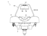
図11ないし15に示されているとおり、スカルプマッサージ用装置10は、シャンプーボウル1に取り付けられる。すなわち、スカルプマッサージ用装置10の第二着脱部22が、シャンプーボウル1の排水口4に挿入され、第二着脱部22の側面が排水口4の内面に当たることで、第二着脱部22が排水口4に嵌合する(図30及び31参照)。排水口4が円筒であるの対して、第二着脱部22は板状であるため、第二着脱部22と排水口4との間に隙間が生じる。したがって、湯水はこの隙間を通って排水口4から排水される。第一着脱部21は、シャンプーボウル1の底面2に当てられ、各流路部14,16を支持する。したがって、各流路部14,16は、各着脱部21,22によって三点で支持される。なお、使用時には、シャンプーボウル1のシャワーヘッド5が、被接続部11に接続される(図30参照)。
11 to 15, the
図15に示されているとおり、第二流路部16は、ヒンジ部23を介して、第一流路部14に対して角度が変化する。すなわち、第二流路部16は、後方に向けて傾斜する。ヒンジ部23は、規制部が形成されているため、可動域が限定され、所定の角度を超えて変化することが妨げられる。所定の角度は、第二流路部16の姿勢が垂直である場合をゼロ度としたとき、例えば、後方に向けて25ないし35度、好ましくは、30度程度であり、また、前方に向けて5ないし15度、好ましくは10度程度である。可動域が過度に大きい場合、スカルプマッサージ用装置10が、シャンプーボウル1に取り付けられる際、シャンプーボウル1の側面3等に接触して取付作業が妨げられる場合がある。
As shown in FIG. 15, the angle of the second
第二流路部16は、ヒンジ部23を介して前後方向に移動が可能である。すなわち、第二流路部16が回転する際の軸そのものの位置が変化する。
The second
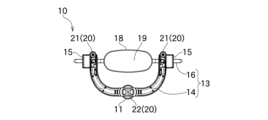
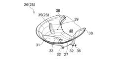
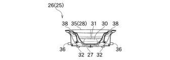
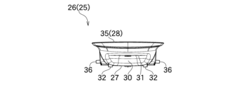
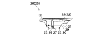
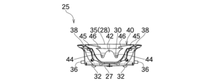
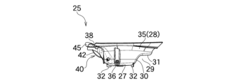
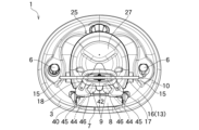
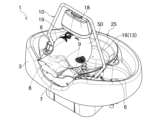
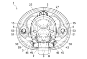
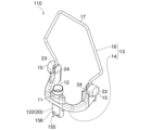
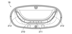
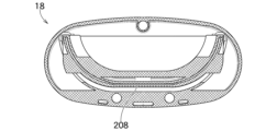
図16ないし25に示されているとおり、頭浸浴装置25は、例えば、洗面器等に近似し、僅かに漏斗状に窄まった桶状であり、桶本体部26と、首縁部としての整流部40とを有している。ここで、図16ないし20は、整流部40が桶本体部26に取り付けられる前の状態が示され、図21ないし25は、頭浸浴装置25として、整流部40が桶本体部26に取り付けられた状態が示されている。桶本体部26は、底部27と、この底部27の周縁に連接されると共に上方に向けて伸びた周側部28とを有している。底部27は段違いに形成され、周側部28の一部は、切り欠かれている。底部27が段違いに形成されたことで、底部27の奥側の外側に、窪み空間29が形成されている。すなわち、底部27の奥側には、上方に向けて伸びた底側部30が連接され、この底側部30の奥側には、段底部31が連接されている。底部27の下面には、自立するための複数の脚部32が形成されている。なお、脚部32の数、形状、長さ、位置等は任意である。底部27のほぼ中央には、排水孔33が形成されている。排水孔33には、栓34(図30参照)が着脱される。
As shown in Figures 16 to 25, the
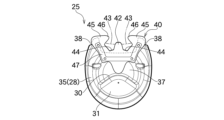
周側部28のうち、手前側であって、首載置具7と対峙する部位は、切り欠かれて首縁空隙48が形成されている。この首縁空隙48には、整流部40が着脱される。周側部28のうち、首縁空隙48以外の部位である外縁部35は、外面に軸突部36が形成されている。軸突部36は、左右一対で構成され、底側部30よりも手前側において、側方に向けて突出している。外縁部35の上縁であって、手前側である首縁空隙48の近傍には、左右一対の溝部38が形成されている。外縁部35のうち、首縁空隙48の近傍には、首縁空隙48の形状に沿って、複数の小孔39が形成されている。
The portion of the
整流部40は、例えば、ゴム製、シリコン製、ウレタン製等の薄板状であり、留め部材47によって桶本体部26の周側部28に留められ、首縁部を担う。留め部材47は、首縁空隙48に沿った形状であり、整流部40を、周側部28との間に挟んでネジ等を介して留める。整流部40は、周側部28に留められる周側本体部41と、この周側本体部41の上部に連接された対峙部42と、この対峙部42の左右両側が切り欠かれたことで形成された水流部43と、この水流部43の左右両側に形成された誘導部45とを有している。対峙部42は、周側本体部41の上端部の中央から上方に向けて突出している。対峙部42の左右両側が、周側本体部41に向けて下方に切り欠かれたことで、水流部43は、対峙部42よりも下方に形成されている。水流部43は、周側本体部41に向けて更に下方に切り欠かれたことで、被配置部44が形成されている。この被配置部44は、首載置具7の第二載置部9が配置される(図26参照)。誘導部45は、周側本体部41の上端部から上方に向けて伸びると共に、先端部である誘導先端部46が互いに近づく方向に張り出している。整流部40との関係において、溝部38の位置は、外縁部35の周方向に沿って、被配置部44(水流部43)及び誘導先端部46よりも外側に配置され、また、外縁部35から底部27に向けて水流部43よりも浅く切り欠かれている。
The
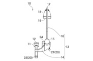
図26ないし31に示されているとおり、頭浸浴装置25は、スカルプマッサージ用装置10が取り付けられているシャンプーボウル1に取り付けられる。スカルプマッサージ用装置10の接続部11は、シャンプーボウル1のシャワーヘッド5が接続されており、頭浸浴装置25の段底部31が、シャワーヘッド5の上に載せられる。すなわち、頭浸浴装置25が、スカルプマッサージ用装置10の着脱固定手段を担う。なお、着脱固定手段は、紐やバンド等と併用することで実現してもよい。頭浸浴装置25の軸突部36は、スカルプマッサージ用装置10の軸支持部24に係止される。一方で、頭浸浴装置25の整流部40は、首載置具7の第二載置部9に取り付けられる。すなわち、整流部40の被配置部44に第二載置部9が嵌められ、被配置部44が閉塞すると共に、第二載置部9が水流部43に替わる。整流部40の対峙部42は、第二載置部9同士の間に嵌められる。誘導部45は、第二載置部9の外周に沿って嵌められる。整流部40は、首載置具7の第一載置部8と対峙する。頭浸浴装置25の底部27は、シャンプーボウル1の底面2よりも上方に配置され、底部27の排水孔33に栓34が取り付けられている。
26 to 31, the
以上のとおり、スカルプマッサージ用装置10及び頭浸浴装置25が構成されている。
The
次に、本実施形態の効果を、本実施形態の作用と共に説明する。図32ないし34は、本実施形態による施術の様子が示されている。 Next, the effects of this embodiment will be described along with the operation of this embodiment. Figures 32 to 34 show the treatment procedure according to this embodiment.
図32ないし34に示されているとおり、被施術者50が仰向けに横たわって頭部をシャンプーボウル1に置く。その際、被施術者50の首は、首載置具7の第一載置部8に載置される。更に、被施術者50のうなじ等が、第二載置部9に載置される。被施術者50の頭髪は、施術前にシャワーヘッド5からの湯水で濡らされる。頭髪が予め濡らされたことで、施術において湯水が頭髪で跳ね返ることが抑止される。仮に、頭髪が乾燥した状態で施術が行われると、スカルプマッサージ用装置10から放出された湯水は、頭髪に当たって跳ね返り、被施術者50の顔面や衣服に飛散する場合がある。
As shown in Figures 32 to 34, the person to be massaged 50 lies on his/her back and places his/her head in the
被施術者50の頭部がシャンプーボウル1に載置された状態で、スカルプマッサージ用装置10がシャンプーボウル1に取り付けられる。スカルプマッサージ用装置10の第二流路部16は、後方に倒された状態で取り付けられる。第二流路部16が後方に倒されたことで、吐水部18が被施術者50の顔面と対峙しない姿勢で、スカルプマッサージ用装置10がシャンプーボウル1に取り付けられる。仮に、第二流路部16が垂直の状態で、スカルプマッサージ用装置10がシャンプーボウル1に取り付けられると、他の施術の際に吐水部18に残っていた湯水が、被施術者50の顔面や衣服に掛る場合がある。
The
スカルプマッサージ用装置10の被接続部11に、シャワーヘッド5が接続される。着脱固定手段が、例えばバンド等であれば、シャワーヘッド5が被接続部11に括り付けられる。頭浸浴装置25は、後頭部の下方に配置され、スカルプマッサージ用装置10に取り付けられると共にシャワーヘッド5の上に載せられる。頭浸浴装置25がスカルプマッサージ用装置10に取り付けられることで、バンド等と併せた着脱固定手段が実現する。なお、頭浸浴装置25が、後頭部の下方に配置される際、被施術者50が長髪の場合、被施術者50の頭部が持ち上げられ、頭髪がすべて頭浸浴装置25の内側に収められる。
The
被施術者50の頭部が配置されたシャンプーボウル1に、スカルプマッサージ用装置10及び投信浴装置25が取り付けられた状態において、スカルプマッサージ用装置10の第二流路部16は、後方に倒されたままであるため、被施術者50の頭頂部側に配置され、頭皮や頭髪の生え際とは対峙していない。一方で、頭浸浴装置25の対峙部42は、被施術者50のうなじ等と対峙する。その際、対峙部42は、うなじ等と接触せず、うなじ等と対峙部42との間に、僅かな隙間が空く。なお、各載置部7,8に、首やうなじ等のどの部位が載置されるかは、被施術者50の体格によって僅かに異なる。
When the
シャンプーボウル1の止水栓6が操作され、湯水が供給されると、湯水は、シャワーヘッド5から放出される。シャワーヘッド5は、スカルプマッサージ用装置10の被接続部11に接続されているため、湯水は、被接続部11から、第一流路部14、第二流路部16を経て、吐水部18の吐水口19から放出される。放出された湯水は、被施術者50の頭部に当たらずに、頭浸浴装置25に溜まっていく。水位が頭浸浴装置25の底部27から徐々に上昇すると、後頭部が湯水に適度に浸り、水位が首載置具7の第二載置部9に至ると、湯水は、第二載置部9に沿って左右に迂回し(図33の水流51参照)、第二載置部9の左右から頭浸浴装置25の外側に溢れて流れる(図34の水流52参照)。その際、湯水は、対峙部42を超えて流れない。第二載置部9には、被施術者50のうなじ等が載置されているため、湯水は、第二載置部9に沿うと共にうなじ等を流れる。うなじ等は、静止した水面に浸かっているのではなく、流れ続ける湯水に晒されていることから、被施術者50は、うなじ等において不感を得ず、水流を感じてリラックスすることができる。
When the
湯水が流れる勢いによっては、湯水は、第二載置部9から誘導部45にも周り、誘導先端部46からうなじ等に向けて流れる(図33の水流53参照)。湯水が適切にうなじ等に向けられるため、被施術者50をリラックスさせることができる。
Depending on the force of the water flow, the water may flow from the
水位が第二載置部9に至ると、満水となるところ、この満水時において、被施術者50の後頭部が湯水に浸かっているため、被施術者50をリラックスさせることができる。また、頭部と共に頭髪が湯水に浸かることで、頭髪の汚れが落ちる。
When the water level reaches the
後頭部が湯水に適度に浸った後、または、湯水が第二載置部9の左右から頭浸浴装置25の外側に溢れて流れた後、第二流路部16の角度が調節され、吐水口19から放出された湯水が頭皮や頭髪の生え際に当たる位置に、第二流路部16が配置される。湯水は、頭皮や頭髪の生え際に当たり、頭髪を伝って頭頂部側に流れる(図34の水流54参照)。被施術者50は、後頭部が湯水に浸った後、または、うなじ等が湯水に晒された後に、頭皮や頭髪の生え際が、吐水口19からの湯水で適度に刺激されるため、うなじ等における流水を適切に感じることができる。仮に、吐水口19からの湯水が、頭皮や頭髪の生え際に当たりながら頭浸浴装置25に溜められると、うなじ等が湯水に晒される前に、頭皮や頭髪の生え際が刺激され、被施術者50は、うなじ等における感覚が薄れる場合がある。
After the back of the head is appropriately immersed in the hot water, or after the hot water overflows and flows out of the
施術の間、被施術者50は、上記のとおり、頭部が湯水に浸かり、うなじ等を湯水が流れることで、リラックスすることができ、一方で、施術者が他の業務を行っても、施術は継続されている。したがって、被施術者50にとって快適であると共に、施術者が他の業務を行っても差し支えが無い施術を行うことができる。なお、仮に、施術者が施術を行う場合であっても、スカルプマッサージ用装置10がシャワーの役割を担うため、施術者は、シャワーヘッド5を把持する必要が無く、両手で施術ができる。
During the treatment, as described above, the person being treated 50 can relax by having their head immersed in hot water and hot water running over their nape, etc., while the treatment continues even if the therapist performs other tasks. Therefore, the treatment is comfortable for the person being treated 50 and can be performed without interfering with the therapist performing other tasks. Even if the therapist is performing the treatment, the
また、シャンプーボウル1の底面2よりも高い位置に頭浸浴装置25の底部27が配置されるため(図34参照)、シャンプーボウル1に直接湯水を溜める場合と比較して、少量の湯水で足りる。
In addition, because the bottom 27 of the
本実施形態では、頭浸浴装置25における整流部40の被配置部44に、首載置具7の第二載置部9が嵌められる(図26参照)。すなわち、シャンプーボウル1に首載置具7が取り付けられていた場合であっても、第二載置部9が被配置部44に配置されることで、第二載置部9が整流部40と干渉しない。
In this embodiment, the second mounting
施術が終わると、止水栓6が操作され、湯水が止められる。第二流路部16が後方に倒され、被施術者50の頭部と対峙しない位置に配置される。したがって、流路部13に残留した湯水が吐水口19から滴っても、湯水が頭部に当たることは妨げられる。
When the treatment is finished, the
本実施形態では、頭浸浴装置25の底部27に排水孔33が形成され、栓34が取り付けられていることから(図30参照)、栓34を抜くことで、排水孔33から排水することができる。
In this embodiment, a
頭浸浴装置25が、スカルプマッサージ用装置10から取り外される。シャワーヘッド5が、スカルプマッサージ用装置10から取り外される。被施術者の濡れた頭髪は、タオル等の繊維製部材で水分が吸収される。
The
本実施形態では、頭浸浴装置25の整流部40が留め部材47を介して着脱される構造であるため(図16ないし25参照)、施術の種類や被施術者50の体格に応じて、様々な形状の整流部40を着脱することができる。また、整流部40は、ゴム製、シリコン製、ウレタン製等の薄板状であるため、容易に変形し、交換が容易である。
In this embodiment, the
本実施形態では、頭浸浴装置25における外縁部35の上縁であって、手前側である首縁空隙48の近傍には、左右一対の溝部38が形成されている(図22参照)。溝部38の位置は、外縁部35の周方向に沿って、被配置部44(水流部43)及び誘導先端部46よりも外側に配置され、また、溝部38は、外縁部35から底部27に向けて水流部43よりも浅く切り欠かれている。仮に、被施術者50の体格が大きく、頭浸浴装置25の対峙部42が被施術者50のうなじ等と接触した場合、第二載置部9がうなじ等で塞がれ、湯水がうなじ等を流れることが妨げられるところ、水流部43よりも浅い溝部38から湯水が流れることで、体格の大きな被施術者50のうなじ等に湯水を流すことができる。
In this embodiment, a pair of left and
なお、本発明の他の実施形態では、頭浸浴装置25は、被配置部44が形成されておらず、水流部43を有する(図21及び22参照)。この場合、水位が、頭浸浴装置25の底部27から徐々に上昇し、水流部43に至ると、対峙部42よりも低い水流部43から頭浸浴装置25の外側に溢れて流れる。その際、対峙部42が水流部43よりも高く形成されているため、湯水は、対峙部42を超えて流れない。水流部43は、被施術者のうなじ等と対面しているため、湯水は、被施術者のうなじ等を流れる。この場合、第二載置部9は、在っても無くてもよい。
In another embodiment of the present invention, the
次に、本実施形態で用いられるスカルプマッサージ用装置10の効果を説明する。
Next, we will explain the effects of the
スカルプマッサージ用装置10の第二流路部16は、第一流路部14の第一先端部15から上方に向けて伸びると共に側方に向けて湾曲又は屈曲している(図7参照)。この構成により、第二流路部16が、被施術者50の頭部と干渉することが無い。
The second
スカルプマッサージ用装置10の第一先端部15は、ヒンジ部23を有し、第二流路部16は、ヒンジ部23を介して、第一流路部14に対して角度が変化する(図15参照)。この構成により、吐水部18の位置が変化し、吐水口19から放出される湯水が頭皮に当たる位置を調節することができる。また、シャンプーボウル1への取付作業が容易となる。
The
また、ヒンジ部23は、第二流路部16の可動域を限定するための規制部が形成されている。この構成により、第二流路部16の可動域が限定され、所定の角度を超えて変化することが妨げられる。したがって、例えば、湯水が被施術者50の顔面にかかることが無い。
The
第二流路部16は、ヒンジ部23を介して前後方向に移動が可能である。したがって、被施術者50の生え際の位置に応じて、第二流路部16が適切に配置される。
The second
次に、スカルプマッサージ用装置10の変形例を図面に基づいて説明する。図35ないし37は、変形例に係るスカルプマッサージ用装置110が示されている。図35及び36は、スカルプマッサージ用装置110の外観が示され、図37は、スカルプマッサージ用装置110の第二着脱部122がシャンプーボウル1の排水口4に挿入された状態の断面が拡大されて示されている。なお、以下では、スカルプマッサージ用装置10と異なる構成が主に説明され、スカルプマッサージ用装置10と同じ構成は、同じ符号をもって説明が省略されている。
Next, modified examples of the
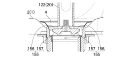
図35及び36に示されているとおり、スカルプマッサージ用装置110の第二着脱部122は、手前側面及び奥側面の下部から、手前側及び奥側に向って突出した一対のフランジ部155を有している。フランジ部155は、上方から視して、ほぼ半円形である。フランジ部155は、側方から視して、上面である平坦上面部156と、下面である傾斜下面部157とを有している。平坦上面部156は、平坦な半円板状であり、傾斜下面部157は、外側先端から第二着脱部122に向かうにしたがって徐々に下方に向けて傾斜している。
As shown in Figures 35 and 36, the second
図37に示されているとおり、第二着脱部122が、シャンプーボウル1の排水口4に挿入されると、フランジ部155は、排水口4の開口上端部よりも深い位置で、かつ、排水口4の内面と隙間を空けて配置される。排水口4から排水される湯水は、排水口4の中に取り付けられた網状の毛髪収集具(図示省略)を通過する。その際、湯水は、平坦上面部156から、傾斜下面部157を伝って排水口4の下方へ流れる。すなわち、流れた湯水は、ヘアキャッチャーに当たることで、被施術者50にとって不快な音を発する場合があるところ、湯水がフランジ部155を介して排水されることで、湯水の落下し始める位置が、シャンプーボウル1の底面2よりも低い傾斜下面部157の下端に下がるため、湯水の落下し始める位置から毛髪収集具に当たるまでの距離も短くなる。したがって、フランジ部155が無く底面2から湯水が落下し始める場合と比較して、消音効果が発揮され、被施術者50は、不快な音を感じることなく、リラックスすることができる。
As shown in FIG. 37, when the second
なお、本発明の他の実施形態では、頭浸浴装置のみがシャンプーボウルに取り付けられる。この場合、頭浸浴装置の脚部は、長く形成され、シャンプーボウルの底面において自立する。また、スカルプマッサージ用装置に替えて、台がシャンプーボウルに設置され、この台上に頭浸浴装置が載置される。スカルプマッサージ用装置が無くても、頭浸浴であれば、仮に、施術者が施術を行う場合であっても、施術者は、両手で施術ができるため、好適である。
他の実施形態では、脚部はフック状であり、シャンプーボウルの側面縁に引っ掛かる構造である。
他の実施形態では、脚部は、シャンプーボウルの排水口に嵌合する形状であり、例えば、スカルプマッサージ用装置の第二着脱部と同様の構成である。
他の実施形態は、脚部を有していない。
他の実施形態では、対峙部が、被施術者のうなじ等に僅かに接触する。
他の実施形態は、水流部を有していない。
他の実施形態では、整流部を有さず、整流部に相当する部位として、桶本体部に整流部と同等形状の首縁部が形成されている。
他の実施形態は、溝部を有していない。
他の実施形態では、栓が整流部と一体である。すなわち、整流部の下端部が排水孔まで伸び、当該下端部に栓が形成されている。
他の実施形態では、スカルプマッサージ用装置の第二流路部は、左右の片方のみである。
他の実施形態では、スカルプマッサージ用装置の第二着脱部の形状が、ほぼ円筒状であり、一部に、排水口との間に隙間を生じさせる切欠き、凹み、窪み、溝等が形成されている。当該隙間が、排水の流路となる。
他の実施形態では、湯水は、シャワーヘッドや他の給水器具等から頭浸浴装置に直接供給される。すなわち、湯水はスカルプマッサージ用装置を経ない。
他の実施形態では、首載置具が取り付けられておらず、首載置具に相当する部位として、シャンプーボウルにおける側面に、首載置具と同等形状の首載置部が形成されている。
In another embodiment of the present invention, only the head immersion device is attached to the shampoo bowl. In this case, the legs of the head immersion device are formed long and stand on the bottom surface of the shampoo bowl. Also, instead of the scalp massage device, a stand is installed on the shampoo bowl, and the head immersion device is placed on this stand. Even if there is no scalp massage device, if it is a head immersion, even if the therapist performs the treatment, the therapist can perform the treatment with both hands, so it is preferable.
In another embodiment, the legs are hook-shaped and are configured to hook onto the side edges of the shampoo bowl.
In another embodiment, the leg portion is shaped to fit over the drain of a shampoo bowl, for example in a similar configuration to the second removable portion of a scalp massaging device.
Other embodiments do not have legs.
In other embodiments, the facing portion slightly contacts the nape of the recipient's neck, etc.
Other embodiments do not have a water flow section.
In another embodiment, there is no straightening portion, and a neck edge portion having the same shape as the straightening portion is formed on the bucket main body as a portion equivalent to the straightening portion.
Other embodiments do not have grooves.
In another embodiment, the plug is integral with the flow straightener, i.e. the lower end of the flow straightener extends to the drain hole and the plug is formed at said lower end.
In another embodiment, the scalp massaging device has only one second flow passage portion, either on the left or right side.
In another embodiment, the shape of the second removable part of the scalp massage device is substantially cylindrical, and a notch, recess, depression, groove, or the like is formed in a part of the second removable part to create a gap between the drain outlet. The gap becomes a flow path for drainage.
In another embodiment, hot water is provided to the head soaking apparatus directly, such as from a shower head or other water supply, i.e., the hot water does not pass through the scalp massaging apparatus.
In another embodiment, the neck rest is not attached, and a neck rest part having the same shape as the neck rest is formed on the side of the shampoo bowl as a part corresponding to the neck rest.
次に、吐水部18を図面に基づいて説明する。図38ないし44は、吐水部18が示されている。図38ないし40は、吐水部18の外観が示され、図41ないし44は、吐水部18の断面が示されている。
Next, the
ここで、吐水部18は、スカルプマッサージ用装置10,110を構成する部材であり、スカルプマッサージ用装置10,110は、以下の構成である。
シャンプーボウル1に取り付けられてシャワーヘッド5が接続される被接続部11と、この被接続部11に連結されて上方に伸びた流路部13と、この流路部13の先端に連結された吐水部18とを有し、吐水部18の下面に形成された吐水口19は、被施術者50の額における頭髪の生え際に倣ってU字状であり、シャワーヘッド5からの湯水が流路部13を通って吐水部18に至り、吐水口19から放出される。
吐水口19から放出される湯水は、吐水口19から被施術者50の額に当たるまで、吐水口19のU字状に沿って途切れずに連続している。
吐水部18内の流路には、上下に連なった階層が形成されている。
階層同士の連絡路は、上層側と下層側とで互い違いにずれている。
Here, the
It has a connecting
The hot and cold water discharged from the
The flow path within the
The connecting passages between the levels are staggered on the upper and lower levels.
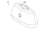
詳説すれば、図38ないし40に示されているとおり、吐水部18は、上方又は下方から視して楕円形又は長円形状の立体物であり、上部に流路接続部200を有し、下面部に吐水口19を有している。流路接続部200は、一対で構成され、流路部13の第二先端部17と連結される(図5参照)。吐水口19は、被施術者50の額における頭髪の生え際に倣ったU字状であり、側方に向ってU字の線状に連続している。なお、流路接続部は、単一であってもよい。また、吐水口は、複数の孔がU字状に並列したものであってもよい。
In more detail, as shown in Figures 38 to 40, the
図41に示されているとおり、吐水部18は、内部に流路を有し、流路には、上下に連なった三段の階層が形成されている。詳説すれば、流路は、吐水口19の内側から流路接続部200に接続された筒状の主流路部201と、この主流路部201の下端に連接されて左右に伸びたU字状の階層流路部202とで実現され、階層流路部202の下流側が吐水口19に通じている。階層流路部202は、内側に二つの区画片が形成されており、この第一区画片203及び第二区画片204によって上下三段の階層が形成されている。なお、階層の数は、二段でもよいし、四段以上であってもよい。区画片の数は、階層の数に応じて決定される。
As shown in FIG. 41, the
階層は、主流路部201に通じた上段層流路205と、この上段層流路205の下流側に通じた中段層流路206と、この中段層流路206の下流側に通じた下段層流路207と、この下段層流路207の下流側から吐水口19に通じた吐水口連絡路208と、上段層流路205と中段層流路206との間が第一区画片203によって区切られたことで形成された上中連絡路209と、中段層流路206と下段層流路207との間が第二区画片204によって区切られたことで形成された中下連絡路210とから構成されている。階層同士の各連絡路209,210は、上層側と下層側とで互い違いにずれている。すなわち、第一区画片203が後方(図41において右方)に向けて張り出して形成されたことで、上中連絡路209は、上段層流路205の後部及び中段層流路206の後部(図41において右寄り)に通じており、一方で、第二区画片204が前方(図41において左方)に向けて張り出して形成されたことで、中下連絡路210は、中段層流路206の前部及び下段層流路207の前部(図41において左寄り)に通じている。したがって、上中連絡路209と中下連絡路210とは、前後にずれて配置されている。流路は、階層流路部202内において前後に蛇行している。
The tiers are composed of an upper
階層同士の各連絡路209,210の前後幅は、下層にしたがって狭くなっている。詳説すれば、図42に示された上中連絡路209の前後幅よりも、図43に示された中下連絡路210の前後幅の方が狭く形成され、中下連絡路210の前後幅よりも、図44に示された吐水口連絡路208の前後幅及び図40に示された吐水口19の前後幅の方が狭く形成されている。図43に示されているとおり、中下連絡路210では、中央部位211の前後幅よりも、左右側方部位212の前後幅の方が、広く形成されている。
The front-to-rear width of each of the
以上のとおり、吐水部18が構成されている。次に、吐水部18の効果を、作用と共に説明する。
The
スカルプマッサージ用装置10,110に供給された湯水は、吐水部18において、主流路部201、階層流路部202を経て、吐水口19から放出される。階層流路部202では、湯水は、上段層流路205、上中連絡路209、中段層流路206、中下連絡路210、下段層流路207、吐水口連絡路208を蛇行し、吐水口19から、U字状で放出される。吐水口19から放出される湯水は、吐水口19から被施術者の額に当たるまで、吐水口19のU字状に沿って、水壁の如く途切れずに連続している。換言すれば、吐水口19のU字状に沿って途切れずに連続した湯水は、カーテン又はガラス面のようでもある。特に、中下連絡路210では、中央部位211の前後幅よりも、左右側方部位212の前後幅の方が、広く形成されているため、湯水の流量は、中央部位211よりも左右側方部位212の方が多くなり、途切れずに連続したU字状となる。
Hot water supplied to the
湯水は、被施術者50の頭皮や頭髪の生え際に当たり、頭髪を伝って頭頂部側に流れる(図34の水流54参照)。被施術者50は、頭皮や頭髪の生え際が、吐水口19からの湯水で適度に刺激され、リラックスすることができる。一方で、施術者が他の業務を行っても、施術は継続されている。したがって、被施術者50にとって快適であると共に、施術者が他の業務を行っても差し支えが無い施術を行うことができる。特に、湯水が、途切れずに連続したU字状であるため、被施術者50は、違和感を覚えることがない。なお、仮に、湯水が途切れたり、シャワーの如く複数の孔から個々に放出されたりした場合、被施術者50は、湯水が途切れて頭皮や頭髪の生え際に当たっていることが、感覚的にわかるため、違和感を覚え、雑念がリラクゼーションを妨げる場合がある。
The hot water hits the scalp and hairline of the person being treated 50 and flows down the hair toward the top of the head (see
以上、本発明の実施形態を詳述したが、本発明は上記実施形態に限定されるものではない。そして本発明は、特許請求の範囲に記載された事項を逸脱することがなければ、種々の設計変更を行うことが可能である。 Although the embodiment of the present invention has been described in detail above, the present invention is not limited to the above embodiment. Furthermore, various design modifications of the present invention are possible without departing from the scope of the claims.
1 シャンプーボウル
2 底面
3 側面
4 排水口
5 シャワーヘッド
6 止水栓
7 首載置具(首載置部)
8 第一載置部
9 第二載置部
10,110 スカルプマッサージ用装置
11 被接続部
12 開口部
13 流路部
14 第一流路部
15 第一先端部
16 第二流路部
17 第二先端部
18 吐水部
19 吐水口
20 着脱部
21 第一着脱部
22,122 第二着脱部
23 ヒンジ部
24 軸支持部
25 頭浸浴装置
26 桶本体部
27 底部
28 周側部
29 窪み空間
30 底側部
31 段底部
32 脚部
33 排水孔
34 栓
35 外縁部
36 軸突部
38 溝部
39 小孔
40 整流部(首縁部)
41 周側本体部
42 対峙部
43 水流部
44 被配置部
45 誘導部
46 誘導先端部
47 留め部材
48 首縁空隙
50 被施術者
52~54 水流
155 フランジ部
156 平坦上面部
157 傾斜下面部
200 流路接続部
201 主流路部
202 階層流路部
203 第一区画片
204 第二区画片
205 上段層流路
206 中段層流路
207 下段層流路
208 吐水口連絡路
209 上中連絡路
210 中下連絡路
211 中央部位
212 左右側方部位
1
Description of the Reference Signs 8: First mounting portion 9:
Description of the symbols 41: Circumferential main body portion 42: Opposing portion 43: Water flow portion 44: Placement portion 45: Guiding portion 46: Guiding tip portion 47: Fastening member 48: Neck edge gap 50: Person to be treated 52-54: Water flow 155: Flange portion 156: Flat upper surface portion 157: Sloped lower surface portion 200: Flow path connection portion 201: Main flow path portion 202: Layered flow path portion 203: First partition piece 204: Second partition piece 205: Upper layer flow path 206: Middle layer flow path 207: Lower layer flow path 208: Water outlet connection path 209: Upper-middle connection path 210: Middle-lower connection path 211: Central portion 212: Left and right side portions
Claims (6)
前記桶本体部に対して左右一対で構成されると共に、前記桶本体部の上方に向かう方向に向けて伸びた先の先端部で連接された内側が空洞の棒状部材と、
前記先端部の下部に連結された吐水部と、を有し、
前記棒状部材が、流路部となって湯水を前記先端部に送ると共に前記先端部から下方の前記吐水部に送り、
前記吐水部が、前記桶本体部の内側で前記被施術者の頭部に当てる湯水を、途切れずに連続したカーテン状として真下に放出し、
前記棒状部材が、後方に向けて倒れることで、湯水が頭部に当たる位置を調節することができる、
ことを特徴とする頭浸浴装置。 A bucket main body part attached to the inside of a shampoo bowl in which a person to be treated is to be treated;
A pair of hollow rod-shaped members are formed on the left and right sides of the tub main body, and are connected at their tips extending in an upward direction of the tub main body,
A water discharge portion connected to a lower portion of the tip portion,
The rod-shaped member serves as a flow path for sending hot and cold water to the tip portion and from the tip portion downward to the water discharge portion,
The water discharge unit discharges hot and cold water that hits the head of the person to be treated inside the tub main body directly below in the form of a continuous curtain,
The rod-shaped member can be tilted backward to adjust the position where the hot water hits the head.
A head immersion device characterized by the above.
ことを特徴とする請求項1に記載された頭浸浴装置。 An adjustment mechanism for adjusting the angle by rotating the rod-shaped member is provided.
2. A head immersion device according to claim 1.
ことを特徴とする請求項1に記載された頭浸浴装置。 The water outlet formed in the water outlet portion is linearly continuous toward the left and right,
2. A head immersion device according to claim 1.
ことを特徴とする請求項2に記載された頭浸浴装置。 The water outlet formed in the water outlet portion is linearly continuous toward the left and right,
3. A head immersion device according to claim 2.
ことを特徴とする請求項3又は請求項4に記載された頭浸浴装置。 The hair of the person to be treated is immersed in the tub main body.
5. A head immersion device according to claim 3 or 4.
ことを特徴とする請求項5に記載された頭浸浴装置。 The head of the patient is placed on the rod-shaped member in a fallen state.
6. A head immersion device according to claim 5.
Applications Claiming Priority (5)
| Application Number | Priority Date | Filing Date | Title |
|---|---|---|---|
| JP2021007970 | 2021-01-21 | ||
| JP2021007970 | 2021-01-21 | ||
| PCT/JP2022/001714 WO2022158472A1 (en) | 2021-01-21 | 2022-01-19 | Head immersion bath device and shampoo bowl |
| JP2022576707A JP7555616B2 (en) | 2021-01-21 | 2022-01-19 | Head soaking device and shampoo bowl |
| JP2024131951A JP2024149721A (en) | 2021-01-21 | 2024-08-08 | Head immersion bath device and head immersion method |
Related Parent Applications (1)
| Application Number | Title | Priority Date | Filing Date |
|---|---|---|---|
| JP2024131951A Division JP2024149721A (en) | 2021-01-21 | 2024-08-08 | Head immersion bath device and head immersion method |
Publications (2)
| Publication Number | Publication Date |
|---|---|
| JP2025094271A true JP2025094271A (en) | 2025-06-24 |
| JP7780227B2 JP7780227B2 (en) | 2025-12-04 |
Family
ID=82549417
Family Applications (3)
| Application Number | Title | Priority Date | Filing Date |
|---|---|---|---|
| JP2022576707A Active JP7555616B2 (en) | 2021-01-21 | 2022-01-19 | Head soaking device and shampoo bowl |
| JP2024131951A Pending JP2024149721A (en) | 2021-01-21 | 2024-08-08 | Head immersion bath device and head immersion method |
| JP2025057579A Active JP7780227B2 (en) | 2021-01-21 | 2025-03-31 | head immersion device |
Family Applications Before (2)
| Application Number | Title | Priority Date | Filing Date |
|---|---|---|---|
| JP2022576707A Active JP7555616B2 (en) | 2021-01-21 | 2022-01-19 | Head soaking device and shampoo bowl |
| JP2024131951A Pending JP2024149721A (en) | 2021-01-21 | 2024-08-08 | Head immersion bath device and head immersion method |
Country Status (5)
| Country | Link |
|---|---|
| EP (1) | EP4282300A4 (en) |
| JP (3) | JP7555616B2 (en) |
| KR (2) | KR102875848B1 (en) |
| CN (2) | CN121242344A (en) |
| WO (1) | WO2022158472A1 (en) |
Families Citing this family (1)
| Publication number | Priority date | Publication date | Assignee | Title |
|---|---|---|---|---|
| KR102822883B1 (en) * | 2023-01-26 | 2025-06-19 | 주식회사 에어라파 | Water circulation device for shampoo stand |
Citations (7)
| Publication number | Priority date | Publication date | Assignee | Title |
|---|---|---|---|---|
| JPS3613539Y1 (en) * | 1959-05-26 | 1961-05-26 | ||
| JPS4837097U (en) * | 1971-09-04 | 1973-05-04 | ||
| JPH03125857U (en) * | 1990-03-31 | 1991-12-19 | ||
| JP3080523U (en) * | 2001-03-22 | 2001-09-28 | 有限会社平野鉄工所 | Shower unit |
| JP2001292920A (en) * | 2000-04-12 | 2001-10-23 | Matsushita Electric Works Ltd | Shampooing/washing stand unit |
| JP2008253594A (en) * | 2007-04-06 | 2008-10-23 | Thales:Kk | Scalp washing device |
| JP2011212246A (en) * | 2010-03-31 | 2011-10-27 | Sanyo Electric Co Ltd | Automatic hair washing machine |
Family Cites Families (20)
| Publication number | Priority date | Publication date | Assignee | Title |
|---|---|---|---|---|
| US4651361A (en) * | 1985-10-07 | 1987-03-24 | Nolan William D | Portable combination hair shampoo basin and drying hood |
| US4901378A (en) * | 1989-01-19 | 1990-02-20 | Lealyce Reddell | Shampoo basin |
| JPH0617604U (en) * | 1992-08-19 | 1994-03-08 | 和泉電気株式会社 | Hair wash tank with drip prevention structure |
| WO1995004484A1 (en) * | 1993-08-11 | 1995-02-16 | Killey, Andrew, John | Hair washing support |
| JPH07289345A (en) * | 1994-04-27 | 1995-11-07 | N T M Watanabe:Kk | Shampoo bowl and supporting device thereof for barber and beauty parlor equipment |
| US5377365A (en) * | 1994-05-31 | 1995-01-03 | Hakim; Shaharazard H. | Neck support for beauty salon hair washing sinks |
| JP3100560B2 (en) * | 1997-04-30 | 2000-10-16 | 三洋電機株式会社 | Supports and automatic hair washer |
| JPH11164733A (en) * | 1997-12-03 | 1999-06-22 | Katsufumi Ito | Hair washing device |
| DE20319162U1 (en) * | 2003-12-11 | 2004-03-18 | Olymp Karl Herzog Gmbh & Co. | Edge locations is for edge section as neck support for washbasin user and comprises at least two locating segments which are deformable, being connectable with one another and relatively movable |
| JP4555633B2 (en) * | 2004-08-27 | 2010-10-06 | タカラベルモント株式会社 | Barber chair |
| JP3120306U (en) * | 2006-01-06 | 2006-03-30 | 友義 高 | Back support aid |
| KR100780046B1 (en) * | 2006-06-07 | 2007-11-29 | 송일호 | Medical hair dryer |
| CN201345965Y (en) * | 2008-12-26 | 2009-11-18 | 戴明家 | Portable hair washing device |
| DE102009046632A1 (en) * | 2009-11-11 | 2011-05-12 | Stefan Raab | showerhead |
| JP2011153522A (en) | 2011-05-20 | 2011-08-11 | Kobayashi Pharmaceutical Co Ltd | Chemical-solution feeding device |
| JP5807814B2 (en) * | 2013-03-06 | 2015-11-10 | タカラベルモント株式会社 | Head support device mounted on shampoo balls |
| JP3185374U (en) | 2013-05-29 | 2013-08-15 | 久忠 山内 | Shampoo bowl mounting pillow |
| JP6592318B2 (en) | 2015-09-29 | 2019-10-16 | 株式会社日本メディックス | Liquid massage device and supporting member thereof |
| JP2017077378A (en) * | 2015-10-21 | 2017-04-27 | タカラベルモント株式会社 | Shampoo bowl device and stream damming member |
| KR101982524B1 (en) * | 2017-08-24 | 2019-05-27 | (주)메드사피엔스 | Neck support for shampoo and shampoo apparatus for a hair salon |
-
2022
- 2022-01-19 CN CN202511678512.8A patent/CN121242344A/en active Pending
- 2022-01-19 KR KR1020237013162A patent/KR102875848B1/en active Active
- 2022-01-19 CN CN202280007065.1A patent/CN116437834B/en active Active
- 2022-01-19 JP JP2022576707A patent/JP7555616B2/en active Active
- 2022-01-19 EP EP22742594.9A patent/EP4282300A4/en active Pending
- 2022-01-19 WO PCT/JP2022/001714 patent/WO2022158472A1/en not_active Ceased
- 2022-01-19 KR KR1020257034975A patent/KR20250157458A/en active Pending
-
2024
- 2024-08-08 JP JP2024131951A patent/JP2024149721A/en active Pending
-
2025
- 2025-03-31 JP JP2025057579A patent/JP7780227B2/en active Active
Patent Citations (7)
| Publication number | Priority date | Publication date | Assignee | Title |
|---|---|---|---|---|
| JPS3613539Y1 (en) * | 1959-05-26 | 1961-05-26 | ||
| JPS4837097U (en) * | 1971-09-04 | 1973-05-04 | ||
| JPH03125857U (en) * | 1990-03-31 | 1991-12-19 | ||
| JP2001292920A (en) * | 2000-04-12 | 2001-10-23 | Matsushita Electric Works Ltd | Shampooing/washing stand unit |
| JP3080523U (en) * | 2001-03-22 | 2001-09-28 | 有限会社平野鉄工所 | Shower unit |
| JP2008253594A (en) * | 2007-04-06 | 2008-10-23 | Thales:Kk | Scalp washing device |
| JP2011212246A (en) * | 2010-03-31 | 2011-10-27 | Sanyo Electric Co Ltd | Automatic hair washing machine |
Also Published As
| Publication number | Publication date |
|---|---|
| CN116437834A (en) | 2023-07-14 |
| JP7780227B2 (en) | 2025-12-04 |
| WO2022158472A1 (en) | 2022-07-28 |
| JPWO2022158472A1 (en) | 2022-07-28 |
| CN121242344A (en) | 2026-01-02 |
| KR102875848B1 (en) | 2025-10-23 |
| KR20250157458A (en) | 2025-11-04 |
| EP4282300A1 (en) | 2023-11-29 |
| JP7555616B2 (en) | 2024-09-25 |
| CN116437834B (en) | 2025-12-05 |
| KR20230067682A (en) | 2023-05-16 |
| EP4282300A4 (en) | 2024-12-25 |
| JP2024149721A (en) | 2024-10-18 |
Similar Documents
| Publication | Publication Date | Title |
|---|---|---|
| JP7780227B2 (en) | head immersion device | |
| WO2005074856A1 (en) | Massage nozzle and massage device | |
| US8992450B1 (en) | Feminine hydro-therapeutic massage device | |
| KR101292178B1 (en) | Automatic bath machine | |
| AU2008201415B2 (en) | Scalp washing device | |
| WO2007114369A1 (en) | Shower bath system | |
| JP6997959B2 (en) | Bathtub | |
| WO2007116832A1 (en) | Shower bath system | |
| CA2590983C (en) | Feminine hydro-therapeutic massage device | |
| JP2024014322A (en) | Head bathing method | |
| JP2007222415A (en) | Bathtub apparatus provided with shampooing function | |
| JP3996681B2 (en) | Shower equipment | |
| JP2006006668A (en) | Bathtub | |
| US20040073996A1 (en) | Soft gel interior tub | |
| KR20240147884A (en) | bath apparatus for half the body using steam | |
| JP2001104191A (en) | Bathtub | |
| RU66952U1 (en) | BALNEOLOGICAL BATH "RELAX" | |
| KR200449701Y1 (en) | Whirlpool bathtub debris removal device | |
| JP2007252701A (en) | Bathtub apparatus | |
| JP2006055485A (en) | Shampoo basin | |
| JPH1118982A (en) | Shower equipment | |
| CA2307436A1 (en) | Bathtub design | |
| JP2001104037A (en) | Hair washing device | |
| JP2004160187A (en) | Massage nozzle and massage system | |
| JPH0852187A (en) | Special washing bath |
Legal Events
| Date | Code | Title | Description |
|---|---|---|---|
| A621 | Written request for application examination |
Free format text: JAPANESE INTERMEDIATE CODE: A621 Effective date: 20250331 |
|
| A871 | Explanation of circumstances concerning accelerated examination |
Free format text: JAPANESE INTERMEDIATE CODE: A871 Effective date: 20250331 |
|
| A131 | Notification of reasons for refusal |
Free format text: JAPANESE INTERMEDIATE CODE: A131 Effective date: 20250708 |
|
| A521 | Request for written amendment filed |
Free format text: JAPANESE INTERMEDIATE CODE: A523 Effective date: 20250829 |
|
| TRDD | Decision of grant or rejection written | ||
| A01 | Written decision to grant a patent or to grant a registration (utility model) |
Free format text: JAPANESE INTERMEDIATE CODE: A01 Effective date: 20251028 |
|
| A61 | First payment of annual fees (during grant procedure) |
Free format text: JAPANESE INTERMEDIATE CODE: A61 Effective date: 20251114 |
|
| R150 | Certificate of patent or registration of utility model |
Ref document number: 7780227 Country of ref document: JP Free format text: JAPANESE INTERMEDIATE CODE: R150 |