JP3107635U - Snow melting structure on roof and eaves - Google Patents
Snow melting structure on roof and eaves Download PDFInfo
- Publication number
- JP3107635U JP3107635U JP2004002791U JP2004002791U JP3107635U JP 3107635 U JP3107635 U JP 3107635U JP 2004002791 U JP2004002791 U JP 2004002791U JP 2004002791 U JP2004002791 U JP 2004002791U JP 3107635 U JP3107635 U JP 3107635U
- Authority
- JP
- Japan
- Prior art keywords
- roof
- snow
- eaves
- stop angle
- heater
- Prior art date
- Legal status (The legal status is an assumption and is not a legal conclusion. Google has not performed a legal analysis and makes no representation as to the accuracy of the status listed.)
- Expired - Fee Related
Links
Images

Landscapes
- Buildings Adapted To Withstand Abnormal External Influences (AREA)
Abstract
【課題】一般の家庭でも特別な工事も要せず、しかも雨樋や外壁の損傷もなく、氷魂や雪魂の落下による被害も防げる。
【解決手段】棒状ヒーターを屋根の雪止めアングルを利用して設置するものであって、ヒーターAを、雪止めアングル5より上部の屋根または軒先部分の屋根上にアングル金具5を利用して止め金具10によって固定されている。屋根工事も簡単で、電力の消費も少なく、経済的である。
【選択図】図2[PROBLEMS] No special construction is required even in ordinary households, and there is no damage to rain gutters and outer walls, and damage due to falling ice or snow souls can be prevented.
A bar heater is installed using a snow stop angle of a roof, and the heater A is stopped using an angle bracket 5 on the roof above the snow stop angle 5 or on the roof of the eaves portion. It is fixed by a metal fitting 10. The roof construction is simple, it consumes less power and is economical.
[Selection] Figure 2
Description
本考案は、屋根軒先の融雪を目的とするものであって、特に軒先に設置してある雪止めアングルより先の軒端部分の融雪構造に関する。 The present invention is intended to melt snow at the roof eaves, and particularly relates to a snow melting structure at the eaves end portion beyond the snow stop angle installed at the eaves.
雪国の生活では屋根上に積る雪の処理は大きな問題であり、種々の融雪・消雪装置が開発され、個々にはそれぞれ効果があって実用化されている。
屋根の融雪・消雪装置としては、屋根の棟上から温水を流すもの、屋根板下に発熱体を配置するもの、更には軒端に雪止め具を設けて雪塊の落下を防止するもの等様々の考案がある。 Snow melting / snow-removing devices for roofs, such as those that flow hot water from the top of the roof, those that place heating elements under the roof plate, and those that provide snow stoppers at the eaves edge to prevent snow blocks from falling There are various ideas.
しかし、これら公知の融雪・消雪装置は構造が複雑となるばかりか、モーターやポンプを使用するとか、屋根板を剥して改めて発熱体を敷設する等作業に手間がかかるばかりか、大掛りな工事となるため設備費も嵩むという欠点を有している。 However, these known snow-melting / snow-removing devices not only have a complicated structure, but also require a lot of work, such as using a motor or pump, stripping the roof plate, and laying a heating element again. Since it is a construction work, it has the disadvantage of increasing the equipment cost.
更には屋根上の積雪は徐々に軒端方向に移動して雪止めアングルがあるとしても、この部分で積雪があり、軒端で雪が巻き込む現象が生じて樋を破損することや、大きなツララとなって氷魂が落下して事故を起す原因となっている。 Furthermore, even if the snow on the roof gradually moves toward the edge of the eaves and there is a snow stop angle, there is snow on this part, causing the phenomenon of snow getting caught at the edge of the eaves, causing damage to the fence, and a large icicle The ice soul falls and causes an accident.
考案者は、この点に鑑み鋭意研究を重ねた結果本考案に到達したものであって、本考案は発熱体としてパイプ状体あるいは棒状体のヒーターを用い、このヒーターを屋根軒先の雪止めアングルより軒端部又は、雪止めアングルより上部屋根に配置することによって、軒先または屋根部分の雪を融かし、氷魂・雪塊の落下やスガモリを防止することができる。 The inventor has arrived at the present invention as a result of intensive research in view of this point. The present invention uses a pipe-shaped or rod-shaped heater as a heating element, and this heater is used as a snow guard angle at the roof eaves. By placing the eaves edge or the snow roof angle on the upper roof, it is possible to melt the snow at the eaves or the roof part and prevent the fall of ice souls / snow blocks and sugamori.
そして、このヒーターの取付けおよび管理はきわめて簡単容易であって、単に屋根上に配置し、雪止めアングルに支持させて電源に接続するのみで目的が達せられる。 The installation and management of the heater is very simple and easy, and can be achieved simply by placing it on the roof, supporting it on a snow stop angle and connecting it to a power source.
上述のように本考案の屋根軒先融雪構造は、ヒーターを線状あるいはパイプ状とし、雪止めアングルを利用して簡単に取付けられるため、一般の家庭でも特別な工事も要せず、しかも雨樋や外壁の損傷もなく、氷魂や雪塊の落下による被害も防げるという、従来からの屋根融雪装置に比較して顕著な作用効果を奏する。 As described above, the snow eaves structure of the roof eave according to the present invention has a heater or a linear shape and can be easily installed using a snow stop angle, so no special construction is required even in ordinary homes. There is no damage to the outer wall or the outer wall, and it can prevent damage caused by falling ice souls or snow blocks.
添付図面図1,図2を参照して、ヒーターは雪止め金具を利用して簡単に取付けられ、発熱体を外被の塩ビパイプに内接してあるため熱効率がよい。又、必要に応じて制御盤を設置し、温度センサー,降雪センサーを取り付けることができ、センサーにより自動運転も可能になるため実施化は容易である。 Referring to FIGS. 1 and 2, the heater is simply mounted using a snow stopper, and the heating element is inscribed in the outer PVC pipe so that the heat efficiency is good. In addition, if necessary, a control panel can be installed and a temperature sensor and a snowfall sensor can be attached, and automatic operation is possible with the sensor, so implementation is easy.
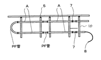
添付図面により本考案の実施例を説明すると、図1は屋根・軒先部の融雪ヒーターAの配設構造を示すものであって、図は屋根・軒先部分の略図であって、L金具は雪止めアングル(5)であり、雪国の屋根には通常設けられていて、積雪はこの雪止めアングル(5)によって、積雪の落下が止る構造となっている。 An embodiment of the present invention will be described with reference to the accompanying drawings. FIG. 1 shows an arrangement structure of a snow melting heater A at the roof and eaves, and the figure is a schematic view of the roof and eaves, and the L bracket is snow. A stop angle (5), which is normally provided on the roof in a snowy country, has a structure in which the snowfall is stopped by the snow stop angle (5).
しかし、この雪止めアングル(5)より上部は雪止めアングルで止まった雪が積雪化、又は雪塊化し融けにくい。また、軒端側に積った雪は雪塊となって落下するおそれがあり、またツララが大きくなって雨樋を破壊する原因ともなる。このため本考案は、この雪止めアングル(5)より上部、または雪止めアングル以下の軒先部分の融雪構造であって、
図示するようにパイプ状の融雪ヒーターAを必要本数だけ設けるものである。
However, in the upper part of the snow stop angle (5), the snow stopped at the snow stop angle is accumulated in snow or snow mass and is not easily melted. Moreover, the snow piled up on the eaves end side may fall as a snow lump, and the icicles may become large and destroy the gutter. For this reason, this invention is the snow melting structure of the eaves part above this snow stop angle (5) or below the snow stop angle,
As shown in the figure, a necessary number of pipe-shaped snow melting heaters A are provided.
図2は屋根上のヒーターAの配置図であって、雪止めアングル(5)より上部の屋根または軒先部分の屋根上にアングル金具(5)を利用して止め金具(10)によって固定されている。図中の(7)は継ぎ手を示している。 FIG. 2 is a layout diagram of the heater A on the roof, which is fixed by the fastener (10) using the angle bracket (5) on the roof above the snow stop angle (5) or the roof of the eaves portion. Yes. (7) in the figure indicates a joint.
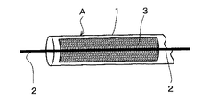
図3はパイプ状の融雪ヒーターAの断面図であって、図により説明すると、(1)は筒状の塩ビ製パイプで、この中に蓄熱用砂(3)を詰め、この芯に発熱用の伝熱線(2)を挿通して構成されているため熱効率がよく、融雪パイプとして図1,図2のように使用する。 FIG. 3 is a cross-sectional view of the pipe-shaped snow melting heater A, which will be explained with reference to the figure. (1) is a cylindrical PVC pipe, which is filled with heat storage sand (3), and this core is used for heat generation. Since the heat transfer wire (2) is inserted, the heat efficiency is good and the snow melting pipe is used as shown in FIGS.
本考案の屋根軒先融雪構造によるときは、屋根上の雪止めアングルより下の雪を融かし、危険な雪のせり出しや、雪崩を防ぎ、ツララを無くすことができる。 When the snow eaves structure of the roof eaves of the present invention is used, the snow below the snow stop angle on the roof can be melted to prevent dangerous snow from sticking out and avalanches, and to eliminate icicles.
しかも、屋根内部に設置するものでなく、屋根上に直接取付けるパイプ構造のため、既存の屋根に簡単に取付ができるため工事費も安く、工期も短くなるため広くの実施化が可能となる。 In addition, since the pipe structure is not directly installed on the roof but directly on the roof, it can be easily attached to the existing roof, so the construction cost is low and the construction period is shortened.
1 塩ビパイプ
2 発熱体
3 蓄熱体
5 雪止めアングル
6 雨樋
7 継ぎ手
8 電源
9 立桶
10 止め金具
A 軒先融雪ヒーター
1 PVC pipe
2 Heating element
3 thermal storage
5 Snow stop angle
6 Gutter
7 Fitting
8 Power supply
9 Vertical
10 Fastener
A eaves snowmelt heater
Claims (1)
A heating element (2) is provided in the PVC pipe (1) to form a pipe-shaped heater A, and the bar-shaped heater A is provided on the roof edge side and / or on the roof side from the roof snow stop angle (5). Features a snow melting structure on the roof and eaves.
Priority Applications (1)
| Application Number | Priority Date | Filing Date | Title |
|---|---|---|---|
| JP2004002791U JP3107635U (en) | 2004-05-19 | 2004-05-19 | Snow melting structure on roof and eaves |
Applications Claiming Priority (1)
| Application Number | Priority Date | Filing Date | Title |
|---|---|---|---|
| JP2004002791U JP3107635U (en) | 2004-05-19 | 2004-05-19 | Snow melting structure on roof and eaves |
Publications (1)
| Publication Number | Publication Date |
|---|---|
| JP3107635U true JP3107635U (en) | 2005-02-03 |
Family
ID=43270335
Family Applications (1)
| Application Number | Title | Priority Date | Filing Date |
|---|---|---|---|
| JP2004002791U Expired - Fee Related JP3107635U (en) | 2004-05-19 | 2004-05-19 | Snow melting structure on roof and eaves |
Country Status (1)
| Country | Link |
|---|---|
| JP (1) | JP3107635U (en) |
Cited By (1)
| Publication number | Priority date | Publication date | Assignee | Title |
|---|---|---|---|---|
| JP3108050B2 (en) | 1997-12-05 | 2000-11-13 | 株式会社スイデン | Cool storage cooler |
-
2004
- 2004-05-19 JP JP2004002791U patent/JP3107635U/en not_active Expired - Fee Related
Cited By (1)
| Publication number | Priority date | Publication date | Assignee | Title |
|---|---|---|---|---|
| JP3108050B2 (en) | 1997-12-05 | 2000-11-13 | 株式会社スイデン | Cool storage cooler |
Similar Documents
| Publication | Publication Date | Title |
|---|---|---|
| US5391858A (en) | Ice dam melting system | |
| RU2158809C1 (en) | Rain-water goods with electric heating | |
| US20060096968A1 (en) | Roof Deicing Apparatus | |
| JP3524891B2 (en) | Snow melting structure of eaves gutter | |
| CN213234045U (en) | Energy-saving snow melting device | |
| JP6106302B1 (en) | Roof snow melting equipment | |
| CN223853720U (en) | An automatic snow melting heating device for the eaves of a steel-structured color steel house. | |
| JP5006574B2 (en) | Snow plow removal device | |
| CN203049945U (en) | Roof | |
| JP4052630B2 (en) | Snow melting roof structure | |
| JP7698357B1 (en) | Geothermal snow melting system | |
| JP3093672U (en) | Freezing-mitigation eaves snow removal equipment | |
| CN215631131U (en) | Roof ice and snow melting device | |
| RU2305734C1 (en) | Heated rainwater gutter head | |
| JPH0921215A (en) | Roof snow removal equipment | |
| JP3162852U (en) | Roof snowfall system with self-temperature controlled heater wire | |
| CN202810019U (en) | Eaves gutter with function of automatic snow removal | |
| JP2541709Y2 (en) | Roof snow melting eaves | |
| JPH0642122A (en) | Roof snow melting equipment | |
| JP2010007272A (en) | Snow-melting roof | |
| RU68553U1 (en) | DEVICE FOR PROTECTING A DRAINAGE PIPE FROM FREEZING WATER IN IT | |
| JP4092390B2 (en) | Ice pillar prevention device | |
| JP2010281052A (en) | Reticulated material mixed with infrared ray generating material | |
| US20170051509A1 (en) | Ice Concentration Prevention Mechanism | |
| JPH0354270Y2 (en) |
Legal Events
| Date | Code | Title | Description |
|---|---|---|---|
| R150 | Certificate of patent or registration of utility model |
Free format text: JAPANESE INTERMEDIATE CODE: R150 |
|
| LAPS | Cancellation because of no payment of annual fees |