JP3114709U - Cylinder device - Google Patents
Cylinder device Download PDFInfo
- Publication number
- JP3114709U JP3114709U JP2005005558U JP2005005558U JP3114709U JP 3114709 U JP3114709 U JP 3114709U JP 2005005558 U JP2005005558 U JP 2005005558U JP 2005005558 U JP2005005558 U JP 2005005558U JP 3114709 U JP3114709 U JP 3114709U
- Authority
- JP
- Japan
- Prior art keywords
- cylinder
- piston
- tube
- cylinder unit
- piston rod
- Prior art date
- Legal status (The legal status is an assumption and is not a legal conclusion. Google has not performed a legal analysis and makes no representation as to the accuracy of the status listed.)
- Expired - Fee Related
Links
Images




Landscapes
- Actuator (AREA)
Abstract
【課題】2個のシリンダユニットを使用した簡素化された構成で、伸張速度の高速化と伸張動作の安定化とが可能なシリンダ装置を提供する。
【解決手段】第1及び第2シリンダユニット10,20のチューブ11,21を、軸心を一致させた状態で、後端部を結合する。また、第1シリンダユニット10のピストンロッド13の先端を、固定台30の縦壁30aに連結する。そして、前記チューブ11,21を軸心方向に移動自在に支持するガイドレール32とスライダ33,33とを備える。
【選択図】図1Provided is a cylinder device capable of increasing an extension speed and stabilizing an extension operation with a simplified configuration using two cylinder units.
The rear ends of the tubes 11 and 21 of the first and second cylinder units 10 and 20 are joined in a state where the axes are aligned. Further, the tip of the piston rod 13 of the first cylinder unit 10 is connected to the vertical wall 30 a of the fixed base 30. And the guide rail 32 and the sliders 33 and 33 which support the said tubes 11 and 21 movably to an axial center direction are provided.
[Selection] Figure 1
Description
本考案は、空気圧や油圧等の流体圧を利用したシリンダユニットを2個連結したシリンダ装置に関し、流体圧シリンダ装置の技術分野に属する。 The present invention relates to a cylinder device in which two cylinder units using fluid pressure such as air pressure and hydraulic pressure are connected, and belongs to the technical field of fluid pressure cylinder devices.
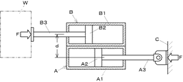
従来より、被加工物や治工具等を移動推進させる流体圧を利用したシリンダが多方面で実用されており、その中に、ピストンストロークの拡大を図るものがある。例えば特許文献1には、図11に示すようなシリンダ装置が示唆されている。すなわち、このシリンダ装置は、一対の単段シリンダユニットA,Bを有し、各シリンダユニットA,BのチューブA1,B1に摺動自在に収納されたピストンA2,B2から延びるピストンロッドA3,B3が、互いに逆方向に進退するように束ねられた構成のものである。そして、一方のシリンダユニットAのピストンロッドA3は固定部材Cに、他方のシリンダユニットBのピストンロッドB3は移動対象物Wに、それぞれ連結されている。 2. Description of the Related Art Conventionally, cylinders using fluid pressure for moving and propelling workpieces and jigs and tools have been put to practical use in various fields, and among them, piston strokes can be expanded. For example, Patent Document 1 suggests a cylinder device as shown in FIG. That is, this cylinder apparatus has a pair of single-stage cylinder units A and B, and piston rods A3 and B3 extending from pistons A2 and B2 slidably accommodated in tubes A1 and B1 of the cylinder units A and B, respectively. However, it is the thing of the structure bundled so that it might advance / retreat to the opposite direction mutually. The piston rod A3 of one cylinder unit A is connected to the fixed member C, and the piston rod B3 of the other cylinder unit B is connected to the moving object W.
これにより、ピストンロッドA3,B3が後退したときの長さ寸法を小型化した上で、同じ長さ寸法の1個のシリンダユニットの場合に比較してピストンストロークは確実に拡大される。さらに、各シリンダユニットA,Bに所定流量の圧力流体が一斉に供給されると、同じ流量の圧力流体が供給された同じ長さ寸法の1個のシリンダユニットの場合に比較して、伸張速度を2倍に増加させることができるようになる。 As a result, the length of the piston rods A3 and B3 when retracted is reduced, and the piston stroke is reliably expanded as compared with the case of one cylinder unit having the same length. Further, when the pressure fluid of a predetermined flow rate is supplied to each cylinder unit A, B at the same time, the expansion speed is higher than that in the case of one cylinder unit of the same length dimension supplied with the pressure fluid of the same flow rate. Can be increased by a factor of two.
ところで、前記シリンダ装置では、一対のピストンロッドA3,B3の軸心が距離dだけオフセットされていることから、固定部材C側における反力Fと移動対象物W側における反力Fとにより偶力M=d×Fが発生し、その結果、対象物Wを真直ぐに移動させることができず、また、推力が損なわれて、安定した伸張動作を図ることができないという問題が生じることがある。 By the way, in the cylinder device, since the shaft centers of the pair of piston rods A3 and B3 are offset by a distance d, a couple of forces is generated by the reaction force F on the fixed member C side and the reaction force F on the moving object W side. M = d × F occurs, and as a result, there is a problem that the object W cannot be moved straight, the thrust is impaired, and a stable extension operation cannot be achieved.
前記問題を解消するには、例えば前記特許文献1の図3に記載のように、発生する偶力を互いに打ち消し合うように前記シリンダ装置を2組対照的に結合することが考えられるが、その場合には、シリンダユニットの数が2倍になって装置が大型化すると共に、圧力流体の供給先であるチューブ内の伸張室や伸縮室の数も2倍になって圧力流体の給排制御が複雑化するという問題が生じることになる。 In order to solve the problem, for example, as shown in FIG. 3 of the Patent Document 1, it is conceivable to couple the cylinder devices in a contrasting manner so that the generated couples cancel each other. In this case, the number of cylinder units is doubled to increase the size of the device, and the number of expansion chambers and expansion chambers in the tube to which the pressure fluid is supplied is doubled to control the supply and discharge of pressure fluid. This leads to the problem of increasing complexity.
そこで、本考案は、2個のシリンダユニットを使用した簡素化された構成で、伸張速度の高速化と伸張動作の安定化とが可能なシリンダ装置の提供を課題とする。 Therefore, an object of the present invention is to provide a cylinder device that can increase the extension speed and stabilize the extension operation with a simplified configuration using two cylinder units.
前記課題を解決するため、本考案は次のように構成したことを特徴とする。 In order to solve the above problems, the present invention is configured as follows.
まず、請求項1に記載の考案は、シリンダチューブと、該チューブに摺動自在に収納され、チューブ内を伸張室と収縮室とに画成するピストンと、該ピストンに連結され、チューブの前端側から外部に突出するピストンロッドとを有するシリンダユニットを2個備えたシリンダ装置であって、前記両シリンダユニットのチューブが、軸心を一致させた状態で、後端部を結合することにより一体化されていると共に、この一体化チューブを軸心方向に移動自在に支持するガイド機構と、一方のユニットのピストンロッドの先端が連結された固定部材とを有することを特徴とする。 First, the device according to claim 1 is a cylinder tube, a piston slidably accommodated in the tube, and a piston defining an extension chamber and a contraction chamber in the tube, and a piston connected to the piston. A cylinder device having two cylinder units each having a piston rod projecting outward from the side, wherein the tubes of both cylinder units are integrated by joining the rear end portions with their axes aligned. And a guide mechanism that supports the integrated tube so as to be movable in the axial direction, and a fixing member to which the tip of the piston rod of one unit is connected.
また、請求項2に記載の考案は、前記請求項1に記載のシリンダ装置において、前記各シリンダユニットは、ピストンストロークが互いに異なっていることを特徴とする。
The invention described in
そして、請求項3に記載の考案は、前記請求項1または請求項2に記載のシリンダ装置において、前記各シリンダユニットは、ピストンの受圧面積が互いに異なっていることを特徴とする。
The invention described in
まず、請求項1に記載の考案によれば、2個のシリンダユニットの伸張室に一斉に所定流量の圧力流体を供給することにより、各ピストンロッドは一斉に互いに逆方向へ前進しようとする。すなわち、固定部材側のピストンロッドが前進しようとすると、該ピストンロッドの先端が固定部材に連結されていることから、該ピストンロッド側のチューブが前記固定部材から遠ざかるように移動すると共に、他方のシリンダユニットのピストンロッドが前進することになる。その結果、例えば、同じピストンストロークの2個のシリンダユニットを使用した本考案のシリンダ装置と前記ピストンストロークと同じピストンストロークの1個のシリンダユニットとを比較すると、前記所定流量と同じ流量の圧力流体がそれぞれ供給された場合、前者の伸張速度は後者の伸張速度の2倍となり、伸張速度の高速化が可能となる。 First, according to the first aspect of the present invention, by supplying a predetermined flow rate of pressure fluid all at once to the extension chambers of the two cylinder units, the piston rods try to advance simultaneously in the opposite directions. That is, when the piston rod on the fixed member side tries to move forward, the tip of the piston rod is connected to the fixed member, so that the tube on the piston rod side moves away from the fixed member, and the other The piston rod of the cylinder unit moves forward. As a result, for example, when comparing the cylinder device of the present invention using two cylinder units having the same piston stroke with one cylinder unit having the same piston stroke as the piston stroke, the pressure fluid having the same flow rate as the predetermined flow rate is compared. Are respectively supplied, the former stretching speed is twice that of the latter, and the stretching speed can be increased.
その上で、2個のシリンダユニットを使用する構成であるので、装置の大型化や圧力流体の給排制御の複雑化を招くことはなく、しかも、連結された2個のシリンダユニットのピストンロッドの軸心が一致するので、偶力は発生しない。したがって、簡素化された構成で伸張動作の安定化が可能となる。 In addition, since it is configured to use two cylinder units, there is no increase in the size of the device or complicated supply / discharge control of pressure fluid, and the piston rods of the two connected cylinder units Since the axes of the two coincide, no couple is generated. Therefore, the extension operation can be stabilized with a simplified configuration.
さらに、シリンダ装置の作動に応じてチューブが移動する際には、該チューブはガイド機構により安定して支持されるので、伸張動作の安定化が一層助勢される。 Further, when the tube moves in accordance with the operation of the cylinder device, the tube is stably supported by the guide mechanism, so that stabilization of the extension operation is further assisted.
次に、請求項2に記載の考案によれば、各シリンダユニットのピストンストロークが互いに異なっているので、シリンダ装置の目的に応じて多様な伸張パターンを選択することができる。例えば、ピストンストロークの長いシリンダユニットのみを作動させる場合と、ピストンストロークの短いシリンダユニットのみを作動させる場合と、両シリンダユニットを作動させる場合とで、都合3通りのピストンストロークが実現される。 According to the second aspect of the present invention, since the piston strokes of the cylinder units are different from each other, various extension patterns can be selected according to the purpose of the cylinder device. For example, three types of piston strokes are realized by operating only a cylinder unit having a long piston stroke, operating only a cylinder unit having a short piston stroke, and operating both cylinder units.
そして、請求項3に記載の考案によれば、各シリンダユニットのピストンの受圧面積が互いに異なっているので、シリンダ装置の目的に応じて適切な推力を選択することができる。一例として、シリンダ装置の起動時には一般に大きな推力が必要とされることから、その場合には、まず大きな推力を得るべく受圧面積の大きいピストンを有するシリンダユニットを作動させ、次いで受圧面積の小さいピストンを有するシリンダユニットを作動させることにより、対象物の速やかな移動が可能となる。 According to the third aspect of the present invention, since the pressure receiving areas of the pistons of the cylinder units are different from each other, an appropriate thrust can be selected according to the purpose of the cylinder device. As an example, since a large thrust is generally required when starting the cylinder device, in this case, first, a cylinder unit having a piston with a large pressure receiving area is operated to obtain a large thrust, and then a piston with a small pressure receiving area is operated. By actuating the cylinder unit, the object can be quickly moved.
以下、本考案の実施の形態に係るシリンダ装置について説明する。 Hereinafter, a cylinder device according to an embodiment of the present invention will be described.
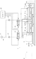
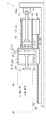
図1に示す第1の実施の形態に係るシリンダ装置1は、移動対象物Wを所定方向a,bに最長で距離Lだけ移動させるためのもので、2個のシリンダユニット10,20が後端部を介して連結されると共に固定台30に支持される構成とされている。
A cylinder device 1 according to the first embodiment shown in FIG. 1 is for moving a moving object W in a predetermined direction a, b by a distance L at the longest. It is configured to be connected via the end and supported by the
移動対象物Wとは反対側つまり固定台30の縦壁30a側の第1シリンダユニット10は、中空のチューブ11と、該チューブ11に摺動自在に収納され、チューブ11内を伸張室11aと収縮室11bとに画成するピストン12と、該ピストン12に一方の端部が連結され、チューブ11の前端側(図例では右側)から他方の端部が外部に突出するピストンロッド13とを有している。また、前記チューブ11の両端部に、前記伸張室11aに開口する第1ポート11cと前記収縮室11bに開口する第2ポート11dとがそれぞれ設けられており、両ポート11c,11dを介した圧力流体の給排が可能とされている。そして、前記ピストンロッド13の他方の端部は、連結部材14を介して固定台30の縦壁30aに固設された取付部材31に連結されている。
The
移動対象物W側の第2シリンダユニット20は、前記第1シリンダユニット10と同様の構成とされており、中空のチューブ21と、該チューブ21に摺動自在に収納され、チューブ21内を伸張室21aと収縮室21bとに画成するピストン22と、該ピストン22に一方の端部が連結され、チューブ21の前端側(図例では左側)から他方の端部が外部に突出するピストンロッド23とを有している。また、前記チューブ21の両端部に、前記伸張室21aに開口する第1ポート21cと前記収縮室21bに開口する第2ポート21dとがそれぞれ設けられており、両ポート21c,21dを介した圧力流体の給排が可能とされている。そして、前記ピストンロッド23の他方の端部は、作用部材24を介して移動対象物Wに連結されている。
The
その場合、前記両シリンダユニット10,20のチューブ11,21は、後端部が結合されて一体化されている。また、前記両シリンダユニット10,20のピストンロッド13,23は、軸心が一致している。さらに、両シリンダユニット10,20のピストンストロークは、それぞれ前記距離Lの1/2とされている。
In that case, the rear ends of the
また、固定台30に、このシリンダ装置1の伸縮方向つまり矢印a,b方向に沿って延びるガイドレール32が固設されており、このガイドレール32に、2個のスライダ33,33が移動自在に支持されている。そして、これらのスライダ33,33は、それぞれ前記チューブ11,21に結合されている。
Further, a
次に、このシリンダ装置1における圧力流体の給排システムについて説明する。 Next, a pressure fluid supply / discharge system in the cylinder device 1 will be described.
図1に示すように、コンプレッサ等の圧力流体源41から各シリンダユニット10,20の第1及び第2ポート11c,11d,21c,21dに接続する配管42が設けられている。各シリンダユニット10,20への配管42には流量調整弁43と電磁切換弁44とが介設されている。流量調整弁43は、絞り弁と逆止弁とで構成されている。電磁切換弁44は、図例の3位置で各シリンダユニット10,20に対する圧縮空気の給排を切り換えるもので、コントローラ45により位置つまり連通状態の切り換えが制御される。
As shown in FIG. 1, a
ここで、このシリンダ装置1の作用について説明する。 Here, the operation of the cylinder device 1 will be described.
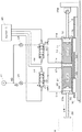
まず、図2に示すように、圧力流体源41からの圧縮空気が、流量調整弁43,43により所定流量とされて両シリンダユニット10,20の第1ポート11c,21cを介して伸張室11a,21aに供給されると共に、収縮室11b,21bが第2ポート11d,21dを介して大気に連通するように、コントローラ45は電磁切換弁44,44の作動を制御する。
First, as shown in FIG. 2, the compressed air from the
すなわち、第1シリンダユニット10側では、第1ポート11cを介して伸張室11aに供給された圧縮空気によりピストン12つまりピストンロッド13が前進しようとする。その場合、該ピストンロッド13の先端は固定台30の縦壁30aに連結されているので、第1シリンダユニット10のチューブ11と第2シリンダユニット20のチューブ21とが、スライダ33,33を介してガイドレール32に支持されつつ縦壁30aとは反対方向つまり矢印a方向に移動することになる。
That is, on the
一方、第2シリンダユニット20側では、第1ポート21cを介して伸張室21aに供給された圧縮空気によりピストン22つまりピストンロッド23が前進するので、該ピストンロッド23の先端に連結された移動対象物Wは、両シリンダユニット10,20のピストンストロークの総和だけ、つまり前記距離Lだけ矢印a方向に移動することになり、もってこのシリンダ装置1は伸張状態となる。
On the other hand, on the
次いで、図3に示すように、コントローラ45により電磁切換弁44,44が3位置のうちの中央位置となるように作動すると、圧力流体源41と両シリンダユニット10,20との間が遮断されると共に、両シリンダユニット10,20の各伸張室11a,21a及び各収縮室11b,21bは閉鎖される。すなわち、各伸張室11a,21aに圧縮空気が封じ込められて、このシリンダ装置1は伸張状態に保持されることになる。
Next, as shown in FIG. 3, when the
そして、図4に示すように、圧力流体源41からの圧縮空気が両シリンダユニット10,20の第2ポート11d,21dを介して収縮室11b,21bに供給されると共に、伸張室11a,21aが第1ポート11c,21cを介して大気に連通するように、コントローラ45が電磁切換弁44,44の作動を制御すると、供給された圧縮空気により両シリンダユニット10,20のピストン12,22つまりピストンロッド13,23が後退しようとする。
Then, as shown in FIG. 4, compressed air from the
すなわち、後退しようとする第1シリンダユニット10のピストンロッド13の先端は固定台30の縦壁30aに連結されているので、第1シリンダユニット10のチューブ11ひいては第2シリンダユニット20のチューブ21は、前記縦壁30a方向つまり矢印b方向に引き寄せられ、かつ、後退しようとする第2シリンダユニット20のピストンロッド23を介して移動対象物Wも前記矢印b方向に移動して、元の位置に戻ることになる。なお、その際、チューブ11,21は、スライダ33,33を介してガイドレール32に支持されつつ移動する。
That is, since the tip of the
その場合、まず、2個のシリンダユニット10,20の伸張室11a,21aに一斉に所定流量の圧縮空気を供給することにより、各ピストンロッド13,23は一斉に互いに逆方向へ前進しようとする。すなわち、固定台30の縦壁30a側のピストンロッド13が前進しようとすると、該ピストンロッド13の先端が前記縦壁30aに連結されていることから、該ピストンロッド13側のチューブ11が前記縦壁30aから遠ざかるように移動すると共に、移動対象物W側のピストンロッド23が前進することになる。その結果、例えば、同じピストンストロークの2個のシリンダユニット10,20を使用したこのシリンダ装置1と前記ピストンストロークと同じピストンストロークの1個のシリンダユニットとを比較すると、前記所定流量と同じ流量の圧力流体がそれぞれ供給された場合、前者の伸張速度は後者の伸張速度の2倍となり、伸張速度の高速化が可能となる。
In that case, first, the
その上で、2個のシリンダユニット10,20を使用する構成であるので、装置の大型化や圧力流体の給排制御の複雑化を招くことはなく、しかも、連結された2個のシリンダユニット10,20のピストンロッド13,23の軸心が一致するので、偶力は発生しない。したがって、簡素化された構成で伸張動作の安定化が可能となる。
In addition, since the two
さらに、シリンダ装置1の作動に応じてチューブ11,21が移動する際には、該チューブ11,21はガイドレール32とスライダ33,33とで構成されるガイド機構により安定して支持されるので、伸張動作の安定化が一層助勢される。
Further, when the
次に、本考案の第2の実施の形態に係るシリンダ装置について説明する。なお、後述する第3の実施の形態も含め、特に混乱を招かない限り、前述した構成要素と共通するものについては同じ符号を付すことにする。 Next, a cylinder device according to a second embodiment of the present invention will be described. In addition, unless there is a particular confusion, including the third embodiment to be described later, the same components as those described above are denoted by the same reference numerals.
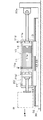
図5に示すシリンダ装置1′は、移動対象物Wを所定方向a,bに最長で前記距離Lの2/3だけ移動させるためのもので、2個のシリンダユニット10,20′が後端部を介して連結されると共に固定台30に支持される構成とされている。
A cylinder device 1 'shown in FIG. 5 is for moving a moving object W in the predetermined directions a and b by a maximum of 2/3 of the distance L.
固定台30の縦壁30a側の第1シリンダユニット10は、前記第1の実施の形態における第1シリンダユニット10と同じ構成のものであるので、詳細な説明は省略する。なお、チューブ11から突出するピストンロッド13の先端は、連結部材14を介して固定台30の縦壁30aに固設された取付部材31に連結されている。
Since the
一方、移動対象物W側の第2シリンダユニット20′は、前記第1シリンダユニット10に比較してピストンストロークが短い構成とされており、中空のチューブ21′と、該チューブ21′に摺動自在に収納され、チューブ21′内を伸張室21a′と収縮室21b′とに画成するピストン22′と、該ピストン22′に一方の端部が連結され、チューブ21′の前端側(図例では左側)から他方の端部が外部に突出するピストンロッド23′とを有している。また、前記チューブ21′の両端部に、前記伸張室21a′に開口する第1ポート21c′と前記収縮室21b′に開口する第2ポート21d′とがそれぞれ設けられている。そして、前記ピストンロッド23′の他方の端部は、作用部材24′を介して移動対象物Wに連結されている。
On the other hand, the
その場合、前記両シリンダユニット10,20′のチューブ11,21′は、後端部が結合されて一体化されている。また、前記両シリンダユニット10,20′のピストンロッド13,23′は、軸心が一致している。さらに、両シリンダユニット10,20′のピストンストロークは、それぞれ前記第1の実施の形態で説明した距離Lの1/2及び1/6とされている。
In that case, the
また、固定台30に、このシリンダ装置1′の伸縮方向つまり矢印a,b方向に沿って延びるガイドレール32が固設されており、このガイドレール32に、2個のスライダ33,33が移動自在に支持されている。そして、これらのスライダ33,33は、それぞれ前記チューブ11,21′に結合されている。
Further, a
なお、このシリンダ装置1′における圧力流体の給排システムは、前記図1で説明したと同様であるので説明を省略するが、以下の説明では同図で用いた符号をそのまま用いることにする。 The pressure fluid supply / discharge system in the cylinder device 1 'is the same as that described with reference to FIG. 1 and thus will not be described. However, in the following description, the reference numerals used in FIG.
ここで、このシリンダ装置1′の作用について説明する。 Here, the operation of the cylinder device 1 'will be described.
まず、第1のケースでは、図6に示すように、圧力流体源41からの圧縮空気が、流量調整弁43により所定流量とされて第1シリンダユニット10の第1ポート11cを介して伸張室11aに供給されると共に、収縮室11bが第2ポート11dを介して大気に連通するように、コントローラ45は電磁切換弁44の作動を制御する。なお、第2シリンダユニット20′の伸張室21a′には圧縮空気は供給されていない。
First, in the first case, as shown in FIG. 6, the compressed air from the
その結果、第1シリンダユニット10側では、第1ポート11cを介して伸張室11aに供給された圧縮空気によりピストン12つまりピストンロッド13が前進しようとする。その場合、該ピストンロッド13の先端は固定台30の縦壁30aに連結されているので、第1シリンダユニット10のチューブ11と第2シリンダユニット20′のチューブ21′とは、スライダ33,33を介してガイドレール32に支持されつつ縦壁30aとは反対方向つまり矢印a方向に、ピストンストロークである前記距離Lの1/2だけ移動し、第2シリンダユニット20′のピストンロッド23′に連結された移動対象物Wは、同じ距離だけ移動することになる。
As a result, on the
また、第2のケースでは、図7に示すように、圧力流体源41からの圧縮空気が、流量調整弁43により所定流量とされて第2シリンダユニット20′の第1ポート21c′を介して伸張室21a′に供給されると共に、収縮室21b′が第2ポート21d′を介して大気に連通するように、コントローラ45は電磁切換弁44の作動を制御する。なお、第1シリンダユニット10の伸張室11aには圧縮空気は供給されていない。
In the second case, as shown in FIG. 7, the compressed air from the
その結果、第2シリンダユニット20′側では、第1ポート21c′を介して伸張室21a′に供給された圧縮空気によりピストン22′つまりピストンロッド23′が前進する。その場合、該ピストンロッド23′の先端は移動対象物Wに連結されているので、移動対象物Wは、ピストンストロークである前記距離Lの1/6だけ矢印a方向へ移動することになる。なお、第2のケースでは、スライダ33,33を介してガイドレール32に支持された両チューブ11,21′は移動しない。
As a result, on the
そして、第3のケースでは、図8に示すように、圧力流体源41からの圧縮空気が、流量調整弁43,43により所定流量とされて両シリンダユニット10,20′の第1ポート11c,21c′を介して伸張室11a,21a′に供給されると共に、収縮室11b,21b′が第2ポート11d,21d′を介して大気に連通するように、コントローラ45は電磁切換弁44,44の作動を制御する。
In the third case, as shown in FIG. 8, the compressed air from the
すなわち、第1シリンダユニット10側では、第1ポート11cを介して伸張室11aに供給された圧縮空気によりピストン12つまりピストンロッド13が前進しようとする。その場合、該ピストンロッド13の先端は固定台30の縦壁30aに連結されているので、第1シリンダユニット10のチューブ11と第2シリンダユニット20′のチューブ21′とが、スライダ33,33を介してガイドレール32に支持されつつ縦壁30aとは反対方向つまり矢印a方向に移動することになる。
That is, on the
一方、第2シリンダユニット20′側では、第1ポート21c′を介して伸張室21a′に供給された圧縮空気によりピストン22′つまりピストンロッド23′が前進するので、該ピストンロッド23′の先端部に連結された移動対象物Wは、両シリンダユニット10,20′のピストンストロークの総和だけ、つまり前記距離Lの2/3だけ矢印a方向に移動することになり、もってこのシリンダ装置1′は伸張状態となる。
On the other hand, on the
なお、第3のケースのように伸張速度の高速化を目的とするのではなく、ピストンストロークの拡大を目的とする場合には、第1シリンダユニット10と第2シリンダユニット20′とに圧縮空気を一斉に供給するのではなく、順次供給するようにしてもよい。
When the purpose is not to increase the extension speed as in the third case but to increase the piston stroke, the compressed air is applied to the
その場合、伸張速度の高速化や伸張動作の安定化が可能となった上で、各シリンダユニット10,20′のピストンストロークがそれぞれ前記距離Lの1/2及び1/6のように互いに異なっているので、シリンダ装置1の目的に応じて多様な伸張パターンを選択することができる。例えば、第1のケースのようにピストンストロークの長いシリンダユニット10のみを作動させる場合と、第2のケースのようにピストンストロークの短いシリンダユニット20′のみを作動させる場合と、第3のケースのように両シリンダユニット10,20′を作動させる場合とで、前記距離Lの1/2、1/6、2/3のように都合3通りのピストンストロークが実現される。
In this case, the extension speed can be increased and the extension operation can be stabilized, and the piston strokes of the
次に、本考案の第3の実施の形態に係るシリンダ装置について説明する。 Next, a cylinder device according to a third embodiment of the present invention will be described.
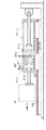
図9に示すシリンダ装置1″は、移動対象物Wを所定方向a,bに最長で前記距離Lの2/3だけ移動させるためのもので、2個のシリンダユニット10,20″が後端部を介して連結されると共に固定台30に支持される構成とされている。
The cylinder device 1 ″ shown in FIG. 9 is for moving the moving object W in the predetermined directions a and b by a maximum of 2/3 of the distance L, and two
固定台30の縦壁30a側の第1シリンダユニット10は、前記第1の実施の形態における第1シリンダユニット10と同じ構成のものであるので、詳細な説明は省略する。なお、チューブ11から突出するピストンロッド13の先端は、連結部材14を介して固定台30の縦壁30aに固設された取付部材31に連結されている。
Since the
一方、移動対象物W側の第2シリンダユニット20″は、前記第1シリンダユニット10に比較してピストン22″の受圧面積が大きく、かつ、前記第2の実施の形態における第2シリンダユニット20′と同じピストンストロークを有する構成とされており、中空のチューブ21″と、該チューブ21″に摺動自在に収納され、チューブ21″内を伸張室21a″と収縮室21b″とに画成する大径のピストン22″と、該ピストン22″に一方の端部が連結され、チューブ21″の前端側(図例では左側)から他方の端部が外部に突出するピストンロッド23″とを有している。また、前記チューブ21″の両端部に、前記伸張室21a″に開口する第1ポート21c″と前記収縮室21b″に開口する第2ポート21d″とがそれぞれ設けられている。そして、前記ピストンロッド23″の他方の端部は、作用部材24″を介して移動対象物Wに連結されている。
On the other hand, the
その場合、前記両シリンダユニット10,20″のチューブ11,21″は、後端部が結合されて一体化されている。また、前記両シリンダユニット10,20″のピストンロッド13,23″は、軸心が一致している。さらに、両シリンダユニット10,20″のピストンストロークは、それぞれ前記距離Lの1/2及び1/6とされると共に、第2シリンダユニット20″のピストン22″の受圧面積は、第1シリンダユニット10のピストン12の受圧面積のおよそ3倍に設定されている。
In this case, the
また、固定台30に、このシリンダ装置1″の伸縮方向つまり矢印a,b方向に沿って延びるガイドレール32が固設されており、このガイドレール32に、2個のスライダ33,33が移動自在に支持されている。そして、これらのスライダ33,33は、それぞれ前記チューブ11,21″に結合されている。ただし、受圧面積が異なる関係上、小径のピストン12を有する第1シリンダユニット10はスペーサ34を介してスライダ33に結合され、大径のピストン22″を有する第2シリンダユニット20″は直接スライダ33に結合されている。
In addition, a
なお、このシリンダ装置1″における圧力流体の給排システムは、前記図1で説明したと同様であるので説明を省略するが、この場合にも、以下の説明では同図で用いた符号をそのまま用いることにする。 The pressure fluid supply / discharge system in the cylinder device 1 ″ is the same as that described with reference to FIG. 1 and will not be described. In this case as well, in the following description, the reference numerals used in FIG. I will use it.
ここで、このシリンダ装置1″の作用について説明する。 Here, the operation of the cylinder device 1 ″ will be described.
図10に示すように、まず、圧力流体源41からの圧縮空気が、流量調整弁43により所定流量とされて第2シリンダユニット20″の第1ポート21c″を介して伸張室21a″に供給されると共に、収縮室21b″が第2ポート21d″を介して大気に連通するように、コントローラ45は電磁切換弁44の作動を制御する。
As shown in FIG. 10, first, the compressed air from the
その結果、第2シリンダユニット20″側では、第1ポート21c″を介して伸張室21a″に供給された圧縮空気によりピストン22″つまりピストンロッド23″が前進する。その場合、該ピストンロッド23″の先端は移動対象物Wに連結されているので、移動対象物Wは矢印a方向へ移動することになる。
As a result, on the
第2シリンダユニット20″のピストンロッド23″が前進し始めると、次いで適宜のタイミングで圧力流体源41からの圧縮空気が、流量調整弁43により所定流量とされて第1シリンダユニット10の第1ポート11cを介して伸張室11aに供給されると共に、収縮室11bが第2ポート11dを介して大気に連通するように、コントローラ45は電磁切換弁44の作動を制御する。
When the
その結果、ピストン12つまりピストンロッド13が前進しようとすることにより第1シリンダユニット10のチューブ11と第2シリンダユニット20″のチューブ21″とが、スライダ33,33を介してガイドレール32に支持されつつ固定台30の縦壁30aとは反対方向つまり矢印a方向に移動し、これに加えて第2シリンダユニット20″のピストンロッド23″の前進により、移動対象物Wは前記距離Lの2/3だけ矢印a方向に移動するようになる。
As a result, the
その場合、伸張速度の高速化と伸張動作の安定化とが可能となった上で、各シリンダユニット10,20″のピストン12,22″の受圧面積が互いに異なっているので、シリンダ装置1″の目的に応じて適切な推力を選択することができる。すなわち、シリンダ装置1″の起動時には一般に大きな推力が必要とされることから、まず大きな推力を得るべく受圧面積の大きいピストン22″を有する第2シリンダユニット20″を作動させ、次いで受圧面積の小さいピストン12を有する第1シリンダユニット10を作動させることにより、対象物Wの速やかな移動が可能となる。
In that case, since the extension speed can be increased and the extension operation can be stabilized, the pressure receiving areas of the
なお、本考案は、具体的に詳述した前記実施の形態に限定されることはなく、本考案の趣旨に沿うものであればよい。例えば、加圧流体には、圧縮空気の他に油圧や水圧が適用される。 In addition, this invention is not limited to the said embodiment specifically explained in detail, What is necessary is just in line with the meaning of this invention. For example, hydraulic pressure or water pressure is applied to the pressurized fluid in addition to compressed air.
以上説明したように、本考案によれば、2個のシリンダユニットを使用した簡素化された構成で、伸張速度の高速化と伸張動作の安定化とが可能なシリンダ装置が提供される。すなわち、本考案は、流体圧シリンダ装置の技術分野に広く好適である。 As described above, according to the present invention, there is provided a cylinder device capable of increasing the extension speed and stabilizing the extension operation with a simplified configuration using two cylinder units. That is, the present invention is widely suitable for the technical field of fluid pressure cylinder devices.
1,1′,1″ シリンダ装置
10 第1シリンダユニット
11 チューブ
11a 伸張室
11b 収縮室
12 ピストン
13 ピストンロッド
20,20′,20″ 第2シリンダユニット
21,21′,21″ チューブ
21a,21a′,21a″ 伸張室
21b,21b′,21b″ 収縮室
22,22′,22″ ピストン
23,23′,23″ ピストンロッド
30a 縦壁(固定部材)
32 ガイドレール(ガイド機構)
33 スライダ(ガイド機構)
1, 1 ', 1 "
32 Guide rail (guide mechanism)
33 Slider (guide mechanism)
Claims (3)
前記両シリンダユニットのチューブが、軸心を一致させた状態で、後端部を結合することにより一体化されていると共に、
この一体化チューブを軸心方向に移動自在に支持するガイド機構と、
一方のユニットのピストンロッドの先端が連結された固定部材とを有することを特徴とするシリンダ装置。 A cylinder tube; a piston slidably accommodated in the tube; and a piston that defines the inside of the tube as an expansion chamber and a contraction chamber; and a piston rod that is connected to the piston and projects outward from the front end side of the tube A cylinder device having two cylinder units,
The tubes of both cylinder units are integrated by joining the rear ends in a state where the axes are aligned,
A guide mechanism for supporting the integrated tube movably in the axial direction;
A cylinder device comprising: a fixing member to which a tip of a piston rod of one unit is coupled.
前記各シリンダユニットは、ピストンストロークが互いに異なっていることを特徴とするシリンダ装置。 The cylinder device according to claim 1,
Each cylinder unit is different in piston stroke from each other.
前記各シリンダユニットは、ピストンの受圧面積が互いに異なっていることを特徴とするシリンダ装置。 In the cylinder device according to claim 1 or 2,
Each cylinder unit has a piston pressure-receiving area different from each other.
Priority Applications (1)
| Application Number | Priority Date | Filing Date | Title |
|---|---|---|---|
| JP2005005558U JP3114709U (en) | 2005-07-14 | 2005-07-14 | Cylinder device |
Applications Claiming Priority (1)
| Application Number | Priority Date | Filing Date | Title |
|---|---|---|---|
| JP2005005558U JP3114709U (en) | 2005-07-14 | 2005-07-14 | Cylinder device |
Publications (1)
| Publication Number | Publication Date |
|---|---|
| JP3114709U true JP3114709U (en) | 2005-10-27 |
Family
ID=43277005
Family Applications (1)
| Application Number | Title | Priority Date | Filing Date |
|---|---|---|---|
| JP2005005558U Expired - Fee Related JP3114709U (en) | 2005-07-14 | 2005-07-14 | Cylinder device |
Country Status (1)
| Country | Link |
|---|---|
| JP (1) | JP3114709U (en) |
Cited By (2)
| Publication number | Priority date | Publication date | Assignee | Title |
|---|---|---|---|---|
| JP2607085Y2 (en) | 1993-06-16 | 2001-03-19 | 三菱樹脂株式会社 | Plastic bottle with panel |
| JP2011195068A (en) * | 2010-03-23 | 2011-10-06 | Nippon Lift Kk | Underfloor-stored lifting apparatus |
-
2005
- 2005-07-14 JP JP2005005558U patent/JP3114709U/en not_active Expired - Fee Related
Cited By (2)
| Publication number | Priority date | Publication date | Assignee | Title |
|---|---|---|---|---|
| JP2607085Y2 (en) | 1993-06-16 | 2001-03-19 | 三菱樹脂株式会社 | Plastic bottle with panel |
| JP2011195068A (en) * | 2010-03-23 | 2011-10-06 | Nippon Lift Kk | Underfloor-stored lifting apparatus |
Similar Documents
| Publication | Publication Date | Title |
|---|---|---|
| US6408740B1 (en) | Three position cylinder | |
| JP2007521907A5 (en) | ||
| JP2000087913A (en) | Nesting device with multi-stage telescopic cylinder | |
| CN105836637B (en) | The telescopic device of telescopic arm | |
| JP2008249027A (en) | Double-acting air cylinder positioning control mechanism | |
| CN112343874B (en) | Fluid return device for double-acting pneumatic cylinder and method for operating the cylinder | |
| US11261885B2 (en) | Fluid pressure cylinder | |
| CN110573750B (en) | Supercharging device and cylinder device having the same | |
| JP2009030652A (en) | Multistage telescopic drive device | |
| CN1963239B (en) | Cylinder set for use in retraction mechanism | |
| JP6638882B2 (en) | Telescopic mechanism | |
| JP2009250252A (en) | Hydraulic cylinder device | |
| JPH11139765A (en) | Boom telescopic control circuit of hydraulic crane | |
| KR200444599Y1 (en) | Cylinder with differential function | |
| CN116753209B (en) | Buffer multistage servo hydraulic cylinder | |
| JP2955220B2 (en) | In-line pressure booster | |
| CN116199143B (en) | Single-cylinder pin telescopic system and control method | |
| CN111442006B (en) | A multi-cylinder sequential telescopic hydraulic system for a folding arm truck crane | |
| KR0179648B1 (en) | Sequential actuating hydraulic cylinder of straight boom crane | |
| US9699973B2 (en) | Pneumatically powered pole saw | |
| GB2595121A (en) | A fluid-driven linear motor | |
| CN223754352U (en) | A hydraulic station | |
| JP2003278713A (en) | Drive | |
| JP2002213403A (en) | Sequential operation cylinder system | |
| JPH04254007A (en) | Two-stage expansion lock actuator |
Legal Events
| Date | Code | Title | Description |
|---|---|---|---|
| R150 | Certificate of patent or registration of utility model |
Free format text: JAPANESE INTERMEDIATE CODE: R150 |
|
| FPAY | Renewal fee payment (event date is renewal date of database) |
Free format text: PAYMENT UNTIL: 20090831 Year of fee payment: 4 |
|
| FPAY | Renewal fee payment (event date is renewal date of database) |
Free format text: PAYMENT UNTIL: 20090831 Year of fee payment: 4 |
|
| FPAY | Renewal fee payment (event date is renewal date of database) |
Free format text: PAYMENT UNTIL: 20100831 Year of fee payment: 5 |
|
| LAPS | Cancellation because of no payment of annual fees |