JP3122000U - Support structure for supporting column on waterproof layer and fixing device for supporting column used for the structure - Google Patents
Support structure for supporting column on waterproof layer and fixing device for supporting column used for the structure Download PDFInfo
- Publication number
- JP3122000U JP3122000U JP2006001827U JP2006001827U JP3122000U JP 3122000 U JP3122000 U JP 3122000U JP 2006001827 U JP2006001827 U JP 2006001827U JP 2006001827 U JP2006001827 U JP 2006001827U JP 3122000 U JP3122000 U JP 3122000U
- Authority
- JP
- Japan
- Prior art keywords
- support
- waterproof layer
- fixing
- receiving portion
- end receiving
- Prior art date
- Legal status (The legal status is an assumption and is not a legal conclusion. Google has not performed a legal analysis and makes no representation as to the accuracy of the status listed.)
- Expired - Fee Related
Links
Images


Landscapes
- Building Environments (AREA)
Abstract
【課題】既存防水層上に屋上緑化装置等に植え付けた樹木などの支柱端部を、必要に応じた所望の位置で簡単容易に連結固定でき、しかも防水性能毀損の恐れがなく、しかも既存防水層上にさらに新規な防水層を重畳する手法による防水層補修工事を容易にする。
【解決手段】下地と、この表面に形成される防水層と、この防水層上に設けられる支柱等固定装置と、前記支柱等固定装置を防水層上に固定する固着手段とからなり、前記支柱等固定装置は、支柱端受け部とこの支柱端受け部に立設される1以上の支持体を具え、支持体にはロープ、針金その他を係止するための複数の係合手段を形成してなる防水層上における支柱等固定構造を実現して、上記の課題を解決する。
【選択図】 図2An object of the present invention is to easily connect and fix the end of a pillar such as a tree planted on a rooftop greening device on an existing waterproof layer at a desired position according to need, and there is no risk of damage to waterproof performance. The waterproof layer repair work by the method of superimposing a new waterproof layer on the layer is facilitated.
The strut includes a base, a waterproof layer formed on the surface, a support device such as a support provided on the waterproof layer, and a fixing means for fixing the support device such as the support on the waterproof layer. The equi-fixing device includes a column end receiving portion and one or more supports erected on the column end receiving portion, and the support includes a plurality of engaging means for locking ropes, wires, and the like. The above-described problem is solved by realizing a fixing structure such as a support on the waterproof layer.
[Selection] Figure 2
Description
本願考案は、屋上、陸屋根等の既存防水層上に樹木、手摺その他各種の構築物の設置に際してそれらの支持支柱等を固定する技術に関し、詳しくは防水層に介在することなく本来の防水性を維持し支柱端を強固に固定できる新規な固定技術に関するものである。 The present invention relates to a technology for fixing supporting pillars and the like when installing trees, handrails and other various structures on an existing waterproof layer such as a rooftop or a flat roof. Specifically, the original waterproof property is maintained without being interposed in the waterproof layer. The present invention relates to a novel fixing technology that can firmly fix the ends of the support columns.
建築物の屋上、陸屋根、バルコニー等に敷設した既存の防水層上に、屋上緑化装置等を敷設してヒートアイランド現象を抑制し、併せて景観の向上に資する試みがなされている。
屋上緑化装置では、樹木等比較的高さのある植物を植え付ける場合、土壌部分が浅いこと、高所では常に風が吹いている等の事情から、根が定着するまでこれを安定的に支える必要があり、一般に支柱を設置することになる。
Attempts have been made to suppress the heat island phenomenon by laying a rooftop greening device on the existing waterproof layer laid on the rooftop, flat roof, balcony, etc. of the building, and to contribute to the improvement of the landscape.
When planting trees with relatively high height, such as trees, it is necessary to stably support this until the roots are established due to the fact that the soil is shallow and the wind is always blowing at high places. In general, a column will be installed.
このような支柱の一端は樹木に締結固定され、他端は既存の防水層上に固定することになる。 しかしながら、防水層上に支柱端を固定する支点、拠点等を後付けすることは既存防水層になんらか手を加えることになるから防水性になんらかの影響を及ぼす恐れなくこれをなすことは難しい。 One end of such a column is fastened and fixed to the tree, and the other end is fixed on the existing waterproof layer. However, retrofitting a fulcrum, base, etc. for fixing the end of the column on the waterproof layer adds some work to the existing waterproof layer, and it is difficult to do this without any influence on the waterproof property.
このため、従来はこのような前記支点あるいは拠点としての架台と呼ばれるものを防水層の施工前に下地に連結固定したうえで防水層の形成をなすようにして、防水層に手を加えることを回避し防水信頼性を確保するようにしている。 For this reason, conventionally, such a fulcrum or a base as a base is connected and fixed to the base before construction of the waterproof layer, and then the waterproof layer is formed, and the waterproof layer is modified. It avoids and ensures waterproof reliability.
すなわち、防水層の施工後に架台を設置しようとすれば、防水層を通して下地コンクリート等にアンカーボルトを打ち込みこれによって架台を固定しなければならない。ところが、既存防水層を通して下地にアンカーボルト等を打ち込むことは、事実上は非常に困難である。その理由は、従来から既存の防水層にいかなる形態でも孔を穿つことは防水信頼性を損なう惧れから禁忌事項とされているからである。したがって、従来は防水層上に前記架台が必要とされる場合は、防水層の形成前に下地上に設置固定しこれらを含めて防水層を被装する方法がとられている。 このため設置場所の自由性がなく、必要な場所に設置することができなかった。また、このような架台を設置は、既存防水層の上にさらに防水層を張設する手法による防水層補修工事を施工することを難しくしている。 That is, if it is going to install a mount after construction of a waterproof layer, an anchor bolt must be driven in concrete foundation etc. through a waterproof layer, and this must be fixed. However, it is actually very difficult to drive anchor bolts or the like into the base through the existing waterproof layer. The reason for this is that it has been conventionally contraindicated to perforate holes in any form in the existing waterproof layer because it may impair the waterproof reliability. Therefore, conventionally, when the mount is required on the waterproof layer, a method of installing and fixing the waterproof layer including these on the base before the waterproof layer is formed is used. For this reason, there was no freedom of installation location, and it was not possible to install it where it was necessary. In addition, the installation of such a gantry makes it difficult to perform waterproof layer repair work by a method of further stretching a waterproof layer on the existing waterproof layer.
なお、本願考案に関連する一般的技術として次の文献が開示されている。
本願考案が解決しようとする課題は次の通りである。
(1)既存防水層上に屋上緑化装置等に植え付けた樹木などの支柱端部を、必要に応じた所望の位置で簡単容易に連結固定でき、しかも防水性能毀損の恐れが生じないこと。
(2)既存防水層上にさらに新規な防水層を重畳する手法による防水層補修工事を容易にすること。
The problems to be solved by the present invention are as follows.
(1) The end of a pillar such as a tree planted in a rooftop greening device or the like on an existing waterproofing layer can be easily connected and fixed at a desired position as necessary, and there is no risk of damage to waterproof performance.
(2) To facilitate repair work of the waterproof layer by a method of superimposing a new waterproof layer on the existing waterproof layer.
本願考案は、下地と、この表面に形成される防水層と、この防水層上に設けられる支柱等固定装置と、前記支柱等固定装置を防水層上に固定する固着手段とからなり、前記支柱等固定装置は、支柱端受け部とこの支柱端受け部に立設される1以上の支持体を具え、支持体にはロープ、針金その他を係止するための複数の係合手段を形成してなる防水層上における支柱等固定構造を実現して、上記従来の課題を解決する。 The present invention comprises a base, a waterproof layer formed on the surface, a support device such as a support provided on the waterproof layer, and a fixing means for fixing the support device such as the support on the waterproof layer. The equi-fixing device includes a strut end receiving portion and one or more supports standing on the strut end receiving portion, and the support forms a plurality of engaging means for locking ropes, wires, and the like. A fixing structure such as a support on the waterproof layer is realized to solve the conventional problem.
また、上記の支柱等固定構造において、前記支柱等固定装置の前記支持体は前記支柱端受け部上に立設される板状体で構成し、この板状体に形成される複数の孔部で前記係合手段を構成することがある。 Further, in the above-mentioned fixing structure for the support column, the support body of the fixing device for the support column is configured by a plate-like body standing on the support end receiving portion, and a plurality of holes formed in the plate-like body In some cases, the engaging means may be configured.
さらに、上記の支柱等固定構造において、前記支柱端受け部上に立設される板状体は一対の各板状体が互いに交差するように形成することがある。 Furthermore, in the above-described fixing structure such as a support, the plate-like body standing on the support end receiving portion may be formed such that a pair of plate-like bodies intersect each other.
またさらに、上記いずれかの支柱等固定構造において、支柱等固定装置を防水層上に固定するための前記固着手段は、支柱端受け部と防水層との間に介装される接着層となすことがある。 Furthermore, in any one of the above-described fixing structures for the support columns, the fixing means for fixing the fixing device for the support columns on the waterproof layer is an adhesive layer interposed between the support end receiving portion and the waterproof layer. Sometimes.
本願考案はまた、防水層上に設けられて各種の支柱等の端部を固定する支柱等固定装置であって、支柱端受け部とこの支柱端受け部に立設される1以上の支持体を具え、支持体にはロープ、針金その他を係止するための複数の係合手段を形成してなる防水層上における支柱等固定装置を提供して上記課題を解決しようとするものである。 The present invention is also a support device for fixing a pillar, which is provided on a waterproof layer and fixes an end portion of various pillars, etc., and is provided with a pillar end receiving portion and one or more supports standing on the pillar end receiving portion. And a support device such as a support on a waterproof layer in which a support is formed with a plurality of engaging means for locking ropes, wires, and the like.
また、上記の支柱等固定装置において、前記支持体は前記支柱端受け部上に立設される板状体で構成し、この側壁に形成される複数の孔部で前記係合手段を構成することがある。 Further, in the above-described fixing device such as a column, the support body is constituted by a plate-like body standing on the column end receiving portion, and the engagement means is constituted by a plurality of holes formed in the side wall. Sometimes.
さらに、上記の支柱等固定装置において、前記支柱端受け部上に立設される板状体は一対の各板状体が互いに交差するように設ける構成と為すことがある。 Furthermore, in the above-described fixing device such as a column, the plate-like body standing on the column end receiving portion may be provided so that a pair of plate-like bodies intersect each other.
支柱等固定装置において、支柱端受け部は亜鉛メッキ鉄材で構成し、形状は方形が好ましい。 支柱端受け部に立設される支持体が単数の場合は、1枚の前記亜鉛メッキ鉄材を直角に折り曲げて、それぞれ支柱端受け部、支持体とする。立設される支持体には係合手段としてのそれぞれ径の異なる孔部を複数形成する。孔部の形成位置はランダムになし、なるべく支持体全面に拡散するように展開する。 In the fixing device such as a support, the support end receiving portion is made of a galvanized iron material, and the shape is preferably rectangular. When there is a single support body standing on the column end receiving portion, one piece of the galvanized iron material is bent at a right angle to form a column end receiving portion and a support body, respectively. A plurality of holes having different diameters as engaging means are formed in the support body that is erected. The positions where the holes are formed are random, and the holes are spread so as to be diffused over the entire surface of the support.
また、支柱端受け部に立設される支持体は、複数設けてもよい。この場合、複数の支持体は、同じ高さ、あるいは異なる高さの板状体を並列に設置してもよい。 あるいは、2枚の板状体を互いの中心部で交差するように設置することも可能である。 Moreover, you may provide multiple support bodies standingly arranged in a support | pillar end receiving part. In this case, the plurality of supports may be arranged in parallel with plate-like bodies having the same height or different heights. Alternatively, it is possible to install two plate-like bodies so as to intersect each other at the center.
支持体に設ける係合手段は前記孔部に替えて、多数の突起を設けてもよく、あるいは板状体の上端縁、側端縁に形成した多数のスリットにより構成することもある。 The engaging means provided on the support may be provided with a large number of protrusions instead of the hole, or may be constituted by a large number of slits formed at the upper edge and the side edge of the plate-like body.
支柱端受け部の防水層への固定をなす固着手段は、作業性等の見地から両面接着テープによるのが好ましい。 The fixing means for fixing the column end receiving portion to the waterproof layer is preferably a double-sided adhesive tape from the viewpoint of workability and the like.
支柱端の固定は以下のような作業手順で行うことになる。 すなわち、支柱端を支柱端受け部に載置し、支柱の側端部を支持体に当接させる。次いで、針金類で支柱を係合手段を介して支持体に緊縛固定する。 支柱は、場合により様々な角度を有しているが、係合手段としての孔部は支持体の全面に拡散形成されているから支柱がいかなる角度にあろうともこれを針金等で所望どおり自在に緊縛固定することができる。 Fixing of the column end is performed by the following work procedure. That is, the column end is placed on the column end receiving portion, and the side end portion of the column is brought into contact with the support. Next, the strut is tightly fixed to the support body with the wire through the engaging means. The struts have various angles depending on the case, but since the hole as the engaging means is diffused and formed on the entire surface of the support body, it can be freely adjusted as desired with a wire or the like regardless of the angle of the struts. Can be tightly fixed.
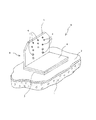
図面に基づいて本願考案の1実施例を説明する。 図1は、本願考案に係る支柱等固定構造の一実施例を示す一部切欠斜視図である。支柱等固定構造Aは、コンクリート下地1と、この表面に形成される防水層2と、この防水層2上に設けられる支柱等固定装置Bと、前記支柱等固定装置Bを防水層2上に固定する固着手段としての両面接着テープ3からなり、前記支柱等固定装置Bは、支柱端受け部4とこの支柱端受け部4に立設される支持体としての板状体5を具え、支持体としての前記板状体5にはロープ、針金その他を係止するための係合手段としての複数の孔部6が形成されている。
An embodiment of the present invention will be described with reference to the drawings. FIG. 1 is a partially cutaway perspective view showing an embodiment of a fixing structure such as a post according to the present invention. The fixing structure A such as a post includes a
この実施例において、支柱等固定装置Bを構成する支柱端受け部4と支持体としての板状体5とは亜鉛メッキ鉄板を折り曲げることにより形成されている。この結果、支持体としての板状体5は支柱端受け部4の一方の側端縁に位置している。
In this embodiment, the column
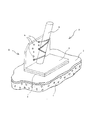
図2は、上記の支柱等固定構造Aにおける、支柱端の固定例を示す斜視図である。植培装置における樹木(いずれも不図示)に設けられた支柱Sはその下端部が支柱端受け部4に支持され、支柱Sの側部は支持体としての板状体5面に当接されている。 この状態で、支柱Sの前記当接部分は係合手段としての孔部6を利用して緊縛・固定されている。 すなわち、支柱Sの当接部分には孔部6、6,6を介して針金7が巻回されて強固に固定されている。
FIG. 2 is a perspective view showing an example of fixing a column end in the column fixing structure A described above. The lower end of the column S provided on the tree (not shown) in the planting device is supported by the column
図3は、支柱等固定装置Bの第2実施例を示す斜視図である。この実施例では、支柱端受け部4の両側端に支持体としての板状体5が形成されている。支柱端受け部4とその両側端の支持体としての一対の板状体5,5は一体に形成されていて、この実施例では一枚板の亜鉛メッキ鉄板を折り曲げることにより成形されている。
FIG. 3 is a perspective view showing a second embodiment of the fixing device B such as a column. In this embodiment, plate-
図4は、支柱等固定装置Bの第3実施例を示す斜視図である。この実施例では、支柱端受け部4の中央部分に支持体としての板状体5が形成されており、ロープ、針金その他を係止するための係合手段は、上記の孔部6に替えて、板状体5の壁面に形成されたビス状突起6aと板状体5の端縁部に形成されるスリット群6bにより構成されている。これらビス状突起6aとスリット6bにロープ、針金その他を係止することにより支柱等を強固自在に緊縛・固定することができる。ビス状突起6aは、場合によっては孔部6より針金等の係止作業をよりスムーズに行い得る。
FIG. 4 is a perspective view showing a third embodiment of the fixing device B such as a column. In this embodiment, a plate-
図5は、支柱等固定装置Bの第4実施例を示す斜視図である。この実施例では、支柱端受け部4の中央部分に、支持体としての板状体5が互いの中心部で交差するように一対設置されている。 ロープ、針金その他を係止するための係合手段は、上記の孔部6、ビス状突起6a、スリット群6bにより構成されている。このように、係合手段を各種機能を異にするもので構成することにより様々な状況に対応して支柱等の緊縛・固定をようになすことができる。
FIG. 5 is a perspective view showing a fourth embodiment of the fixing device B such as a column. In this embodiment, a pair of plate-
本願に係る支柱等固定装置は、既存防水層上の任意の位置に自由に設置できるので屋上等における構築物の配置設定の自由度が大幅に向上し屋上の有効利用が促進される。
さらに、本願考案に係る支柱等固定技術は既存防水層の上にさらに新規な防水層を重設する手法による改修工事にも効果を有する。 すなわち、既存防水層上に新たに補修防水層を全面的に張設する場合、装置を取り外したうえで、新規防水層を張設する。 そして、この新たな既存防水層上にふたたび支柱等固定装置を簡単にしかも高い防水信頼性の下に形成することができる。
Since the fixing device such as the support according to the present application can be freely installed at an arbitrary position on the existing waterproof layer, the degree of freedom of arrangement setting of the structure on the rooftop or the like is greatly improved, and the effective use of the rooftop is promoted.
Further, the fixing technology for the support according to the present invention is also effective for the renovation work by a method in which a new waterproof layer is superimposed on the existing waterproof layer. That is, when a repair waterproof layer is newly stretched over the entire existing waterproof layer, the new waterproof layer is stretched after removing the device. Then, a fixing device such as a support can be easily formed on the new existing waterproof layer with high waterproof reliability.
A.........支柱等固定構造
B.........支柱等固定装置
S.........支柱
1.........コンクリート下地
2.........防水層
3.........固定手段(両面接着テープ)
4.........支柱端受け部
5.........支持体(板状体)
6.........係合手段(孔部)
6a........係合手段(ビス状突起)
6b........係合手段(スリット)
A. . . . . . . . . Fixing structure such as strut B. . . . . . . . . Fixing device for struts etc. . . . . . . . .
3. . . . . . . . . Fixing means (double-sided adhesive tape)
4). . . . . . . . . 4. Column end receiving part . . . . . . . . Support (plate-like body)
6). . . . . . . . . Engaging means (hole)
6a. . . . . . . . Engagement means (screw projection)
6b. . . . . . . . Engagement means (slit)
Claims (7)
Priority Applications (1)
| Application Number | Priority Date | Filing Date | Title |
|---|---|---|---|
| JP2006001827U JP3122000U (en) | 2006-03-14 | 2006-03-14 | Support structure for supporting column on waterproof layer and fixing device for supporting column used for the structure |
Applications Claiming Priority (1)
| Application Number | Priority Date | Filing Date | Title |
|---|---|---|---|
| JP2006001827U JP3122000U (en) | 2006-03-14 | 2006-03-14 | Support structure for supporting column on waterproof layer and fixing device for supporting column used for the structure |
Publications (1)
| Publication Number | Publication Date |
|---|---|
| JP3122000U true JP3122000U (en) | 2006-06-01 |
Family
ID=43472082
Family Applications (1)
| Application Number | Title | Priority Date | Filing Date |
|---|---|---|---|
| JP2006001827U Expired - Fee Related JP3122000U (en) | 2006-03-14 | 2006-03-14 | Support structure for supporting column on waterproof layer and fixing device for supporting column used for the structure |
Country Status (1)
| Country | Link |
|---|---|
| JP (1) | JP3122000U (en) |
-
2006
- 2006-03-14 JP JP2006001827U patent/JP3122000U/en not_active Expired - Fee Related
Similar Documents
| Publication | Publication Date | Title |
|---|---|---|
| US10815667B2 (en) | Apparatus and methods for a noninvasive roof attachment system with vertical members | |
| US7484334B1 (en) | Roof anchoring kit and method | |
| EP1668199A1 (en) | Device and method for securing an insulation board within a cavity wall | |
| JP5368749B2 (en) | Rooftop greening equipment | |
| JP3122078U (en) | Fixing structure for columns on rooftops, flat roofs, etc. and fixing devices for columns used for this | |
| JP4870241B1 (en) | Photovoltaic panel mounting structure | |
| JP5890662B2 (en) | Roof construction | |
| JP7046560B2 (en) | Termination holder | |
| JP3122950U (en) | Support and fixing structure on rooftop, flat roof, etc. and support device used therefor | |
| JP3123840U (en) | Structure fixing structure on the ground or the waterproof layer thereon and the structure fixing device used therefor | |
| JP3207708U (en) | Building structure fixing device | |
| JP6621035B2 (en) | Snowfall prevention device | |
| JP3209664U (en) | Roof material | |
| JP4920263B2 (en) | A planting structure on the rooftop or roof and a device for pulling plants such as trees used for this. | |
| JP2013238008A (en) | Ridge structure of tiled roof | |
| JP3253311U (en) | Fence auxiliary fixing device | |
| JP2007291814A (en) | Rooftop installation device | |
| KR102793409B1 (en) | Supporting apparatus for rebar and insulaing material structure using the same | |
| JP6171231B2 (en) | Building tile installation structure | |
| JPH10252950A (en) | Piping device, and its cover holder | |
| JP2007209293A5 (en) | ||
| JP7419197B2 (en) | Manufacturing method of frame structure | |
| JP4573384B2 (en) | Mounting structure for rooftop installations | |
| JP2000080760A (en) | Ridge tile supporting member and ridge tile | |
| JP2012172493A (en) | Standing seam folded-plate roof structure with top face made to be flat surface |
Legal Events
| Date | Code | Title | Description |
|---|---|---|---|
| R150 | Certificate of patent or registration of utility model |
Free format text: JAPANESE INTERMEDIATE CODE: R150 |
|
| FPAY | Renewal fee payment (event date is renewal date of database) |
Free format text: PAYMENT UNTIL: 20100510 Year of fee payment: 4 |
|
| FPAY | Renewal fee payment (event date is renewal date of database) |
Free format text: PAYMENT UNTIL: 20100510 Year of fee payment: 4 |
|
| FPAY | Renewal fee payment (event date is renewal date of database) |
Free format text: PAYMENT UNTIL: 20110510 Year of fee payment: 5 |
|
| FPAY | Renewal fee payment (event date is renewal date of database) |
Free format text: PAYMENT UNTIL: 20120510 Year of fee payment: 6 |
|
| FPAY | Renewal fee payment (event date is renewal date of database) |
Free format text: PAYMENT UNTIL: 20130510 Year of fee payment: 7 |
|
| FPAY | Renewal fee payment (event date is renewal date of database) |
Free format text: PAYMENT UNTIL: 20140510 Year of fee payment: 8 |
|
| LAPS | Cancellation because of no payment of annual fees |