JP3127044U - Golf marker holder - Google Patents
Golf marker holder Download PDFInfo
- Publication number
- JP3127044U JP3127044U JP2006007263U JP2006007263U JP3127044U JP 3127044 U JP3127044 U JP 3127044U JP 2006007263 U JP2006007263 U JP 2006007263U JP 2006007263 U JP2006007263 U JP 2006007263U JP 3127044 U JP3127044 U JP 3127044U
- Authority
- JP
- Japan
- Prior art keywords
- substrate
- presser
- end side
- attached
- golf
- Prior art date
- Legal status (The legal status is an assumption and is not a legal conclusion. Google has not performed a legal analysis and makes no representation as to the accuracy of the status listed.)
- Expired - Lifetime
Links
- 239000003550 marker Substances 0.000 title claims abstract description 97
- 239000000758 substrate Substances 0.000 claims description 100
- 238000003780 insertion Methods 0.000 claims description 36
- 230000037431 insertion Effects 0.000 claims description 36
- XUIMIQQOPSSXEZ-UHFFFAOYSA-N Silicon Chemical compound [Si] XUIMIQQOPSSXEZ-UHFFFAOYSA-N 0.000 claims description 14
- 229910052710 silicon Inorganic materials 0.000 claims description 14
- 239000010703 silicon Substances 0.000 claims description 14
- 238000013459 approach Methods 0.000 claims description 12
- 230000000630 rising effect Effects 0.000 description 4
- 230000000694 effects Effects 0.000 description 3
- 239000000463 material Substances 0.000 description 3
- 238000005452 bending Methods 0.000 description 2
- 239000007779 soft material Substances 0.000 description 2
- 238000003466 welding Methods 0.000 description 2
- 238000010586 diagram Methods 0.000 description 1
- 230000005489 elastic deformation Effects 0.000 description 1
- 239000000696 magnetic material Substances 0.000 description 1
Images




Landscapes
- Footwear And Its Accessory, Manufacturing Method And Apparatuses (AREA)
Abstract
【課題】
薄手の被取付部材であっても、厚手の被取付部材であっても、被取付部材に確固として取り付けできるようにしたゴルフ用マーカー保持具を提供する。
【解決手段】
ゴルフ用マーカーMを保持するゴルフ用マーカー保持部2にサスペンダクリップ型のクリップ部3を備えたことを特徴とするものである。
【選択図】 図1【Task】
Provided is a golf marker holder that can be securely attached to a member to be attached, whether it is a thin attached member or a thick attached member.
[Solution]
The golf marker holding portion 2 for holding the golf marker M is provided with a suspender clip type clip portion 3.
[Selection] Figure 1
Description
本考案は、グリーン上のボールの位置を記憶しておくためのゴルフ用マーカーを保持するゴルフ用マーカー保持具に関するものである。 The present invention relates to a golf marker holder for holding a golf marker for storing the position of a ball on a green.
この種のゴルフ用マーカーは、ゴルフ用マーカー保持具に保持されることが可能に形成されているものであって、当該ゴルフ用マーカー保持具は、帽子の鍔等を挟持するようにして該鍔等に取り付けられるように形成されている。 This type of golf marker is formed so as to be held by a golf marker holder, and the golf marker holder is configured to hold the collar of a hat or the like. It is formed so that it may be attached to etc.
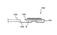
図9は、特許文献1に記載されているゴルフ用マーカー保持具を示す。
当該文献1に記載のゴルフ用マーカー保持具100は、一枚の板材を折曲部101において、U字状に折り曲げることで互いに対向するように形成された一対の挟持部102、102の間の隙間Sに被取付部材103を差し込むようにして該被取付部材103に取付られるものである。
The
しかし、前述のゴルフ用マーカー保持具100においては、当該保持具100の隙間Sに、厚手の被取付部材103を差し込むべく、該隙間Sを広げるように変形させて、厚手の被取付部材103に該保持具100を取り付けた後にあっては、当該隙間Sに薄手の被取付部材103を差し込んで、薄手の被取付部材103に該ゴルフ用マーカー保持具100を取り付けようとしても、該薄手の被取付部材103を挟持する力が弱まってしまって、該ゴルフ用マーカー保持具100を薄手の被取付部材103、例えば、シャツ等に確固として取り付けることができないことがあるという問題があった。
However, in the
本考案は、前記背景技術の問題に鑑みてなされたもので、その目的は、薄手の被取付部材であっても、厚手の被取付部材であっても、被取付部材に確固として取り付けできるようにしたゴルフ用マーカー保持具を提供することを目的とするものである。 The present invention has been made in view of the problems of the background art described above, and the purpose of the present invention is to be able to firmly attach to a mounted member, whether it is a thin mounted member or a thick mounted member. It is an object of the present invention to provide a golf marker holder.
請求項1に記載の考案は、ゴルフ用マーカーを保持するゴルフ用マーカー保持部にサスペンダクリップ型のクリップ部を設け、該クリップ部によって帽子、衣服などの被取付部材をクリップするようにして該被取付部材に取り付けられるようにしたゴルフ用マーカー保持具であって、
前記クリップ部は、基板と、該基板に回転自在に設けられた外押さえとを備え、該外押さえを基板に対して閉位置に保持して被取付部材をクリップする一方、該外押さえを開位置に保持して被取付部材を開放し、
前記マーカー保持部は、前記基板又は外押さえに取り付けられることを特徴とするものである。
According to the first aspect of the present invention, a suspender clip-type clip portion is provided on a golf marker holding portion for holding a golf marker, and the attached member such as a hat or clothing is clipped by the clip portion. A golf marker holder that can be attached to an attachment member,
The clip portion includes a substrate and an outer presser rotatably provided on the substrate, holds the outer presser in a closed position with respect to the substrate and clips the attached member, while opening the outer presser. Hold the position to release the mounted member,
The marker holding part is attached to the substrate or the outer presser.
請求項2に記載の考案は、ゴルフ用マーカーを保持するゴルフ用マーカー保持部にクリップ部を備え、該クリップ部によって被取付部材に着脱自在に取り付けられるようにしたゴルフ用マーカー保持具であって、
前記クリップ部は、基板と、内押さえと、外押さえとを備え、
前記内押さえは、その先端側が前記基板に対して接近又は離間する方向のバネ力が付与された状態でその基端が前記基板に支持され、且つ、その先端側が前記基板に対して閉塞又は接近可能な挟持端となって該挟持端と基板との間に被取付部材が挿入されて挟持される挿入口が形成され、
前記外押さえは、基端側が押圧部になると共に先端側が操作部となり、
前記外押さえは、前記内押さえの外側において前記基板に回転自在に設けられ、該回転に伴って、前記押圧部が前記外押さえの回転中心よりも基端側で前記内押さえの上面に当接することにより、前記操作部は前記挿入口を閉塞する方向のバネ力が前記内押さえから付与されて、前記挿入口の閉状態を維持し、一方、前記押圧部が前記外押さえの回転中心よりも先端側で前記内押さえの上面に当接することにより前記操作部は前記挿入口を開放する方向のバネ力が前記内押さえから付与されて、前記挿入口の開状態を維持し、
前記操作部が操作されることで、前記押圧部が前記内押さえに当接する位置を変更させることによって、前記挿入口の閉状態と開状態とを変更させ、
前記マーカー保持部は、前記基板又は外押さえに取り付けられることを特徴とするものである。
The invention according to
The clip portion includes a substrate, an inner presser, and an outer presser,
The inner presser is supported by the substrate with a spring force applied in a direction in which the tip side approaches or separates from the substrate, and the tip side closes or approaches the substrate. An insertion port is formed in which a mounting member is inserted and sandwiched between the sandwiching end and the substrate as a possible sandwiching end,
The outer presser has a proximal end side as a pressing portion and a distal end side as an operation portion.
The outer presser is rotatably provided on the substrate outside the inner presser, and with the rotation, the pressing portion comes into contact with the upper surface of the inner presser at the base end side with respect to the rotation center of the outer presser. As a result, the operating portion is provided with a spring force in a direction to close the insertion port from the inner presser to maintain the closed state of the insertion port, while the pressing portion is more than the rotation center of the outer presser. By abutting the upper surface of the inner presser at the distal end side, a spring force in a direction to open the insertion port is applied from the inner presser to maintain the open state of the insertion port.
By changing the position where the pressing portion abuts against the inner press by operating the operation portion, the closed state and the open state of the insertion port are changed,
The marker holding part is attached to the substrate or the outer presser.
請求項3に記載の考案は、ゴルフ用マーカーを保持するゴルフ用マーカー保持部にクリップ部を備え、該クリップ部によって被取付部材に着脱自在に取り付けられるようにしたゴルフ用マーカー保持具であって、
前記クリップ部は、基板と、内押さえと、外押さえとを備え、
前記内押さえは、基端側段差と先端側段差とを有し、且つ、基端側には該基端側段差を含んだ部分を二股に切り割りする切割部を設けた形状に形成され、
前記外押さえは、基端側が押圧部になると共に先端側が操作部となり、
前記内押さえは、その先端側が前記基板に対して接近又は離間する方向のバネ力が付与される状態でその基端が前記基板に支持され、且つ、その先端側が前記基板に対して閉塞又は接近可能な挟持端となって該挟持端と基板との間に被取付部材が挿入されて挟持される挿入口が形成され、
前記外押さえは、前記内押さえの外側において前記基板に回転自在に設けられ、該回転に伴って、前記押圧部が前記外押さえの回転中心よりも基端側で前記内押さえの上面に当接することにより、前記操作部は前記挿入口を閉塞する方向のバネ力が前記切割部から付与されて、前記挿入口の閉状態を維持し、一方、前記押圧部が前記外押さえの回転中心よりも先端側で前記内押さえの上面に当接することにより前記操作部は前記挿入口を開放する方向のバネ力が前記切割部から付与されて、前記挿入口の開状態を維持し、
前記操作部が操作されることで、前記押圧部が前記内押さえに当接する位置を変更させることによって、前記挿入口の閉状態と開状態とを変更させ、
前記マーカー保持部は、前記基板又は外押さえに取り付けられることを特徴とするものである。
The invention according to
The clip portion includes a substrate, an inner presser, and an outer presser,
The inner press has a base end side step and a front end side step, and is formed in a shape provided with a split part that splits the portion including the base end side step into two portions on the base end side,
The outer presser has a proximal end side as a pressing portion and a distal end side as an operation portion.
The inner presser is supported by the substrate at the base end in a state where a spring force is applied in a direction in which the front end side approaches or separates from the substrate, and the front end side closes or approaches the substrate. An insertion port is formed in which a mounting member is inserted and sandwiched between the sandwiching end and the substrate as a possible sandwiching end,
The outer presser is rotatably provided on the substrate outside the inner presser, and with the rotation, the pressing portion comes into contact with the upper surface of the inner presser at the base end side with respect to the rotation center of the outer presser. As a result, the operating portion is provided with a spring force in the direction of closing the insertion port from the split portion to maintain the closed state of the insertion port, while the pressing portion is more than the rotation center of the outer presser. By abutting the upper surface of the inner presser on the distal end side, the operating portion is given a spring force in a direction to open the insertion port from the split portion, and maintains the open state of the insertion port,
By changing the position where the pressing portion abuts against the inner press by operating the operation portion, the closed state and the open state of the insertion port are changed,
The marker holding part is attached to the substrate or the outer presser.
請求項4に記載の考案は、請求項2又は請求項3に記載のゴルフ用マーカー保持具において、前記内押さえの挟持端と、前記基板の先端側には被取付部材に当接するシリコン製の当接部を設け、該シリコン製の当接部は、前記内押さえの挟持端と前記基板の先端側に、二つずつ互いに隙間を開けて設け、前記内押さえの挟持端と前記基板の先端側とで被取付部材を挟持した際に、内押さえの挟持端に設けられている当接部と、基板の先端側に設けられている当接部とは、互い違いになる位置に設けられていることを特徴とするものである。
The invention described in
請求項5に記載の考案は、請求項4に記載のゴルフ用マーカー保持具において、前記内押さえの挟持端に設けられている当接部と、前記基板の先端側に設けられている当接部の少なくとも何れか一方の当接部の先端部を、他方の当接部の移動軌跡を避けるようにテーパー状に形成したことを特徴とするものである。
The invention according to
請求項6に記載の考案は、請求項2乃至5に記載のゴルフ用マーカー保持具において、前記基板は、表裏面が平面状の平板によって形成されたことを特徴とするものである。 According to a sixth aspect of the present invention, in the golf marker holder according to the second to fifth aspects of the present invention, the substrate is formed of a flat plate whose front and back surfaces are flat.
請求項1に記載の考案によれば、サスペンダクリップ型のクリップ部によって、薄手の被取付部材であっても、厚手の被取付部材であっても、当該被取付部材にゴルフ用マーカー保持具を確固として取り付けることができる。又、ゴルフ用マーカーは、前記クリップ部を構成する基板又は外押さえを取り付けたマーカー保持部に保持される。 According to the first aspect of the present invention, the golf marker holder can be attached to the attached member by a suspender clip type clip portion, whether it is a thin attached member or a thick attached member. It can be attached firmly. The golf marker is held by a marker holding portion to which a substrate or an outer presser constituting the clip portion is attached.
請求項2に記載の発明によれば、請求項1に記載のサスペンダクリップ型のクリップ部が、基板、内押さえ、及び外押さえによって構成されることができる。又、ゴルフ用マーカーは、前記クリップ部を構成する基板又は外押さえを取り付けたマーカー保持部に保持される。 According to the second aspect of the present invention, the suspender clip type clip portion according to the first aspect can be constituted by a substrate, an inner presser, and an outer presser. The golf marker is held by a marker holding portion to which a substrate or an outer presser constituting the clip portion is attached.
請求項3に記載の考案によれば、内押さえに基端側段差と先端側段差を設け、且つ、該内押さえの基端側に切割部を設けることによって、該内押さえに弾発性を付与し、該内押さえの弾性変形によって、薄手の被取付部材から厚手の取付部材まで、広範囲に渡って、ゴルフ用マーカー保持具を取り付けることができる。又、ゴルフ用マーカーは、前記クリップ部を構成する基板又は外押さえを取り付けたマーカー保持部に保持される。 According to the third aspect of the present invention, the inner retainer is provided with a base end side step and a distal end side step, and the inner retainer is made elastic by providing a split portion on the proximal end side of the inner retainer. The golf marker holder can be attached over a wide range from a thin attached member to a thick attaching member by elastic deformation of the inner press. The golf marker is held by a marker holding portion to which a substrate or an outer presser constituting the clip portion is attached.
請求項4に記載の考案によれば、基板に設けられているシリコン製の当接部と、内押さえに設けられているシリコン製の当接部とが互い違いに設けられていることによって、これら両当接部によって、被取付部材を挟持するようにして、当該被取付部材にゴルフ用マーカー保持具を確固として取り付けることができる。サスペンダクリップは、新品の場合、シリコンの凹凸の食い込みが深いが、厚手の帽子等を挟持して内押さえが曲がる等のダメージを受けた場合、食い込みが浅くなる。しかし、それであっても、シャツ等の薄手の被取付部材を挟持する際に充分の効果を得ることができる。又、当接部は、シリコン製であって軟らかい素材であるために、該当接部によって被取付部材を挟持する際に該被取付部材を傷付ける虞が少ない。 According to the fourth aspect of the present invention, the silicon contact portions provided on the substrate and the silicon contact portions provided on the inner presser are provided alternately. The golf marker holder can be firmly attached to the attached member so as to sandwich the attached member by the both contact portions. In the case of a new suspender clip, the recesses and protrusions of the silicon are deeply bite. However, if the suspender clip receives damage such as bending the inner press while holding a thick hat or the like, the bite becomes shallow. However, even in such a case, a sufficient effect can be obtained when a thin attachment member such as a shirt is sandwiched. Further, since the abutting portion is made of silicon and is a soft material, there is little risk of damaging the attached member when the attached member is sandwiched by the corresponding contact portion.
請求項5に記載の考案によれば、基板に設けられている当接部と、内押さえに設けられている当接部とが互いの移動軌跡を避ける形状に形成されているため、基板に対して内押さえを円滑に接近させたり、離間させることができる。 According to the fifth aspect of the present invention, the contact portion provided on the substrate and the contact portion provided on the inner presser are formed in a shape that avoids the movement trajectory of each other. On the other hand, the inner presser can be smoothly approached or separated.
請求項6に記載の考案によれば、基板が平板によって形成されたことによって、マーカー保持部に該基板を取り付ける際に、両者間に隙間を生じることなく、両者を強固に接着又は溶着することができる。又、基板が平板で構成された場合、該基板の縁取りをするように基板の縁から垂直に立ち上がる突起部がないことになるため、当該突起部を基板に設けた場合と比較して、該突起部によって被取付部材に挟み込んだ跡や、傷を残す虞が少ない。
According to the invention described in
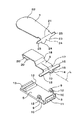
図1乃至図7は、第1実施形態を示す。図1はゴルフ用マーカー保持具を被取付部材に取り付けた状態を示し、図2は、ゴルフ用マーカー保持具を被取付部材に取り付ける直前の状態を示す。図3はゴルフ用マーカー保持具の分解した状態を示す。図4、及び図5は、側面の一部を示す。図6及び図7は作用を示す。 1 to 7 show a first embodiment. FIG. 1 shows a state in which the golf marker holder is attached to the attached member, and FIG. 2 shows a state immediately before the golf marker holder is attached to the attached member. FIG. 3 shows an exploded state of the golf marker holder. 4 and 5 show a part of the side surface. 6 and 7 show the operation.
図1、図2に示すように、ゴルフ用マーカー保持具1は、ゴルフ用マーカーMを保持するマーカー保持部2に、クリップ部3を備えた構成である。該クリップ部3は、被取付部材4をクリップする部材である。該被取付部材4としては、例えば、帽子の鍔、ズボン、シャツの襟が該当する。
As shown in FIGS. 1 and 2, the
例えば、前記マーカー保持部2が磁性体で形成された板体によって構成され、ゴルフ用マーカーMが磁石を備えることによって、マーカー保持部2は、ゴルフ用マーカーMを磁気的に着脱可能に保持できるようにすることができる。
For example, when the
前記クリップ部3は、いわゆる、サスペンダクリップと略同形を成して、ズボンのような被取付部材4をクリップできる構成になっており、基板5と、内押さえ6と、外押さえ7とを備えた構成である。
The
図3に示すように、基板5は、上下面が平面で形成された長尺の平板で構成され、図1に示すように、該基板5の下面に、前記マーカー保持部2が接着又は溶着できるようになっている。該基板5の下面が平面で形成された場合には、該基板5とマーカー保持部2との間に隙間が生じることなく、該マーカー保持部2は基板5に確固として取り付けることができる。
As shown in FIG. 3, the
図3に示すように、該基板5の基端からは支持部8が立設され、又、該基板5の基端側の両側縁には、互いに対面する位置に軸受部9,9が立設されていると共に、該軸受部9から基端方向へ向けて支持受段部10,10が連設されている。前記支持部8には支持孔11が形成され、前記軸受部9には軸孔12が形成されている。又、該基板5の先端側内面には、2つの直方体状のシリコン製の当接部13、13が互いに間隔を開けて設けられている。2つの当接部13、13は、基板5の幅方向へ長尺に形成され、基板5の長手方向へは短尺に形成されている。
As shown in FIG. 3, a
図3に示すように、内押さえ6は、一枚の長尺の板材で形成され、その基端から長手方向外方へ向けて突出する差込部14が設けられ、又、基端側近傍の両側縁からは幅方向外方へ向けて支持部15,15が突設されている。更に、該内押さえ6の基端側から先端側へ向けて基端側段差部17と先端側段差部18とが順次設けられている。これら基端側段差部17と先端側段差部18は、共に、内押さえ6の基端側から先端側へ向けて斜め上方又は直角に折曲するようにして形成される。内押さえ6の基端側には二股状の切割部19、19が設けられている。該切割部19、19は、内押さえ6の基端から先端側段差部18の近傍に渡って該内押さえ6の中心線Lに一致して切り欠かれる形状に形成されている。
As shown in FIG. 3, the
該内押さえ6は、弾発性の部材で形成される。又、図3に示すように、該内押さえ6の先端側内面には、2つの直方体状のシリコン製の当接部20、20が間隔を開けて設けられている。2つの当接部20、20は、基板5の幅方向へ長尺に形成され、基板5の長手方向へは短尺に形成されている。
The
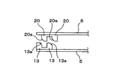
又、図1に示すように、内押さえ6が閉じた状態においては、図4に示すように、基板5に設けられた当接部13と、内押さえ6に設けられた当接部20とは、互い違いになる位置に設けられて、これら当接部13、20によって、被取付部材4を確固として挟持できるようになっている。更に、内押さえ6が基板5に対して接近する際に、基板5に設けられている当接部13の先端部をテーパー状13aに形成することにより、内押さえ6に設けられている当接部20が、基板5側の当接部13に衝突しないようになっている。尚、同図4に示すように、内押さえ6に設けられている当接部20の先端部も同様の理由でテーパー状20aに形成しても良い。図4は、内押さえ6、及び基板5の先端側の側面図である。
Further, as shown in FIG. 1, when the
図3において、前記内押さえ6は、差込部14が前記基板5の先端側から支持孔11に接近させるようにして該支持孔11に差し込まれ、且つ、支持部15、15が基板5の支持受段10,10部に載置されるようにして、該基板5上に設けられると共に、内押さえ6の先端側と基板5との間は、被取付部材が挿入される挿入口P(図2に示す)となり、且つ、該内押さえ6の先端側は挟持端6aとなって、該挟持端6aと基板5との間で被取付部材4を挟持できるようになっている。
In FIG. 3, the
図3に示すように、外押さえ7は、一枚の板材で形成され、且つ、途中に設けられた折曲部21で折曲されるようにして形成されることによって、側面から観た場合、略L字状を成している。該外押さえ7の先端側が操作部22になり、基端側が押圧部23になっている。図3に示すように、該押圧部23は、外押さえ6の基端に2つの山形の凸部24を設けるようにして形成される。これら2つの各凸部24は、前記内押さえ6の2つの各切割部19,19の上面に当接する位置に設けられている。前記折曲部21よりも基端側の位置には外押さえ6の側縁から両側方へ向けて軸部25、25が突設されている。図3に示すように、該外押さえ7は、前記内押さえ6の外側において、その軸部25、25を、基板5の軸受部9に設けられた軸孔12に挿入させるようにして基板5に組み付けられる。
As shown in FIG. 3, the
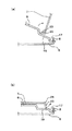
次に、作用について説明する。先ず、図2に示すように、外押さえ7の操作部22を内押さえ6の先端側から離間させるようにして、外押さえ7を軸部25を中心に回転させることによって、図5(a)に示すように、該外押さえ7は、その回転中心、即ち、軸部25よりも先端側に押圧部23を位置させる。この場合、内押さえ6は、外押さえ7の軸部25よりも先端側の位置において、該押圧部23を上方(図5(a)中、矢示方向)へ押し上げるように付勢するため、外押さえ7は、その先端側が内押さえ6の挟持端から離間する方向へ付勢されて同図5(a)に示す状態が維持される。この状態が、図2に示すように、挿入口Pの開状態である。図5は、基板5、内押さえ6、外押さえ7を側面側から観た状態を示す図である。
Next, the operation will be described. First, as shown in FIG. 2, the operating
次に、図2中、二点鎖線で示す被取付部材4に対して、ゴルフ用マーカー保持具1を接近させて、該ゴルフ用マーカー保持具1の挿入口P内へ該被取付部材4を挿入する。
Next, in FIG. 2, the
その後、図1に示すように、ゴルファーが、該ゴルフ用マーカー保持具1の操作部22を内押さえ6の先端側へ倒して該内押さえ6の挟持端6aを基板5側へ押圧して、該内押さえ6の挟持端6aと基板5との間で被取付部材4を挟持するようにして、該ゴルフ用マーカー保持具1を被取付部材4に取り付ける。この状態が、図1に示すように、挿入口Pの閉状態である。
Thereafter, as shown in FIG. 1, the golfer depresses the
この場合、図5(b)に示すように、内押さえ7の切割部19は、軸部25よりも基端側において、外押さえ7の押圧部23を上方(図5(b)中、矢示方向)へ押し上げるように付勢するため、外押さえ7は、その先端側が内押さえ6の挟持端6aに接近する方向へ付勢されて図1示す状態が維持されることによって、該ゴルフ用マーカー保持具1が被取付部材4を挟持するようにして該被取付部材4に取り付けられた状態が維持される。
In this case, as shown in FIG. 5 (b), the
ところで、図6に基づいて、ゴルフ用マーカー保持具1を、薄手の被取付部材4に取り付けた場合と、厚手の被取付部材4に取り付けた場合とについて説明する。薄手の被取付部材4に取り付けた場合、内押さえ6及び外押さえ7は、図6(a)に示す位置にあって、挿入口Pの縦幅はT1である。この場合、外押さえ7の押圧部23は、内押さえ6から矢示方向のバネ力を受けることによって、該外押さえ7の先端側は、内押さえ6の挟持端6aを被取付部材4へ押し付けるように作用することによって、被取付部材4は、基板5と、内押さえ6及び外押さえ7によって挟持され続けて、脱落しない。
By the way, based on FIG. 6, the case where the
次に、ゴルフ用マーカー保持具1を厚手の被取付部材4に取り付けた場合、外押さえ7、及び内押さえ6は図6(b)に示す位置にあって、挿入口Pの縦幅T2は、前述の図6(a)に示す場合よりも拡がっている。この場合、内押さえ6は、図3に示すように、その基端側において、差込部14が基板5の支持孔11に差し込まれ、且つ、内押さえ6の支持部15、15が基板5の支持受段部10に載置されていることによって、同図6(b)に示すように、撓むように湾曲する。
Next, when the
内押さえ6は、弾発性の部材で形成されているため、撓むように変形できる上に、基端側段差部17、及び先端側段差部18が段状から平板に近付くように変形しながら撓むことができる。しかも、この場合においても、前述と同様に、外押さえ7の押圧部23は内押さえ6から図6(b)中、矢示方向のバネ力を受けることによって、該外押さえ7の先端側は、内押さえ6の挟持端6aを被取付部材4へ押し付けるように作用することによって、被取付部材4は、基板5と、内押さえ6及び外押さえ7によって挟持され続けて、脱落しない。
Since the
以上説明したように、外押さえ7の押圧部23が、図5(b)に示すように、該外押さえ7の回転中心である軸部25よりも基端側において内押さえ6の切割部19上面に当接している状態にあっては、該外押さえ7は内押さえ6のバネ力によって挿入口Pを閉塞する方向へ付勢される閉位置にあり、一方、図5(a)に示すように、外押さえ7の押圧部23が、該外押さえ7の回転中心である軸部25よりも先端側において内押さえ6の切割部19上面に当接している状態にあっては、該外押さえ7は内押さえ6のバネ力によって挿入口Pを開放する方向へ付勢される開位置に保持される。
As described above, the
以上説明したように、本実施形態に係るゴルフ用マーカー保持具1は、被取付部材4が薄手であっても厚手であっても、当該被取付部材4に確固として取り付けられることができる。
As described above, the
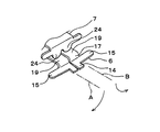
しかも、外押さえ7の押圧部23が内押さえ6の切割部19を撓ませるように変形させることの反作用としてのバネ力、及び該切割部19を図7中、矢印A,Bで示すように、左右に捩るように変形させることの反作用としてのバネ力によって、該外押さえ7が内押さえ6を被取付部材4側へ押圧するものであって、切割部19を有さない内押さえ6が撓むように変形する時の反作用としてのバネ力のみによる場合に比較して、強いバネ力を得ることができる。
Moreover, as shown by arrows A and B in FIG. 7, the spring force as a reaction of the
又、内押さえ6が撓むように変形する場合の反作用のみによって大きなバネ力を得ようとした場合、該内押さえ6は大きく変形しなければならない。しかし、当該実施形態のように、内押さえ6が撓むように変形し、しかも、図7に示すように、切割部19、19が左右に捩るように変形することの反作用とが相俟ってバネ力を得ようとした場合、内押さえ6が撓むことによる変形量、及び内押さえ6の切割部19、19が捩るように変形することによる変形量のそれぞれの変形量は少なくて済むため、内押さえ6は、過度の撓みによる変形、又は切割部19、19が過度に捩るように変形することによって損傷する虞が少なく、経年的使用にも耐えることができる。図7は、図1中、矢示C方向から観た状態であって、外押さえ7の押圧部23と、内押さえ6との力の関係を示す図である。
Further, when a large spring force is to be obtained only by a reaction when the
更に、図4に示すように、基板5に設けられているシリコン製の当接部13と、内押さえ6に設けられているシリコン製の当接部20とが互い違いに設けられていることによって、これら両当接部13,20によって、被取付部材4を挟持するようにして、当該被取付部材4にゴルフ用マーカー保持具2を確固として取り付けることができる。クリップ部3は、新品の場合、シリコン製の当接部13、20の凹凸の食い込みが深いが、厚手の帽子等を挟持して、内押さえ6が曲がる等のダメージを受けた場合、食い込みが浅くなる。しかし、それであっても、シャツ等の薄手の被取付部材4を挟持する際に充分の効果を得ることができる。又、当接部13、20は、シリコン製であって軟らかい素材であるために、該当接部13、20によって被取付部材4を挟持する際に該被取付部材4を傷付ける虞が少ない。
Further, as shown in FIG. 4, the
又、図2、図3に示すように、基板5は平板によって形成されているものであって、該基板5の縁取りをするように、基板5の縁に沿って立上がり部がない。仮に、基板5の縁取りをするように、該基板5の縁に沿って立上がり部が形成されている場合には、該立上がり部によって、被取付部材4に挟み込んだ跡や傷を残す場合がある。しかし、前記実施形態においては、基板5に縁取りのような立上がり部がないため、被取付部材4に挟み込んだ跡や、傷を残す虞がない。
As shown in FIGS. 2 and 3, the
更に、てこの原理により、比較的弱い力で、外押さえ7の操作部22を操作することにより、内押さえ6をしっかりと押さえることができると共に、外押さえ7による押圧挟持を解除する際にも、比較的弱い力で、外押さえ7の操作部22を操作することにより、外押さえ7による強く確固とした押圧を解除することができる。
Furthermore, by operating the operating
図8は、第2実施形態を示す。この第2実施形態の特徴は、外押さえ7の外面に、マーカー保持部2を接着又は溶着によって取り付け、該マーカー保持部2にゴルフ用マーカーMを磁気的に着脱可能に保持できるようにした点にある。この場合、外押さえ7を平板で形成すれば、マーカー保持部2を接着又は溶着によって容易に外押さえ7の外面に取り付けることができる。
FIG. 8 shows a second embodiment. The feature of the second embodiment is that the
1 ゴルフ用マーカー保持具
2 マーカー保持部
3 クリップ部
4 被取付部材
5 基板
6 内押さえ
6a 挟持端
7 外押さえ
13 当接部
17 基端側段差部
18 先端側段差部
19 切割部
20 当接部
22 操作部
23 押圧部
25 軸部
P 挿入口
R 位置決め部
DESCRIPTION OF
Claims (6)
前記クリップ部は、基板と、該基板に回転自在に設けられた外押さえとを備え、該外押さえを基板に対して閉位置に保持して被取付部材をクリップする一方、該外押さえを基板に対して開位置に保持して被取付部材を開放し、
前記マーカー保持部は、前記基板又は外押さえに取り付けられることを特徴とするゴルフ用マーカー保持具。 The golf marker holding portion for holding the golf marker is provided with a suspender clip type clip portion, and the clip portion is used to clip a member to be attached such as a hat or clothes so that the golf member can be attached to the member to be attached. A marker holder,
The clip portion includes a substrate and an outer presser provided rotatably on the substrate, and holds the outer presser in a closed position with respect to the substrate to clip the attached member, while the outer presser is held on the substrate. Hold the open member against the open position,
The marker holder for golf, wherein the marker holder is attached to the substrate or the outer presser.
前記クリップ部は、基板と、内押さえと、外押さえとを備え、
前記内押さえは、その先端側が前記基板に対して接近又は離間する方向のバネ力が付与された状態でその基端が前記基板に支持され、且つ、その先端側が前記基板に対して閉塞又は接近可能な挟持端となって該挟持端と基板との間に被取付部材が挿入されて挟持される挿入口が形成され、
前記外押さえは、基端側が押圧部になると共に先端側が操作部となり、
前記外押さえは、前記内押さえの外側において前記基板に回転自在に設けられ、該回転に伴って、前記押圧部が前記外押さえの回転中心よりも基端側で前記内押さえの上面に当接することにより、前記操作部は前記挿入口を閉塞する方向のバネ力が前記内押さえから付与されて、前記挿入口の閉状態を維持し、一方、前記押圧部が前記外押さえの回転中心よりも先端側で前記内押さえの上面に当接することにより前記操作部は前記挿入口を開放する方向のバネ力が前記内押さえから付与されて、前記挿入口の開状態を維持し、
前記操作部が操作されることで、前記押圧部が前記内押さえに当接する位置を変更させることによって、前記挿入口の閉塞状態と開放状態とを変更させ、
前記マーカー保持部は、前記基板又は外押さえに取り付けられることを特徴とするゴルフ用マーカー保持具。 A golf marker holding tool provided with a clip portion on a golf marker holding portion for holding a golf marker, and detachably attached to a member to be attached by the clip portion,
The clip portion includes a substrate, an inner presser, and an outer presser,
The inner presser is supported by the substrate with a spring force applied in a direction in which the tip side approaches or separates from the substrate, and the tip side closes or approaches the substrate. An insertion port is formed in which a mounting member is inserted and sandwiched between the sandwiching end and the substrate as a possible sandwiching end,
The outer presser has a proximal end side as a pressing portion and a distal end side as an operation portion.
The outer presser is rotatably provided on the substrate outside the inner presser, and with the rotation, the pressing portion comes into contact with the upper surface of the inner presser at the base end side with respect to the rotation center of the outer presser. As a result, the operating portion is provided with a spring force in a direction to close the insertion port from the inner presser to maintain the closed state of the insertion port, while the pressing portion is more than the rotation center of the outer presser. By abutting the upper surface of the inner presser at the distal end side, a spring force in a direction to open the insertion port is applied from the inner presser to maintain the open state of the insertion port.
By changing the position where the pressing portion abuts against the inner press by operating the operation portion, the closed state and the open state of the insertion port are changed,
The marker holder for golf, wherein the marker holder is attached to the substrate or the outer presser.
前記クリップ部は、基板と、内押さえと、外押さえとを備え、
前記内押さえは、基端側段差と先端側段差とを有し、且つ、基端側には該基端側段差を含んだ部分を二股に切り割りする切割部を設けた形状に形成され、
前記外押さえは、基端側が押圧部になると共に先端側が操作部となり、
前記内押さえは、その先端側が前記基板に対して接近又は離間する方向のバネ力が付与された状態でその基端が前記基板に支持され、且つ、その先端側が前記基板に対して閉塞又は接近可能な挟持端となって該挟持端と基板との間に被取付部材が挿入されて挟持される挿入口が形成され、
前記外押さえは、前記内押さえの外側において前記基板に回転自在に設けられ、該回転に伴って、前記押圧部が前記外押さえの回転中心よりも基端側で前記内押さえの上面に当接することにより、前記操作部は前記挿入口を閉塞する方向のバネ力が前記切割部から付与されて、前記挿入口の閉状態を維持し、一方、前記押圧部が前記外押さえの回転中心よりも先端側で前記内押さえの上面に当接することにより前記操作部は前記挿入口を開放する方向のバネ力が前記切割部から付与されて、前記挿入口の開状態を維持し、
前記操作部が操作されることで、前記押圧部が前記内押さえに当接する位置を変更させることによって、前記挿入口の閉塞状態と開放状態とを変更させ、
前記マーカー保持部は、前記基板又は外押さえに取り付けられることを特徴とするゴルフ用マーカー保持具。 A golf marker holder that includes a clip portion in a golf marker holding portion that holds a golf marker, and is detachably attached to a member to be attached by the clip portion,
The clip portion includes a substrate, an inner presser, and an outer presser,
The inner press has a base end side step and a front end side step, and is formed in a shape provided with a split part that splits the portion including the base end side step into two portions on the base end side,
The outer presser has a proximal end side as a pressing portion and a distal end side as an operation portion.
The inner presser is supported by the substrate with a spring force applied in a direction in which the tip side approaches or separates from the substrate, and the tip side closes or approaches the substrate. An insertion port is formed in which a mounting member is inserted and sandwiched between the sandwiching end and the substrate as a possible sandwiching end,
The outer presser is rotatably provided on the substrate outside the inner presser, and with the rotation, the pressing portion comes into contact with the upper surface of the inner presser at the base end side with respect to the rotation center of the outer presser. As a result, the operating portion is provided with a spring force in the direction of closing the insertion port from the split portion to maintain the closed state of the insertion port, while the pressing portion is more than the rotation center of the outer presser. By abutting the upper surface of the inner presser on the distal end side, the operating portion is given a spring force in a direction to open the insertion port from the split portion, and maintains the open state of the insertion port,
By changing the position where the pressing portion abuts against the inner press by operating the operation portion, the closed state and the open state of the insertion port are changed,
The marker holder for golf, wherein the marker holder is attached to the substrate or the outer presser.
Priority Applications (1)
| Application Number | Priority Date | Filing Date | Title |
|---|---|---|---|
| JP2006007263U JP3127044U (en) | 2006-09-07 | 2006-09-07 | Golf marker holder |
Applications Claiming Priority (1)
| Application Number | Priority Date | Filing Date | Title |
|---|---|---|---|
| JP2006007263U JP3127044U (en) | 2006-09-07 | 2006-09-07 | Golf marker holder |
Publications (1)
| Publication Number | Publication Date |
|---|---|
| JP3127044U true JP3127044U (en) | 2006-11-16 |
Family
ID=43476787
Family Applications (1)
| Application Number | Title | Priority Date | Filing Date |
|---|---|---|---|
| JP2006007263U Expired - Lifetime JP3127044U (en) | 2006-09-07 | 2006-09-07 | Golf marker holder |
Country Status (1)
| Country | Link |
|---|---|
| JP (1) | JP3127044U (en) |
Cited By (2)
| Publication number | Priority date | Publication date | Assignee | Title |
|---|---|---|---|---|
| JP3109213B2 (en) | 1992-01-31 | 2000-11-13 | スズキ株式会社 | Governor lever rotation mechanism for general-purpose engine governor |
| US11484067B2 (en) | 2019-09-18 | 2022-11-01 | Krystal Dubose | Garment with low profile magnetic fasteners |
-
2006
- 2006-09-07 JP JP2006007263U patent/JP3127044U/en not_active Expired - Lifetime
Cited By (2)
| Publication number | Priority date | Publication date | Assignee | Title |
|---|---|---|---|---|
| JP3109213B2 (en) | 1992-01-31 | 2000-11-13 | スズキ株式会社 | Governor lever rotation mechanism for general-purpose engine governor |
| US11484067B2 (en) | 2019-09-18 | 2022-11-01 | Krystal Dubose | Garment with low profile magnetic fasteners |
Similar Documents
| Publication | Publication Date | Title |
|---|---|---|
| CN101849113B (en) | clip | |
| JP3127044U (en) | Golf marker holder | |
| WO2011016503A1 (en) | Clip | |
| US20120279019A1 (en) | Deformable paper clip | |
| JP6344635B2 (en) | Clip and information display tag with the clip attached | |
| JP2007168142A (en) | Shaft tube clip decoration, decorative clip and its mounting method | |
| JP3613091B2 (en) | Jig for thin film formation of electronic parts | |
| KR100452395B1 (en) | conneting structure | |
| JP4093466B2 (en) | Synthetic resin clip | |
| JP3971281B2 (en) | clip | |
| JP3128977U (en) | Clip mounting tool | |
| JP5441647B2 (en) | clip | |
| JP3099680U (en) | Hat clip | |
| JP3909563B2 (en) | Tissue box holder and its mounting structure | |
| CN207190959U (en) | Interface arrangment and the automobile using the interface arrangment | |
| JP3130179U (en) | clip | |
| JP3110718U (en) | Paper clip | |
| JP2002019348A (en) | Holder of sheetlike carrier | |
| JPH10270130A (en) | Connector for sheet-like conductive path | |
| JP3125946U (en) | Golf marker holder | |
| WO2018212241A1 (en) | Attachment tool | |
| JP5305844B2 (en) | Piercing catch | |
| JP2003026180A (en) | Holder for box and fixing structure for holder | |
| JP3065863U (en) | Cufflinks and their holders | |
| JP2001059505A (en) | Appliance for attachment and detachment of metallic clip |
Legal Events
| Date | Code | Title | Description |
|---|---|---|---|
| R150 | Certificate of patent or registration of utility model |
Free format text: JAPANESE INTERMEDIATE CODE: R150 |
|
| FPAY | Renewal fee payment (event date is renewal date of database) |
Free format text: PAYMENT UNTIL: 20091025 Year of fee payment: 3 |
|
| S531 | Written request for registration of change of domicile |
Free format text: JAPANESE INTERMEDIATE CODE: R323531 |
|
| FPAY | Renewal fee payment (event date is renewal date of database) |
Free format text: PAYMENT UNTIL: 20091025 Year of fee payment: 3 |
|
| R350 | Written notification of registration of transfer |
Free format text: JAPANESE INTERMEDIATE CODE: R350 |
|
| FPAY | Renewal fee payment (event date is renewal date of database) |
Free format text: PAYMENT UNTIL: 20101025 Year of fee payment: 4 |
|
| FPAY | Renewal fee payment (event date is renewal date of database) |
Free format text: PAYMENT UNTIL: 20111025 Year of fee payment: 5 |
|
| FPAY | Renewal fee payment (event date is renewal date of database) |
Free format text: PAYMENT UNTIL: 20121025 Year of fee payment: 6 |
|
| FPAY | Renewal fee payment (event date is renewal date of database) |
Free format text: PAYMENT UNTIL: 20121025 Year of fee payment: 6 |
|
| FPAY | Renewal fee payment (event date is renewal date of database) |
Free format text: PAYMENT UNTIL: 20131025 Year of fee payment: 7 |
|
| R250 | Receipt of annual fees |
Free format text: JAPANESE INTERMEDIATE CODE: R250 |
|
| R250 | Receipt of annual fees |
Free format text: JAPANESE INTERMEDIATE CODE: R250 |
|
| R250 | Receipt of annual fees |
Free format text: JAPANESE INTERMEDIATE CODE: R250 |
|
| EXPY | Cancellation because of completion of term |