JP3140055U - Band with a frame connection structure - Google Patents
Band with a frame connection structure Download PDFInfo
- Publication number
- JP3140055U JP3140055U JP2007010147U JP2007010147U JP3140055U JP 3140055 U JP3140055 U JP 3140055U JP 2007010147 U JP2007010147 U JP 2007010147U JP 2007010147 U JP2007010147 U JP 2007010147U JP 3140055 U JP3140055 U JP 3140055U
- Authority
- JP
- Japan
- Prior art keywords
- piece
- connecting shaft
- band
- receiving hole
- connection
- Prior art date
- Legal status (The legal status is an assumption and is not a legal conclusion. Google has not performed a legal analysis and makes no representation as to the accuracy of the status listed.)
- Ceased
Links
Images




Classifications
-
- A—HUMAN NECESSITIES
- A44—HABERDASHERY; JEWELLERY
- A44C—PERSONAL ADORNMENTS, e.g. JEWELLERY; COINS
- A44C5/00—Bracelets; Wrist-watch straps; Fastenings for bracelets or wrist-watch straps
- A44C5/02—Link constructions
- A44C5/10—Link constructions not extensible
- A44C5/107—Link constructions not extensible with links made of more than two elements including connecting elements
Landscapes
- Mutual Connection Of Rods And Tubes (AREA)
- Clamps And Clips (AREA)
Abstract
【課題】駒と連結軸との連結が確実で、長期にわたって支障なくバンドの駒連結を維持できるような構造にした駒連結構造のバンドを提供する。
【解決手段】連結軸3にテーパーを有するCリング4を装着し、連結軸3を外駒1に形成した受け孔2に挿入することにより、Cリング4の大径側4bが外駒1の受け孔2における小径部2b側に係止することになるため、連結軸3と外駒1との連結は容易でありながら、連結後は不用意に抜けるようなことはなく、外駒1と連結軸3との連結が確実で、長期にわたって支障なくバンドの駒連結を維持することができる。
【選択図】図1There is provided a band having a piece connection structure in which the connection between a piece and a connection shaft is ensured and the piece connection of the band can be maintained without hindrance over a long period of time.
A tapered C ring 4 is attached to a connecting shaft 3 and the connecting shaft 3 is inserted into a receiving hole 2 formed in the outer piece 1 so that the large diameter side 4b of the C ring 4 is Since it is locked to the small-diameter portion 2b side in the receiving hole 2, the connection shaft 3 and the outer piece 1 are easily connected to each other. The connection with the connecting shaft 3 is reliable, and the band piece connection can be maintained without trouble for a long time.
[Selection] Figure 1
Description
本考案は、時計バンドや装飾品用のバンドに適用され、複数の駒を連結軸にて連結されて構成される駒連結構造のバンドに関する。 The present invention is applied to a watch band and a band for ornaments, and relates to a band having a piece connection structure in which a plurality of pieces are connected by a connecting shaft.
従来の駒連結構造のバンドとしては、複数の外駒と内駒とが互い違いに配置され、対向して配される対となる外駒を連結軸にて結合し、結合された外駒間の結合軸に内駒を装着することにより、隣接する外駒と内駒とがそれぞれ連結軸にて順次連結される構成のものが一般的である。 As a band of the conventional piece connection structure, a plurality of outer pieces and inner pieces are arranged alternately, and a pair of opposed outer pieces are connected by a connecting shaft, and between the connected outer pieces In general, the inner piece is mounted on the connecting shaft so that the adjacent outer piece and inner piece are sequentially connected by the connecting shaft.
そして、連結軸と各駒との連結構造として、従来、各種のものが提案され実施されてきている。例えば、基本的に各駒をネジで連結固定したり、連結軸に圧入したりする構造のものがある。 Various types of connecting structures between the connecting shaft and each piece have been proposed and implemented. For example, there is basically a structure in which each piece is connected and fixed with a screw or press-fitted into a connecting shaft.
その中で、特許文献1,2に記載されているような断面C状のリング体を用い、バンドにおける連結軸と駒にリング体を介在させて、リング体の弾性を利用して連結軸と駒とを連結固定するようにした構造のものがある。
前記従来のバンドにおける断面C状のリング体にて駒を連結するものでは、リング体の弾性を利用した組立て、および分解を行うため、連結軸と駒との装着および脱着が容易であるという利点がある。 In the conventional band in which the pieces are connected by the ring body having a C-shaped cross section, the assembly and disassembly using the elasticity of the ring body are performed, so that the connection shaft and the piece can be easily attached and detached. There is.
しかしながら、脱着が容易であるということは、リング体に対して脱着方向へ外力が加わると不用意に連結軸と駒との連結状態が解除されてしまうことになる。すなわち、バンドにおける駒連結の維持が確実でないといえ、バンド構造としての信頼性に欠けるという課題がある。 However, the easy attachment / detachment means that the connection state between the connection shaft and the piece is inadvertently released when an external force is applied to the ring body in the attachment / detachment direction. That is, there is a problem that the reliability of the band structure is lacking even though it is not certain that the connection of the frames in the band is reliable.
そこで本考案は、駒連結構造のバンドにおける駒と連結軸との連結が確実で、長期にわたって支障なくバンドの駒連結を維持できるような構造にすることを目的とする。 Accordingly, an object of the present invention is to provide a structure in which the connection between the piece and the connection shaft in the band of the piece connection structure is reliable and the band piece connection can be maintained without any trouble for a long time.
前記目的に鑑み、本考案の駒連結構造のバンドは、複数の駒を連結軸により連結して構成される駒連結構造のバンドにおいて、前記駒に前記連結軸の先端部を受ける受け孔を形成し、該受け孔における前記連結軸の先端部が挿入される側を小径部とし、前記連結軸の先端部に凹部を形成し、該凹部に前記受け孔の前記小径部よりも先端部が小径で、かつ該先端部とは反対方向に向かって大径となるテーパーを有する断面略C状の管体を装着し、前記断面略C状の管体を装着した状態で、前記連結軸を前記受け孔の小径部分を通して前記受け孔内へ挿入し、該挿入した状態で前記管体のテーパー部の大径側が前記受け孔の小径部の内側に係止するように構成したことを特徴とする。In view of the above-mentioned object, the band of the piece connection structure of the present invention is a piece connection structure band formed by connecting a plurality of pieces by a connection shaft, and a receiving hole for receiving the tip of the connection shaft is formed in the piece. The side of the receiving hole into which the distal end portion of the connecting shaft is inserted is a small diameter portion, a concave portion is formed at the distal end portion of the connecting shaft, and the distal end portion has a smaller diameter than the small diameter portion of the receiving hole in the concave portion. And a tube having a substantially C-shaped cross section having a taper having a large diameter in a direction opposite to the tip, and the connecting shaft is connected to the tube with the tube having a substantially C-shaped cross section. The tube is inserted into the receiving hole through the small diameter portion of the receiving hole, and in the inserted state, the large diameter side of the tapered portion of the tubular body is locked inside the small diameter portion of the receiving hole. .
また、前記駒において、前記受け孔の部位と前記小径部の部位とを別部材にて形成したことを特徴とする。 Further, in the piece, the receiving hole portion and the small diameter portion portion are formed by separate members.
また、前記駒が外駒であり、該外駒間の前記連結軸に内駒を装着することを特徴とする。 The piece is an outer piece, and the inner piece is mounted on the connecting shaft between the outer pieces.
本考案によれば、連結軸にテーパーを有する断面略C状の管体を装着し、連結軸を駒に形成した受け孔に挿入することにより、管体のテーパー部の大径側が駒の受け孔における小径部内側に係止することになるため、連結軸と駒との連結は容易でありながら、連結後は不用意に抜けるようなことはなく、駒と連結軸との連結が確実で、長期にわたって支障なくバンドの駒連結を維持できる。 According to the present invention, a pipe having a substantially C-shaped cross section with a taper is attached to the connecting shaft, and the connecting shaft is inserted into a receiving hole formed in the piece, so that the large diameter side of the tapered portion of the pipe is the receiving hole of the piece. Because it will be locked to the inside of the small-diameter part in, the connection between the connecting shaft and the piece is easy, but it will not come out carelessly after the connection, the connection between the piece and the connecting shaft is reliable, The band piece connection can be maintained without any trouble for a long time.
また、駒の受け孔における小径部の部位を他の部位とは別部材にて形成することにより、駒の製作が容易になる。 In addition, it is easy to manufacture the piece by forming the small-diameter portion of the receiving hole of the piece with a member different from other parts.
以下に、本考案の好適な実施の形態を図面に基づいて説明する。 Hereinafter, preferred embodiments of the present invention will be described with reference to the drawings.
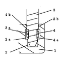
図1は本考案の好適な実施の形態である駒連結構造のバンドの主要部である外駒の連結部分を示す断面図、図2は外駒の連結部分の分解図、図3(a)は連結部材であるCリングの左側面と正面と右側面を示す図、図3(b)は連結部材である連結軸を示す図、図4(a)は外駒の側面図、図4(b)は外駒の平面図である。 FIG. 1 is a sectional view showing a connecting portion of an outer piece which is a main part of a band of a piece connecting structure which is a preferred embodiment of the present invention, FIG. 2 is an exploded view of the connecting portion of the outer piece, and FIG. The figure which shows the left side of the C ring which is a member, the front, and the right side, FIG.3 (b) is a figure which shows the connecting shaft which is a connecting member, FIG.4 (a) is a side view of an outer piece, FIG.4 (b) is FIG. It is a top view of an outer piece.
図1,図2において、1は一対の受け孔2が形成された外駒、3は連結軸、4はテーパーを有する断面略C状の管体のCリングである。 1 and 2,
図1,図4に示すように、外駒1の受け孔2内部に大径部2aが形成され、開口部分が小径部2bとなっている。 As shown in FIGS. 1 and 4, a large-diameter portion 2a is formed inside the
図1,図3(b)に示すように、連結軸3の両先端部にはCリング4が嵌合する小径の凹部3aが形成されている。 As shown in FIGS. 1 and 3B, a small-diameter recess 3 a into which the C-
図2,図3(a)に示すように、Cリング4は、側部に割溝部5が形成され、図2に示すように、そのテーパーが連結部3の先端部側とは反対に向って大径となるように、連結部3の凹部3aに嵌合されて、外駒1の受け孔2に挿入される。 As shown in FIGS. 2 and 3A, the C-
そして、図5(a)に示すように、連結軸3の両先端部が一対の外駒1の受け孔2に挿入され、図5(b)に示すように、Cリング4によって外駒1と連結軸3とが連結される。その連結状態は図1に示すようになる。 As shown in FIG. 5 (a), both ends of the connecting
外駒1と連結軸3との連結について、図1,図2,図5(a),(b)に基づいて具体的に説明する。まず、Cリング4を装着した状態で連結軸3の先端を、外駒1の受け孔2の小径部2bに入れると、Cリング4は小径側4aが受け孔2の小径部2bに向いているためスムーズに入る。連結軸3をさらに奥へ入れると、Cリング4の大径側4bが周方向に縮むように撓み、これによりCリング4全体が受け孔2の小径部2bを通って大径部2a内に入ることになる。 The connection between the
このようにして、Cリング4全体が受け孔2の大径部2a内に入ると、Cリング4の大径側4bは受け孔2内部で径が元の径に戻り、大径側4bの端部が受け孔2の小径部2bにおける内側部分で係止されることになる。 Thus, when the entire C-
したがって、図1に示す状態では、連結軸3における凹部3aの段部とCリング4の小径側4aとが係止状態となり、また、Cリング4の大径側4bと受け孔2の内側一部とが係止状態となるため、連結軸3は外駒1とか容易に外れることなく連結される。 Accordingly, in the state shown in FIG. 1, the stepped portion of the
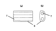
本駒連結構造のバンドは、複数の駒を連結軸により連結して構成される駒連結構造のバンドであって、図6〜図8に示すように、外駒1間に連結軸3にて保持される内駒6を設ける構造になっている。内駒6には、図7(a)の平面図と図7(b)に示す側面図に示すように、一対の貫通孔7が形成されており、貫通孔7に連結軸3を挿入することにより、図8に示すような連結駒構造にする。この連結駒構造を連続して連結することにより、所望長さのバンドを作製する。 The band of this piece connection structure is a band of a piece connection structure configured by connecting a plurality of pieces by a connection shaft, and as shown in FIGS. The
図9(a)〜(g)は図8に示す連結駒構造の組立工程を説明する斜視図であり、まず、連結軸3の両凹部3aに、テーパーを上述した向きにして、それぞれCリング4を装着する(図9(a),(b))。この状態で連結軸3を一方の外駒1の受け孔2に挿入すると(図9(c))、連結軸3と一方の外駒1とが上述したように連結される(図9(d))。 9 (a) to 9 (g) are perspective views for explaining the assembly process of the connecting piece structure shown in FIG. 8. First, in both
この状態で連結軸3に内駒6の貫通孔7を入れ、連結軸3に内駒6を装着する(図9(e),(f))。そして外駒6から外部に出ている連結軸3を、他方の外駒1の受け穴2に挿入する(図9(g))。これによって、上述したと同様に両外駒1が連結軸3に連結され、内駒6が外駒1間で連結軸3に保持される構造となる。 In this state, the
このように本実施の形態では、連結軸3にテーパーを有するCリング4を装着し、連結軸3を外駒1に形成した受け孔2に挿入することにより、Cリング4の大径側4bが外駒1の受け孔2における小径部2b側に係止することになるため、連結軸3と外駒1との連結は容易でありながら、連結後は不用意に抜けるようなことはなく、外駒1と連結軸3との連結が確実で、長期にわたって支障なくバンドの駒連結を維持できる。 As described above, in the present embodiment, the C-
なお、外駒1の受け孔2における小径部2bの部位を、外駒1の他の部位とは別部材にて形成し、小径部2b部分の部材と、他の部分の部材とを一体に接合して駒にすることにより、外駒1の製作が容易になる。 In addition, the part of the small diameter part 2b in the
本考案は、各種バンド類、特に装身具などの身体に着ける各種のバンドに適用され、また多様な意匠展開を図ることも可能である。 The present invention can be applied to various types of bands, particularly various types of bands that can be worn on the body, such as jewelry, and can be used for various design developments.
1 外駒
2 受け孔
2a 大径部
2b 小径部
3 連結軸
3a 凹部
4 Cリング
4a 小径側
4b 大径側
5 割溝部
6 内駒
7 貫通孔DESCRIPTION OF
Claims (3)
前記駒に前記連結軸の先端部を受ける受け孔を形成し、該受け孔における前記連結軸の先端部が挿入される側を小径部とし、
前記連結軸の先端部に凹部を形成し、該凹部に前記受け孔の前記小径部よりも先端部が小径で、かつ該先端部とは反対方向に向かって大径となるテーパーを有する断面略C状の管体を装着し、
前記断面略C状の管体を装着した状態で、前記連結軸を前記受け孔の小径部分を通して前記受け孔内へ挿入し、該挿入した状態で前記管体のテーパー部の大径側が前記受け孔の小径部の内側に係止するように構成したことを特徴とする駒連結構造のバンド。In the band of the piece connection structure constituted by connecting a plurality of pieces by a connecting shaft
A receiving hole for receiving the tip of the connecting shaft is formed in the piece, and a side where the tip of the connecting shaft in the receiving hole is inserted is a small diameter portion,
A concave section is formed at the distal end portion of the connecting shaft, and the concave portion has a taper in which the distal end portion has a smaller diameter than the small diameter portion of the receiving hole and has a larger diameter in a direction opposite to the distal end portion. Wear a C-shaped tube,
With the tubular body having a substantially C-shaped cross section attached, the connecting shaft is inserted into the receiving hole through the small diameter portion of the receiving hole, and in the inserted state, the large diameter side of the tapered portion of the tubular body is the receiving part. A band having a frame connecting structure, wherein the band is configured to be locked inside the small diameter portion of the hole.
Priority Applications (2)
| Application Number | Priority Date | Filing Date | Title |
|---|---|---|---|
| JP2007010147U JP3140055U (en) | 2007-12-12 | 2007-12-12 | Band with a frame connection structure |
| CH19442008A CH698226A2 (en) | 2007-12-12 | 2008-12-11 | BAND WITH chained ELEMENT STRUCTURE. |
Applications Claiming Priority (1)
| Application Number | Priority Date | Filing Date | Title |
|---|---|---|---|
| JP2007010147U JP3140055U (en) | 2007-12-12 | 2007-12-12 | Band with a frame connection structure |
Related Child Applications (1)
| Application Number | Title | Priority Date | Filing Date |
|---|---|---|---|
| JP2008206346A Continuation JP5093814B2 (en) | 2008-07-11 | 2008-07-11 | Band with a frame connection structure |
Publications (1)
| Publication Number | Publication Date |
|---|---|
| JP3140055U true JP3140055U (en) | 2008-03-13 |
Family
ID=40806199
Family Applications (1)
| Application Number | Title | Priority Date | Filing Date |
|---|---|---|---|
| JP2007010147U Ceased JP3140055U (en) | 2007-12-12 | 2007-12-12 | Band with a frame connection structure |
Country Status (2)
| Country | Link |
|---|---|
| JP (1) | JP3140055U (en) |
| CH (1) | CH698226A2 (en) |
Cited By (2)
| Publication number | Priority date | Publication date | Assignee | Title |
|---|---|---|---|---|
| CN114652061A (en) * | 2020-12-22 | 2022-06-24 | 科马杜尔公司 | Assembly of elements such as links of a bracelet |
| JP7660498B2 (en) | 2021-12-28 | 2025-04-11 | シチズン時計株式会社 | Pins for watch parts, watch bands and watches |
Families Citing this family (2)
| Publication number | Priority date | Publication date | Assignee | Title |
|---|---|---|---|---|
| KR100998505B1 (en) * | 2010-04-28 | 2010-12-07 | 주식회사 세라트 | Watchband with semi-permanent assembly structure considering ceramic characteristics |
| EP3130248A1 (en) * | 2015-08-13 | 2017-02-15 | ECCO Watch Co., Ltd. | Ceramic watch chain |
-
2007
- 2007-12-12 JP JP2007010147U patent/JP3140055U/en not_active Ceased
-
2008
- 2008-12-11 CH CH19442008A patent/CH698226A2/en not_active Application Discontinuation
Cited By (4)
| Publication number | Priority date | Publication date | Assignee | Title |
|---|---|---|---|---|
| CN114652061A (en) * | 2020-12-22 | 2022-06-24 | 科马杜尔公司 | Assembly of elements such as links of a bracelet |
| JP2022099247A (en) * | 2020-12-22 | 2022-07-04 | コマディール・エス アー | Assembly of elements such as links of wristlet |
| JP7323587B2 (en) | 2020-12-22 | 2023-08-08 | コマディール・エス アー | Aggregation of elements such as arm band pieces |
| JP7660498B2 (en) | 2021-12-28 | 2025-04-11 | シチズン時計株式会社 | Pins for watch parts, watch bands and watches |
Also Published As
| Publication number | Publication date |
|---|---|
| CH698226A2 (en) | 2009-06-15 |
Similar Documents
| Publication | Publication Date | Title |
|---|---|---|
| WO2008126727A1 (en) | Structure for connection between flexible tube for endoscope and annular connection member | |
| CN104161356B (en) | Assemble the system of at least three parts | |
| US8371768B1 (en) | Connectin unit for tubes | |
| JP3137121U (en) | Band with a frame connection structure | |
| CN201518804U (en) | Lock fastener for connecting two ends of textile tape | |
| TWI706833B (en) | Bending torque wrench | |
| JP5093814B2 (en) | Band with a frame connection structure | |
| JP3149703U (en) | Band piece for adjustment piece, watch band and watch | |
| JP2015217273A (en) | Band of piece connection structure | |
| JP3148398U (en) | Urethane piece for watchband and watchband with the same | |
| KR200445644Y1 (en) | glasses | |
| JP2014069059A (en) | Band of piece connecting structure | |
| JP3160600U (en) | Band with a frame connection structure | |
| JP5845642B2 (en) | band | |
| ATE431907T1 (en) | SLEEVE AND COMPONENT PROVIDED WITH IT | |
| JP3149806U (en) | band | |
| JP3949082B2 (en) | Guard body and core material fastening device for utility pole guard | |
| KR101843071B1 (en) | Insert type hinge | |
| JP3118257U (en) | Suspended blind | |
| JP2011218137A (en) | Band of piece connecting structure | |
| JP3156269U (en) | Sliding parts for jewelry | |
| KR200315654Y1 (en) | structure of combination for fishing rod | |
| JP2006288814A (en) | Connecting structure of case body and band | |
| JP3062207U (en) | Structure to prevent pulling out of outer pin in piece connecting band | |
| TWI471201B (en) | Pneumatic tool rotor and hammer block shell seat fixed structure |
Legal Events
| Date | Code | Title | Description |
|---|---|---|---|
| R150 | Certificate of patent or registration of utility model |
Free format text: JAPANESE INTERMEDIATE CODE: R150 |
|
| FPAY | Renewal fee payment (event date is renewal date of database) |
Free format text: PAYMENT UNTIL: 20110220 Year of fee payment: 3 |
|
| FPAY | Renewal fee payment (event date is renewal date of database) |
Free format text: PAYMENT UNTIL: 20110220 Year of fee payment: 3 |
|
| S531 | Written request for registration of change of domicile |
Free format text: JAPANESE INTERMEDIATE CODE: R323531 |
|
| FPAY | Renewal fee payment (event date is renewal date of database) |
Free format text: PAYMENT UNTIL: 20110220 Year of fee payment: 3 |
|
| R350 | Written notification of registration of transfer |
Free format text: JAPANESE INTERMEDIATE CODE: R350 |
|
| FPAY | Renewal fee payment (event date is renewal date of database) |
Free format text: PAYMENT UNTIL: 20110220 Year of fee payment: 3 |
|
| S801 | Written request for registration of abandonment of right |
Free format text: JAPANESE INTERMEDIATE CODE: R321801 |
|
| ABAN | Cancellation due to abandonment | ||
| FPAY | Renewal fee payment (event date is renewal date of database) |
Free format text: PAYMENT UNTIL: 20110220 Year of fee payment: 3 |
|
| R350 | Written notification of registration of transfer |
Free format text: JAPANESE INTERMEDIATE CODE: R350 |