JP3140475U - Slide falling prevention device for press machine - Google Patents
Slide falling prevention device for press machine Download PDFInfo
- Publication number
- JP3140475U JP3140475U JP2008000130U JP2008000130U JP3140475U JP 3140475 U JP3140475 U JP 3140475U JP 2008000130 U JP2008000130 U JP 2008000130U JP 2008000130 U JP2008000130 U JP 2008000130U JP 3140475 U JP3140475 U JP 3140475U
- Authority
- JP
- Japan
- Prior art keywords
- shaft
- state
- metal fitting
- lowered
- main body
- Prior art date
- Legal status (The legal status is an assumption and is not a legal conclusion. Google has not performed a legal analysis and makes no representation as to the accuracy of the status listed.)
- Expired - Lifetime
Links
Images

Landscapes
- Control Of Presses (AREA)
Abstract
【課題】1ポートへの流体供給によって、回転阻止金具の下降位置でのロック解除、回転阻止金具の上昇、上昇位置でのロックを行い、別のポートへの流体供給によって、回転阻止金具の上昇位置でのロック解除、回転阻止金具の下降、下降位置でのロックを行う。
【解決手段】本体2内の下端部に進退可能に設けた回転阻止金具4が、下端部よりも下降した下降状態においてプレス機械のスライドを駆動する歯車の歯間に侵入する。金具4を下降状態と、歯間から脱出した上昇状態とに、昇降機構が駆動する。昇降機構では、本体内にシャフト14、20、28が設けられ、金具4を設けた金具取付部8がこのシャフトの下端に、シャフトの上昇に応じてシャフトに連動し、シャフトの下降に応じてシャフトと非連動となるように設けられている。
【選択図】図1An object of the present invention is to release a lock at a lowered position of a rotation prevention metal fitting by raising a fluid to one port, raise a rotation prevention metal fitting, lock at an elevated position, and raise the rotation prevention metal fitting by supplying a fluid to another port. Release the lock at the position, lower the rotation prevention metal fitting, and lock at the lowered position.
A rotation preventing metal fitting 4 provided at a lower end portion in a main body 2 so as to be able to advance and retreat enters between teeth of a gear driving a slide of a press machine in a lowered state lower than the lower end portion. The raising / lowering mechanism is driven in the lowered state of the metal fitting 4 and the raised state of escape from between the teeth. In the lifting mechanism, the shafts 14, 20, and 28 are provided in the main body, and the bracket mounting portion 8 provided with the bracket 4 is linked to the shaft at the lower end of the shaft according to the rise of the shaft, and according to the lowering of the shaft. It is provided so as not to be interlocked with the shaft.
[Selection] Figure 1
Description
本考案は、プレス機械のスライド落下防止装置に関し、特にプレス機械のスライドを駆動する歯車の回転を阻止することによってスライドの落下を防止するものに関する。 The present invention relates to a slide fall prevention device for a press machine, and more particularly to an apparatus for preventing the slide from falling by preventing the rotation of a gear that drives the slide of the press machine.
従来、上記のようなスライド落下防止装置としては、例えば特許文献1に開示されているようなものがある。特許文献1の技術によれば、スライドモジュールが歯車の歯の間に挿入される。 Conventionally, as such a slide fall prevention device, for example, there is a device disclosed in Patent Document 1. According to the technique of Patent Document 1, a slide module is inserted between gear teeth.
この他に、シリンダ本体内にシャフトを設け、このシャフトの下端に歯車の歯の間に挿入される回転阻止金具を設け、このシャフトを下降位置(回転阻止金具が歯車の歯間に挿入されている位置)と上昇位置(回転阻止金具が歯車の歯間から上方に脱出した位置)との間で昇降するように上昇下降用に油圧切換バルブを設け、下降位置及び上昇位置にシャフトをロックしたりアンロックしたりするためのボールロック機構をそれぞれ設け、このボールロック機構をロック状態としたり、アンロック状態としたりするための油圧切換バルブを設けたものもあった。 In addition to this, a shaft is provided in the cylinder body, a rotation prevention metal fitting inserted between the gear teeth is provided at the lower end of the shaft, and the shaft is moved down (the rotation prevention metal fitting is inserted between the gear teeth). Provided with a hydraulic switching valve for ascending and descending so that it moves up and down between the raised position and the raised position (position where the anti-rotation bracket escapes upward from between the gear teeth), and locks the shaft in the lowered and raised positions. Some ball lock mechanisms are provided for unlocking and unlocking, and a hydraulic switching valve is provided for setting the ball lock mechanism in a locked state or in an unlocked state.
しかし、上述したような構成では、下降位置でボールロックされている状態においてボールロック・アンロック切換用のバルブが誤動作すると、ボールロックが解除された状態になり、危険である。 However, in the configuration as described above, if the ball lock / unlock switching valve malfunctions while the ball is locked at the lowered position, the ball lock is released, which is dangerous.
本考案は、1つのポートに流体を供給することによって、回転阻止金具の下降位置でのロック状態の解除、回転阻止金具の上昇、上昇位置でのロックを行うことができ、かつ別のポートに流体を供給することによって、回転阻止金具の上昇位置でのロック状態の解除、回転阻止金具の下降、下降位置でのロックを行えるプレス機械のスライド落下防止装置を提供することを目的とする。 By supplying a fluid to one port, the present invention can release the locked state at the lowered position of the rotation prevention metal fitting, raise the rotation prevention metal fitting, and lock at the raised position. An object of the present invention is to provide a slide fall prevention device for a press machine that can release a locked state at a raised position of a rotation prevention metal fitting, lower a rotation prevention metal fitting, and lock at a lowered position by supplying a fluid.
本考案の一態様によるプレス機械のスライド落下防止装置は、シリンダ状の本体を有している。この本体内の下端部に前記本体の長さ方向に沿って進退可能に回転阻止金具が設けられ、この回転阻止金具は前記下端部よりも下降した下降状態において、プレス機械のスライドを駆動する歯車の歯間に侵入する。この回転阻止金具を前記下降状態と、前記先端金具が前記歯間から脱出した上昇状態とに、駆動する昇降機構が設けられている。昇降機構では、前記本体の長さ方向に沿って摺動可能に前記本体内にシャフトが設けられている。このシャフトの下端に、前記回転阻止金具を設けた金具取付部が、前記シャフトの上昇に応じて前記金具取付部が前記シャフトに連動し、前記シャフトの下降に応じて前記金具取付部が前記シャフトと非連動となるように、設けられている。前記シャフトが前記下降状態にあるとき、前記金具取付部の上昇を阻止する下側ロック機構が設けられている。前記シャフトにおける前記金具取付部よりも上側に上昇用ピストンが設けられている。前記本体内には前記上昇用ピストンに上昇用の流体圧を供給する上昇用流体室が設けられている。上記シャフトの上昇時に圧縮されるバネ部材が前記本体内に設けられている。前記シャフトが前記上昇状態にあるとき、前記シャフトの下降を阻止する上側ロック機構が設けられている。前記本体内に前記上側ロックのロックを解除する解除用ピストンが設けられている。前記シリンダ内には前記解除用ピストンに上昇用の流体圧を供給する解除用流体室が設けられている。前記上昇用流体室に前記流体を供給すると共に前記解除用流体室から流体を排出する状態と、前記解除用流体室に流体を供給すると共に前記上昇用流体室から流体を排出する状態とに切り換える切換弁が設けられている。 A slide fall prevention device for a press machine according to an aspect of the present invention has a cylindrical main body. A rotation-preventing metal fitting is provided at the lower end of the main body so as to be movable back and forth along the length of the main body. The rotation-preventing metal fitting is a gear that drives the slide of the press machine in a lowered state lower than the lower end. Invades between teeth. An elevating mechanism for driving the rotation preventing metal fitting in the lowered state and an elevated state in which the tip metal fitting escapes from between the teeth is provided. In the lifting mechanism, a shaft is provided in the main body so as to be slidable along the length direction of the main body. The bracket mounting portion provided with the rotation preventing bracket at the lower end of the shaft is interlocked with the shaft according to the rise of the shaft, and the bracket mounting portion according to the lowering of the shaft. It is provided so that it is not interlocked with. When the shaft is in the lowered state, a lower lock mechanism is provided that prevents the bracket mounting portion from being lifted. A lifting piston is provided above the bracket mounting portion of the shaft. A lifting fluid chamber is provided in the main body for supplying a lifting fluid pressure to the lifting piston. A spring member that is compressed when the shaft is raised is provided in the main body. An upper locking mechanism is provided for preventing the shaft from descending when the shaft is in the raised state. A release piston for releasing the lock of the upper lock is provided in the main body. A release fluid chamber is provided in the cylinder for supplying a lifting fluid pressure to the release piston. Switching between the state in which the fluid is supplied to the lifting fluid chamber and the fluid is discharged from the releasing fluid chamber and the state in which the fluid is supplied to the releasing fluid chamber and the fluid is discharged from the lifting fluid chamber A switching valve is provided.
このように構成すると、例えばシャフトが下降状態にあるとすると、回転阻止金具が本体の下部から突出し、シャフトに金具取付部は非連動状態にあり、金具取付部は下側ロック機構によってロックされている。この状態で、上昇用ピストンに流体圧を加えるように切換弁を切り換えると、シャフトが上昇し、下側ロック機構によるロックが解除される。やがて、シャフトの上昇に金具取付部が連動して上昇し、回転阻止金具も上昇する。そして、バネ部材を圧縮しながらシャフトは上昇を続ける。そして、シャフトの先端が上側ロック機構によってロックされる。これによってシャフトが下降することが阻止され、回転阻止金具が上昇状態になる。このように下降位置でのロック状態の解除、回転阻止金具の上昇、上昇位置でのロックは、上昇用ピストンへの流体の供給のみによって行われている。 With this configuration, for example, if the shaft is in the lowered state, the rotation prevention metal fitting protrudes from the lower part of the main body, the metal fitting attachment portion is not interlocked with the shaft, and the metal fitting attachment portion is locked by the lower lock mechanism. Yes. In this state, when the switching valve is switched so as to apply fluid pressure to the lifting piston, the shaft rises and the lock by the lower lock mechanism is released. Eventually, the bracket mounting portion rises in conjunction with the rise of the shaft, and the rotation prevention bracket also rises. The shaft continues to rise while compressing the spring member. Then, the tip of the shaft is locked by the upper lock mechanism. As a result, the shaft is prevented from being lowered, and the rotation prevention metal fitting is raised. Thus, the release of the locked state at the lowered position, the raising of the rotation preventing metal fitting, and the locking at the raised position are performed only by supplying the fluid to the raising piston.
この上昇状態において、解除用ピストンに流体圧を加え、上昇用ピストンへの流体圧を消失させるように切換弁を切り換えると、上側ロック機構によるシャフトのロックが解除される。これによって、圧縮されていたバネ部材が元に復帰しようとする。これに伴ってシャフトが下降する。このときシャフトと金具取付部とは非連動であるが、上昇用ピストンが金具取付部を下方に押すので、金具が下降して、下降位置に到達する。その後、シャフトが降下して、下側ロック機構によって金具取付部がロックされる。このように上昇位置でのロック状態の解除、回転阻止金具の下降、下降位置でのロックは、解除用ピストンへの流体の供給のみによって行われている。 In this raised state, when the fluid pressure is applied to the release piston and the switching valve is switched so that the fluid pressure to the lift piston disappears, the shaft is unlocked by the upper lock mechanism. As a result, the compressed spring member attempts to return to its original state. Along with this, the shaft descends. At this time, the shaft and the bracket mounting portion are not interlocked, but the lifting piston pushes the bracket mounting portion downward, so that the bracket descends and reaches the lowered position. Thereafter, the shaft descends, and the bracket mounting portion is locked by the lower lock mechanism. As described above, the lock state is released at the raised position, the rotation prevention metal fitting is lowered, and the lock at the lowered position is performed only by supplying the fluid to the release piston.
前記上側ロック機構が前記シャフトをロックしているとき通電する第1のスイッチと、前記下側ロック機構が前記シャフトをロックしているとき通電する第2のスイッチと、前記シャフトが前記昇降しているとき非通電状態となり前記シャフトが上昇状態及び下降状態にあるとき通電状態となる第3のスイッチとを設けることもできる。 A first switch that energizes when the upper locking mechanism locks the shaft; a second switch that energizes when the lower locking mechanism locks the shaft; and the shaft moves up and down. It is also possible to provide a third switch which is in a non-energized state when the shaft is in the energized state when the shaft is in the raised and lowered states.
このように構成すると、第1及び第3のスイッチいずれかが通電されているとき上昇状態にあることを確認でき、第2及び第3のスイッチいずれかが通電されているとき下降状態にあることを確認できる。特に、第3のスイッチは、シャフトの上昇位置と下降位置との間での移動に従って通電状態から非通電状態を経て再び通電状態に戻るので、接点の溶着が生じにくい。 With this configuration, it can be confirmed that either the first or third switch is in the raised state when energized, and the second or third switch is in the lowered state when energized. Can be confirmed. In particular, since the third switch returns from the energized state to the non-energized state according to the movement between the ascending position and the descending position of the shaft, the contact is less likely to be welded.
また、シャフトの上端にネジ溝を形成し、本体の上部から前記ネジ溝に螺合するボルト部材を挿入可能に本体を形成することもできる。このように構成すると、なんらかの原因で下降位置で、このプレス機械のスライド落下防止装置が動作不能となって、下降位置でロックされた状態を解除できない状態になっても、ボルト部材をシャフトのネジ溝に螺合させ、ボルト部材によってシャフトを引き上げることにより、下降位置でのロック状態を解除することができる。 Moreover, a thread groove can be formed in the upper end of a shaft, and a main body can also be formed so that the bolt member screwed in the said thread groove from the upper part of a main body can be inserted. With this configuration, even if the slide fall prevention device of the press machine becomes inoperable at the lowered position for some reason and the locked state cannot be released at the lowered position, the bolt member is screwed on the shaft. The locked state at the lowered position can be released by screwing into the groove and pulling up the shaft by the bolt member.
以上のように、本考案によれば、切換弁によって上昇用ピストンに流体圧を加えるか、解除用ピストンに流体圧を加えるかを、切換弁で切り換えるだけで、シャフトの上昇・下降動作と、ロック機構によるロック・アンロックの解除を行うことができ、シャフトの昇降用とロック・アンロックの切換とに別々の切換弁を使用していた場合に生じていた、切換弁の誤動作によるロックの不要な解除が生じることがなく、安全性を高めることができる。 As described above, according to the present invention, the shaft is lifted / lowered only by switching with the switching valve, whether the fluid pressure is applied to the lifting piston or the release piston with the switching valve. The lock mechanism can be used to release the lock / unlock, and the lock caused by the malfunction of the change-over valve, which occurred when separate switch valves were used for lifting the shaft and switching the lock / unlock. Unnecessary release does not occur, and safety can be improved.
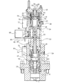
本考案の1実施形態のプレス機械のスライド落下防止装置は、図1及び図2に示すように、シリンダ本体2を有している。
As shown in FIGS. 1 and 2, the slide fall prevention device for a press machine according to an embodiment of the present invention has a
このシリンダ本体2内の下部には、プレス機械のスライドを駆動する歯車の歯間に挿入される回転阻止金具4が配置されている。この金具4は、本体2の長さ方向に沿って摺動可能であり、図1に示すように本体2の下端部から突出した下降状態から、図2に示すように本体2内に後退した上昇状態とを取ることが可能である。
In the lower part of the
この金具4は、ボルト6によって金具取付ロッド8に結合されている。金具取付ロッド8は、本体2内に配置され、その内部が空洞で上部が開口している。本体2内における金具取り付けロッド8の外周には、これと接するようにカラー10が配置され、その上部にはブッシュ12が配置されている。ブッシュ12は、その上部で金具取付ロッド8に接しているが、下部では金具取付ロッド8の外周とは非接触となるように厚さが薄く形成されている。金具取付ロッド8の内部には、下部ロックシャフト14が挿入されている。この下部ロックシャフト14は、シリンダ本体2内をその長さ方向に沿って摺動可能に構成されている。この下部ロックシャフト14の頭部14aは、下降状態においてブッシュ12の厚さが薄くなり始めている部分に位置している。その頭部14aの外周に対応する金具取付ロッド8内には環状に複数のボール16が配置されている。これらがロックシャフト14の頭部14aによってブッシュ12の薄手の部分に押し出され、金具4、金具取付ロッド8がそれ以上に上昇することを阻止されている。即ち、下側のボールロック機構が構成されている。但し、下部ロックシャフト14は、上昇可能である。
The
金具取付ロッド8の上部開口を塞ぐように蓋18が配置されている。蓋18の周囲にはフランジ18aが形成され、これがシリンダ本体2内に形成された段部2aに、下降状態において接触し、これによって金具4等の下降が阻止されている。
A
この蓋18を貫通して上方に下部ロックシャフト14が突出している。その突出部分にボルト20が結合され、このボルト20の回りに上昇用ピストン22が形成されている。このピストン22は、下降状態において蓋18に接触しており、ピストン22の下面の周囲と蓋18の周囲とシリンダ本体2の内周面との間に、流体室、例えば圧油室24が形成されている。この圧油室24がシリンダ本体2に形成したポート26に接続されている。このポート26に圧油が供給されることによって、下部ロックシャフト14は上昇するが、但し、それの頭部14aが蓋18の下部に接触するまでは、下部ロックシャフト14のみが上昇し、金具取付ロッド8等は上昇しない。
A
ピストン22と一体に上部ロックシャフト28が形成されて、シリンダ本体2の上方に向かって伸びている。この上部ロックシャフト28にボルト20が結合されている。これによって下部ロックシャフト14、ボルト20、ピストン22及び上部ロックシャフト28が一体とされて、ロックシャフトを構成している。
An
ピストン22の上面と、これよりも上方のシリンダ本体内の部分に設けたバネ受け部30との間に、上部ロックシャフト28の周囲を包囲するようにバネ、例えばコイルバネ32が、下降状態において非圧縮となるように配置されている。
Between the upper surface of the
上部ロックシャフト28は、バネ受け部30よりも上方にその上端部が位置している。その上端部は径が拡大されている。
The
上部ロックシャフト28の上端部の周囲を包囲するように解除用ピストン34が昇降可能にシリンダ本体2の内周面に接して配置されている。このピストン34の外周面側には流体室、例えば油圧室36が形成されており、これはポート38に接続されている。このポート38に圧油を供給することによってピストン34が上方に上昇している。ピストン34の上部には、ロック金具40が配置されている。このロック金具40は、その下部周縁が、他の部分よりも薄手に形成され、その上部にはコイルバネ42が配置されている。このコイルバネ42は、下降状態において圧縮されて配置されている。シリンダ本体2の上端部を閉じている蓋43の下面からロック部材の内周面に接するようにスリーブ44が下方に伸びており、その下部近傍に複数のボール46が環状に配置されている。ピストン34が上昇している状態において、ボール46は、ロック金具40の下部の薄手の部分に位置している。
A
このスリーブ44の内側に上部が開口した筒状のアンロック金具48が、上方には摺動可能であるが、下方には摺動不能に配置され、その内部には圧縮されていない状態でコイルバネ50が配置されている。コイルバネ50の一端がアンロック金具48の下端に配置され、他端は蓋43に設けたバネ受けプラグ52に配置されている。上部ロックシャフト28が上昇して、その上端がアンロック金具48を押し上げると共に、ピストン34が下降して、ロック金具40が降下すると、ボール46が、上部ロックシャフト28の上端の拡大部よりも幾分下の位置で内側に突出させられ、上部ロックシャフト28が降下するのを阻止される。即ち、ロック金具40、アンロック金具48、ボール46、コイルバネ50によって上側ボールロック機構が構成されている。
A cylindrical unlocking bracket 48 whose upper part is opened inside the
このバネ受けプラグ52には開口54が形成され、この開口54と対応するようにアンロック金具48の下端にも開口56が形成されている。これら開口54、56を介して図示していない長いボルト部材がシリンダ本体2内に挿入可能である。また、上部ロックシャフト28の上端には、このボルト部材が螺合するネジ溝58が形成されている。このネジ溝58にボルト部材を螺合させて、ロックシャフトを上昇させることができる。
An
上昇用ピストン22にはカムドッグ取付板60が設けられ、これの下面に設けた操作子62が、その下方に設けた下降状態検出用のリミットスイッチ64を操作する。このリミットスイッチ64はノーマルオープン型のもので、下降状態において、リミットスイッチ64を操作してオン状態(通電状態)とする。
The ascending
また、この取付板60の上面に設けたカムドッグ66が上昇・下降検出用リミットスイッチ68を操作する。このリミットスイッチ68は、ノーマルクローズのもので、下降状態ではカムドッグ66によって操作されず、オン状態である。また、下降状態から上昇状態に上昇用ピストン22が上昇すると、カムドッグ66も上昇し、上昇・下降検出用リミットスイッチ68を操作してオフ状態として、上昇状態になると、再びカムドッグ66がリミットスイッチ68を操作しない状態になり、リミットスイッチ68はオン状態になる。
A
また、ロック金具40には操作子としてのボルト70が取り付けられ、ロック金具40が降下したとき、即ち、上昇状態になったとき、このボルト70によって操作されるように上昇用検出用リミットスイッチ72が設けられている。このリミットスイッチ72もノーマルオープンのもので、ボルト70が接触したときに、オン状態になる。
Further, a
図1に示すように、ポート26、38には、2つの電磁切換弁74、76によって圧油の給排が行われる。これら電磁切換弁74、76はポート74A、76A、ポート74B、76B、ポート74P、76P、ポート74T、76Tを有している。ポート74A、76Aは、互いに並列に接続されポート26に接続され、ポート74B、76Bは、互いに並列に接続され、ポート38に接続されている。ポート74P、76Pは互いに並列に接続され油圧ポンプ78に接続されている。また、ポート74T、76Tは互いに並列に接続され、タンク80に接続されている。これら切換弁74、76は連動して動作し、下降状態では、ポート74A、76Aがポート74T、76Tと連通し、ポート74B、76Bがポート74P、76Pと連通している。上昇状態では、ポート74A、76Aがポート74P、76Pに連通し、ポート74B、76Bがポート74T、76Tと連通している。
As shown in FIG. 1, pressure oil is supplied to and discharged from the
図1に示す下降状態では、ポート38に圧油が供給され、ポート26から圧油が排出されている。そのため、金具4がシリンダ本体2の下端部から突出し、金具取付ロッド8は上昇が阻止され、蓋18のフランジ18aが段部2aに係合して、金具4及び金具取付部8の下降を阻止している。下部ロックシャフト14の頭部14aは、蓋18よりも下方に位置している。また、解除用ピストン34が上昇して、ロック金具40を上昇させ、バネ42は圧縮状態にあり、上部ロックシャフト28の上端部は、アンロック金具48よりも下方に位置している。この状態では、リミットスイッチ64、68がオン状態で、リミットスイッチ72がオフ状態である。
In the lowered state shown in FIG. 1, the pressure oil is supplied to the
この下降状態において、電磁弁74、76をポート74A、76Aがポート74P、76Pに連通し、ポート74B、76Bがポート74T、76Tと連通する状態に切り換える。これによって、上昇用ピストン22が上昇を開始し、これに伴い下部ロックシャフト14、ボルト20及び上部ロックシャフト28が上昇する。これによって、下部ロックシャフト14の頭部14aがボール16から離れ、金具4及び金具取付ロッド8が上昇可能となる。下部ロックシャフト14が上昇し、頭部14aが蓋18に接触すると、金具4及び金具取付ロッド8が上昇を開始する。一方、コイルバネ32は、上昇用ピストン22の上昇に伴い圧縮されていく。
In this lowered state, the
一方、圧油室36から圧油が排出されるので、解除用ピストン34が降下し、圧縮されていたコイルバネ50が非圧縮の状態に復帰しつつ、ロック金具40を降下させる。一方、上部ロックシャフト28の上端が上昇してきて、コイルバネ50を圧縮しながらアンロック金具48を上方に押す。上部ロックシャフト28の上端の拡大部よりも幾分下側の部分がボール46の位置に到達したとき、即ち、金具4が完全にシリンダ本体2内に収容されたとき、ロック金具40がボール46を上部ロックシャフト28側に押しだし、上部ロックシャフト28をロックする。
On the other hand, since the pressure oil is discharged from the
なお、下降状態から上昇状態に向かって上昇用ピストン22が上昇したことにより、リミットスイッチ64がオフ状態になり、リミットスイッチ68は、オフ状態になる。上昇状態になると、リミットスイッチ68は再びオン状態になる。一方リミットスイッチ72は、ロック金具40が降下したことにより、オン状態になる。
In addition, when the raising
この上昇状態において、電磁切換弁74、76を、ポート74A、76Aがポート74T、76Tと連通し、ポート74B、76Bがポート74P、76Pと連通するように切り換えると、圧油室36に圧油が供給され、解除用ピストン34が上昇を開始し、ロック金具40を上昇させる。これによって、ボール46が外方に移動可能となり、ロック状態が解除される。これによって圧縮されていたコイルバネ50、32が元の状態に復帰し始め、上部ロックシャフト28の上部がアンロック金具48によって下方に押されると共に、上昇用ピストン22がコイルバネ32によって下方に押され、上部ロックシャフト28、ボルト20、下部ロックシャフト14、金具取付ロッド8、蓋18、金具4が降下し始める。やがて、金具4がシリンダ本体2の下端部から突出し、蓋18のフランジ18aが段部2aに接触し、金具4、金具取付ロッド8、蓋18がそれ以上の降下を阻止される。このとき、ボール16がブッシュ12の薄手の部分に到達している。そして、上部ロックシャフト28、ボルト20、下降ロックシャフト14が下降していき、下降ロックシャフト14の頭部14aによってボール16が外方へ押し出され、上昇が不能となる。このとき、ピストン21が蓋18に接触し、それ以上の降下が阻止される。
In this raised state, when the
なお、下降状態では、ロック金具40が上昇したことにより、リミットスイッチ72はオフ状態となり、リミットスイッチ68はオン状態からオフ状態を経て再びオン状態になる。また、リミットスイッチ64はオフ状態からオン状態になる。
In the lowered state, as the lock fitting 40 is raised, the
このようにして、金具4の下降、上昇が行われ、プレス機械のスライドの落下を防止する状態と、それを解除した状態とにすることができる。しかも、下降状態から、下方でのロックを解除して、ロックシャフトを上昇させ、上方でロックして上昇状態とすることと、上昇状態から、上方でのロックを解除して、ロックシャフトを下降させ、下降でロックして下降状態とすることとを、並列接続した電磁切換弁74、76によるポート26、38への圧油の給排のみによって行え、ロック用と昇降用とに別個の電磁弁を設ける必要がない。また、電磁切換弁74、76を並列に接続しているので、例えば下降状態において、一方の電磁弁76が誤動作してポート76Aがポート76Pに、ポート76Bがポート76Tに接続されたとしても、ポート76Aに出力された圧油はポート74Aからタンク80に戻されるので、誤動作することはない。詳細な説明は省略するが、下降状態で、電磁弁74が誤動作した場合も、上昇状態で、電磁弁74、76の一方が誤動作した場合でも、同様である。
In this way, the
また、なんらかの原因で下降状態から上昇状態へ移行させることができなくなった場合、開口54、56を介して長いボルト部材をネジ溝58に螺合させて、ロックシャフトを上昇させ、下降状態から上昇状態に手動で移行させて、スライド落下の防止状態を解除することができる。
In addition, when it becomes impossible to shift from the lowered state to the raised state for some reason, a long bolt member is screwed into the
また、下降状態では、リミットスイッチ68、64が共にオン状態であり、上昇状態では、リミットスイッチ68、72が共にオン状態である。従って、リミットスイッチ68、64を並列に接続し、リミットスイッチ68、72を並列に接続することによって、リミットスイッチ64、68の一方、またはリミットスイッチ68、72の一方が故障しても、下降状態及び上昇状態を確実に検出することができる。また、リミットスイッチ68はノーマルクローズのものを使用しているので、上昇状態から下降状態または下降状態から上昇状態に移行する際、必ずオン状態からオフ状態を経てオン状態となるので、接点が必ず操作され、接点の溶着が起こりにくくなる。
In the lowered state, both
上記の実施形態では、圧油を使用したが、これに限ったものではなく、例えば空気圧や水圧を使用することもできる。また、上記の実施形態では、上昇状態において、金具4を本体2内に完全に収容したが、歯車の歯間から脱出していれば、本体2内に収容する必要はない。
In the above embodiment, pressure oil is used. However, the present invention is not limited to this. For example, air pressure or water pressure can also be used. Moreover, in said embodiment, although the
2 シリンダ本体
4 回転阻止金具
8 金具取付ロッド
14 下部ロックシャフト(ロックシャフト)
20 ボルト(ロックシャフト)
28 上部ロックシャフト(ロックシャフト)
16 ボール(ボールロック機構)
12 ブッシュ(ボールロック機構)
22 ピストン
32 コイルバネ
40 ロック金具(ボールロック機構)
46 ボール(ボールロック機構)
48 アンロック金具(ボールロック機構)
2
20 bolts (lock shaft)
28 Upper lock shaft (lock shaft)
16 balls (ball lock mechanism)
12 Bush (ball lock mechanism)
22
46 balls (ball lock mechanism)
48 Unlock fittings (ball lock mechanism)
Claims (3)
この本体内の下端部に前記本体の長さ方向に沿って進退可能に設けられ、前記下端部よりも下降した下降状態において、プレス機械のスライドを駆動する歯車の歯間に侵入する回転阻止金具と、
この回転阻止金具を前記下降状態と、前記先端金具が前記歯間から脱出した上昇状態とに、駆動する昇降機構とを、
具備し、前記昇降機構では、
前記本体の長さ方向に沿って摺動可能に前記本体内にシャフトが設けられ、前記シャフトの上昇に応じて前記金具取付部が前記シャフトに連動し、前記シャフトの下降に応じて前記金具取付部が前記シャフトと非連動となるように、前記回転阻止金具を設けた金具取付部が前記シャフトの下端に設けられ、前記シャフトが前記下降状態にあるとき、前記金具取付部の上昇を阻止する下側ロック機構が設けられ、前記シャフトにおける前記金具取付部よりも上側に上昇用ピストンが設けられ、前記本体内には前記上昇用ピストンに上昇用の流体圧を供給する上昇用流体室が設けられ、上記シャフトの上昇時に圧縮されるバネ部材が前記本体内に設けられ、前記シャフトが前記上昇状態にあるとき、前記シャフトの下降を阻止する上側ロック機構が設けられ、前記本体内に前記上側ロックのロックを解除する解除用ピストンを設け、前記本体内には前記解除用ピストンに上昇用の流体圧を供給する解除用流体室が設けられ、
前記上昇用流体室に前記流体を供給すると共に前記解除用流体室から流体を排出する状態と、前記解除用流体室に流体を供給すると共に前記上昇用流体室から流体を排出する状態とに切り換える切換弁を設けた
プレス機械のスライド落下防止装置。 A cylindrical body,
A rotation-preventing metal fitting which is provided at the lower end portion in the main body so as to be able to advance and retreat along the length direction of the main body and enters between the teeth of the gear driving the slide of the press machine in a lowered state lower than the lower end portion. When,
An elevating mechanism that drives the rotation preventing metal fitting to the lowered state and an elevated state in which the tip metal fitting escapes from between the teeth,
In the lifting mechanism,
A shaft is provided in the main body so as to be slidable along the length direction of the main body, and the metal fitting attaching portion is interlocked with the shaft when the shaft is raised, and the metal fitting is attached when the shaft is lowered. A bracket mounting portion provided with the rotation prevention bracket is provided at the lower end of the shaft so that the portion is not interlocked with the shaft, and prevents the bracket mounting portion from rising when the shaft is in the lowered state. A lower lock mechanism is provided, a rising piston is provided above the bracket mounting portion of the shaft, and a rising fluid chamber is provided in the main body for supplying a rising fluid pressure to the lifting piston. And an upper lock mechanism that is provided in the main body and that is compressed when the shaft is raised, and prevents the shaft from lowering when the shaft is in the raised state. Provided, wherein the releasing piston to unlock the upper lock provided in the main body, wherein the body releasing fluid chamber is provided for supplying a fluid pressure for rising to the releasing piston,
Switching between the state in which the fluid is supplied to the lifting fluid chamber and the fluid is discharged from the releasing fluid chamber and the state in which the fluid is supplied to the releasing fluid chamber and the fluid is discharged from the lifting fluid chamber A slide fall prevention device for a press machine provided with a switching valve.
3. The slide fall prevention device for a press machine according to claim 1, wherein a thread groove is formed at an upper end of the shaft, and the main body is formed so that a bolt member screwed into the thread groove can be inserted from an upper portion of the body. The slide fall prevention device of the press machine.
Priority Applications (1)
| Application Number | Priority Date | Filing Date | Title |
|---|---|---|---|
| JP2008000130U JP3140475U (en) | 2008-01-15 | 2008-01-15 | Slide falling prevention device for press machine |
Applications Claiming Priority (1)
| Application Number | Priority Date | Filing Date | Title |
|---|---|---|---|
| JP2008000130U JP3140475U (en) | 2008-01-15 | 2008-01-15 | Slide falling prevention device for press machine |
Publications (1)
| Publication Number | Publication Date |
|---|---|
| JP3140475U true JP3140475U (en) | 2008-03-27 |
Family
ID=43290596
Family Applications (1)
| Application Number | Title | Priority Date | Filing Date |
|---|---|---|---|
| JP2008000130U Expired - Lifetime JP3140475U (en) | 2008-01-15 | 2008-01-15 | Slide falling prevention device for press machine |
Country Status (1)
| Country | Link |
|---|---|
| JP (1) | JP3140475U (en) |
Cited By (4)
| Publication number | Priority date | Publication date | Assignee | Title |
|---|---|---|---|---|
| CN102303422A (en) * | 2011-09-26 | 2012-01-04 | 南通锻压设备股份有限公司 | Safety device for burst of hydraulic oil circuit of hydraulic press sliding block |
| CN102489629A (en) * | 2011-11-15 | 2012-06-13 | 力帆实业(集团)股份有限公司 | Safety protection device for hydraulic punching machine |
| CN102773378A (en) * | 2012-07-18 | 2012-11-14 | 浙江金澳兰机床有限公司 | Slide block falling-prevention device of punching press |
| CN103801631A (en) * | 2012-11-07 | 2014-05-21 | 芜湖协诚金属制品有限公司 | Safety protection device for punching machine |
-
2008
- 2008-01-15 JP JP2008000130U patent/JP3140475U/en not_active Expired - Lifetime
Cited By (4)
| Publication number | Priority date | Publication date | Assignee | Title |
|---|---|---|---|---|
| CN102303422A (en) * | 2011-09-26 | 2012-01-04 | 南通锻压设备股份有限公司 | Safety device for burst of hydraulic oil circuit of hydraulic press sliding block |
| CN102489629A (en) * | 2011-11-15 | 2012-06-13 | 力帆实业(集团)股份有限公司 | Safety protection device for hydraulic punching machine |
| CN102773378A (en) * | 2012-07-18 | 2012-11-14 | 浙江金澳兰机床有限公司 | Slide block falling-prevention device of punching press |
| CN103801631A (en) * | 2012-11-07 | 2014-05-21 | 芜湖协诚金属制品有限公司 | Safety protection device for punching machine |
Similar Documents
| Publication | Publication Date | Title |
|---|---|---|
| CN106835198B (en) | Pneumatic cylinder control device | |
| JP3140475U (en) | Slide falling prevention device for press machine | |
| US7878255B2 (en) | Method of activating a downhole tool assembly | |
| US8814094B2 (en) | Locking mechanism with bi-modal actuator | |
| US20130133512A1 (en) | Hybrid cylinder | |
| US20220034061A1 (en) | I-lock coupler | |
| CN101501346B (en) | Locking piston assembly | |
| CA2880087A1 (en) | Toilet discharge valve assembly having moveable buoyant float therein | |
| KR100850301B1 (en) | Main control valve for hydraulic system of forklift | |
| KR20240024227A (en) | Container fixing device and container fixing method | |
| EP3431831B1 (en) | Parking lock actuation system and automatic gearbox for a vehicle | |
| KR19990071906A (en) | Elevator interlocking mechanism | |
| JP5128266B2 (en) | lift device | |
| US12392187B2 (en) | Actuating apparatus for opening and closing a cover in or on a vehicle | |
| EP4176145B1 (en) | Pneumatic telescopic mast | |
| CN102530775B (en) | Locking device used for lifter | |
| KR102927293B1 (en) | Parking system for automobile using the solenoid | |
| JP4098370B2 (en) | Manual starter for emergency | |
| KR101335600B1 (en) | Cushion cylinder for buffering water hammer | |
| JP4225635B2 (en) | Cabylt equipment | |
| KR20090132078A (en) | Press Die Cushioning Device | |
| JP4159192B2 (en) | Cabylt equipment | |
| TWI564485B (en) | Control valve | |
| HK40088151B (en) | Pneumatic telescopic mast | |
| HK40088151A (en) | Pneumatic telescopic mast |
Legal Events
| Date | Code | Title | Description |
|---|---|---|---|
| R150 | Certificate of patent or registration of utility model |
Free format text: JAPANESE INTERMEDIATE CODE: R150 |
|
| FPAY | Renewal fee payment (event date is renewal date of database) |
Free format text: PAYMENT UNTIL: 20110305 Year of fee payment: 3 |
|
| FPAY | Renewal fee payment (event date is renewal date of database) |
Free format text: PAYMENT UNTIL: 20140305 Year of fee payment: 6 |
|
| R250 | Receipt of annual fees |
Free format text: JAPANESE INTERMEDIATE CODE: R250 |
|
| EXPY | Cancellation because of completion of term |