JP3140550U - Pipe system - Google Patents
Pipe system Download PDFInfo
- Publication number
- JP3140550U JP3140550U JP2008000226U JP2008000226U JP3140550U JP 3140550 U JP3140550 U JP 3140550U JP 2008000226 U JP2008000226 U JP 2008000226U JP 2008000226 U JP2008000226 U JP 2008000226U JP 3140550 U JP3140550 U JP 3140550U
- Authority
- JP
- Japan
- Prior art keywords
- basic pipe
- pipe
- protrusion
- basic
- flange
- Prior art date
- Legal status (The legal status is an assumption and is not a legal conclusion. Google has not performed a legal analysis and makes no representation as to the accuracy of the status listed.)
- Expired - Fee Related
Links
Images


Landscapes
- Joints Allowing Movement (AREA)
Abstract
【課題】基本パイプの外周への突起の溶接工程を必要とせず、さらに、突起を比較的容易に他のサイズに変更することができるパイプシステムを提供する。
【解決手段】基本パイプ150Aの外周には内壁に雌ネジが形成されている貫通孔203を形成し、突起154には貫通孔203の雌ネジに螺合する雄ネジ部分157を形成する。突起154は、雄ネジ部分157を貫通孔203の雌ネジに螺合させることにより、基本パイプ150Aに接続される。
【選択図】図1There is provided a pipe system that does not require a process of welding a protrusion to the outer periphery of a basic pipe, and further allows the protrusion to be changed to another size relatively easily.
A through-hole 203 having a female screw formed on the inner wall is formed on the outer periphery of a basic pipe 150A, and a male screw portion 157 is formed on a protrusion 154 to be screwed into the female screw of the through-hole 203. The protrusion 154 is connected to the basic pipe 150 </ b> A by screwing the male screw portion 157 with the female screw of the through hole 203.
[Selection] Figure 1
Description
本考案は、二つのパイプを相互に伸縮可能かつ傾斜可能に接続させるパイプシステムに関する。 The present invention relates to a pipe system in which two pipes are connected to each other so as to be stretchable and tiltable.
地震その他の天災や、例えば熱膨張に起因する応力の発生などに対処するため、二つのパイプを相互に伸縮可能かつ傾斜可能に接続させるパイプシステムが提案されている。 In order to cope with earthquakes and other natural disasters and the occurrence of stress due to thermal expansion, for example, a pipe system has been proposed in which two pipes are connected to each other so as to be extendable and tiltable.
図4乃至図7はそのようなパイプシステムの一例を示す分解斜視図であり、図8は完成状態のパイプシステムを示す側面図である。 4 to 7 are exploded perspective views showing an example of such a pipe system, and FIG. 8 is a side view showing the pipe system in a completed state.
図4乃至図8に示すパイプシステム100は、基本パイプ150Aと、基本パイプ150Aに接続された第二の基本パイプ150Bと、可動フランジ160と、パッキン170と、から構成されている。
The
図4は、パイプシステム100の構造を示す分解斜視図である。
FIG. 4 is an exploded perspective view showing the structure of the
図4に示すように、第二の基本パイプ150Bの一端には内径が拡大して形成されている拡大径部151が形成されており、さらに、第二の基本パイプ150Bの軸方向において拡大径部151に連続し、かつ、拡大径部151の外方に広がるリング状のフランジ152が形成されている。
As shown in FIG. 4, an enlarged
フランジ152の開口は基本パイプ150Aを嵌合し得る内径を有している。さらに、フランジ152にはボルトを通す4個の貫通孔153が等間隔に形成されている。
The opening of the
基本パイプ150Aの一端(図4においては右端)から所定の距離だけ離れた位置には2個の突起154が形成されている。2個の突起154は基本パイプ150Aの一直径上に位置している。すなわち、2個の突起154は基本パイプ150Aの縦断面の中心に対して180度の円周角だけ相互に離れて位置している。
Two
第二の基本パイプ150Bと基本パイプ150Aとは、リング形状の可動フランジ160とゴムリングからなるパッキン170とを介して、相互に接続される。
The second
可動フランジ160は基本パイプ150Aの外周に嵌合し得る内径を有している。
The
さらに、可動フランジ160には4個の貫通孔161が形成されている。これらの貫通孔161は、可動フランジ160と第二の基本パイプ150Bのフランジ152とを重ね合わせたときに、フランジ152に形成された貫通孔153と位置的に一致する。
Further, four through
可動フランジ160の中心と同心に形成された内側開口には二つの切り欠き162が形成されている。二つの切り欠き162はそれぞれ突起154が通過し得る大きさを有している。
Two
これらの二つの切り欠き162の間の位置関係は、基本パイプ150Aに形成された二つの突起154の間の位置関係と同じである。すなわち、可動フランジ160を基本パイプ150Aに嵌め込むと、二つの突起154はそれぞれ二つの切り欠き162と重なり合い、さらに、切り欠き162を通過する。
The positional relationship between these two
さらに、二つの突起154と二つの切り欠き162とが重なり合っている場合、すなわち、ともに一直線上にある場合には、可動フランジ160の貫通孔161と第二の基本パイプ150Bのフランジ152の貫通孔153とは重なり合わない。
Further, when the two
これとは逆に、可動フランジ160の貫通孔161と第二の基本パイプ150Bのフランジ152の貫通孔153とが相互に重なり合う場合には、二つの突起154と二つの切り欠き162とはそれぞれ重なり合わない。
On the contrary, when the through
このため、後述するように、可動フランジ160と第二の基本パイプ150Bのフランジ152とをボルト及びナットで接続すると、突起154は切り欠き162に対して重なり合う位置にはないため、突起154が可動フランジ160に対するストッパーとして機能し、基本パイプ150Aが可動フランジ160ひいては第二の基本パイプ150Bから抜け出ることを防止することができる。
For this reason, as will be described later, when the
ゴムリングとしてのパッキン170は、基本パイプ150Aの外周に嵌合し得る内径を有している。
The
図5乃至図7は、基本パイプ150Aと第二の基本パイプ150Bとを相互に接続する過程を示す斜視図である。
5 to 7 are perspective views showing a process of connecting the
以下、図5乃至図7を参照して、基本パイプ150Aと第二の基本パイプ150Bとを相互に接続する方法を説明する。
Hereinafter, a method of connecting the
まず、図5に示すように、可動フランジ160を基本パイプ150Aに嵌め込み、基本パイプ150Aの突起154が可動フランジ160の切り欠き162を通過する位置まで、可動フランジ160を移動させる。
First, as shown in FIG. 5, the
次いで、パッキン170を基本パイプ150Aに嵌め込む。
Next, the
次いで、図6に示すように、基本パイプ150Aを可動フランジ160に対して90度回転させる。これにより、突起154は可動フランジ160の切り欠き162と重なり合わない位置に移動する。
Next, as shown in FIG. 6, the basic pipe 150 </ b> A is rotated 90 degrees with respect to the
次いで、基本パイプ150Aを第二の基本パイプ150Bのフランジ152の開口に嵌合させる。
Next, the
この後、図7に示すように、可動フランジ160の貫通孔161と第二の基本パイプ150Bのフランジ152の貫通孔153とにボルト155を通し、ナット156で締め付ける。
Thereafter, as shown in FIG. 7, a
これにより、基本パイプ150Aと第二の基本パイプ150Bとが相互に接続される。
Thereby, the
図8は、基本パイプ150A及び第二の基本パイプ150Bの接続状況を示す概略図である。
FIG. 8 is a schematic diagram showing a connection state of the
基本パイプ150Aは、その軸方向においては、第二の基本パイプ150Bに対して拘束されていないため、軸方向において、第二の基本パイプ150Bに対して伸縮が可能である(あるいは、軸方向において、移動が可能である)。すなわち、基本パイプ150Aを第二の基本パイプ150Bの拡大径部151の内部に押し込むことにより、基本パイプ150Aは第二の基本パイプ150Bに対して収縮し、あるいは、基本パイプ150Aを第二の基本パイプ150Bの拡大径部151から引き出すことにより、基本パイプ150Aは第二の基本パイプ150Bに対して伸長する。
Since the
さらに、基本パイプ150Aは、その軸方向においては、第二の基本パイプ150Bに対して拘束されていないため、第二の基本パイプ150Bに対して、軸方向から傾斜する方向に屈曲することも可能である。
Furthermore, since the
すなわち、基本パイプ150Aは第二の基本パイプ150Bに対して伸縮性及び可撓性(または、屈曲性)を有する。
That is, the
基本パイプ150Aの内径にも依存するが、一般的には、基本パイプ150Aは第二の基本パイプ150Bに対して60乃至150mm程度の範囲内において軸方向の移動が可能であり、さらに、第二の基本パイプ150Bに対して最大で約15度まで屈曲することも可能である。
Although depending on the inner diameter of the
上記のパイプシステム100においては、突起154は基本パイプ150Aの外周に溶接されて固定されていた。
In the
このため、基本パイプ150Aの作製には突起154の溶接工程の実施を必要とするため、基本パイプ150Aの作製には時間を要していた。
For this reason, since it is necessary to perform the welding process of the
さらに、突起154を一旦溶接すると、突起154の取り外しにはかなりの時間と労力とを必要とするため、突起154のサイズの変更を必要とする場合であっても、突起154の変更は時間と労力を必要とする作業となっていた。
In addition, once the
また、突起154を一旦溶接すると、突起154は基本パイプ150Aの外周に固定された状態になるため、基本パイプ150Aの運搬時に突起154が突出している分だけ、基本パイプ150Aの運搬効率が低下する原因にもなっていた。
In addition, once the
本考案はこのような点に鑑みてなされたものであり、突起154の溶接工程を必要とせず、さらに、突起154を比較的容易に他のサイズに変更することができるパイプシステム及び当該パイプシステムに使用する基本パイプを提供することを目的とする。
The present invention has been made in view of the above points, and does not require a welding process for the
以下に、「考案の実施の形態」において使用される参照符号を用いて、上述の課題を解決するための手段を説明する。これらの参照符号は、「実用新案登録請求の範囲」の記載と「考案の実施の形態」の記載との間の対応関係を明らかにするためにのみ付加されたものであり、「実用新案登録請求の範囲」に記載されている考案の技術的範囲の解釈に用いるべきものではない。 Hereinafter, means for solving the above-described problems will be described using reference numerals used in “Embodiments of the Invention”. These reference numerals are added only for the purpose of clarifying the correspondence between the description of “Scope of Claim for Utility Model Registration” and the description of “Mode for Invention”. It should not be used to interpret the technical scope of the device described in the claims.
上記の目的を達成するため、本考案は、基本パイプ(150A)と、前記基本パイプ(150A)に接続された第二の基本パイプ(150B)とからなるパイプシステムであって、前記第二の基本パイプ(150B)の一端には内径が拡大して形成されている拡大径部(151)が形成されているとともに、前記拡大径部(151)に連続して前記拡大径部(151)の外方に広がるフランジ(152)が形成されており、前記基本パイプ(150A)の一端には、当該一端から離れた位置に少なくとも1個の突起(154)が配置されており、前記第二の基本パイプ(150B)と前記基本パイプ(150A)とは可動フランジ(160)を介して相互に接続されており、前記可動フランジ(160)には、前記基本パイプ(150A)の外周に嵌合し得る内径を有する内側開口が形成されており、前記内側開口には前記突起(154)が通過し得る大きさの切り欠き(162)が形成されており、前記可動フランジ(160)を介して前記第二の基本パイプ(150B)と前記基本パイプ(150A)とを相互に接続する場合には、前記突起(154)と前記切り欠き(162)とが一直線上に位置しないようにして、前記可動フランジ(160)を前記第二の基本パイプ(150B)の前記フランジ(152)に接続し、前記基本パイプ(150A)の外周には内壁に雌ネジが形成されている貫通孔(203)が形成され、前記突起(154)には前記雌ネジに螺合する雄ネジ部分(157)が形成されており、前記突起(154)は前記雄ネジ部分(157)を前記雌ネジに螺合させることにより前記基本パイプ(150A)に接続されているパイプシステムを提供する。 To achieve the above object, the present invention provides a pipe system comprising a basic pipe (150A) and a second basic pipe (150B) connected to the basic pipe (150A), wherein the second pipe (150B) is connected to the basic pipe (150A). An enlarged diameter portion (151) having an enlarged inner diameter is formed at one end of the basic pipe (150B), and the enlarged diameter portion (151) is continuous with the enlarged diameter portion (151). An outwardly extending flange (152) is formed, and at least one protrusion (154) is disposed at one end of the basic pipe (150A) at a position away from the one end. The basic pipe (150B) and the basic pipe (150A) are connected to each other via a movable flange (160), and the movable flange (160) includes the basic pipe (150A). An inner opening having an inner diameter that can be fitted to the periphery is formed, and the inner opening is formed with a notch (162) having a size through which the protrusion (154) can pass, and the movable flange (160). ), When the second basic pipe (150B) and the basic pipe (150A) are connected to each other, the protrusion (154) and the notch (162) are not positioned in a straight line. The movable flange (160) is connected to the flange (152) of the second basic pipe (150B), and a through hole in which an internal thread is formed on the outer wall of the basic pipe (150A) (203) is formed, and the protrusion (154) is formed with a male screw portion (157) that is screwed into the female screw, and the protrusion (154) is connected to the male screw portion (157). Providing a pipe system connected to said base pipe (150A) by screwing.
前記基本パイプ(150A)には、前記貫通孔(203)に代えて、前記基本パイプ(150A)の肉厚を貫通しない凹部(204)を形成することが可能であり、この場合、前記凹部(204)の内壁には前記雌ネジが形成される。 In the basic pipe (150A), instead of the through hole (203), it is possible to form a recess (204) that does not penetrate the thickness of the basic pipe (150A). 204) is formed on the inner wall.
前記突起(154)は、例えば、六角形の横断面を有している。 The protrusion (154) has, for example, a hexagonal cross section.
前記突起(154)の頂面には+または−型の凹部(158)が形成されていることが好ましい。 It is preferable that a + or − type recess (158) is formed on the top surface of the protrusion (154).
本考案は、さらに、基本パイプ(150A)と、前記基本パイプ(150A)に接続された第二の基本パイプ(150B)とからなるパイプシステムであって、前記第二の基本パイプ(150B)の一端には内径が拡大して形成されている拡大径部(151)が形成されているとともに、前記拡大径部(151)に連続して前記拡大径部(151)の外方に広がるフランジ(152)が形成されており、前記基本パイプ(150A)の一端には、当該一端から離れた位置に少なくとも1個の突起(154)が配置されており、前記第二の基本パイプ(150B)と前記基本パイプ(150A)とは可動フランジ(160)を介して相互に接続されており、前記可動フランジ(160)には、前記基本パイプ(150A)の外周に嵌合し得る内径を有する内側開口が形成されており、前記内側開口には前記突起(154)が通過し得る大きさの切り欠き(162)が形成されており、前記可動フランジ(160)を介して前記第二の基本パイプ(150B)と前記基本パイプ(150A)とを相互に接続する場合には、前記突起(154)と前記切り欠き(162)とが一直線上に位置しないようにして、前記可動フランジ(160)を前記第二の基本パイプ(150B)の前記フランジ(152)に接続するパイプシステムにおける前記基本パイプ(150A)であって、前記基本パイプ(150A)の外周には内壁に雌ネジが形成されている貫通孔(203)が形成され、前記突起(154)には前記雌ネジに螺合する雄ネジ部分(157)が形成されており、前記突起(154)は前記雄ネジ部分(157)を前記雌ネジに螺合させることにより前記基本パイプ(150A)に接続されていることを特徴とする基本パイプ(150A)を提供する。 The present invention further includes a pipe system comprising a basic pipe (150A) and a second basic pipe (150B) connected to the basic pipe (150A), wherein the second basic pipe (150B) An enlarged diameter portion (151) having an enlarged inner diameter is formed at one end, and a flange that extends outward from the enlarged diameter portion (151) continuously to the enlarged diameter portion (151) ( 152) is formed, and at least one protrusion (154) is disposed at one end of the basic pipe (150A) at a position away from the one end, and the second basic pipe (150B) The basic pipe (150A) is connected to each other via a movable flange (160), and the movable flange (160) can be fitted to the outer periphery of the basic pipe (150A). A notch (162) having a size through which the protrusion (154) can pass is formed in the inner opening, and the second opening is provided via the movable flange (160). When the basic pipe (150B) and the basic pipe (150A) are connected to each other, the protrusion (154) and the notch (162) are not positioned in a straight line so that the movable flange ( 160) in the pipe system connecting the second basic pipe (150B) to the flange (152), and an internal thread is formed on the inner wall of the outer periphery of the basic pipe (150A). The through hole (203) is formed, and the protrusion (154) is formed with a male screw portion (157) that is screwed into the female screw, and the protrusion (154). Provides a fundamental pipe (150A), characterized in that connected to the base pipe (150A) by screwing the male threaded portion (157) to the female screw.
前記基本パイプ(150A)には、前記貫通孔(203)に代えて、前記基本パイプ(150A)の肉厚を貫通しない凹部(204)を形成することが可能であり、この場合、前記凹部(204)の内壁には前記雌ネジが形成される。 In the basic pipe (150A), instead of the through hole (203), it is possible to form a recess (204) that does not penetrate the thickness of the basic pipe (150A). 204) is formed on the inner wall.
本考案に係る基本パイプ(150A)において、前記突起(154)は、例えば、六角形の横断面を有する。 In the basic pipe (150A) according to the present invention, the protrusion (154) has, for example, a hexagonal cross section.
本考案に係る基本パイプ(150A)において、前記突起の頂面には+または−型の凹部が形成されていることが好ましい。 In the basic pipe (150A) according to the present invention, it is preferable that a + or-type recess is formed on the top surface of the protrusion.
本考案に係るパイプシステムによれば、基本パイプの作製には突起の溶接工程の実施を必要としない。このため、従来のパイプシステムと比較して、基本パイプを短時間で、かつ、少ない労力で作製することが可能である。 According to the pipe system according to the present invention, the production of the basic pipe does not require the execution of the projection welding process. For this reason, it is possible to manufacture the basic pipe in a short time and with less labor compared to the conventional pipe system.
また、突起を基本パイプに取り付けた後でも、容易に突起を基本パイプから取り外すことが可能である。このため、突起のサイズまたは形状の変更を必要とする場合であっても、突起を容易に交換することができる。 Further, even after the protrusion is attached to the basic pipe, the protrusion can be easily detached from the basic pipe. For this reason, even when it is necessary to change the size or shape of the protrusion, the protrusion can be easily replaced.
さらに、突起は、本考案に係るパイプシステムの埋設現場において、基本パイプに取り付けることが可能である。このため、パイプシステムの埋設現場までは、突起を取り付けることなく、基本パイプを運搬することが可能であり、突起が突出していた従来の基本パイプと比較して、基本パイプの運搬効率を向上させることが可能である。 Further, the protrusion can be attached to the basic pipe at the burial site of the pipe system according to the present invention. For this reason, it is possible to transport the basic pipe to the pipe system embedding site without attaching the protrusion, and improve the transport efficiency of the basic pipe compared to the conventional basic pipe with the protruding protrusion. It is possible.
さらに、貫通孔に代えて凹部を形成することにより、基本パイプの外側と内側との間の機密性の低下を防止することが可能である。 Furthermore, by forming a recess in place of the through hole, it is possible to prevent a decrease in confidentiality between the outside and inside of the basic pipe.
(第一の実施形態)
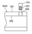
図1は、本考案の第一の実施形態に係るパイプシステムに用いる基本パイプ150Aの縦断面図である。
(First embodiment)
FIG. 1 is a longitudinal sectional view of a
なお、本実施形態に係るパイプシステムは、突起154の取り付け構造のみが図4乃至図8に示した従来のパイプシステムと異なっており、他の構造は図4乃至図8に示した従来のパイプシステムと同一である。
The pipe system according to this embodiment is different from the conventional pipe system shown in FIGS. 4 to 8 only in the mounting structure of the
図1に示すように、基本パイプ150Aには外壁201から内壁202に貫通する貫通孔203が形成されており、貫通孔203の内壁には雌ネジが切られている。
As shown in FIG. 1, the basic pipe 150 </ b> A is formed with a through
さらに、本実施形態に係るパイプシステムにおける突起154には、突起154の軸方向に連続して、雄ネジが切られている雄ネジ部分157が形成されている。雄ネジ部分157の雄ネジは貫通孔203の雌ネジに螺合可能に形成されている。
Further, the
本実施形態に係るパイプシステムによれば、突起154の雄ネジ部分157を基本パイプ150Aに形成されている貫通孔203に螺合させることにより、突起154を基本パイプ150Aの外壁上に固定させることができる。
According to the pipe system of the present embodiment, the
本実施形態に係るパイプシステムによれば、以下の効果を奏する。 The pipe system according to this embodiment has the following effects.
本実施形態に係るパイプシステムによれば、基本パイプ150Aの作製には突起154の溶接工程の実施を必要としない。このため、従来のパイプシステムと比較して、基本パイプ150Aを短時間で、かつ、少ない労力で作製することが可能である。
According to the pipe system according to the present embodiment, it is not necessary to perform the process of welding the
また、突起154を基本パイプ150Aに取り付けた後でも、容易に突起154を基本パイプ150Aから取り外すことが可能である。このため、突起154のサイズまたは形状の変更を必要とする場合であっても、突起154を容易に交換することができる。
Further, even after the
さらに、突起154は、本実施形態に係るパイプシステムの埋設現場において、基本パイプ150Aに取り付けることが可能である。このため、パイプシステムの埋設現場までは、突起154を取り付けることなく、基本パイプ150Aを運搬することが可能であり、突起154が突出していた従来の基本パイプ150Aと比較して、基本パイプ150Aの運搬効率を向上させることが可能である。
Furthermore, the
(第二の実施形態)
図2は、本考案の第二の実施形態に係るパイプシステムに用いる基本パイプ150Aの縦断面図である。
(Second embodiment)
FIG. 2 is a longitudinal sectional view of a
本実施形態に係るパイプシステムにおいては、上述の第一の実施形態に係るパイプシステムと比較して、基本パイプ150Aには、貫通孔203の代わりに、基本パイプ150Aの肉厚を貫通しない凹部204が形成されている。すなわち、凹部204は基本パイプ150Aの外壁201を始点として、基本パイプ150Aの内壁202に到達しない深さを有している。
In the pipe system according to the present embodiment, compared to the pipe system according to the first embodiment described above, the
凹部204の内側側壁には、貫通孔203と同様に、雌ネジが切られている。
Similar to the through
例えば、基本パイプ150Aの肉厚が7.5mmである場合には、凹部204の深さは6乃至7mmに設定される。
For example, when the thickness of the
本実施形態に係るパイプシステムによれば、第一の実施形態に係るパイプシステムによる効果に加えて、基本パイプ150Aのシール性能を低下させないと効果を奏する。
According to the pipe system according to the present embodiment, in addition to the effect of the pipe system according to the first embodiment, there is an effect unless the sealing performance of the
基本パイプ150Aに貫通孔203を形成すると、貫通孔203に突起154を螺合させたとしても、基本パイプ150Aの外側と内側との間の機密性は多少低下するが、貫通孔203に代えて凹部204を形成することにより、そのような機密性の低下を防止することが可能である。
When the through-
上記の実施形態において、突起154の横断面の形状は任意であるが、例えば、突起154の横断面を六角形とすることにより、スパナを用いて、突起154を貫通孔203または凹部204にねじ込むことが可能になる。
In the above-described embodiment, the shape of the cross section of the
また、図3(A)及び図3(B)に示すように、突起154の頂面にプラス(+)またはマイナス(−)型の凹部158を形成することにより、突起154の横断面の形状にかかわらず、プラスまたはマイナスのドライバーを用いて、突起154を回転させることが可能になる。
Further, as shown in FIGS. 3A and 3B, by forming a plus (+) or minus (−)
150A 基本パイプ
150B 第二の基本パイプ
151 拡大径部
152 フランジ
154 突起
157 雄ネジ部分
158 凹部
160 可動フランジ
162 切り欠き
170 パッキン
203 貫通孔
204 凹部
Claims (8)
前記第二の基本パイプの一端には内径が拡大して形成されている拡大径部が形成されているとともに、前記拡大径部に連続して前記拡大径部の外方に広がるフランジが形成されており、
前記基本パイプの一端には、当該一端から離れた位置に少なくとも1個の突起が配置されており、
前記第二の基本パイプと前記基本パイプとは可動フランジを介して相互に接続されており、
前記可動フランジには、前記基本パイプの外周に嵌合し得る内径を有する内側開口が形成されており、
前記内側開口には前記突起が通過し得る大きさの切り欠きが形成されており、
前記可動フランジを介して前記第二の基本パイプと前記基本パイプとを相互に接続する場合には、前記突起と前記切り欠きとが一直線上に位置しないようにして、前記可動フランジを前記第二の基本パイプの前記フランジに接続し、
前記基本パイプの外周には内壁に雌ネジが形成されている貫通孔が形成され、前記突起には前記雌ネジに螺合する雄ネジ部分が形成されており、前記突起は前記雄ネジ部分を前記雌ネジに螺合させることにより前記基本パイプに接続されているパイプシステム。 A pipe system comprising a basic pipe and a second basic pipe connected to the basic pipe,
One end of the second basic pipe is formed with an enlarged diameter part having an enlarged inner diameter, and a flange that extends outward from the enlarged diameter part is formed continuously with the enlarged diameter part. And
One end of the basic pipe has at least one protrusion disposed at a position away from the one end.
The second basic pipe and the basic pipe are connected to each other via a movable flange,
The movable flange is formed with an inner opening having an inner diameter that can be fitted to the outer periphery of the basic pipe,
The inner opening is formed with a notch having a size through which the protrusion can pass,
When the second basic pipe and the basic pipe are connected to each other via the movable flange, the movable flange is connected to the second flange so that the protrusion and the notch are not positioned on a straight line. Connected to the flange of the basic pipe of
A through hole in which an internal thread is formed on the inner wall is formed on the outer periphery of the basic pipe, and an external thread portion that is screwed into the internal thread is formed in the protrusion, and the protrusion has the external thread portion. A pipe system connected to the basic pipe by being screwed into the female screw.
前記第二の基本パイプの一端には内径が拡大して形成されている拡大径部が形成されているとともに、前記拡大径部に連続して前記拡大径部の外方に広がるフランジが形成されており、
前記基本パイプの一端には、当該一端から離れた位置に少なくとも1個の突起が配置されており、
前記第二の基本パイプと前記基本パイプとは可動フランジを介して相互に接続されており、
前記可動フランジには、前記基本パイプの外周に嵌合し得る内径を有する内側開口が形成されており、
前記内側開口には前記突起が通過し得る大きさの切り欠きが形成されており、
前記可動フランジを介して前記第二の基本パイプと前記基本パイプとを相互に接続する場合には、前記突起と前記切り欠きとが一直線上に位置しないようにして、前記可動フランジを前記第二の基本パイプの前記フランジに接続するパイプシステムにおける前記基本パイプであって、
前記基本パイプの外周には内壁に雌ネジが形成されている貫通孔が形成され、前記突起には前記雌ネジに螺合する雄ネジ部分が形成されており、前記突起は前記雄ネジ部分を前記雌ネジに螺合させることにより前記基本パイプに接続されていることを特徴とする基本パイプ。 A pipe system comprising a basic pipe and a second basic pipe connected to the basic pipe,
One end of the second basic pipe is formed with an enlarged diameter part having an enlarged inner diameter, and a flange that extends outward from the enlarged diameter part is formed continuously with the enlarged diameter part. And
One end of the basic pipe has at least one protrusion disposed at a position away from the one end.
The second basic pipe and the basic pipe are connected to each other via a movable flange,
The movable flange is formed with an inner opening having an inner diameter that can be fitted to the outer periphery of the basic pipe,
The inner opening is formed with a notch having a size through which the protrusion can pass,
When the second basic pipe and the basic pipe are connected to each other via the movable flange, the movable flange is connected to the second flange so that the protrusion and the notch are not positioned on a straight line. The basic pipe in a pipe system connected to the flange of the basic pipe of
A through hole in which an internal thread is formed on the inner wall is formed on the outer periphery of the basic pipe, and an external thread portion that is screwed into the internal thread is formed in the protrusion, and the protrusion has the external thread portion. A basic pipe which is connected to the basic pipe by being screwed into the female screw.
Priority Applications (1)
| Application Number | Priority Date | Filing Date | Title |
|---|---|---|---|
| JP2008000226U JP3140550U (en) | 2008-01-18 | 2008-01-18 | Pipe system |
Applications Claiming Priority (1)
| Application Number | Priority Date | Filing Date | Title |
|---|---|---|---|
| JP2008000226U JP3140550U (en) | 2008-01-18 | 2008-01-18 | Pipe system |
Publications (1)
| Publication Number | Publication Date |
|---|---|
| JP3140550U true JP3140550U (en) | 2008-03-27 |
Family
ID=43290665
Family Applications (1)
| Application Number | Title | Priority Date | Filing Date |
|---|---|---|---|
| JP2008000226U Expired - Fee Related JP3140550U (en) | 2008-01-18 | 2008-01-18 | Pipe system |
Country Status (1)
| Country | Link |
|---|---|
| JP (1) | JP3140550U (en) |
-
2008
- 2008-01-18 JP JP2008000226U patent/JP3140550U/en not_active Expired - Fee Related
Similar Documents
| Publication | Publication Date | Title |
|---|---|---|
| JP6142427B2 (en) | Flange joint reinforcement jig | |
| US9523450B2 (en) | Flange joint connection structure | |
| CN106415104B (en) | Flange joint reinforcement jig | |
| BR112018011101B1 (en) | COMBINATION OF PIPE ELEMENT AND PLUG, AND, PLUG | |
| JP2016023659A (en) | Reinforcement jig of joint part | |
| US20160258560A1 (en) | Joint for high-pressure pipes and joint structure | |
| JP3140550U (en) | Pipe system | |
| JP2009014011A (en) | Expansion joint | |
| JP5917198B2 (en) | Telescopic flexible joint and water faucet with saddle using the same | |
| JP2011231561A (en) | Upper and lower steel pipes jointing structure for steel pipe column and jointing method thereof | |
| KR20110093167A (en) | Ship | |
| JP2020101289A (en) | Reinforcement jig attachment method | |
| JP2024009299A (en) | Pipe fitting separation prevention structure | |
| JP7123325B2 (en) | Joint reinforcement structure | |
| JP6910612B2 (en) | Joint reinforcement structure | |
| JP4578029B2 (en) | Pile head structure and pile head bracket | |
| JP5895413B2 (en) | Steel pipe joint structure | |
| JPH0139984Y2 (en) | ||
| JP2003083484A (en) | Coupling for connecting piping | |
| JPS5853505Y2 (en) | Pipe joint separation prevention fitting | |
| KR20180047622A (en) | an assembly system for a flexible joint | |
| JP2005147164A (en) | Water supply pipe joint and sprinkler head | |
| JPS6235923Y2 (en) | ||
| JP2564340Y2 (en) | Pipe fittings | |
| JP2004225261A (en) | Reinforcement end anchoring device |
Legal Events
| Date | Code | Title | Description |
|---|---|---|---|
| R150 | Certificate of patent or registration of utility model |
Free format text: JAPANESE INTERMEDIATE CODE: R150 |
|
| FPAY | Renewal fee payment (event date is renewal date of database) |
Free format text: PAYMENT UNTIL: 20110305 Year of fee payment: 3 |
|
| LAPS | Cancellation because of no payment of annual fees |