JP3140818U - Underlay board structure - Google Patents
Underlay board structure Download PDFInfo
- Publication number
- JP3140818U JP3140818U JP2008000425U JP2008000425U JP3140818U JP 3140818 U JP3140818 U JP 3140818U JP 2008000425 U JP2008000425 U JP 2008000425U JP 2008000425 U JP2008000425 U JP 2008000425U JP 3140818 U JP3140818 U JP 3140818U
- Authority
- JP
- Japan
- Prior art keywords
- board body
- underlay
- underlay board
- connecting frame
- support member
- Prior art date
- Legal status (The legal status is an assumption and is not a legal conclusion. Google has not performed a legal analysis and makes no representation as to the accuracy of the status listed.)
- Expired - Fee Related
Links
Images




Landscapes
- Tables And Desks Characterized By Structural Shape (AREA)
Abstract
【課題】下敷きボード構造において、下敷きボード本体の傾斜角度の調整、傾斜した状態と水平状態との切り換えを簡便に行いうるようにする。
【解決手段】一つの板面11と一つの底面12とを有する一つの下敷きボード本体10と、位置決め端21及び揺動端22を含み、位置決め端は下敷きボード本体に締結してあり、揺動端は所定の長さを有する、連結用架体20と、連結用架体の揺動端に締結されており、揺動端と共に移動することが可能であり、下敷きボード本体の底面の下もしくは下敷きボード本体のサイドの位置に移動させられる支持部材30を含む。支持部材を下敷きボード本体の底面の下で連結用架体と共に移動させることによって、下敷きボード本体の傾斜角度の調整がなされ、支持部材を下敷きボード本体のサイドの位置に移動させると、下敷きボード本体は水平状態となる。
【選択図】図1In an underlay board structure, adjustment of an inclination angle of an underlay board body and switching between an inclined state and a horizontal state can be easily performed.
An underlay board main body having one plate surface and a bottom surface, a positioning end and a swing end are arranged, and the positioning end is fastened to the underlay board main body. The end has a predetermined length and is fastened to the connecting frame 20 and the rocking end of the connecting frame, and can move together with the rocking end. A support member 30 that is moved to a position on the side of the underlay board body is included. The inclination angle of the underlay board body is adjusted by moving the support member with the connecting frame under the bottom surface of the underlay board body, and when the support member is moved to the side position of the underlay board body, the underlay board body Becomes horizontal.
[Selection] Figure 1
Description
本考案は下敷きボード構造に係り、特に、傾斜角度を調整できる下敷きボード構造に関するものである。 The present invention relates to an underlay board structure, and more particularly to an underlay board structure capable of adjusting an inclination angle.
従来の机面は物を安定した状態で置けるように、水平設計になっていることが多いが、実際、人間が机上で読み書きをするとき、机面は人に対して適切な傾斜角度(約17°)となっているのが最も理想的であり、そうすることで腰部を真っ直ぐに保ち、脊椎の健康を維持することができる。 Conventional desk surfaces are often designed horizontally so that objects can be placed in a stable state, but in fact, when a person reads and writes on a desk, the desk surface is tilted to an appropriate angle (approximately 17 °) is the most ideal, so that the waist can be kept straight and spine health can be maintained.
前記の目的を達成すべく、一部の業者は机面の傾斜角度を調整できる机を開発した。この机の構造は天板に傾斜調整機能をもたせるために、可動式の関節部に位置決め切り替えパーツや強化支持フレームなどの部材を使用する構成である。 In order to achieve the above object, some contractors have developed desks that can adjust the inclination angle of the desk surface. This desk has a structure in which a member such as a positioning switching part or a reinforced support frame is used for a movable joint portion in order to give the top panel a tilt adjusting function.
しかし、可動式の関節部に位置決め切り替えパーツや強化支持フレームなどの部材を必要とするため、材料、組立てコストを低く抑えることができず、その分だけ机の価格が高くなり、消費者に負担がかかってしまうことになる。また、使用する観点からみると、公知の傾斜調整机はその調整機構を天板の下方に設置することが多いため、操作が不便だという欠点が存在する。 However, because the movable joints require parts such as positioning switching parts and reinforced support frames, the material and assembly costs cannot be kept low, and the price of the desk increases accordingly, which burdens consumers. Will be applied. Further, from the viewpoint of use, a known tilt adjusting table often has its adjusting mechanism installed below the top plate, and thus has a drawback that the operation is inconvenient.
そして、他に考えられる問題点としては、既に傾斜調整機能を有さない一般的な机を購入された使用者にとって、その需要を満たすことはできない。 As another possible problem, a user who has already purchased a general desk that does not have a tilt adjustment function cannot satisfy the demand.
よって、従来の構造における問題点を改善し、より理想的で実用性を伴った卓具配件の新型構造を開発することは消費者が待望することであり、関連業者の目指すところでもある。 Therefore, improving the problems in the conventional structure and developing a new structure of tableware arrangement with more ideality and practicality is a long-awaited consumer, and it is also the aim of related companies.
考案者は長年関連製品の設計開発に携わってきた経験を活かし、上述の目標を達成すべく、工夫を凝らした設計を取り入れ、慎重に評価を重ねた後にやっとこのような実用性をもった考案を提案した。 The inventor took advantage of his many years of experience in the design and development of related products, took ingenious designs to achieve the above goals, and finally had such practicality after careful evaluation. Proposed.
本考案は、上記課題を解決した下敷きボード構造を提供することを目的とする。 An object of the present invention is to provide an underlay board structure that solves the above problems.
本考案は、所定の長さ、幅及び板厚を有しており、一つの板面と一つの底面とを有する一つの下敷きボード本体と、
位置決め端及び揺動端を含み、位置決め端は下敷きボード本体に締結してあり、揺動端は所定の長さを有する、連結用架体と、
連結用架体の揺動端に締結されており、揺動端と共に移動することが可能であり、下敷きボード本体の底面の下、もしくは下敷きボード本体のサイドの位置に移動させられる支持部材を含むことを特徴とする。
The present invention has a predetermined length, width and plate thickness, one underlay board body having one plate surface and one bottom surface,
A connecting frame including a positioning end and a swing end, the positioning end being fastened to the underlay board body, and the swing end having a predetermined length;
It includes a support member that is fastened to the rocking end of the connecting frame, can move together with the rocking end, and can be moved to the position below the bottom surface of the underlay board body or the side of the underlay board body. It is characterized by that.
このような調整可能な下敷きボード構造を既設の机面に設置することで、その用途に応じて、傾斜角度を調整することができる。 By installing such an adjustable underlay board structure on an existing desk surface, the inclination angle can be adjusted according to the application.
本考案の第二の目的は下敷きボード本体の連結用架体の位置決め端と長形リード溝の締結部を可動式位置決めピンで固定することで、締付け/緩めるという簡易操作でその支持部材と下敷きボード本体の相対位置及び下敷きボード本体の傾斜角度を調整することができる。 The second object of the present invention is to fix the support member and the underlay by a simple operation of tightening / loosening by fixing the positioning end of the connecting body of the underlay board body and the fastening portion of the long lead groove with a movable positioning pin. The relative position of the board body and the inclination angle of the underlying board body can be adjusted.
本考案の第三の目的はその下敷きボード本体の片側に可動式補助マットを設置したことで、その補助マットを下敷きボード本体の板面の上もしくは下敷きボード本体サイド位置に移動させ、手部を支えたり、ストッパーとしての役割を果たすことができる。 The third purpose of the present invention is to install a movable auxiliary mat on one side of the underlay board main body, so that the auxiliary mat is moved to the position of the underlay board main body or the side of the underlay board main body, and the hand portion is moved. Can support or play a role as a stopper.
以下、本考案の実施例になる下敷きボード構造について説明する。図1〜図8は本考案の調整可能な下敷きボード構造の推奨実施例である。但し、これらの実施例は説明をするための参考であり、実用新案登録の申請に際してはその構造の制限を受けない。 Hereinafter, an underlay board structure according to an embodiment of the present invention will be described. 1 to 8 are preferred embodiments of the adjustable underlay board structure of the present invention. However, these examples are only for reference and are not subject to structural limitations when applying for utility model registration.
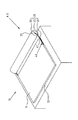
図1は本考案の実施例1になる下敷きボード構造を示す斜視図である。
FIG. 1 is a perspective view showing an underlay board structure according to
下敷きボード構造Aは、角度が調整可能である構成であり、一つの下敷きボード本体10と、連結用架体20と、一つの支持部材30とを有する。
The underlay board structure A has a configuration in which the angle can be adjusted, and includes one
下敷きボード本体10は、所定の長さ、幅及び板厚を有しており、一つの板面11と一つの底面12を有する。
The
連結用架体20は、位置決め端21及び揺動端22を含み、位置決め端21は下敷きボードの本体10に締結してあり、揺動端22は所定の長さを有する。
The connecting
支持部材30は、連結用架体20の揺動端22に締結されており、揺動端22と共に移動することが可能であり、支持部材30を下敷きボード本体10の底面12の下、もしくは下敷きボード本体10のサイドの位置に移動させることができる。この構造において、支持部材30は、一つのドラム31よりなる。
The
次に、上記下敷きボード構造Aの使用状況について説明する。 Next, the use situation of the underlay board structure A will be described.
図1に示すように、調整可能な下敷きボード構造Aは、一つの下敷きボード本体10の片側(使用者から遠い側)の両サイドに連結用架体20が装着してある。連結用架体20の位置決め端21と下敷きボード本体10の締結部は、一つの固定用パーツ44によって固定してある。連結用架体20の別の揺動端22に装着されている支持部材30は定置部でスクロール調整を行うことができる。
As shown in FIG. 1, in the adjustable underlay board structure A, a connecting
なお、連結用架体20は一つの曲折部23を有しており、これによって、スクロール支持部材30を固定し、滑りや位置ずれを防ぐことが可能である。
Note that the connecting
図2は本考案の実施例2になる下敷きボード構造A1を示す斜視図、図4は下敷きボード構造A1の側面図である。 2 is a perspective view showing an underlay board structure A1 according to a second embodiment of the present invention, and FIG. 4 is a side view of the underlay board structure A1.
下敷きボード構造A1は、下敷きボード本体10には、連結用架体20の位置決め端21を締結する部位に長形リード溝40が形成してあり、連結用架体20の位置決め端21が可動式位置決めピン41で長形リード溝40に締結してある構成である。
In the underlay board structure A1, a
可動式位置決めピン41の長形リード溝40への締結が緩め状態にある場合には、図5に示すように、可動式位置決めピン41を長形リード溝40の限られた距離の範囲内でスライドさせて連結用架体20を動かして、支持部材30と下敷きボード本体10の相対位置及び下敷きボード本体10の傾斜角度を調整することができる。また、今までの使用経験及び研究により、下敷きボードの傾斜角度を約10〜17°とした場合が最も人体力学に適合しており、使用者の背筋をまっすぐに伸ばし、脊椎に良い姿勢を保つことができる。
When the fastening of the
なお、連結用架体20は一つの曲折部23を有しており、これによって、スクロール支持部材30を固定し、滑りや位置ずれを防ぐことが可能である。
Note that the connecting
図3は、支持部材30を移動させて下敷きボード本体10のサイドに位置させて、下敷きボード本体10を、傾斜した状態から水平状態に切り換えた状態を示す。
FIG. 3 shows a state where the
図5に示すように、支持部材30の位置を移動させることによって、下敷きボード構造Aは下敷きボード本体10の傾斜角度が調整できる。また、図6に示すように、支持部材30を利用して下敷きボード本体10の使用者からの距離を調整することもできる。使用者が着座時に垂直姿勢から後方にもたれたとき、下敷きボード本体10を後方の所定位置に引っ張るだけで距離を調整することができ、下敷きボード本体10の傾斜角度をいちいち調整する手間が省ける。
As shown in FIG. 5, by moving the position of the
図7は本考案の実施例3になる下敷きボード構造A2を示す。 FIG. 7 shows an underlay board structure A2 according to Embodiment 3 of the present invention.
下敷きボード本体10のうち、使用者より遠い側は、上記実施例2と同様に、支持部材30の連結用架体20が可動式位置決めピン41によって長形リード溝40に取り付けてある構成であり、使用者に近い側には、一つの補助マット50が可動フレーム51によって下敷きボード本体10に連結されている。
In the underlay board
補助マット50は、図8に示すように、可動フレーム51を回動させつつ、下敷きボード本体10の板面11の上、或いは、下敷きボード本体10のサイド位置に移動させることができる。使用者は補助マット50に手を載せたり、もしくは補助マット50をストッパーとして利用することができる。
As shown in FIG. 8, the
図9は本考案の実施例4になる下敷きボード構造A3を示す。 FIG. 9 shows an underlay board structure A3 according to Embodiment 4 of the present invention.
下敷きボード本体10Bの板面11上に一つの軟質マット14が設置してある。これによって、使用者は板面11の上で書写することができる。
One
支持部材30Bは、一つのスライド支持座31Bよりなる。スライド支持座31Bの底部にローラ32が装着してあり、スライド支持座31Bはスライド動作をすることができる。
The
また、図12に示すように、スライド支持座31Bには一つの収容部42が設置してあり、この中に、鉛筆、消しゴム、定規などの文房具もしくはその他の小物、ワークを収納することができる。
As shown in FIG. 12, the
下敷きボード本体10Bのうち、長形リード溝40に近接した部分の両側には、外側に延びたウィング部13R,13Lが設けられている。下敷きボード本体10の傾斜高さを調整するときには、使用者は両手でそのウィング部13R,13Lを持ったまま連結用架体20を指で動かし、連結用架体20を長形リード溝40の中でスライドさせ、調整することができる。
図13に示すように、可動式位置決めピン41は一つのボルト付きロックピンである。可動式位置決めピン41と長形リード溝40の間に連結用架体20を設置し、連結用架体20に可動式位置決めピン41を締結するための一つの通孔201を設置し、長形リード溝40の中に一つの滑りナット座42が設置してある。可動式位置決めピン41は、滑りナット座42を貫通して、長形リード溝40の中で固定してある。使用者は可動式位置決めピン41を少し緩め、可動式位置決めピン41と滑りナット座42とを長形リード溝40の中でスライドさせて必要な位置に調整した後、可動式位置決めピン40を締め付けることによって、高さ調整の目的を達成することができる。
As shown in FIG. 13, the
図11は、連結用架体20を回動させると共に長形リード溝40に沿って移動させて、下敷きボード本体10Bの下側の支持部材30Bを、下敷きボード本体10Bの使用者側より遠い側の縁より外側のサイドの位置に移動させて、下敷きボード本体10Bを傾斜状態から水平状態に切り換えるときの状態を示す。図10は下敷きボード本体10Bの移動が完了して、下敷きボード本体10Bが切り換わって水平状態となった状態を示す。
In FIG. 11, the connecting
図14は本考案のもう一つの実施例になる可動式位置決めピン41Bを使用した連結用架体の長形リード溝への設置構造を示す。
FIG. 14 shows an installation structure of a connecting frame in a long lead groove using a
この可動式位置決めピン41Bは、一つの凹溝410を有する。連結用架体20の片側に設置された一つの突出棒202をその凹溝410に挿入してある。可動式位置決めピン41Bを調整したときに、連結用架体20に前記に掲げた可動式位置決めピン40と滑りナット座42の長形リード溝40内を限られた距離の範囲内でスライド動作を行わせることが出来る。
The
図15は、支持部材30Cと連結用架体20との接続の構造を示す。支持部材30Cには、一つの位置制御溝52が形成してある。図16に示すように、連結用架体20は位置制御溝52を通って支持部材30Cの中に組み入れられる。これによって、連結用架体20に支持される支持部材30Cを任意の材質のものに変更することができる。
FIG. 15 shows a connection structure between the
調整可能な下敷きボード構造を太ももの上において使用する場合には、軟性材質で形成された支持部材30Cに変更することによって、硬い材質による両足の血管神経への圧迫や痛みを防止することができる。
When the adjustable underlay board structure is used on the thigh, it is possible to prevent pressure and pain on the vascular nerves of both feet due to the hard material by changing to the
本考案は以下の効果を有する。
(1)調整可能な下敷きボード構造Aは既設の机に設置できることに加えて、傾斜角度を調整できるという機能を備えており、更に、支持部材30の位置を変えるだけで下敷きボード本体10を水平もしくは傾斜した状態に切り換えることができる。よって、下敷きボード構造Aは、使用者の要求に見合った、使い勝手の良い、実用性及び進歩性を兼ね備えている。
(2)連結用架体20の位置決め端21と長形リード溝40の締結部を可動式位置決めピン41で固定してあるので、可動式位置決めピン41と長形リード溝40の間は締付け/緩めるという簡易操作によって、可動式位置決めピン41と連結用架体20を同時に動かし、長形リード溝40内を定まった距離の範囲内でスライド動作を行わせ、その支持部材30と下敷きボード本体10の相対位置及び下敷きボード本体10の傾斜角度を調整することができる。
(3)下敷きボード本体10のうち支持部材30が設けてある側とは反対側に、可動式補助マット50が設置してあり、この補助マット50を下敷きボード本体10の板面11の上の位置或いは横の位置に移動させると、手を支えたり、ストッパーとしての役割を果たすことができる。
The present invention has the following effects.
(1) In addition to being able to be installed on an existing desk, the adjustable underlay board structure A has a function of adjusting the inclination angle, and further, the underlay board
(2) Since the fastening portion of the positioning
(3) A movable
また、本考案は、支持部材30を利用して下敷きボード本体10の机上における距離を調整することができるという、新しい機能を有する。これによって、使用者が着座時に垂直姿勢から後方にもたれた時、下敷きボード本体10を後方の所定位置まで引っ張るだけで距離を調整することができ、下敷きボード本体10の傾斜角度を調整する必要がなく、便利で快適な操作性を実現できる。
In addition, the present invention has a new function that the distance of the
上述の実施例は本考案を具体的に説明したものであり、文中では特定の専門用語を用いて説明しているが、実用新案登録請求の範囲を限定するものではなく、この技術分野を熟知した当事者は本考案の精神及び原則を逸脱しない限り、本考案に変更または改良を加えることができる。しかし、それらの変更または改良は全て本願の実用新案登録請求の範囲に含まれるものである。 The above-described embodiments are specific descriptions of the present invention, and are described using specific technical terms in the text. However, they do not limit the scope of claims for registration of utility models, and are familiar with this technical field. Those skilled in the art can make changes or improvements to the present invention without departing from the spirit and principle of the present invention. However, all such changes or improvements are included in the scope of the utility model registration claims of the present application.
A、A1,A2、A3 下敷きボード構造
10、10B下敷きボード本体
11 板面
12 底面
13R,13L ウィング部
14 軟質マット
20 連結用架体
201 通孔
202 突出棒
21 位置決め端
22 揺動端
23 曲折部
30、30B、30C 支持部材
31 ドラム
31B スライド支持座
40 長形リード溝
41,41B 可動式位置決めピン
410 凹溝
42 収容部
43 滑りナット座
44 固定用パーツ
50 補助マット
51 可動フレーム
52 位置制御溝
A, A1, A2, A3
Claims (6)
位置決め端(21)及び揺動端(22)を含み、前記位置決め端(21)は前記下敷きボード本体(10)に締結してあり、前記揺動端(22)は所定の長さを有する、連結用架体(20)と、
前記連結用架体(20)の前記揺動端(22)に締結されており、前記揺動端(22)と共に移動することが可能であり、前記下敷きボード本体(10)の底面(12)の下、もしくは前記下敷きボード本体(10)のサイドの位置に移動させられる支持部材(30)を含む下敷きボード構造。 One underlay board body (10) having a predetermined length, width and plate thickness and having one plate surface (11) and one bottom surface (12);
A positioning end (21) and a swing end (22), wherein the positioning end (21) is fastened to the underlying board body (10), and the swing end (22) has a predetermined length; A connecting frame (20);
It is fastened to the rocking end (22) of the connecting frame (20) and can move together with the rocking end (22). The bottom surface (12) of the underlay board body (10) Or a support board structure including a support member (30) that is moved to a position on the side of the base board body (10).
前記ドラム(31)には、前記連結用架体(20)から取り外し及び交換のための一つの位置制御溝(52)が形成してある、請求項1に記載の下敷きボード構造。 The support member comprises one drum (31),
The underlay board structure according to claim 1, wherein the drum (31) is formed with a single position control groove (52) for removal and replacement from the connecting frame (20).
前記スライド支持座には、ワークを収容できる一つの収容部(42)が設けてある、請求項1に記載の下敷きボード構造。 The support member comprises one slide support seat (31B),
The underlay board structure according to claim 1, wherein the slide support seat is provided with a single storage portion (42) capable of storing a workpiece.
前記連結用架体(20)の位置決め端(21)が、可動式位置決めピン(41)で上記長形リード溝(40)に締結してあり、
前記可動式位置決めピン(41)の長形リード溝(40)への締結が緩め状態にある場合には、前記可動式位置決めピン(41)を長形リード溝(40)の限られた距離の範囲内でスライドさせて前記連結用架体(20)を動かして、前記支持部材(30)と前記下敷きボード本体(10)の相対位置及び下敷きボード本体(10)の傾斜角度が調整される、請求項1に記載の下敷きボード構造。 A long lead groove (40) is formed in a portion for fastening the positioning end (21) of the connecting frame (20) of the underlay board body (10),
The positioning end (21) of the connecting frame (20) is fastened to the long lead groove (40) by a movable positioning pin (41).
When the fastening of the movable positioning pin (41) to the long lead groove (40) is in a loosened state, the movable positioning pin (41) is moved to a limited distance of the long lead groove (40). By sliding within the range and moving the connecting frame (20), the relative position of the support member (30) and the underlying board body (10) and the inclination angle of the underlying board body (10) are adjusted. The underlay board structure according to claim 1.
前記補助マット(50)は、可動フレーム(51)を介して下敷きボード本体(10)に取り付けられており、下敷きボード本体の板面(11)の上、もしくは下敷きボード本体(10)のサイド位置に移動させられる、請求項1に記載の下敷きボード構造。 One auxiliary mat 50 is installed on the side of the underlay board body (10) close to the user,
The auxiliary mat (50) is attached to the underlying board body (10) via a movable frame (51), and is located on the plate surface (11) of the underlying board body or the side position of the underlying board body (10). The underlay board structure according to claim 1, wherein the underlay board structure is moved.
The underlay board structure according to claim 4, wherein the underlay board body (10) has a wing portion (13R, 13L) extending outward at a location close to the elongated lead groove (40).
Priority Applications (1)
| Application Number | Priority Date | Filing Date | Title |
|---|---|---|---|
| JP2008000425U JP3140818U (en) | 2008-01-30 | 2008-01-30 | Underlay board structure |
Applications Claiming Priority (1)
| Application Number | Priority Date | Filing Date | Title |
|---|---|---|---|
| JP2008000425U JP3140818U (en) | 2008-01-30 | 2008-01-30 | Underlay board structure |
Publications (1)
| Publication Number | Publication Date |
|---|---|
| JP3140818U true JP3140818U (en) | 2008-04-10 |
Family
ID=43290917
Family Applications (1)
| Application Number | Title | Priority Date | Filing Date |
|---|---|---|---|
| JP2008000425U Expired - Fee Related JP3140818U (en) | 2008-01-30 | 2008-01-30 | Underlay board structure |
Country Status (1)
| Country | Link |
|---|---|
| JP (1) | JP3140818U (en) |
-
2008
- 2008-01-30 JP JP2008000425U patent/JP3140818U/en not_active Expired - Fee Related
Similar Documents
| Publication | Publication Date | Title |
|---|---|---|
| TW388808B (en) | Improved keyboard support mechanism | |
| CN1306893C (en) | Back of Chair | |
| US20110127820A1 (en) | Adjustment device for chairs | |
| JPH06253942A (en) | Chair | |
| KR101263464B1 (en) | Buffer cushion for Desk sticking type Posture correction | |
| US7510215B2 (en) | Book grip | |
| US20120074284A1 (en) | Flexible Support Structure | |
| JP4176462B2 (en) | Chair headrest device | |
| JP3140818U (en) | Underlay board structure | |
| KR200437259Y1 (en) | Reading desk | |
| KR200413830Y1 (en) | Desk with adjustable reading desk. | |
| US7938069B2 (en) | Adjustable backing plate structure | |
| KR101952082B1 (en) | Sliding folding chairs with seat plate with front seat height adjustment | |
| JP3157652U (en) | Multifunctional folding table | |
| KR200275780Y1 (en) | Computer working chair | |
| CN201064280Y (en) | Adjustable backing plate structure | |
| JP5890660B2 (en) | Chair | |
| KR200245491Y1 (en) | A writing and reading stand | |
| CN223649040U (en) | A highly flexible all-in-one computer rotating stand | |
| KR200427929Y1 (en) | Swivel health reading rack | |
| JP2006102101A (en) | Table | |
| KR100734947B1 (en) | Portable reading desk | |
| JP4384927B2 (en) | Chair | |
| CN215411242U (en) | A detachable desktop stand | |
| KR101326564B1 (en) | an attachable and detachable shelf for chairs and the chair using thereof |
Legal Events
| Date | Code | Title | Description |
|---|---|---|---|
| R150 | Certificate of patent or registration of utility model |
Free format text: JAPANESE INTERMEDIATE CODE: R150 |
|
| FPAY | Renewal fee payment (event date is renewal date of database) |
Free format text: PAYMENT UNTIL: 20110319 Year of fee payment: 3 |
|
| FPAY | Renewal fee payment (event date is renewal date of database) |
Free format text: PAYMENT UNTIL: 20110319 Year of fee payment: 3 |
|
| FPAY | Renewal fee payment (event date is renewal date of database) |
Free format text: PAYMENT UNTIL: 20120319 Year of fee payment: 4 |
|
| S111 | Request for change of ownership or part of ownership |
Free format text: JAPANESE INTERMEDIATE CODE: R323113 |
|
| FPAY | Renewal fee payment (event date is renewal date of database) |
Free format text: PAYMENT UNTIL: 20120319 Year of fee payment: 4 |
|
| R350 | Written notification of registration of transfer |
Free format text: JAPANESE INTERMEDIATE CODE: R350 |
|
| FPAY | Renewal fee payment (event date is renewal date of database) |
Free format text: PAYMENT UNTIL: 20130319 Year of fee payment: 5 |
|
| FPAY | Renewal fee payment (event date is renewal date of database) |
Free format text: PAYMENT UNTIL: 20130319 Year of fee payment: 5 |
|
| FPAY | Renewal fee payment (event date is renewal date of database) |
Free format text: PAYMENT UNTIL: 20140319 Year of fee payment: 6 |
|
| LAPS | Cancellation because of no payment of annual fees |